EP2361700B1 - Strangpresse zum Herstellen von Profilen aus Nichteisenmetall - Google Patents
Strangpresse zum Herstellen von Profilen aus Nichteisenmetall Download PDFInfo
- Publication number
- EP2361700B1 EP2361700B1 EP11000975A EP11000975A EP2361700B1 EP 2361700 B1 EP2361700 B1 EP 2361700B1 EP 11000975 A EP11000975 A EP 11000975A EP 11000975 A EP11000975 A EP 11000975A EP 2361700 B1 EP2361700 B1 EP 2361700B1
- Authority
- EP
- European Patent Office
- Prior art keywords
- extrusion press
- press according
- electric motor
- phase
- pump
- Prior art date
- Legal status (The legal status is an assumption and is not a legal conclusion. Google has not performed a legal analysis and makes no representation as to the accuracy of the status listed.)
- Active
Links
- 239000002184 metal Substances 0.000 title claims description 6
- 229910052751 metal Inorganic materials 0.000 title claims description 6
- 238000004519 manufacturing process Methods 0.000 title claims description 4
- 238000001125 extrusion Methods 0.000 title claims 11
- -1 ferrous metals Chemical class 0.000 title 1
- 239000012530 fluid Substances 0.000 claims description 17
- 230000002457 bidirectional effect Effects 0.000 claims description 11
- 238000000034 method Methods 0.000 description 5
- 238000003825 pressing Methods 0.000 description 5
- CWYNVVGOOAEACU-UHFFFAOYSA-N Fe2+ Chemical compound [Fe+2] CWYNVVGOOAEACU-UHFFFAOYSA-N 0.000 description 4
- 239000007858 starting material Substances 0.000 description 2
- 230000001133 acceleration Effects 0.000 description 1
- 125000004122 cyclic group Chemical group 0.000 description 1
- 238000010586 diagram Methods 0.000 description 1
- 238000005265 energy consumption Methods 0.000 description 1
- 238000009420 retrofitting Methods 0.000 description 1
- 238000000926 separation method Methods 0.000 description 1
- 239000007787 solid Substances 0.000 description 1
- 239000002918 waste heat Substances 0.000 description 1
Images

Classifications
-
- B—PERFORMING OPERATIONS; TRANSPORTING
- B21—MECHANICAL METAL-WORKING WITHOUT ESSENTIALLY REMOVING MATERIAL; PUNCHING METAL
- B21C—MANUFACTURE OF METAL SHEETS, WIRE, RODS, TUBES OR PROFILES, OTHERWISE THAN BY ROLLING; AUXILIARY OPERATIONS USED IN CONNECTION WITH METAL-WORKING WITHOUT ESSENTIALLY REMOVING MATERIAL
- B21C23/00—Extruding metal; Impact extrusion
- B21C23/21—Presses specially adapted for extruding metal
- B21C23/211—Press driving devices
-
- B—PERFORMING OPERATIONS; TRANSPORTING
- B21—MECHANICAL METAL-WORKING WITHOUT ESSENTIALLY REMOVING MATERIAL; PUNCHING METAL
- B21C—MANUFACTURE OF METAL SHEETS, WIRE, RODS, TUBES OR PROFILES, OTHERWISE THAN BY ROLLING; AUXILIARY OPERATIONS USED IN CONNECTION WITH METAL-WORKING WITHOUT ESSENTIALLY REMOVING MATERIAL
- B21C31/00—Control devices, e.g. for regulating the pressing speed or temperature of metal; Measuring devices, e.g. for temperature of metal, combined with or specially adapted for use in connection with extrusion presses
Definitions
- the invention relates to an extruder for producing profiles of non-ferrous metal, wherein the extruder has at least one ram, which is driven by at least one hydraulic piston-cylinder system, wherein the at least one hydraulic piston-cylinder system supplied by at least one pump with hydraulic fluid and wherein the at least one pump is driven by an electric motor, which is in communication with a three-phase power supply and is provided with Mittein for soft start.
- a generic extruder is from the EP 2 000 226 B1 known.
- a three-phase asynchronous motor is used to drive the pump.
- star-delta circuit For gently starting such high-performance motors, in particular three-phase motors, it is known that these are formed with a star-delta circuit.
- the star-Dreteck circuit is used to limit the starting current of an asynchronous motor in delta connection. The motor is brought to speed in the star connection. When switching is then theoretically only the delta current needed, which corresponds to the current speed. Thus, the inrush current is reduced to 1/3 of the current in the case of delta direct turn-on.
- the mains phases and motor field may be in opposition. This leads to compensation processes, which can disadvantageously lead to a very high switching current peak.
- the invention is therefore the object of a generic extruder in such a way that on the one hand it is possible to achieve a problematic startup of the system, on the other hand in operation but then also to drive an energy-efficient operation and in particular the motors for driving the pump only in the To operate dimensions as required by the pressing process.
- This object is achieved in that the means for soft start to perform a phase angle of the electric motor supplied AC separation are formed.
- At least two thyristors or bidirectional thyristor triodes are provided to cut at least two of the three phases of the AC voltage.
- the electric motor is in particular an asynchronous motor.
- a pump can supply two or more hydraulic piston-cylinder systems with hydraulic fluid. But it is also possible that several pumps supply via communicating fluid lines at least one hydraulic piston-cylinder system with hydraulic fluid. In the latter case it can be provided that supply the number of pumps via the communicating fluid lines at least two hydraulic piston-cylinder systems with hydraulic fluid.
- thyristors or triacs are preferably provided, which make the phase angle of the voltage and control.
- the thyristors or triacs reduce the voltage when switched on by means of a phase control. Subsequently, the phase control can be reduced until the full mains voltage is reached.
- the electronics can be bridged by means of a relay or a contactor to reduce the power loss. As a result, a start under nominal load is possible.
- variable pump shut-off rules out that pumps only produce waste heat.
- the related risk increases without the use of the invention to the extent the greater the number of unneeded pumps during pressing.
- the embodiment of the invention is characterized by a simple technique that is mature available.
- the pumps not required in the pressing process can be switched off in a simple manner. This can be done in particular from pressing times of more than 90 seconds, which - as stated - corresponds to a large part of the production. Even short cycles are energy-efficient mobile.
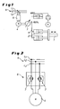
- the Fig. 1 shows a press ram 1 of an extruder for producing profiles of non-ferrous metal, which is actuated by two hydraulic piston-cylinder systems 2 (see the direction of the double arrow in Fig. 1 ).
- the hydraulic piston-cylinder systems 2 receive pressurized hydraulic fluid from a pump 3 via a fluid line 8.
- the pump 3 in turn is driven by an electric motor 4.
- the electric motor 4 is electrically connected to a three-phase network 5, which has the three phases L 1 , L 2 and L 3 . Between the three-phase network 5 and the Electric motor 4, a motor controller (electronic circuit) is arranged, which is referred to as means 6 for soft start.
- a motor controller electronic circuit
- the means 6 for soft start are in Fig. 2 shown in more detail.
- the means 6 comprise for two phases - namely for the phases L1 and L3 - depending on a bidirectional thyristor triode 7.
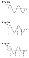
- the operation of the bidirectional thyristor triode 7 is in the FIGS. 3a to 3c played.
- Fig. 3a the uninfluenced sinusoidal curve of the voltage U of a phase over time t is sketched. This voltage curve corresponds to the full network performance and is supplied to the electric motor 4 when the engine is running and should bring full power.
- the phase of the voltage waveform U is cut. Accordingly, the power is transmitted from the mains to the electric motor 4 only when the bidirectional thyristor triode 7 is "ignited".
- the times t, to which this takes place periodically, are indicated by the arrows 9 - symbolizing the ignition - in Fig. 3b and 3c specified. Only the solid areas of the voltage curve thus ensure that the electric motor 4 energy is supplied from the three-phase network 5.
- the dashed curves indicate the time range over which - in the absence of ignition which has not yet occurred - no energy is supplied to the electric motor 4.
- FIGS. 3b and 3c show that depending on the ignition timing more or less energy is passed from the three-phase system to the electric motor. In the situation, how they look Fig. 3b results, it is more energy than in the case of the later ignition according to Fig. 3c ,
- Fig. 4 It can be seen that three electric motors 4 operate in parallel in order to supply two hydraulic piston-cylinder systems 2 connected in parallel with pressurized fluid via a fluid line 8.
- FIG. 3 shows three pumps 3 associated with the piston-cylinder systems 2, each electric motor 4 of each pump 3 being provided with means 6 for soft starting and the two lower pumps being switched off as required.
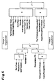
- Fig. 5 is shown - but only very schematically - that between an upper state (“pump X on”) and a lower state (“pump X off”) can also be acted upon by the means 6 for soft start to either start the electric motor or shut down.
- the pumps can be operated as needed. For example, they only start to block change or depending on the press speed that is to be achieved.
- the retrofitting of the proposed system according to the invention is simple, since the electric motor or frequency converter does not have to be FU-suitable. Power cables can be used without screen. Furthermore, there is only a small amount of space in the control cabinet.
Description
- Die Erfindung betrifft eine Strangpresse zum Herstellen von Profilen aus Nichteisenmetall, wobei die Strangpresse mindestens einen Pressstempel aufweist, der durch mindestens ein hydraulisches Kolben-Zylinder-System angetrieben wird, wobei das mindestens eine hydraulische Kolben-Zylinder-System von mindestens einer Pumpe mit Hydraulikfluid versorgt wird und wobei die mindestens eine Pumpe von einem Elektromotor angetrieben wird, der mit einem Drehstromnetz in Verbindung steht und mit Mittein zum Sanftstart versehen ist.
- Eine gattungsgemäße Strangpresse ist aus der
EP 2 000 226 B1 bekannt. Hier wird zum Antrieb der Pumpe ein Dreiphasen-Asynchronmotor eingesetzt. - Zum sanften Anfahren derartiger leistungsstarker Motoren, wie insbesondere Drehstrommotoren, ist es bekannt, dass diese mit einer Stern-Dreieck-Schaltung ausgebildet sind. Die Stern-Dreteck-Schaltung wird eingesetzt, um den Anlaufstrom eines Asynchronmotors in Dreieckschaltung zu begrenzen. Dabei wird der Motor in der Sternschaltung auf Drehzahl gebracht. Beim Umschalten wird dann theoretisch nur noch der Dreieckstrom benötigt, der der aktuellen Drehzahl entspricht. Somit wird der Einschaltstrom auf 1/3 gegenüber dem Strom bei Dreieck-Direkteinschaltung reduziert. Jedoch können beim Umschatten von Stern- auf Dreieck-Schaltung die Netzphasen und das Motorfeld Opposition zueinander stehen. Dies führt zu Ausgleichsvorgängen, was nachteilig zu einer sehr hohen Umschaltstromspitze führen kann.
- Insbesondere ist es beim Einsatz der Stern-Dreieck-Umschaltung und beim Einsatz eines FU-Schalters nicht bzw. nur bedingt möglich, eine zyklische Pumpenschaltung energieeffizient zu fahren.
- Wie bei in die Motorsteuerung Integrierten Fehlerspannungsschutzschaltern (FU-Schaltern) ist ein häufiges Abschalten mit Problemen behaftet oder sogar unmöglich. Abhllfe wird geschaffen, indem die Motoren nicht abgeschaltet werden und die nicht benötigten Pumpen permanent durchlaufen.
- Dies hat ertergetische Nachteile zur Folge, da die Pumpen stärker betrieben werden, als es für die Durchführung der Pressprozesse nötig wäre.
- Der Erfindung liegt daher die Aufgabe zugrunde, eine gattungsgemäße Strangpresse so auszubilden, dass es einerseits möglich wird, einen problemiosen Anlauf des Systems zu erreichen, andererseits im Betrieb dann aber auch eine energieeffiziente Betriebsweise zu fahren und Insbesondere die Motoren zum Antrieb der Pumpe nur in dem Maße zu betreiben, wie es der Pressprozess erfordert.
- Diese Aufgabe wird erfindungsgemäß dadurch gelöst, dass die Mittel zum Sanftstart zur Ausführung eines Phasenanschnitts der dem Elektromotor zugeführten Wechselspennung ausgebildet sind.
- Nach einer bevorzugten Ausführung sind mindestens zwei Thyristoren oder Zweirichtungs-Thyristortrioden vorhanden, um mindestens zwei der drei Phasen der Wechselspannung anzuschneiden. Vorgesehen werden können aber auch drei Thyristoren oder Zweirichtungs-Thyristortrioden, um alle drei Phasen der Wechselspannung anzuschneiden.
- Der Elektromotor ist insbesondere ein Asynchronmotor.
- Eine Pumpe kann zwei oder mehr hydraulische Kolben-Zylinder-Systeme mit Hydraulikfluid versorgen. Möglich ist es aber auch, dass mehrere Pumpen über kommunizierende Fluidleitungen mindestens ein hydraulisches Kolben-Zylinder-System mit Hydraulikfluid versorgen. In letzterem Falle kann vorgesehen werden, dass die Anzahl von Pumpen über die kommunizierenden Fluidleitungen mindestens zwei hydraulische Kolben-Zylinder-Systeme mit Hydraulikfluid versorgen.
- Generell werden mit dem erfindungsgemäß zum Einsatz kommenden Sanftanlauf Maßnahmen zur Leistungsbegrenzung beim Einschalten eines elektrischen Gerätes beschrieben, vorliegend eines elektrischen Motors. Hierbei wird zum einen der Einschaltstrom des Gerätes verringert, d. h. es erfolgt eine Einschaltstrombegrenzung. Es wird damit auch das Ansprechen eines Leitungsschutzschalters oder ein starker Spannungseinbruch der Netzspannung vermieden. Zum anderen werden die vom Elektromotor angetriebenen Komponenten vor zu großen Drehmomenten und Beschleunigungen geschützt.
- Zur Einschaltstrombegrenzung wird bevorzugt der Einsatz von Thyristoren oder Triacs vorgesehen, die den Phasenanschnitt der Spannung vornehmen und steuern. Die Thyristoren bzw. Triacs verringern beim Einschalten mittels eines Phasenanschnitts die Spannung. Anschließend kann der Phasenanschnitt reduziert werden, bis die volle Netzspannung erreicht ist. Beim Erreichen der vollen Spannung kann die Elektronik mittels eines Relais bzw. eines Schützes überbrückt werden, um die Verlustleistung zu verringern. Hierdurch wird auch ein Anlaufen unter Nennlast möglich.
- Der problematische Anlauf des Systems und ein womöglich zu hoher Energieverbrauch lassen sich erfindungsgemäß also dadurch vermeiden, dass die Motorsteuerung mit einem Sanftstarter ausgerüstet wird. So lässt sich in einfacher Weise erreichen, dass nicht benötigte Antriebe zu den Pumpen in kurzen Zyklen abgeschaltet und wieder eingeschaltet werden können. Hierbei ist zu beachten, dass bei einem Großteil der normalen Produktion die Presszeiten über 90 Sekunden liegen. Mit der vorgeschlagenen Lösung ist es ohne hohe Lastspitzen und energieeffizient möglich, beliebige Lastspiele zu fahren, wobei die Pumpen auch versetzt eingeschaltet werden können.
- Somit ergibt sich ein hohes Energie-Einsparpotential für die Zeiten, in denen die Antriebe abgeschaltet worden sind, das mit der Erfindung genutzt werden kann.
- Die variable Pumpenabschaltung schließt aus, dass Pumpen nur Abwärme produzieren. Die diesbezügliche Gefahr steigt ohne Einsatz der Erfindung in dem Maße, je größer die Anzahl nicht benötigter Pumpen beim Pressen ist.
- Die erfindungsgemäße Ausgestaltung zeichnet sich durch eine einfache Technik aus, die ausgereift zur Verfügung steht.
- Die beim Pressvorgang nicht benötigten Pumpen können in einfacher Weise abgeschaltet werden. Dies kann insbesondere ab Presszeiten von mehr als 90 Sekunden erfolgen, was - wie gesagt - einem Großteil der Produktion entspricht. Auch kurze Zyklen sind energieeffizient fahrbar.
- In der Zeichnung sind Ausführungsbeispiele der Erfindung schematisch dargestellt. Es zeigen:
- Fig.1
- schematisch den Antrieb einer Strangpresse zum Herstellen von Profilen aus Nichteisenmetall gemäß einer ersten Ausführungsform der Erfindung;
- Fig. 2
- den Elektromotor des Antriebs gemäß
Fig. 1 ; - Fig. 3a
- den Verlauf der Spannung einer Phase eines Drehstromnetzes über der Zeit;
- Fig. 3b
- den phasenangeschnittenen Verlauf der Phase gemäß
Fig. 3a ; - Fig. 3c
- den noch stärker phasenangeschnittenen Verlauf der Phase gemäß
Fig. 3a ; - Fig. 4
- schematisch den Antrieb einer Strangpresse zum Herstellen von Profilen aus Nichteisenmetall gemäß einer zweiten Ausführungsform der Erfindung; und
- Fig. 5
- schematisch ein Schaubild einer Pumpenabschaltung mit einem Sanftstarter.
- Die
Fig. 1 zeigt einen Pressstempel 1 einer Strangpresse zum Herstellen von Profilen aus Nichteisenmetall, der von zwei hydraulischen Kolben-Zylinder-Systemen 2 betätigt wird (s. Richtung des Doppelpfeils inFig. 1 ). Die hydraulischen Kolben-Zylinder-Systeme 2 erhalten über eine Fluidleitung 8 unter Druck gesetztes Hydraulikfluid von einer Pumpe 3. Die Pumpe 3 wiederum wird von einem Elektromotor 4 angetrieben. - Der Elektromotor 4 ist mit einem Drehstromnetz 5 elektrisch verbunden, das die drei Phasen L1, L2 und L3 aufweist. Zwischen dem Drehstromnetz 5 und dem Elektromotor 4 ist eine Motorsteuerung (elektronische Schaltung) angeordnet, die als Mittel 6 zum Sanftstart bezeichnet ist.
- Die Mittel 6 zum Sanftstart sind in
Fig. 2 detaillierter dargestellt. Die Mittel 6 umfassen für zwei Phasen - nämlich für die Phasen L1 und L3 - je eine Zweirichtungs-Thyristortriode 7. Die Wirkungsweise der Zweirichtungs-Thyristortriode 7 ist in denFiguren 3a bis 3c wiedergegeben. - In
Fig. 3a ist zunächst der unbeeinflusste sinusförmige Verlauf der Spannung U einer Phase über der Zeit t skizziert. Dieser Spannungsverlauf entspricht der vollen Netzleistung und wird dem Elektromotor 4 zugeführt, wenn der Motor läuft und die volle Leistung bringen soll. - Während des Anlaufs des Elektromotors 4 sowie auch, wenn der Motor in seiner Leistungsaufnahme heruntergefahren werden soll, wird die Phase des Spannungsverlaufs U angeschnitten. Demgemäß wird die Leistung vom Netz auf den Elektromotor 4 erst dann übertragen, wenn die Zweirichtungs-Thyristortriode 7 "gezündet" wird. Die Zeitpunkte t, zu denen dies jeweils periodisch erfolgt, sind mit den Pfeilen 9 - symbolisierend die Zündung - in
Fig. 3b und 3c angegeben. Nur die ausgezogenen Bereiche der Spannungskurve sorgen folglich dafür, dass dem Elektromotor 4 Energie vom Drehstromnetz 5 zugeführt wird. Die gestrichelten Verläufe indes geben den Zeitbereich an, über den - mangels noch nicht erfolgter Zündung - dem Elektromotor 4 keine Energie zugeführt wird. - Der Vergleich der
Figuren 3b und 3c zeigt, dass abhängig von den Zündzeitpunkten mehr oder weniger Energie vom Drehstromnetz zum Elektromotor geleitet wird. Bei der Situation, wie sie sich ausFig. 3b ergibt, ist es mehr Energie als im Falle der späteren Zündung gemäßFig. 3c . - In
Fig. 4 ist zu sehen, dass drei Elektromotoren 4 parallel arbeiten, um über eine Fluidleitung 8 zwei parallel geschaltete hydraulische Kolben-Zylinder-Systeme 2 mit Druckfluid zu versorgen. - Dabei ist es aufgrund der vorgeschlagenen Lösung problemlos möglich, die zugeführte Leistung über einen weiten Bereich zu steuern. Es wird nämlich durch entsprechende Nicht-Zündung der Zweirichtungs-Thyristortrioden der Mittel 6 des mittleren und des unteren Elektromotors (in
Fig. 4 angegeben mit der Angabe "0%") hier noch gar keine Energie den Elektromotoren zugeführt, während die oberen Mittel 6 bereits mit der Zündung der Zweirichtungs-Thyristortriode arbeiten und folglich dem oberen Elektromotor 4 Energie zugeführt wird (inFig. 4 angegeben mit der Angabe "10-100%"). - Die
Fig. 4 zeigt also drei den Kolben-Zylinder-Systemen 2 zugeordnete Pumpen 3, wobei jeder Elektromotor 4 einer jeden Pumpe 3 mit Mitteln 6 zum Sanftstart versehen sind und bedarfsoptimiert die beiden unteren Pumpen abgeschaltet werden. - In
Fig. 5 ist - allerdings nur sehr schematisch - dargestellt, dass zwischen einem oberen Zustand ("Pumpe X eingeschaltet") und einem unteren Zustand ("Pumpe X ausgeschaltet") auch ein Einwirken durch die Mittel 6 zum Sanftstart erfolgen kann, um den Elektromotor entweder hochzufahren oder herunterzufahren. - In vorteilhafter Weise können somit die Pumpen bedarfsgerecht betrieben werden. Sie starten beispielsweise nur zum Blockwechsel bzw. in Abhängigkeit der Pressgeschwindigkeit, die erreicht werden soll.
- Die Nachrüstung des erfindungsgemäß vorgeschlagenen Systems ist einfach, da der Elektromotor bzw. Frequenzumrichter nicht FU-tauglich sein muss. Leistungskabel können ohne Schirm verwendet werden. Ferner besteht nur ein geringer Bedarf an Raum im Schaltschrank.
-
- 1
- Pressstempel
- 2
- Kolben-Zylinder-System
- 3
- Pumpe
- 4
- Elektromotor
- 5
- Drehstromnetz
- 6
- Mittel zum Sanftstart
- 7
- Zweirichtungs-Thyristortriode (Triac)
- 8
- Fluidleitung
- 9
- Zündung
- L1
- Phase
- L2
- Phase
- L3
- Phase
- U
- Spannung
- t
- Zeit
Claims (9)
- Strangpresse zum Herstellen von Profilen aus Nichteisenmetall, wobei die Strangpresse mindestens einen Pressstempel (1) aufweist, der durch mindestens ein hydraulisches Kolben-Zylinder-System (2) angetrieben wird, wobei das mindestens eine hydraulische Kolben-Zylinder-System (2) von mindestens einer Pumpe (3) mit Hydraulikfluid versorgt wird und wobei die mindestens eine Pumpe (3) von einem Elektromotor (4) angetriben wird, der mit einem Drehstromnetz (5) in Verbindung steht und mit Mitteln (6) zum Sanftstart vorsehen ist,
dadurch gekennzeichnet,
dass die Mittel zum Sanftstart (6) zur Ausführung eines Phasenanschnitts der dem Elektromotor (4) zugeführten Wechselspannung (U) ausgbildet sind. - Strangpresse nach Anspruch 1,
dadurch gekennzeichnet,
dass die Mittel zum Sanftstart (6) mindestens einen Thyristor umfassen. - Strangpresse nach Anspruch 1,
dadurch gekennzeichnet,
dass die Mittel zum Sanftstart (6) mindestens eine Zweirichtungs-Thyristortriode (Triac) (7) umfassen. - Strangpresse nach Anspruch 2 oder 3,
dadurch gekennzeichnet,
dass mindestens zwei Thyristoren oder Zweirichtungs-Thyristrioden (7) vorhanden sind, um mindestens zwei der drei Phasen (L1, L2, L3) der Wechselspannung (U) anzuschneiden. - Strangpresse nach Anspruch 4,
dadurch gekennzeichnet,
dass drei Thyristoren oder Zweirichtungs-Thyristortrioden (7) vorhanden sind, um alle drei Phasen (L1, L2, L3) der Wechselspannung anzuschneiden. - Strangpresse nach einem der Ansprüche 1 bis 5,
dadurch gekennzeichnet,
dass der Elektromotor (4) ein Asynchronmotor ist. - Strangpresse nach einem der Ansprüche 1 bis 6,
dadurch gekennzeichnet,
dass eine Pumpe (3) zwei oder mehr hydraulische Kolben-Zylinder-Systeme (2) mit Hydraulikfluid versorgt. - Strangpresse nach einem der Ansprüche 1 bis 6,
dadurch gekennzeichnet,
dass mehrere Pumpen (3) über kommunizierende Fluidleitungen (8) mindestens ein hydraulisches Kolben-Zylinder-System (2) mit Hydraullkfluid versorgen. - Strangpresse nach Anspruch 8,
dadurch gekennzeichnet,
dass die Anzahl von Pumpen (3) über die kommunizierenden Fluidleitungen (8) mindestens zwei hydraulische Kolben-Zylinder-Systeme (2) mit Hydraulikfluid versorgen.
Applications Claiming Priority (2)
| Application Number | Priority Date | Filing Date | Title |
|---|---|---|---|
| DE102010009365 | 2010-02-25 | ||
| DE102011009689A DE102011009689B4 (de) | 2010-02-25 | 2011-01-28 | Strangpresse zum Herstellen von Profilen aus Nichteisenmetall |
Publications (2)
| Publication Number | Publication Date |
|---|---|
| EP2361700A1 EP2361700A1 (de) | 2011-08-31 |
| EP2361700B1 true EP2361700B1 (de) | 2012-10-17 |
Family
ID=44065597
Family Applications (1)
| Application Number | Title | Priority Date | Filing Date |
|---|---|---|---|
| EP11000975A Active EP2361700B1 (de) | 2010-02-25 | 2011-02-08 | Strangpresse zum Herstellen von Profilen aus Nichteisenmetall |
Country Status (6)
| Country | Link |
|---|---|
| US (1) | US9211577B2 (de) |
| EP (1) | EP2361700B1 (de) |
| JP (1) | JP5436476B2 (de) |
| CN (1) | CN102166829B (de) |
| DE (1) | DE102011009689B4 (de) |
| ES (1) | ES2393680T3 (de) |
Families Citing this family (7)
| Publication number | Priority date | Publication date | Assignee | Title |
|---|---|---|---|---|
| DE102011009689B4 (de) | 2010-02-25 | 2012-09-13 | Sms Meer Gmbh | Strangpresse zum Herstellen von Profilen aus Nichteisenmetall |
| JP5834517B2 (ja) * | 2011-06-15 | 2015-12-24 | 宇部興産機械株式会社 | 押出プレス |
| WO2013149639A1 (de) * | 2012-04-02 | 2013-10-10 | Siemens Aktiengesellschaft | Elektrische antriebsanordnung |
| US9502881B2 (en) * | 2012-08-30 | 2016-11-22 | Siemens Aktiengesellschaft | Switchgear for controlling the energy supply of an electric motor connected thereto |
| CN103433317A (zh) * | 2013-08-19 | 2013-12-11 | 无锡源创机械科技有限公司 | 一种节能伺服型材挤压机控制系统 |
| WO2018067506A1 (en) | 2016-10-06 | 2018-04-12 | Black & Decker Inc. | Battery and motor system for replacing internal combustion engine |
| JP7375603B2 (ja) | 2020-02-20 | 2023-11-08 | Ubeマシナリー株式会社 | 押出プレス装置 |
Family Cites Families (19)
| Publication number | Priority date | Publication date | Assignee | Title |
|---|---|---|---|---|
| US2931497A (en) * | 1957-04-03 | 1960-04-05 | Schloemann Ag | Hydraulic drives for extrusion press |
| JPH0614571A (ja) | 1992-06-25 | 1994-01-21 | Matsushita Electric Works Ltd | 誘導電動機の駆動回路 |
| US5325694A (en) * | 1993-03-15 | 1994-07-05 | Granco Clark, Inc. | Extrusion billet taper quenching system |
| JP2718892B2 (ja) * | 1994-05-18 | 1998-02-25 | 株式会社荏原製作所 | 電動機の制御方法 |
| JPH081233A (ja) | 1994-06-20 | 1996-01-09 | Kobe Steel Ltd | 押出プレスの速度制御装置および速度制御方法 |
| US6163129A (en) | 1999-03-11 | 2000-12-19 | Eaton Corporation | Method of controlling the starting, stopping and speed of an AC induction motor |
| JP2001168253A (ja) * | 1999-12-10 | 2001-06-22 | Toyota Autom Loom Works Ltd | 半導体素子の実装構造及び給電側充電装置 |
| JP2002369563A (ja) | 2001-06-06 | 2002-12-20 | Yamada Electric Mfg Co Ltd | 多相誘導電動機の始動装置 |
| US6912849B2 (en) * | 2002-04-09 | 2005-07-05 | Komatsu Ltd. | Cylinder driving system and energy regenerating method thereof |
| US6621742B1 (en) | 2002-04-29 | 2003-09-16 | Fujitsu Limited | System for programming a flash memory device |
| DE102005001764A1 (de) * | 2004-01-15 | 2005-10-06 | Sms Eumuco Gmbh | Verfahren zur Regelung der Lage eines Lochdorns einer Strangpresse zum Herstellen von Hohlprofilen |
| KR100704543B1 (ko) * | 2005-07-26 | 2007-04-10 | 황수명 | 복수개의 모터를 기동/정지하는 장치 및 그 제어 방법 |
| JP4832165B2 (ja) | 2006-05-31 | 2011-12-07 | 富士フイルム株式会社 | ポジ型感光性組成物及びそれを用いたパターン形成方法 |
| ITMI20071153A1 (it) * | 2007-06-06 | 2008-12-07 | Presezzi Extrusion S P A | Pressa di tipo migliorato per l'estrusione di profili di metalli non ferrosi. |
| JP2009022993A (ja) | 2007-07-23 | 2009-02-05 | Ube Machinery Corporation Ltd | 押出プレス及び押出プレスの制御方法 |
| CN201102323Y (zh) * | 2007-09-03 | 2008-08-20 | 韩超 | 多功能液压机 |
| BRMU8701723U2 (pt) * | 2007-11-01 | 2009-06-23 | Weg Automacao S A | disposição construtiva em chave de partida estática |
| JP5419389B2 (ja) | 2008-06-11 | 2014-02-19 | 株式会社荏原製作所 | 三相電動機の制御装置 |
| DE102011009689B4 (de) | 2010-02-25 | 2012-09-13 | Sms Meer Gmbh | Strangpresse zum Herstellen von Profilen aus Nichteisenmetall |
-
2011
- 2011-01-28 DE DE102011009689A patent/DE102011009689B4/de not_active Expired - Fee Related
- 2011-02-08 EP EP11000975A patent/EP2361700B1/de active Active
- 2011-02-08 ES ES11000975T patent/ES2393680T3/es active Active
- 2011-02-15 US US13/027,303 patent/US9211577B2/en active Active
- 2011-02-25 JP JP2011040158A patent/JP5436476B2/ja active Active
- 2011-02-25 CN CN201110046122.0A patent/CN102166829B/zh active Active
Also Published As
| Publication number | Publication date |
|---|---|
| JP5436476B2 (ja) | 2014-03-05 |
| US9211577B2 (en) | 2015-12-15 |
| DE102011009689A1 (de) | 2011-08-25 |
| US20110203345A1 (en) | 2011-08-25 |
| EP2361700A1 (de) | 2011-08-31 |
| CN102166829B (zh) | 2016-02-24 |
| DE102011009689B4 (de) | 2012-09-13 |
| JP2011177014A (ja) | 2011-09-08 |
| CN102166829A (zh) | 2011-08-31 |
| ES2393680T3 (es) | 2012-12-27 |
Similar Documents
| Publication | Publication Date | Title |
|---|---|---|
| EP2361700B1 (de) | Strangpresse zum Herstellen von Profilen aus Nichteisenmetall | |
| WO2012163433A2 (de) | Asynchronmotor mit lastabhängiger stern- oder dreieck-beschaltung | |
| DE10003692A1 (de) | Elektrisches Schaltgerät | |
| EP2200169B1 (de) | Verfahren zum Starten einer doppelt-gespeisten Asynchronmaschine | |
| EP2104221A1 (de) | Verfahren zum Ansteuern eines mehrphasigen in Sternschaltung betriebenen Elektromotors | |
| EP2599213B1 (de) | Umrichtersystem sowie verfahren zum betrieb eines solchen umrichtersystems | |
| DE3317964A1 (de) | Hybridschuetz, damit ausruestbarer elektromagnetischer linearantrieb und verfahren zum schalten des hybridschuetzes | |
| DE102010062060A1 (de) | Drehstrom-Asynchronmaschine und Verfahren zum Betreiben einer Drehstrom-Asynchronmaschine in einem Luft- oder Raumfahrzeug | |
| EP0045951A2 (de) | Verfahren zum Betrieb eines Umrichters mit Gleichstromzwischenkreis zur Speisung einer Drehfeldmaschine | |
| DE19802711C2 (de) | Leistungsreduzierung einer Doppelturbine in Schmutzsaugern | |
| EP3758214B1 (de) | Motorstarter und verfahren zum starten eines elektromotors | |
| DE102006024099A1 (de) | Verfahren zum Starten eines elektrischen Motors und Startschaltung für einen elektrischen Motor | |
| DE4413802A1 (de) | Verfahren und Vorrichtung zum Steuern der Drehzahl eines elektrischen Dreiphasen-Asynchronmotors | |
| EP2625420B1 (de) | Verfahren zum betreiben einer elektrischen maschine | |
| DE19911429A1 (de) | Verfahren und Steuerschaltung zum Anhalten eines mit Gleich- und/oder Wechselstrom betreibbaren Elektromotors, insbesondere von Hebezeugen | |
| EP2619898B1 (de) | Schaltgerät sowie verfahren zum beenden eines abbremsvorgangs eines dreiphasigen drehstrommotors | |
| WO2015062834A1 (de) | Verfahren zum betreiben eines mehrphasigen elektromotors | |
| AT515985A1 (de) | Energieversorgungsvorrichtung | |
| DE102008040724A1 (de) | Schaltvorrichtung zum Begrenzen des Einschaltstroms eines elektrischen Verbrauchers | |
| DE4406794B4 (de) | Verfahren und Schaltungsanordnung zur Realisierung eines Sanftanlaufes von Asynchronmotoren | |
| EP2405567B1 (de) | Schaltung zum Betrieb eines Hubwerks | |
| EP3174195B1 (de) | Verfahren und vorrichtung zum betreiben eines elektromotors | |
| DE102010033346B3 (de) | Verfahren zum Starten eines Elektromotors in einer hydraulisch betriebenen Arbeitsmaschine | |
| EP3908515B1 (de) | Energieversorgungseinrichtung | |
| DE3306061A1 (de) | Verfahren und vorrichtung zum steuern eines antriebsmotors einer holzbearbeitungsmaschine |
Legal Events
| Date | Code | Title | Description |
|---|---|---|---|
| PUAI | Public reference made under article 153(3) epc to a published international application that has entered the european phase |
Free format text: ORIGINAL CODE: 0009012 |
|
| AK | Designated contracting states |
Kind code of ref document: A1 Designated state(s): AL AT BE BG CH CY CZ DE DK EE ES FI FR GB GR HR HU IE IS IT LI LT LU LV MC MK MT NL NO PL PT RO RS SE SI SK SM TR |
|
| AX | Request for extension of the european patent |
Extension state: BA ME |
|
| 17P | Request for examination filed |
Effective date: 20120119 |
|
| GRAP | Despatch of communication of intention to grant a patent |
Free format text: ORIGINAL CODE: EPIDOSNIGR1 |
|
| RIC1 | Information provided on ipc code assigned before grant |
Ipc: B21C 31/00 20060101ALI20120330BHEP Ipc: B21C 23/21 20060101AFI20120330BHEP |
|
| GRAS | Grant fee paid |
Free format text: ORIGINAL CODE: EPIDOSNIGR3 |
|
| GRAA | (expected) grant |
Free format text: ORIGINAL CODE: 0009210 |
|
| AK | Designated contracting states |
Kind code of ref document: B1 Designated state(s): AL AT BE BG CH CY CZ DE DK EE ES FI FR GB GR HR HU IE IS IT LI LT LU LV MC MK MT NL NO PL PT RO RS SE SI SK SM TR |
|
| REG | Reference to a national code |
Ref country code: GB Ref legal event code: FG4D Free format text: NOT ENGLISH |
|
| REG | Reference to a national code |
Ref country code: CH Ref legal event code: EP |
|
| REG | Reference to a national code |
Ref country code: IE Ref legal event code: FG4D Free format text: LANGUAGE OF EP DOCUMENT: GERMAN |
|
| REG | Reference to a national code |
Ref country code: AT Ref legal event code: REF Ref document number: 579646 Country of ref document: AT Kind code of ref document: T Effective date: 20121115 |
|
| REG | Reference to a national code |
Ref country code: DE Ref legal event code: R096 Ref document number: 502011000134 Country of ref document: DE Effective date: 20121220 |
|
| REG | Reference to a national code |
Ref country code: ES Ref legal event code: FG2A Ref document number: 2393680 Country of ref document: ES Kind code of ref document: T3 Effective date: 20121227 |
|
| REG | Reference to a national code |
Ref country code: NL Ref legal event code: VDEP Effective date: 20121017 |
|
| REG | Reference to a national code |
Ref country code: LT Ref legal event code: MG4D |
|
| PG25 | Lapsed in a contracting state [announced via postgrant information from national office to epo] |
Ref country code: FI Free format text: LAPSE BECAUSE OF FAILURE TO SUBMIT A TRANSLATION OF THE DESCRIPTION OR TO PAY THE FEE WITHIN THE PRESCRIBED TIME-LIMIT Effective date: 20121017 Ref country code: LT Free format text: LAPSE BECAUSE OF FAILURE TO SUBMIT A TRANSLATION OF THE DESCRIPTION OR TO PAY THE FEE WITHIN THE PRESCRIBED TIME-LIMIT Effective date: 20121017 Ref country code: NL Free format text: LAPSE BECAUSE OF FAILURE TO SUBMIT A TRANSLATION OF THE DESCRIPTION OR TO PAY THE FEE WITHIN THE PRESCRIBED TIME-LIMIT Effective date: 20121017 Ref country code: HR Free format text: LAPSE BECAUSE OF FAILURE TO SUBMIT A TRANSLATION OF THE DESCRIPTION OR TO PAY THE FEE WITHIN THE PRESCRIBED TIME-LIMIT Effective date: 20121017 Ref country code: NO Free format text: LAPSE BECAUSE OF FAILURE TO SUBMIT A TRANSLATION OF THE DESCRIPTION OR TO PAY THE FEE WITHIN THE PRESCRIBED TIME-LIMIT Effective date: 20130117 Ref country code: IS Free format text: LAPSE BECAUSE OF FAILURE TO SUBMIT A TRANSLATION OF THE DESCRIPTION OR TO PAY THE FEE WITHIN THE PRESCRIBED TIME-LIMIT Effective date: 20130217 Ref country code: SE Free format text: LAPSE BECAUSE OF FAILURE TO SUBMIT A TRANSLATION OF THE DESCRIPTION OR TO PAY THE FEE WITHIN THE PRESCRIBED TIME-LIMIT Effective date: 20121017 |
|
| PG25 | Lapsed in a contracting state [announced via postgrant information from national office to epo] |
Ref country code: PL Free format text: LAPSE BECAUSE OF FAILURE TO SUBMIT A TRANSLATION OF THE DESCRIPTION OR TO PAY THE FEE WITHIN THE PRESCRIBED TIME-LIMIT Effective date: 20121017 Ref country code: PT Free format text: LAPSE BECAUSE OF FAILURE TO SUBMIT A TRANSLATION OF THE DESCRIPTION OR TO PAY THE FEE WITHIN THE PRESCRIBED TIME-LIMIT Effective date: 20130218 Ref country code: GR Free format text: LAPSE BECAUSE OF FAILURE TO SUBMIT A TRANSLATION OF THE DESCRIPTION OR TO PAY THE FEE WITHIN THE PRESCRIBED TIME-LIMIT Effective date: 20130118 Ref country code: SI Free format text: LAPSE BECAUSE OF FAILURE TO SUBMIT A TRANSLATION OF THE DESCRIPTION OR TO PAY THE FEE WITHIN THE PRESCRIBED TIME-LIMIT Effective date: 20121017 Ref country code: LV Free format text: LAPSE BECAUSE OF FAILURE TO SUBMIT A TRANSLATION OF THE DESCRIPTION OR TO PAY THE FEE WITHIN THE PRESCRIBED TIME-LIMIT Effective date: 20121017 |
|
| PG25 | Lapsed in a contracting state [announced via postgrant information from national office to epo] |
Ref country code: DK Free format text: LAPSE BECAUSE OF FAILURE TO SUBMIT A TRANSLATION OF THE DESCRIPTION OR TO PAY THE FEE WITHIN THE PRESCRIBED TIME-LIMIT Effective date: 20121017 Ref country code: SK Free format text: LAPSE BECAUSE OF FAILURE TO SUBMIT A TRANSLATION OF THE DESCRIPTION OR TO PAY THE FEE WITHIN THE PRESCRIBED TIME-LIMIT Effective date: 20121017 Ref country code: CZ Free format text: LAPSE BECAUSE OF FAILURE TO SUBMIT A TRANSLATION OF THE DESCRIPTION OR TO PAY THE FEE WITHIN THE PRESCRIBED TIME-LIMIT Effective date: 20121017 Ref country code: BG Free format text: LAPSE BECAUSE OF FAILURE TO SUBMIT A TRANSLATION OF THE DESCRIPTION OR TO PAY THE FEE WITHIN THE PRESCRIBED TIME-LIMIT Effective date: 20130117 Ref country code: EE Free format text: LAPSE BECAUSE OF FAILURE TO SUBMIT A TRANSLATION OF THE DESCRIPTION OR TO PAY THE FEE WITHIN THE PRESCRIBED TIME-LIMIT Effective date: 20121017 Ref country code: RS Free format text: LAPSE BECAUSE OF FAILURE TO SUBMIT A TRANSLATION OF THE DESCRIPTION OR TO PAY THE FEE WITHIN THE PRESCRIBED TIME-LIMIT Effective date: 20121017 |
|
| PLBE | No opposition filed within time limit |
Free format text: ORIGINAL CODE: 0009261 |
|
| STAA | Information on the status of an ep patent application or granted ep patent |
Free format text: STATUS: NO OPPOSITION FILED WITHIN TIME LIMIT |
|
| PG25 | Lapsed in a contracting state [announced via postgrant information from national office to epo] |
Ref country code: RO Free format text: LAPSE BECAUSE OF FAILURE TO SUBMIT A TRANSLATION OF THE DESCRIPTION OR TO PAY THE FEE WITHIN THE PRESCRIBED TIME-LIMIT Effective date: 20121017 |
|
| BERE | Be: lapsed |
Owner name: SMS MEER G.M.B.H. Effective date: 20130228 |
|
| 26N | No opposition filed |
Effective date: 20130718 |
|
| PG25 | Lapsed in a contracting state [announced via postgrant information from national office to epo] |
Ref country code: MC Free format text: LAPSE BECAUSE OF NON-PAYMENT OF DUE FEES Effective date: 20130228 |
|
| REG | Reference to a national code |
Ref country code: DE Ref legal event code: R097 Ref document number: 502011000134 Country of ref document: DE Effective date: 20130718 |
|
| REG | Reference to a national code |
Ref country code: FR Ref legal event code: ST Effective date: 20131031 |
|
| PG25 | Lapsed in a contracting state [announced via postgrant information from national office to epo] |
Ref country code: CY Free format text: LAPSE BECAUSE OF FAILURE TO SUBMIT A TRANSLATION OF THE DESCRIPTION OR TO PAY THE FEE WITHIN THE PRESCRIBED TIME-LIMIT Effective date: 20121017 |
|
| REG | Reference to a national code |
Ref country code: IE Ref legal event code: MM4A |
|
| PG25 | Lapsed in a contracting state [announced via postgrant information from national office to epo] |
Ref country code: AL Free format text: LAPSE BECAUSE OF FAILURE TO SUBMIT A TRANSLATION OF THE DESCRIPTION OR TO PAY THE FEE WITHIN THE PRESCRIBED TIME-LIMIT Effective date: 20121017 Ref country code: FR Free format text: LAPSE BECAUSE OF NON-PAYMENT OF DUE FEES Effective date: 20130228 Ref country code: BE Free format text: LAPSE BECAUSE OF NON-PAYMENT OF DUE FEES Effective date: 20130228 Ref country code: IE Free format text: LAPSE BECAUSE OF NON-PAYMENT OF DUE FEES Effective date: 20130208 |
|
| PG25 | Lapsed in a contracting state [announced via postgrant information from national office to epo] |
Ref country code: MT Free format text: LAPSE BECAUSE OF FAILURE TO SUBMIT A TRANSLATION OF THE DESCRIPTION OR TO PAY THE FEE WITHIN THE PRESCRIBED TIME-LIMIT Effective date: 20121017 |
|
| REG | Reference to a national code |
Ref country code: CH Ref legal event code: PL |
|
| PG25 | Lapsed in a contracting state [announced via postgrant information from national office to epo] |
Ref country code: LI Free format text: LAPSE BECAUSE OF NON-PAYMENT OF DUE FEES Effective date: 20140228 Ref country code: CH Free format text: LAPSE BECAUSE OF NON-PAYMENT OF DUE FEES Effective date: 20140228 |
|
| PG25 | Lapsed in a contracting state [announced via postgrant information from national office to epo] |
Ref country code: SM Free format text: LAPSE BECAUSE OF FAILURE TO SUBMIT A TRANSLATION OF THE DESCRIPTION OR TO PAY THE FEE WITHIN THE PRESCRIBED TIME-LIMIT Effective date: 20121017 |
|
| PG25 | Lapsed in a contracting state [announced via postgrant information from national office to epo] |
Ref country code: TR Free format text: LAPSE BECAUSE OF FAILURE TO SUBMIT A TRANSLATION OF THE DESCRIPTION OR TO PAY THE FEE WITHIN THE PRESCRIBED TIME-LIMIT Effective date: 20121017 |
|
| PG25 | Lapsed in a contracting state [announced via postgrant information from national office to epo] |
Ref country code: MK Free format text: LAPSE BECAUSE OF FAILURE TO SUBMIT A TRANSLATION OF THE DESCRIPTION OR TO PAY THE FEE WITHIN THE PRESCRIBED TIME-LIMIT Effective date: 20121017 Ref country code: HU Free format text: LAPSE BECAUSE OF FAILURE TO SUBMIT A TRANSLATION OF THE DESCRIPTION OR TO PAY THE FEE WITHIN THE PRESCRIBED TIME-LIMIT; INVALID AB INITIO Effective date: 20110208 Ref country code: LU Free format text: LAPSE BECAUSE OF NON-PAYMENT OF DUE FEES Effective date: 20130208 |
|
| GBPC | Gb: european patent ceased through non-payment of renewal fee |
Effective date: 20150208 |
|
| REG | Reference to a national code |
Ref country code: DE Ref legal event code: R082 Ref document number: 502011000134 Country of ref document: DE Representative=s name: HEMMERICH & KOLLEGEN PATENTANWAELTE, DE Ref country code: DE Ref legal event code: R082 Ref document number: 502011000134 Country of ref document: DE Representative=s name: HEMMERICH & KOLLEGEN, DE Ref country code: DE Ref legal event code: R081 Ref document number: 502011000134 Country of ref document: DE Owner name: SMS GROUP GMBH, DE Free format text: FORMER OWNER: SMS MEER GMBH, 41069 MOENCHENGLADBACH, DE |
|
| PG25 | Lapsed in a contracting state [announced via postgrant information from national office to epo] |
Ref country code: GB Free format text: LAPSE BECAUSE OF NON-PAYMENT OF DUE FEES Effective date: 20150208 |
|
| REG | Reference to a national code |
Ref country code: AT Ref legal event code: MM01 Ref document number: 579646 Country of ref document: AT Kind code of ref document: T Effective date: 20160208 |
|
| PG25 | Lapsed in a contracting state [announced via postgrant information from national office to epo] |
Ref country code: AT Free format text: LAPSE BECAUSE OF NON-PAYMENT OF DUE FEES Effective date: 20160208 |
|
| PGFP | Annual fee paid to national office [announced via postgrant information from national office to epo] |
Ref country code: GB Payment date: 20190306 Year of fee payment: 18 |
|
| REG | Reference to a national code |
Ref country code: ES Ref legal event code: FD2A Effective date: 20210705 |
|
| PG25 | Lapsed in a contracting state [announced via postgrant information from national office to epo] |
Ref country code: ES Free format text: LAPSE BECAUSE OF NON-PAYMENT OF DUE FEES Effective date: 20200209 |
|
| PGFP | Annual fee paid to national office [announced via postgrant information from national office to epo] |
Ref country code: IT Payment date: 20230223 Year of fee payment: 13 |
|
| P01 | Opt-out of the competence of the unified patent court (upc) registered |
Effective date: 20230707 |
|
| PGFP | Annual fee paid to national office [announced via postgrant information from national office to epo] |
Ref country code: DE Payment date: 20240219 Year of fee payment: 14 |