EP2360336A2 - Ziehvorrichtung - Google Patents
Ziehvorrichtung Download PDFInfo
- Publication number
- EP2360336A2 EP2360336A2 EP11153303A EP11153303A EP2360336A2 EP 2360336 A2 EP2360336 A2 EP 2360336A2 EP 11153303 A EP11153303 A EP 11153303A EP 11153303 A EP11153303 A EP 11153303A EP 2360336 A2 EP2360336 A2 EP 2360336A2
- Authority
- EP
- European Patent Office
- Prior art keywords
- damper
- base
- slider
- drawing device
- main body
- Prior art date
- Legal status (The legal status is an assumption and is not a legal conclusion. Google has not performed a legal analysis and makes no representation as to the accuracy of the status listed.)
- Withdrawn
Links
- 238000013016 damping Methods 0.000 claims abstract description 36
- 230000007257 malfunction Effects 0.000 description 19
- 230000006835 compression Effects 0.000 description 7
- 238000007906 compression Methods 0.000 description 7
- 210000000078 claw Anatomy 0.000 description 2
- 230000008602 contraction Effects 0.000 description 1
- 238000003780 insertion Methods 0.000 description 1
- 230000037431 insertion Effects 0.000 description 1
- 238000012986 modification Methods 0.000 description 1
- 230000004048 modification Effects 0.000 description 1
Images


Classifications
-
- E—FIXED CONSTRUCTIONS
- E05—LOCKS; KEYS; WINDOW OR DOOR FITTINGS; SAFES
- E05F—DEVICES FOR MOVING WINGS INTO OPEN OR CLOSED POSITION; CHECKS FOR WINGS; WING FITTINGS NOT OTHERWISE PROVIDED FOR, CONCERNED WITH THE FUNCTIONING OF THE WING
- E05F1/00—Closers or openers for wings, not otherwise provided for in this subclass
- E05F1/08—Closers or openers for wings, not otherwise provided for in this subclass spring-actuated, e.g. for horizontally sliding wings
- E05F1/16—Closers or openers for wings, not otherwise provided for in this subclass spring-actuated, e.g. for horizontally sliding wings for sliding wings
-
- A—HUMAN NECESSITIES
- A47—FURNITURE; DOMESTIC ARTICLES OR APPLIANCES; COFFEE MILLS; SPICE MILLS; SUCTION CLEANERS IN GENERAL
- A47B—TABLES; DESKS; OFFICE FURNITURE; CABINETS; DRAWERS; GENERAL DETAILS OF FURNITURE
- A47B88/00—Drawers for tables, cabinets or like furniture; Guides for drawers
- A47B88/40—Sliding drawers; Slides or guides therefor
-
- E—FIXED CONSTRUCTIONS
- E05—LOCKS; KEYS; WINDOW OR DOOR FITTINGS; SAFES
- E05D—HINGES OR SUSPENSION DEVICES FOR DOORS, WINDOWS OR WINGS
- E05D15/00—Suspension arrangements for wings
- E05D15/06—Suspension arrangements for wings for wings sliding horizontally more or less in their own plane
- E05D15/0621—Details, e.g. suspension or supporting guides
- E05D15/0626—Details, e.g. suspension or supporting guides for wings suspended at the top
- E05D15/063—Details, e.g. suspension or supporting guides for wings suspended at the top on wheels with fixed axis
-
- E—FIXED CONSTRUCTIONS
- E05—LOCKS; KEYS; WINDOW OR DOOR FITTINGS; SAFES
- E05F—DEVICES FOR MOVING WINGS INTO OPEN OR CLOSED POSITION; CHECKS FOR WINGS; WING FITTINGS NOT OTHERWISE PROVIDED FOR, CONCERNED WITH THE FUNCTIONING OF THE WING
- E05F5/00—Braking devices, e.g. checks; Stops; Buffers
- E05F5/003—Braking devices, e.g. checks; Stops; Buffers for sliding wings
-
- E—FIXED CONSTRUCTIONS
- E05—LOCKS; KEYS; WINDOW OR DOOR FITTINGS; SAFES
- E05Y—INDEXING SCHEME ASSOCIATED WITH SUBCLASSES E05D AND E05F, RELATING TO CONSTRUCTION ELEMENTS, ELECTRIC CONTROL, POWER SUPPLY, POWER SIGNAL OR TRANSMISSION, USER INTERFACES, MOUNTING OR COUPLING, DETAILS, ACCESSORIES, AUXILIARY OPERATIONS NOT OTHERWISE PROVIDED FOR, APPLICATION THEREOF
- E05Y2201/00—Constructional elements; Accessories therefor
- E05Y2201/20—Brakes; Disengaging means; Holders; Stops; Valves; Accessories therefor
- E05Y2201/262—Type of motion, e.g. braking
- E05Y2201/264—Type of motion, e.g. braking linear
-
- E—FIXED CONSTRUCTIONS
- E05—LOCKS; KEYS; WINDOW OR DOOR FITTINGS; SAFES
- E05Y—INDEXING SCHEME ASSOCIATED WITH SUBCLASSES E05D AND E05F, RELATING TO CONSTRUCTION ELEMENTS, ELECTRIC CONTROL, POWER SUPPLY, POWER SIGNAL OR TRANSMISSION, USER INTERFACES, MOUNTING OR COUPLING, DETAILS, ACCESSORIES, AUXILIARY OPERATIONS NOT OTHERWISE PROVIDED FOR, APPLICATION THEREOF
- E05Y2600/00—Mounting or coupling arrangements for elements provided for in this subclass
- E05Y2600/40—Mounting location; Visibility of the elements
- E05Y2600/456—Mounting location; Visibility of the elements in or on a suspension member
-
- E—FIXED CONSTRUCTIONS
- E05—LOCKS; KEYS; WINDOW OR DOOR FITTINGS; SAFES
- E05Y—INDEXING SCHEME ASSOCIATED WITH SUBCLASSES E05D AND E05F, RELATING TO CONSTRUCTION ELEMENTS, ELECTRIC CONTROL, POWER SUPPLY, POWER SIGNAL OR TRANSMISSION, USER INTERFACES, MOUNTING OR COUPLING, DETAILS, ACCESSORIES, AUXILIARY OPERATIONS NOT OTHERWISE PROVIDED FOR, APPLICATION THEREOF
- E05Y2800/00—Details, accessories and auxiliary operations not otherwise provided for
- E05Y2800/20—Combinations of elements
- E05Y2800/22—Combinations of elements of not identical elements of the same category, e.g. combinations of not identical springs
-
- E—FIXED CONSTRUCTIONS
- E05—LOCKS; KEYS; WINDOW OR DOOR FITTINGS; SAFES
- E05Y—INDEXING SCHEME ASSOCIATED WITH SUBCLASSES E05D AND E05F, RELATING TO CONSTRUCTION ELEMENTS, ELECTRIC CONTROL, POWER SUPPLY, POWER SIGNAL OR TRANSMISSION, USER INTERFACES, MOUNTING OR COUPLING, DETAILS, ACCESSORIES, AUXILIARY OPERATIONS NOT OTHERWISE PROVIDED FOR, APPLICATION THEREOF
- E05Y2800/00—Details, accessories and auxiliary operations not otherwise provided for
- E05Y2800/20—Combinations of elements
- E05Y2800/23—Combinations of elements of elements of different categories
- E05Y2800/24—Combinations of elements of elements of different categories of springs and brakes
-
- E—FIXED CONSTRUCTIONS
- E05—LOCKS; KEYS; WINDOW OR DOOR FITTINGS; SAFES
- E05Y—INDEXING SCHEME ASSOCIATED WITH SUBCLASSES E05D AND E05F, RELATING TO CONSTRUCTION ELEMENTS, ELECTRIC CONTROL, POWER SUPPLY, POWER SIGNAL OR TRANSMISSION, USER INTERFACES, MOUNTING OR COUPLING, DETAILS, ACCESSORIES, AUXILIARY OPERATIONS NOT OTHERWISE PROVIDED FOR, APPLICATION THEREOF
- E05Y2800/00—Details, accessories and auxiliary operations not otherwise provided for
- E05Y2800/20—Combinations of elements
- E05Y2800/244—Combinations of elements arranged in serial relationship
-
- E—FIXED CONSTRUCTIONS
- E05—LOCKS; KEYS; WINDOW OR DOOR FITTINGS; SAFES
- E05Y—INDEXING SCHEME ASSOCIATED WITH SUBCLASSES E05D AND E05F, RELATING TO CONSTRUCTION ELEMENTS, ELECTRIC CONTROL, POWER SUPPLY, POWER SIGNAL OR TRANSMISSION, USER INTERFACES, MOUNTING OR COUPLING, DETAILS, ACCESSORIES, AUXILIARY OPERATIONS NOT OTHERWISE PROVIDED FOR, APPLICATION THEREOF
- E05Y2900/00—Application of doors, windows, wings or fittings thereof
- E05Y2900/10—Application of doors, windows, wings or fittings thereof for buildings or parts thereof
- E05Y2900/13—Type of wing
- E05Y2900/132—Doors
Definitions
- the present invention relates to a drawing device that generates a force for assisting manual one-way movement of an opening/closing body such as a sliding door, a folding door or a drawer.
- a sliding door is sometimes provided with a drawing device that generates an assisting force in a closing direction for the sliding door that moves in the closing direction.
- a typical drawing device is called a self-closing device, and when the sliding door is moved manually along the guide rail in the closing direction and reaches a certain point, a biasing force in the closing direction by the elastic member is exerted on the sliding door. Then, the sliding door moves automatically in the closing direction and stops at a fully closed position (see, for example, Japanese Patent Application Laid-open No. 2008-285933 ).
- a guide rail is attached that extends in the moving direction of the sliding door.
- the drawing device is held in the guide rail and can slide in the longitudinal direction of the guide rail by rollers.
- the sliding door suspends from the drawing device.
- the drawing device When the sliding door is pushed manually and moved in the closing direction, the drawing device also moves in the closing direction.
- a slider of the drawing device catches the pin. Then, lock between the slier and a base of the drawing device is released and the base moves in the closing direction toward the slider by the elastic member of the drawing device.
- the slider holds the pin, it does not move, and hence, the base moves in the closing direction.
- the sliding door suspends from the base of the drawing device, the sliding door moves in the closing direction in accordance with movement of the base in the closing direction.
- the drawing device is provided with a damper.
- a damper In the Japanese Patent Application Laid-open No. 2006-200300 , there are two rotary dampers provided in the drawing device, which generate damping forces in accordance with the strength of the biasing force of the elastic member thereby to smooth movement of the sliding door. That is, at the initial operation time when a large biasing force acts on the drawing device, the two rotary dampers are operated to increase the damping forces, and immediately before the sliding door is closed with a small biasing force that acts on the drawing device, one of the rotary dampers is operated to reduce the damping force.
- the two rotary dampers are mounted with a space created therebetween in the longitudinal direction, and the rotary dampers have pinions.
- the guide rail mounted on the frame has a rack.
- the two rotary dampers are aligned in the moving direction of the sliding door in order to obtain predetermined damping performance. It is necessary for one of the rotary dampers which is positioned to the closing side of the sliding door to have high durability since it is operated constantly from the time when the drawing device starts to the time when the sliding door is closed completely.
- the present invention has an object to provide a drawing device that is capable of generating a damping force in accordance with the strength of a biasing force of the elastic member without increasing the durability.
- an aspect of the present invention is a drawing device for giving a biasing force in one direction to an opening/closing body movable relative to a frame when the opening/closing body moves in the one direction, comprising: a trigger pin which is attached to one of the frame and the opening/closing body; and a drawing device main body which is attached to an other of the frame and the opening/closing body and provided for catching the trigger pin to give the opening/closing body the biasing force in the one direction, the drawing device main body having a base which is attached to the other of the frame and the opening/closing body and elongates in a moving direction of the opening/closing body, a slider which has a trigger catcher capable of catching the trigger pin and is slidable relative to the base in a longitudinal direction while the trigger catcher catches the trigger pin, an elastic member which spans the base to the slider, gives the biasing force so as to move the slider relative to the base in the
- the linear damper is first operated for generating a relatively large damping force, and then, the damper is switched to the rotary damper, which is operated for generating a relatively small damping force.
- the damper is switched to the rotary damper, which is operated for generating a relatively small damping force.
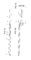
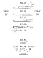
- Figs. 1A to 1C are outline views of a drawing device.
- a guide rail 2 is fixed that extends in the moving direction of the sliding door 1.
- a drawing device main body 4 also elongating is inserted into the guide rail 2 and can move smoothly in the guide rail 2 by door rollers 5 and 6 which are provide at the longitudinal-direction respective ends of the drawing device main body 4.
- the sliding door 1 suspends from the drawing device main body 4.
- the drawing device main body 4 moves in the guide rail 2 in conjunction with movement in opening and closing directions of the sliding door 1.
- the sliding door 1 is connected to the door roller 5 via a position adjusting unit 7.
- the position in the vertical direction and width direction of the sliding door 1 relative to the drawing device main body 4 can be adjusted by the position adjusting unit 7.
- the guide rail 2 has a trigger pin 8.
- This trigger pin 8 is fixed at the position where the sliding door 1 moves in the closing direction and the drawing device main body 4 starts to operate.
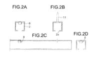
- Figs. 2A to 2D are detail views of the guide rail 2.
- the guide rail 2 has an approximately rectangular cross section and is fixed to the frame by a countersunk screw 11.
- the trigger pin 8 is fixed projecting in the guide rail 2.
- a slit 2a is formed the entire length of the guide rail 2 in the longitudinal direction.
- the door rollers 5 and 6 of the drawing device main body 4 roll on the upper surface of the bottom part of the guide rail 2.
- There is a connecting shaft 5a (see Fig. 1 ) that projects from the door rollers 5 and 6 via the slit 2a for connecting the door rollers 5 and 6 to the sliding door 1.
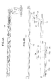
- Figs. 3A to 4B are detail views of the drawing device main body 4.
- Figs. 3A and 3B are plan views of the drawing device main body 4 and Figs. 4A and 4B are vertical cross sectional views of the drawing device main body 4.
- Figs. 3A and 4A illustrate the drawing device main body 4 assembled and Figs. 3B and 4B illustrate the drawing device main body 4 of which main parts are disassembled.
- the drawing device main body 4 has a base 12 elongating in the longitudinal direction of the guide rail 2 and a slider 14 which is slidable in the longitudinal direction relative to the base 12.
- the rotation axes 17, 16 of the door rollers 5 and 6 are fixed at the respective ends of the base 12 in the longitudinal direction and the door rollers 5 and 6 are rotatable on the rotation axes 17, 16.
- a pair of side walls 12a is formed at the respective sides of the base 12 in the width direction for guiding the slider 14.
- a pulling coil spring 15 is provided over between the base 12 and the slider 14 as an elastic member. The slider 14 slides automatically in the base 12 by a biasing force of the pulling coil spring 15.
- a trigger catcher 18 is mounted in the slider 14 for catching the trigger pin 8.
- the trigger catcher 18 is supported at the tip end in the closing direction of a trigger pusher 19 to be rotatable in the horizontal plane.
- a malfunction reset cam 20 is also supported by the trigger pusher 19 to be rotatable in the horizontal plane.
- a locking piece 18b ( Fig. 4B ) and a rotation axis 18a of the trigger catcher 18 pass through an opening 20a of the malfunction reset cam 20 and fit in a trigger catcher guide groove 12b formed in the base 12 and a trigger catcher guide slit 14a formed in the slider 14 to be slidable in the longitudinal direction.
- There is a compression coil spring 21 provided over between the trigger pusher 19 and the slider 14.
- a trigger catcher guide groove 12b is formed, including a straight groove 12b-1 extending in the longitudinal direction and a locking groove 12b-2 bent to one side at the end in the closing direction of the straight groove 12b-1.
- a damper base 22 is fitted therein slidably.
- a pair of damper base guide grooves 12c is formed separated in the longitudinal direction.
- the damper base 22 has a pair of leg parts 22g formed separated in the longitudinal direction. The paired leg parts 22g are fit into the damper base guide grooves 12c.
- the damper base 22 slides in the base 12 in the longitudinal direction as guided by the damper base guide grooves 12c and the paired side walls 12a of the base 12.
- the linear damper 24 has a tubular damper main body 24a and a rod 24b extendable relative to the damper main body 24a. When the rod 24b contracts, there is generated a damping force.
- the rotary damper 25 has a disc-shaped damper main body 25a and a rotation axis 25b rotatable relative to the damper main body 25a. When the rotation axis 25b rotates, there is generated a damping force.
- the rotation axis 25b is connected to a pinion 27 integrally.
- the damper main body 24a of the linear damper 24 and the damper main body 25a of the rotary damper 25 are connected to the damper base 22.
- the rod 24b of the linear damper 24 is connected to the slider 14.
- the slider 14 moves relatively toward the damper base 22, there is generated a damping force of the linear damper 24.
- the rotary damper 25 rotates and there occurs a damping force.
- a damper lock 28 is attached thereto to be rotatable in the vertical plane.
- a lock hole 12d is formed as a damper lock engaging piece for engagement of the damper lock 28 therein.
- Figs. 5A to 5C illustrate the base 12.
- the elongated base 12 has both ends in the longitudinal direction where connecting pieces 12e are formed as connected to the door rollers 5 and 6.
- a wall part 12f is formed to which an end of the pulling coil spring is connected.
- the paired side walls 12a are formed. The paired side walls 12a guide sliding of the slider 14 in the longitudinal direction relative to the base 12 and guide sliding of the damper base 22 in the longitudinal direction relative to the base 12.
- the trigger catcher guide groove 12b is formed having a straight groove 12b-1 extending in the longitudinal direction and a locking groove 12b-2 that is bent to the side at the end in the closing direction of the straight groove 12b-1.
- the locking piece 18b and the rotation axis 18a of the trigger catcher 18 are fit therein.
- a rectangular-shaped lock hole 12d is formed as a damper lock engaging piece that engages with the damper lock.
- the side surface 12d-1 in the direction opposite to the closing direction of the lock hole 12d is inclined in such a manner that the lock hole 12d becomes larger at the bottom of the lock hole 12d than at the top of the lock hole 12d. This is because, as illustrated in Figs. 4A and 4B , fitting of the damper lock 28 in the lock hole 12d is secured even when the slider 14 pushes the rod 24b of the linear damper 24.
- a pair of damper base guide grooves 12c is formed separated in the longitudinal direction.
- the damper base guide grooves 12c are provided for guiding the damper base 22.
- a rack 26 is formed on the side wall of the base 12.
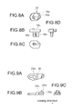
- Figs. 6A to 6F are detail views of the slider 14.
- a trigger catcher guide slit 14a is formed which has a straight slit 14a-1 extending in the longitudinal direction to the closing side and a locking slit 14a-2 bent to the side at the end in the closing direction of the straight slit 14a-1.
- This trigger catcher guide slit 14a corresponds to the trigger catcher guide groove 12b of the base 12 and passes through the slider 14 vertically.
- the trigger catcher guide slit 14a and the trigger catcher guide groove 12b overlap each other. Then, the locking piece 18b of the trigger catcher 18 (see Fig.
- a guide bar 14c is formed for guiding the trigger pusher 19 to be slidable.
- a projection 14d is formed which is fit inside the compression coil spring 21.
- a connection slit 14e is formed which is connected to the tip end of the rod 24b of the linear damper 24.
- a stop ring 24c is mounted on the tip end of the rod 24b. The stop ring 24c and the slider 14 are connected to each other by fitting the stop ring 24c on the connection slit 14e.
- an operation piece 14f is formed that abuts to the damper lock 28 to rotate the damper lock 28 (see Fig. 15B ).
- a recess 14g is formed for allowing rotation of the damper lock 28 by the operation piece 14f.
- Figs. 7A to 7D illustrate the trigger pusher 19.
- a projection 19a is formed that is fit inside the compression coil spring 21.
- a hole 19b is formed.
- the rotation axis 18a of the trigger catcher 18 is fit rotatably.
- a guide groove 19c is formed which is guided by the guide bar 14c of the slider 14.
- a projection 19d is formed that is fit in the straight groove 12b-1 of the base 12 slidably.
- Figs. 8A to 8D illustrate the trigger catcher 18.
- the trigger catcher 18 has a disc-shaped main body 18c, a rotation axis 18a projecting downward from the main body 18c and a locking piece 18b that is provided in adjacent to the rotation axis 18a under the main body.
- a trigger pin insert groove 18d is formed for inserting the trigger pin 8 therein.
- the trigger pin insert groove 18d is surrounded by a wall, in a part of which an inlet part 18e is formed for insertion of the trigger pin 8.
- the locking piece 18b and the rotation axis 18a of the trigger catcher 18 are fit in the trigger catcher guide groove 12b of the base 12.
- Figs. 9A to 9C illustrate the malfunction reset cam 20.
- the malfunction reset cam 20 is supported rotatably, with the trigger catcher 18, by the trigger pusher 19.
- a sector-shaped opening 20a is formed in which the locking piece 18b and the rotation axis 18a of the trigger catcher 18 are fit.
- This sector-shaped opening 20a is formed larger than the locking piece 18b and the rotation axis 18a of the trigger catcher 18 in such a manner that rotation of the trigger catcher 18 relative to the malfunction reset cam 20 can be allowed.
- a slit 20b is formed so that the malfunction reset cam 20 is branched into two vertically.
- a locking piece 20d is formed so as to catch the trigger pin 8.
- the inlet 18e of the trigger pin insert groove 18d of the trigger catcher 18 cannot accommodate the trigger pin 8. Therefore, even if the sliding door 1 is moved in the closing direction and the slider 14 is close to the trigger pin 8, the trigger catcher 18 cannot catch the trigger pin 8. Even in such a case, the upper piece 20c of the malfunction reset cam 20 is bent so that the locking piece 20d of the upper piece 20c catches the trigger pin 8. Therefore, the slider 14 can be reset to the lock position.
- Figs. 10A to 10D illustrate the damper base 22.
- the damper base 22 has a linear damper fixing part 22a where the damper main body of the linear damper 24 is mounted, a damper lock connection bracket 22c provided at the end in the closing direction of the linear damper fixing part 22a and a plate-shaped rotary damper fixing part 22b where the damper main body 25a of the rotary damper 25 is fixed at the side in the direction opposite to the closing direction of the linear damper fixing part 22a.
- a pair of claws 22d is provided bent inward.
- the damper main body 24a of the linear damper 24 is sandwiched between the paired claws 22d in the width direction.
- a pair of end walls 22e is formed between which the damper main body 24a is sandwiched in the longitudinal direction.
- the damper lock connection bracket 22c projects from the linear damper fixing part 22a in the closing direction.
- Connected to the damper lock connection bracket 22c is the damper lock 28 via a spring pin rotatably.
- the damper lock 28 is biased to the lock hole 12d of the base by the spring pin.
- a positioning projection 22f is formed for positioning the damper main body 25a of the rotary damper 25.
- Figs. 11A to 11C illustrate the damper lock 28.
- the damper lock 28 has a through hole 28a formed, into which a spring pin is inserted for connecting the damper lock 28 to the damper base 22.
- the damper lock 28 rotates in the vertical plane around the through hole 28a as a seesaw.
- a slider side hook 28b is formed which engages with a side 14g-1 in an opposite direction to the closing direction of the recess 14g of the slider 14 (see Figs. 6D ).
- a base side hook 28c is formed that engages with a side 12d-1 in an opposite direction to the closing direction of the lock hole 12d of the base 12 (see Figs. 5C ).
- Fig. 12 illustrates the linear damper 24.
- the linear damper 24 has the tubular damper main body 24a and the rod 24b that is extendable relative to the damper main body 24a.
- a piston (not shown) is provided to be connected to the rod 24b.
- the damper main body 24a is filled with oil. With extension and contraction of the rod 24b, the piston moves in the damper main body and viscous resistance of the oil causes a damping force.
- the piston sometimes has an orifice for passage of the oil.
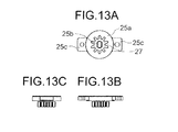
- Figs. 13A to 13C illustrate the rotary damper 25.
- the rotary damper 25 has the disc-shaped damper main body 25a, the rotation axis 25b rotatable relative to the damper main body 25a and the pinion 27 connected to the rotation axis 25b.
- the damper main body 25a is filled with oil.
- the rotation axis 25b is connected to the rotor (not shown). When the rotor rotates in the damper main body 25a, viscous resistance of the oil causes a damping force.
- a pair of overhanging parts 25c is formed which are connected to the damper base 22.
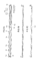
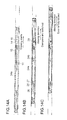
- FIGs. 14A to 14C are plan views of the drawing device and Figs. 15A to 15C are cross sectional views of the drawing device.
- Figs. 14A and 15A illustrate the drawing device which starts to draw
- Figs. 14B and 15B illustrate the drawing device when the dampers are changed
- Figs. 14C and 15C illustrate the drawing device when the door is closed fully.
- the drawing device main body 4 moves in the closing direction together with the sliding door 1.
- the trigger catcher 18 abuts to the trigger pin 8. Then, the trigger catcher 18 rotates to catch the trigger pin 8, the slider 14 becomes slidable relative to the base 12.
- the pulling coil spring 15 is provided between the slider 14 and the base 12, it causes such a pulling force as to slide the slider 14.
- the trigger catcher 18 catches the trigger pin 8 fixed to the guide rail 2, the base 12 moves in the closing direction without moving the trigger catcher 18.
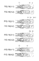
- Figs. 16 (1-1) to (4-2) are detail views in which the trigger catcher 18 rotates to allow sliding.
- Figs. 16 (1-2) (2-2), (3-2), (4-2) illustrate the trigger catcher 18 before it rotates and Figs. 16 (1-1) (2-1), (3-1), (4-1) illustrate the trigger catcher 18 after it has rotated.
- Figs. 16 (1-1) and (1-2) at the top stage are plan views of the trigger pin 8 and the trigger catcher 18, Figs. 16 (2-1) and (2-2) at the second stage from the above are plan views of the trigger catcher 18, Figs. 16 (3-1) and (3-2) at the third stage from the above illustrate a state where the trigger catcher 18 is removed and
- Figs. 16 (4-1) and (4-2) at the bottom stage illustrate a state where the trigger catcher 18 and the malfunction reset cam 20 are removed.
- the malfunction reset cam 20 rotates.
- the open angle of the sector-shaped opening 20a of the malfunction reset cam 20 is larger than the locking piece 18b, the rotation angle of the malfunction reset cam 20 becomes smaller than the trigger catcher 18. Accordingly, if the malfunction reset cam 20 rotates, it does not run off the slider 14.
- the rack 26 provided in the base 12 and the pinion 27 of the rotary damper 25 engage with each other, and the rotary damper 25 rotates.
- the rotation of the rotary damper 25 causes a damping force.
- it is switched to the rotary damper 25 and the rotary damper 25 causes a damping force until the sliding door 1 is closed fully. This makes it possible to prevent occurrence of impact and noise during the full closing operation.
- the pulling force of the pulling coil spring 15 becomes small at a last half of the drawing operation, it does not matter if the damping force generated by the rotary damper 25 is small.
- FIGs. 17A to 17D are plan views of the drawing device and Figs. 18A to 18D are cross sectional views of the drawing device.
- Figs. 17A and 18A illustrate the drawing device when the sliding door is fully closed
- Figs. 17B and 18B illustrate the drawing device when the sliding door starts to open
- Figs. 17C and 18C illustrate the drawing device when the damper lock is fit in the lock hole of the base 12
- Figs. 17D and 18D illustrate the drawing device when the damper base 22 moves integrally with the base 12.
- the rod 24b is completely drawn from the damper main body 24a of the linear damper 24 and the slider 14 moves up to the lock position of the base 12, the trigger catcher 18 and the malfunction reset cam 20 rotate by the elastic force of the compression coil spring 21 and the slider 14 is fixed to the lock position. Then, as the trigger catcher 18 releases the trigger pin 8, the sliding door is moved without operating of the drawing device.
- the drawing device of the present invention may be used to assist closing and opening of the opening/closing body such as folding door, drawer, as well as the sliding door.
- the trigger catcher and the slider are separate members, but they may be combined into one piece.
Landscapes
- Engineering & Computer Science (AREA)
- Mechanical Engineering (AREA)
- Closing And Opening Devices For Wings, And Checks For Wings (AREA)
- Wing Frames And Configurations (AREA)
- Drawers Of Furniture (AREA)
- Vibration Dampers (AREA)
Applications Claiming Priority (1)
| Application Number | Priority Date | Filing Date | Title |
|---|---|---|---|
| JP2010038301A JP4895317B2 (ja) | 2010-02-24 | 2010-02-24 | 引込装置 |
Publications (2)
| Publication Number | Publication Date |
|---|---|
| EP2360336A2 true EP2360336A2 (de) | 2011-08-24 |
| EP2360336A3 EP2360336A3 (de) | 2014-07-09 |
Family
ID=44021804
Family Applications (1)
| Application Number | Title | Priority Date | Filing Date |
|---|---|---|---|
| EP11153303.0A Withdrawn EP2360336A3 (de) | 2010-02-24 | 2011-02-04 | Ziehvorrichtung |
Country Status (5)
| Country | Link |
|---|---|
| US (1) | US8726574B2 (de) |
| EP (1) | EP2360336A3 (de) |
| JP (1) | JP4895317B2 (de) |
| KR (1) | KR101179095B1 (de) |
| CN (1) | CN102162324B (de) |
Cited By (2)
| Publication number | Priority date | Publication date | Assignee | Title |
|---|---|---|---|---|
| WO2018009049A1 (es) * | 2016-07-04 | 2018-01-11 | Rodríguez Rodríguez Óscar | Sistema deslizable de retorno automático para puertas corredizas |
| EP3372116B1 (de) * | 2017-03-07 | 2019-08-14 | King Slide Works Co., Ltd. | Möbel mit einzugsmechanismus |
Families Citing this family (17)
| Publication number | Priority date | Publication date | Assignee | Title |
|---|---|---|---|---|
| US9458656B2 (en) * | 2007-06-13 | 2016-10-04 | Andersen Corporation | Internally power slider with high torque drive system |
| DE102008009046B4 (de) * | 2008-02-13 | 2014-10-02 | Günther Zimmer | Beschleunigungs- und Verzögerungsvorrichtung mit zwei Mitnahmeelementen |
| JP4895318B2 (ja) * | 2010-02-24 | 2012-03-14 | 株式会社中尾製作所 | 引込装置 |
| JP5875329B2 (ja) * | 2011-11-07 | 2016-03-02 | 株式会社ダイケン | 引戸の引き込み装置 |
| DE102012101410A1 (de) * | 2012-02-22 | 2013-08-22 | REMIS Gesellschaft für Entwicklung und Vertrieb von technischen Elementen mit beschränkter Haftung | Kühlschrank |
| CN103422762B (zh) * | 2012-05-20 | 2016-01-20 | 陈明开 | 用于多门左右缓冲开合的导向装置 |
| RU2620753C2 (ru) * | 2013-04-15 | 2017-05-29 | Чжуншань Опике Хардвэа Продакт Ко., Лтд | Предотвращающее выскакивание устройство с верхним колесиком и двумя демпферами |
| CN104110189A (zh) * | 2014-02-27 | 2014-10-22 | 广东冠辉科技有限公司 | 趟门轮件 |
| WO2015129494A1 (ja) * | 2014-02-28 | 2015-09-03 | スガツネ工業株式会社 | 引戸クローザーセット |
| JP2015194795A (ja) * | 2014-03-31 | 2015-11-05 | シャープ株式会社 | 表示装置及び表示方法 |
| GB201411062D0 (en) * | 2014-06-20 | 2014-08-06 | Lama D D Dekani | Improvements in movement control devices |
| TWM493587U (zh) * | 2014-08-05 | 2015-01-11 | Weider Metal Inc | 推拉門緩衝器裝置的閉合位置調整機構 |
| DE102015003428B4 (de) * | 2015-03-17 | 2016-10-20 | Günther Zimmer | Oberer Türbeschlag einer Schiebetür |
| CA2921440A1 (en) * | 2015-07-29 | 2017-01-29 | Assa Abloy New Zealand Limited | A closure mechanism |
| US20180016832A1 (en) * | 2015-09-21 | 2018-01-18 | Oscar RODRIGUEZ RODRIGUEZ | Soft-close system for sliding doors |
| US20190178018A1 (en) * | 2016-08-10 | 2019-06-13 | Oscar RODRIGUEZ RODRIGUEZ | A glass soft-closing system for sliding doors |
| US10292494B1 (en) * | 2017-07-03 | 2019-05-21 | Nan Jeun International Co., Ltd. | Slide rail self-return mechanism |
Citations (3)
| Publication number | Priority date | Publication date | Assignee | Title |
|---|---|---|---|---|
| JP2006200300A (ja) | 2005-01-24 | 2006-08-03 | Tostem Corp | 引戸の引き込み装置 |
| JP2008285933A (ja) | 2007-05-18 | 2008-11-27 | Atom Livin Tech Co Ltd | 引戸のスライドアシスト装置 |
| JP2010038301A (ja) | 2008-08-06 | 2010-02-18 | Toyota Motor Corp | 結合構造 |
Family Cites Families (13)
| Publication number | Priority date | Publication date | Assignee | Title |
|---|---|---|---|---|
| JP3930459B2 (ja) * | 2003-06-30 | 2007-06-13 | 株式会社シモダイラ | 引戸の戸閉装置 |
| DE20315124U1 (de) * | 2003-09-29 | 2004-02-26 | Hettich-Heinze Gmbh & Co. Kg | Selbsteinzug mit Dämpfer für bewegliche Möbelteile |
| KR100831102B1 (ko) * | 2004-01-13 | 2008-05-20 | 가부시키가이샤 무라코시 세이코 | 완충장치 |
| JP4751607B2 (ja) * | 2004-12-20 | 2011-08-17 | 株式会社ニフコ | 自走往動させる機構、引き戸機構、および、引き出し機構 |
| JP4791796B2 (ja) * | 2005-10-27 | 2011-10-12 | 不二ラテックス株式会社 | 緩衝装置 |
| EP1959082A4 (de) * | 2005-11-08 | 2013-10-30 | Nifco Inc | Einziehmechanismus |
| JP5093881B2 (ja) * | 2006-11-13 | 2012-12-12 | 株式会社ニフコ | 摺動補助機構及び引込ユニット |
| JP5109406B2 (ja) * | 2007-02-26 | 2012-12-26 | 中西金属工業株式会社 | 引戸用ブレーキ装置 |
| US7980640B2 (en) * | 2007-11-08 | 2011-07-19 | Jun-Long Yang | Auto-return drawer rail |
| JP5074214B2 (ja) * | 2008-01-17 | 2012-11-14 | 株式会社ニフコ | 引込機構 |
| JP5139873B2 (ja) * | 2008-04-18 | 2013-02-06 | 株式会社ニフコ | ラッチ装置 |
| US8123313B2 (en) * | 2008-06-05 | 2012-02-28 | Illinois Tool Works Inc. | Door motion dampening system |
| JP4895318B2 (ja) * | 2010-02-24 | 2012-03-14 | 株式会社中尾製作所 | 引込装置 |
-
2010
- 2010-02-24 JP JP2010038301A patent/JP4895317B2/ja active Active
- 2010-12-01 KR KR1020100121196A patent/KR101179095B1/ko not_active Expired - Fee Related
-
2011
- 2011-01-21 US US13/011,466 patent/US8726574B2/en not_active Expired - Fee Related
- 2011-02-04 EP EP11153303.0A patent/EP2360336A3/de not_active Withdrawn
- 2011-02-18 CN CN201110042228.3A patent/CN102162324B/zh not_active Expired - Fee Related
Patent Citations (3)
| Publication number | Priority date | Publication date | Assignee | Title |
|---|---|---|---|---|
| JP2006200300A (ja) | 2005-01-24 | 2006-08-03 | Tostem Corp | 引戸の引き込み装置 |
| JP2008285933A (ja) | 2007-05-18 | 2008-11-27 | Atom Livin Tech Co Ltd | 引戸のスライドアシスト装置 |
| JP2010038301A (ja) | 2008-08-06 | 2010-02-18 | Toyota Motor Corp | 結合構造 |
Cited By (2)
| Publication number | Priority date | Publication date | Assignee | Title |
|---|---|---|---|---|
| WO2018009049A1 (es) * | 2016-07-04 | 2018-01-11 | Rodríguez Rodríguez Óscar | Sistema deslizable de retorno automático para puertas corredizas |
| EP3372116B1 (de) * | 2017-03-07 | 2019-08-14 | King Slide Works Co., Ltd. | Möbel mit einzugsmechanismus |
Also Published As
| Publication number | Publication date |
|---|---|
| KR20110097602A (ko) | 2011-08-31 |
| JP4895317B2 (ja) | 2012-03-14 |
| US20110203183A1 (en) | 2011-08-25 |
| KR101179095B1 (ko) | 2012-09-03 |
| EP2360336A3 (de) | 2014-07-09 |
| CN102162324A (zh) | 2011-08-24 |
| CN102162324B (zh) | 2014-06-11 |
| JP2011174271A (ja) | 2011-09-08 |
| US8726574B2 (en) | 2014-05-20 |
Similar Documents
| Publication | Publication Date | Title |
|---|---|---|
| US8726574B2 (en) | Drawing device | |
| EP2360338A2 (de) | Ziehvorrichtung | |
| US8793839B2 (en) | Retracting device | |
| US8459758B2 (en) | Drawer slide auto-close dampening system with reset feature | |
| US9657506B2 (en) | Sliding arrangement | |
| EP3167752B1 (de) | Antriebsvorrichtung für möbel | |
| JP5417603B2 (ja) | 自動引込み装置および引出しガイド | |
| TWI532452B (zh) | 驅動機構 | |
| US20180100338A1 (en) | Ejection device for a movable furniture part | |
| US10172460B2 (en) | Retracting device for furniture parts | |
| US20180094457A1 (en) | Ejection device for a movable furniture part | |
| CN108348069B (zh) | 用于可运动的家具部件的拉入设备 | |
| EP2752133B1 (de) | Einzugvorrichtung für Schiebelemente | |
| US9648950B2 (en) | Device for moving a movable furniture part in an opening direction in relation to a basic furniture structure of an item of furniture | |
| US20180100329A1 (en) | Push-out device for a movable furniture part | |
| JP2014062391A (ja) | 引込み装置ユニット | |
| KR20180036511A (ko) | 개폐 장치 | |
| JP2014012955A (ja) | ソフトクローズ装置 | |
| JP6594828B2 (ja) | 制動装置、自動移動装置および建具 | |
| HK1179672B (en) | Pull-in device |
Legal Events
| Date | Code | Title | Description |
|---|---|---|---|
| PUAI | Public reference made under article 153(3) epc to a published international application that has entered the european phase |
Free format text: ORIGINAL CODE: 0009012 |
|
| AK | Designated contracting states |
Kind code of ref document: A2 Designated state(s): AL AT BE BG CH CY CZ DE DK EE ES FI FR GB GR HR HU IE IS IT LI LT LU LV MC MK MT NL NO PL PT RO RS SE SI SK SM TR |
|
| AX | Request for extension of the european patent |
Extension state: BA ME |
|
| PUAL | Search report despatched |
Free format text: ORIGINAL CODE: 0009013 |
|
| AK | Designated contracting states |
Kind code of ref document: A3 Designated state(s): AL AT BE BG CH CY CZ DE DK EE ES FI FR GB GR HR HU IE IS IT LI LT LU LV MC MK MT NL NO PL PT RO RS SE SI SK SM TR |
|
| AX | Request for extension of the european patent |
Extension state: BA ME |
|
| RIC1 | Information provided on ipc code assigned before grant |
Ipc: E05F 1/16 20060101ALI20140605BHEP Ipc: E05F 3/14 20060101AFI20140605BHEP |
|
| STAA | Information on the status of an ep patent application or granted ep patent |
Free format text: STATUS: THE APPLICATION IS DEEMED TO BE WITHDRAWN |
|
| 18D | Application deemed to be withdrawn |
Effective date: 20150110 |