EP2354591A2 - Schubkette mit Vorspannfeder zur Verhinderung des Knickens - Google Patents
Schubkette mit Vorspannfeder zur Verhinderung des Knickens Download PDFInfo
- Publication number
- EP2354591A2 EP2354591A2 EP11153469A EP11153469A EP2354591A2 EP 2354591 A2 EP2354591 A2 EP 2354591A2 EP 11153469 A EP11153469 A EP 11153469A EP 11153469 A EP11153469 A EP 11153469A EP 2354591 A2 EP2354591 A2 EP 2354591A2
- Authority
- EP
- European Patent Office
- Prior art keywords
- drive chain
- spring
- links
- chain
- compressive force
- Prior art date
- Legal status (The legal status is an assumption and is not a legal conclusion. Google has not performed a legal analysis and makes no representation as to the accuracy of the status listed.)
- Withdrawn
Links
- 239000000463 material Substances 0.000 claims description 10
- 238000000034 method Methods 0.000 claims description 7
- 238000000926 separation method Methods 0.000 claims description 5
- 230000007423 decrease Effects 0.000 claims description 2
- 239000013013 elastic material Substances 0.000 claims 1
- 230000036316 preload Effects 0.000 description 3
- 230000000284 resting effect Effects 0.000 description 3
- 230000013011 mating Effects 0.000 description 2
- 210000000887 face Anatomy 0.000 description 1
Images


Classifications
-
- F—MECHANICAL ENGINEERING; LIGHTING; HEATING; WEAPONS; BLASTING
- F16—ENGINEERING ELEMENTS AND UNITS; GENERAL MEASURES FOR PRODUCING AND MAINTAINING EFFECTIVE FUNCTIONING OF MACHINES OR INSTALLATIONS; THERMAL INSULATION IN GENERAL
- F16G—BELTS, CABLES, OR ROPES, PREDOMINANTLY USED FOR DRIVING PURPOSES; CHAINS; FITTINGS PREDOMINANTLY USED THEREFOR
- F16G13/00—Chains
- F16G13/18—Chains having special overall characteristics
- F16G13/20—Chains having special overall characteristics stiff; Push-pull chains
-
- B—PERFORMING OPERATIONS; TRANSPORTING
- B05—SPRAYING OR ATOMISING IN GENERAL; APPLYING FLUENT MATERIALS TO SURFACES, IN GENERAL
- B05C—APPARATUS FOR APPLYING FLUENT MATERIALS TO SURFACES, IN GENERAL
- B05C17/00—Hand tools or apparatus using hand held tools, for applying liquids or other fluent materials to, for spreading applied liquids or other fluent materials on, or for partially removing applied liquids or other fluent materials from, surfaces
- B05C17/005—Hand tools or apparatus using hand held tools, for applying liquids or other fluent materials to, for spreading applied liquids or other fluent materials on, or for partially removing applied liquids or other fluent materials from, surfaces for discharging material from a reservoir or container located in or on the hand tool through an outlet orifice by pressure without using surface contacting members like pads or brushes
- B05C17/01—Hand tools or apparatus using hand held tools, for applying liquids or other fluent materials to, for spreading applied liquids or other fluent materials on, or for partially removing applied liquids or other fluent materials from, surfaces for discharging material from a reservoir or container located in or on the hand tool through an outlet orifice by pressure without using surface contacting members like pads or brushes with manually mechanically or electrically actuated piston or the like
- B05C17/0116—Hand tools or apparatus using hand held tools, for applying liquids or other fluent materials to, for spreading applied liquids or other fluent materials on, or for partially removing applied liquids or other fluent materials from, surfaces for discharging material from a reservoir or container located in or on the hand tool through an outlet orifice by pressure without using surface contacting members like pads or brushes with manually mechanically or electrically actuated piston or the like characterised by the piston driving means
Definitions
- Motion-transmitting drive chains are well known. Such chains are alternately known as or referred to as push chains, drive chains, and thrust chains. Regardless of what they are called, motion-transmitting drive chains are able to transmit an axial compressive load as well as exert a tensile force. Common chain on the other hand is incapable of transmitting a compressive load and is only able to exert a tensile force.
- Motion-transmitting drive chains and common chains are both made up of successive, flexibly-connected links which are joined to each other by pins.
- the links are freely able to rotate around the pins in both directions.
- the links of a motion-transmitting drive chain are able rotate in only one direction.
- the links of a drive chain are urged to rotate in the opposite direction, the chain becomes rigid and thereafter able to transmit a compressive axial load.
- a problem with prior art drive chains is their susceptibility to buckling, if the line of action of a compressive force tends to rotate the links in the wrong direction or if the links are not sufficiently loaded to keep them locked.
- a drive chain that pre-loads the links of a drive chain such that they are less susceptible to buckling would be an improvement over the prior art.
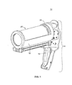
- FIG. 1 is a perspective view of a rodless dispenser for extrudable materials
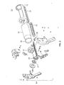
- FIG. 2 is an exploded view of the dispenser shown in FIG. 1 ;
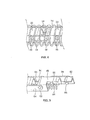
- FIG. 3 is a perspective view of an isolated portion of a drive chain
- FIG. 4 is a side view of the drive chain shown in FIG. 3 ;
- FIG. 5 is an isolated view of a link body of a drive chain shown in FIG. 4 ;
- FIG. 6 depicts a coil spring wrapped around the outside of a drive chain to provide a compressive bias force
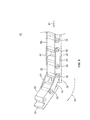
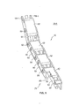
- FIG. 7 is a side view of the dispenser shown in FIG. 1 , with the housing removed to reveal a drive chain through the interior of a coil spring;
- FIG. 8 depicts an alternate embodiment of a drive chain
- FIG. 9 depicts another alternate embodiment of a drive chain
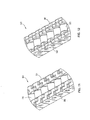
- FIG. 10 depicts two alternate embodiments of a drive chain 90 and 92;
- FIGS. 11 and 12 are isolated views of the links of the alternate embodiments depicted in FIG. 10 .
- FIG. 13 is an exploded view of two link bodies depicted in FIG. 11 ;
- FIG. 14 is an exploded view of two link bodies shown in FIG. 12 ;
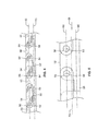
- FIG. 15 is a side view of the chain 90 shown in FIG. 10 and FIG. 11 ;
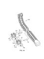
- FIG. 16 is a side view of the chain 92 shown in FIG. 12 and in FIG. 10 ;
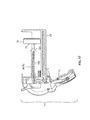
- FIG. 17 is a side view of a push chain used in rodless dispenser for extrudable materials.
- FIG. 1 is a perspective view of a rodless dispenser for extrudable materials 10.
- the dispenser 10 is comprised of a housing 12 attached to a handle assembly 14.
- a reciprocating trigger 16 drives a chain sprocket located inside the handle assembly 14. Rotation of the sprocket by actuating the trigger 16 causes a drive chain to be pulled from a chain magazine 29 and driven into the back side of a piston18.
- the piston 18 drives a second piston inside of a tube 20 of extrudable material.
- FIG. 2 is an exploded view of the dispenser 10 shown in FIG. 1 showing the drive chain 50, among other things.
- the drive chain 50 is a motion-transmitting drive chain. It has a forward or first end 26 rotatably coupled to the backside of the piston 18. It also has a rearward or second end 28 inside a magazine 29 that stores the chain.
- the drive chain 50 rotates on, and is driven by, a sprocket 51 which is itself driven by the trigger assembly 16.
- a description of the dispenser 10, its components and operation is provided in a U.S. patent application serial number that was filed January 8, 2010, having U.S. application number 12/684,597 and which is entitled, Rodless Dispenser. The contents of application serial number 12/684,597 , is incorporated herein by reference in its entirety.
- FIG. 3 is a perspective view of an isolated portion of a drive chain 50.
- the drive chain 50 is comprised of a link body 52. Holes are drilled or otherwise formed in the link body 52, just below the top surface 76, which accept pins 56 that attach the link bodies 52 to each other via link connectors 54.
- the link connectors 54 and the pins 56 are sized, shaped and arranged to allow the link connectors 54 and therefore adjacent link bodies 52 to rotate around the pins 56.
- the link bodies 52 are thus able to rotate around the pins 56, in at least one direction because of one or more interlocking projections 58, which extend away from the link bodies 52 parallel to the axis of the chain 50.
- the projections 58 are therefore considered to be axially-extending interlocking projections.
- each link body 52 has an elongated projection 58 that extends away from the link body 52 at one end thereof.
- a projection 58 from one link body 52 abuts and interlocks with an adjacent link body 52 such that the link body 52 and the link connectors 54 are able to rotate around the pins 56 in only one direction.
- the link bodies 52 and projections 58 permit the links (link bodies, pins and link connectors) to rotate in only a clockwise direction 60 as shown.
- a bias or pre-load compressive force 61 in the axial direction i.e., lengthwise down the axis of the chain 50 can prevent the chain links from buckling, i.e., rotating around each other, if the force 61 is property applied.
- FIG. 4 is a side view of the drive chain shown in FIG. 3 .
- FIG. 5 is an isolated view of a link body 52 shown in FIG. 4 .
- reference numeral 62 identifies a geometric plane that extends into the plane of FIG. 4 and FIG. 5 and which is co-planar or substantially co-planar with the geometric axes of rotation 64 for each pin 56 shown in FIG. 4 and FIG. 5 .
- the geometric axes of rotation 64 i.e., the geometric centers of the pins 56 are therefore co-planar or substantially co-planar with the first geometric plane 62.
- Reference numeral 66 identifies a second geometric plane which is displaced "vertically" from the first plane 62 as the two planes are shown in the figures.
- the second plane 66 is also parallel to the first plane 62 and cuts horizontally through the geometric centerline of the projections 58 shown in the figure.
- the distance separating the first plane 62 from the second plane 66 is considered a separation distance of the pins 56 from the projections 58.
- reference numeral 68 identifies a vector that represents a compressive force applied to the links 50 from a source not visible in FIG. 5 .
- the force/vector 68 has a line of action 70 located between the first plane 62 and the second plane 66.
- the application of the force 68 on the second-plane 66 side of the first plane 62 results in a clockwise torque around the pins 56 due to the fact that the line of action 70 of the force 68 is vertically separated from the centerline 62 of the pins 56 by a non-zero distance.
- the force 68 has a line of action on the second-plane side of the first plane 62 such that the force 68 tends to rotate the link bodies 52 clockwise around the axes of rotation 64. Clockwise rotation of the link bodies 52 around the axes 64 will urge the projections 58 of a link body 52 into an adjacent link body 52. Driving a projection on one link body 52 into an adjacent link body causes the axial aligned projections 58 to interlock adjacent links. Driving the projections 58 into the link bodies will therefore prevent or tend to prevent the drive chain from buckling, i.e., rotating in the opposite direction due to the absence of a force to keep the links locked together.
- the force represented by the vector 68 is preferably supplied to a drive chain by one or more types of springs wrapped around the chain's links or contained within the links of the drive chain 50.
- FIG. 6 depicts a coil spring 74 having a substantially circular cross section, wrapped around the outside of a drive chain 50, such the drive chain 50 shown in FIG. 2 as well as a drive chain comprised of links 50 shown in FIGS. 3 , 4 and 5 .
- a coil spring 74 having a substantially circular cross section, wrapped around the outside of a drive chain 50, such the drive chain 50 shown in FIG. 2 as well as a drive chain comprised of links 50 shown in FIGS. 3 , 4 and 5 .
- the shape and dimensions of the spring need to be selected to allow the spring to freely pass through the interior of the spring in order to allow the spring and chain links to move independently of each other.
- FIG. 7 is a side view of the dispenser 10 shown in FIG. 1 albeit with the housing 12 removed to reveal how the drive chain 50 passes through the interior of the coil spring 74.
- a first forward end 75 of the spring 74 is attached to the back side of the aforementioned piston 18.
- a second, rearward end 77 is attached to a stanchion part of the dispenser 10, an example of which includes a hook (not visible in FIG. 7 ) as part of the handle assembly 14.
- Piston movement toward the right side ofFIG.7 increases tension in the spring 74. Piston movement to the left side of FIG. 7 decreases tension in the spring 74.
- the compressive force 68 on the chain 50 that is identified in FIG. 6 by reference numeral 68 is provided by attachment of the forward end 75 of the spring 74 to the back side of the piston 18 at an attachment point 79. The location of the spring attachment point 79 is selected so that the line of action 64 of the spring's compressive force tends to rotate the links of the chain 50 in a counter-clockwise (as shown) direction, i.e., such that the compressive force acts through a line of action on the projection 58 side of the pins' axes of rotation 64.
- the chain 50 is configured to rotate around a handle-mounted sprocket as shown but not rotate in the opposite direction. Properly selecting the location of the spring attachment point 79 and the spring force line of action 64 will therefore cause the axial aligned projections of each link in the chain 50 to lock to an adjacent link as described above.
- the central axes of the pins 56 of the chain 50 lie in a geometric plane identified by reference numeral 62.
- the axially-aligned projections 92 lie in or parallel to the first plane 62 as well as a second geometric plane identified by reference numeral 64 and which passes through the projections 92 of the spring 50.
- the application of a compressive force on the second-plane 64 side of the first plane 62 will cause the links to rotate the axial projections 58 of each link body, against a link body of an adjacent link.
- FIG. 8 depicts an alternate embodiment of a drive chain 50-1 having a spring that applies a pre-load bias force to help prevent the drive chain from buckling.
- each link body 52 has a first or top side 76 that is substantially planer and smooth.
- a second, underside 78 is formed to have an open passageway 80.
- the open passageway 80 of each link body form an elongated passageway that can receive an elongated elastic rubber band or elastic string 82.
- a compressive force exerted by the elastic string 82 will be applied "below” the pins 56 as shown, and therefore "below” the pins' axes of rotation.
- Applying a compressive load as shown in FIG. 8 will cause the link bodies 52 to rotate in a clockwise direction (when viewed from the left) such that the interlocking projections 58-1 will abut and lock against adjacent link bodies 52.
- Spring motors are spring-powered retraction devices. Spring motors are commonly used to retract seat belts, among other things. In an alternate embodiment of the chain shown in FIG. 8 , the elastic spring 82 is replaced by an appropriately-sized spring motor.
- FIG. 9 depicts an alternate embodiment of a motion-transmitting drive chain that is pre-loaded or pre-biased by a spring.
- a relatively small-diameter coil spring 84 extends through the passageway 80 in the underside or bottom 78 of the chain 50.
- FIG. 10 depicts two alternate embodiments of a drive chain 90 and 92, the links of which are configured to rotate in a first direction but not in an opposite second direction.
- the drive chains depicted in FIG. 10 are capable of being used with or without a bias spring described above to prevent their buckling.
- a first embodiment 90 and a second embodiment 92 are comprised of link bodies 94 and 96 respectively, link connecting pins 98 not visible in FIG. 10 , and bearings 100, through which the connecting pins 98 extend.
- the chain embodiments depicted in FIG. 10 do not require the link connectors 54 described above and depicted in FIG. 3 , et al.
- FIGS. 11 and 12 are isolated views of the links of the alternate embodiments depicted in FIG.10 .
- Both chains are configured to enable their respective link bodies 92 and 94 to rotate in one direction but to interlock against each other when the chains or individual link bodies are urged to rotate in an opposite, second direction.
- the link bodies of both chains are sized, shaped and arranged as shown to form knuckle joints.
- the chain links formed from such knuckle joints do not require a separate link connector, such as the link connector 54 described above and depicted in the figures.
- Knuckle joints are themselves well known.
- One such joint is shown and described in U.S. patent no. 4,929,113 , which was issued to Sheu and entitled "Knuckle Joint.”
- the teachings of Sheu are incorporated herein by reference, at least with regard to the structure and operation of a knuckle joint.
- a knuckle joint comprised of two inter-engaging pieces.
- a first piece is formed to have two, spaced-apart and side-by-side projections that enter a mating jaw.
- the jaw or second piece is also comprised of two, spaced-apart side-by-side projections of a second piece, however, the space between the side-by-side projections of the jaw are wider than the space between the side-by-side projections of the first piece.
- Both pairs of projections on each piece have a hole or an "eye" through which a pin member can be inserted and around which the pieces will rotate. Stated another way, the pin passes through the eyes formed in the two projections of the first piece, and through the two eyes of the mating projections of the second piece. Unless there is some external limiter, a knuckle joint can be pivotally rotated in both directions around the pin.
- FIG. 13 is an exploded view of two individual link bodies 94 of the chain 90 depicted in FIG. 11 .
- Each link body 94 is comprised of the aforementioned first and second pieces, one being a knuckle joint jaw.
- a complete knuckle joint is formed when the second or jaw end 99 of one link body 94 is joined to the first end 97 of a second link body 94 and a connection pin 98 is inserted into the eyes formed in all of the projections.
- a bearing 100 keeps the first and second pieces aligned within the jaws.
- the two projections of the narrow end identified by reference numeral 97 are sized, shaped, and arranged to freely slide within the interior walls of the jaw formed by two projections identified by reference numeral 99.
- a bearing sleeve 100 is sized, shaped, and arranged to fit within the interior walls of the narrow end projections 97.
- a similar bearing 98 fits within the internal space of the jaw projections 99.
- Top “corners” 103 of the jaw portion 99 are rounded. Directly below the rounded corners 103 the corners 95 are squared off as shown. The rounded shoulders 103 allow the link bodies 94 to rotate in a counter-clockwise direction around each bearing 98, however, when the link bodies 94 are urged in a clockwise direction around the bearings 98, the squared-off corners 95 but up against opposing faces 105 on an adjacent link body 94.
- the chain 90 shown in FIG.13 as well as FIG. 11 and FIG. 10 is thus able to rotate in one direction (as shown, clockwise around the pins 98) but not the other.
- FIG. 14 is an exploded view of two link bodies 96 shown in FIG. 12 .
- the link bodies 96 shown in FIG. 17 have an inclined or slanted leading side that terminates in a lower rounded lower shoulder 109 best seen FIG. 16 .
- the rounded lower shoulder 109 permits the link bodies 96 to rotate around the bearings 98 whereas the squared-off upper corners interlock opposing corners 111 on an adjacent link body thus preventing the chain 96 from rotating in a clockwise direction as shown but allowing it to rotate in a counter-clockwise direction.
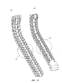
- FIG. 15 is a side view of the chain 90 shown in FIG. 10 and FIG.11 . It is important to note that the link bodies 94 are sized, shaped, and arranged such that when the chain 90 is resting, i.e. without any compressive load and, as shown in the figure, the chain has an upward or convex-shaped bow as shown. Stated another way, the center portion of the chain length deflects "upwardly" (as shown) from a horizontal reference line 120.
- FIG. 16 is a side view of the chain 92 shown in FIG. 12 and in FIG. 10 .
- the link bodies 96 are sized, shaped, and arranged such that it when the chain 92 is resting as shown, it too has a slight upward (as shown) bow giving the chain a an upward or convex shape relative to a horizontal reference line 120.
- the convex shape of the chains at rest is important when a push chain or motion-transmitting drive chain is used to drive a load that will exert a torque on the chain that will tend to bend the chain downwardly, (as shown in the figures) such as a when a push chain is used in a rodless dispenser for extrudable materials shown in FIG. 17 .
- FIG. 17 one of the aforementioned push chains 90 or 92 is shown at rest in a rodless dispenser for extrudable materials.
- the push chain exerts a compressive force on the back side 75 of a combination piston and fixed piston rod 18 in order to drive extrudable material from a tube of extrudable material, not shown.
- the piston rod is located on the back side 75 of the piston such that an axial compressive force exerted on the piston 18 has a line of action through the piston that is below the center line of the piston but "above" the axis of rotation of the connecting pins holding the chain links together.
- the links will remain locked against each other (and the chain locked straight) as long as the axial reactive force from the piston has a line of action that is also above the axis of rotation of the pins that hold the chain link bodies together.
- a reactive torque 124 could deflect the center part of the chain to an extent where a reactive axial force from the piston rod acted on a line below chain's connecting pins. Compressive force that acts on a line below the link pins axis or rotation will cause the links to unlock, i.e., rotate.
- the resting curve shown in FIG. 17 is thus important to maintain the chain's locked state if the chain is subjected to a reactive torque.
- a method of operating the drive chain is preferably comprised of applying a compressive force to the links in order to cause the links to rotate in a direction by which the links and the interlocking projections engage each other.
- the method of applying that compressive force is preferably a step of applying the compressive force as part of retracting the drive chain.
- a mechanism by which a compressive force is applied to a spring can apply the compressive force such that the line of action the compressive force is actually outside the link body 52.
- Such a mechanism would include as arm other projection extending away from the link body 52.
- the spring 74 has a second or rearward end 77 attached to a point that is fixed in space relative to the spring and chain.
- a spring that provide a bias to a drive chain can also be connected to the chain, albeit toward the rearward end of the chain such that the spring is maintained in tension.
- a spring that exerts a bias force on the chain also acts to retract the chain into a chain magazine 29.
Landscapes
- Engineering & Computer Science (AREA)
- Mechanical Engineering (AREA)
- General Engineering & Computer Science (AREA)
- Devices For Conveying Motion By Means Of Endless Flexible Members (AREA)
Applications Claiming Priority (1)
| Application Number | Priority Date | Filing Date | Title |
|---|---|---|---|
| US12/703,565 US8336286B2 (en) | 2010-02-10 | 2010-02-10 | Push chain with a bias spring to prevent buckling |
Publications (1)
| Publication Number | Publication Date |
|---|---|
| EP2354591A2 true EP2354591A2 (de) | 2011-08-10 |
Family
ID=43901128
Family Applications (1)
| Application Number | Title | Priority Date | Filing Date |
|---|---|---|---|
| EP11153469A Withdrawn EP2354591A2 (de) | 2010-02-10 | 2011-02-07 | Schubkette mit Vorspannfeder zur Verhinderung des Knickens |
Country Status (3)
| Country | Link |
|---|---|
| US (1) | US8336286B2 (de) |
| EP (1) | EP2354591A2 (de) |
| CN (1) | CN102146983B (de) |
Cited By (1)
| Publication number | Priority date | Publication date | Assignee | Title |
|---|---|---|---|---|
| US10935106B2 (en) | 2018-06-14 | 2021-03-02 | Serapid, Inc. | Block chain with monolithic links |
Families Citing this family (19)
| Publication number | Priority date | Publication date | Assignee | Title |
|---|---|---|---|---|
| WO2011152265A1 (ja) * | 2010-05-31 | 2011-12-08 | 独立行政法人産業技術総合研究所 | 直動伸縮アーム機構および当該直動伸縮アーム機構を備えたロボットアーム |
| US20110302843A1 (en) * | 2010-06-11 | 2011-12-15 | Dallmann Brian D | Window drive with back-curving chain |
| US8695320B2 (en) * | 2011-02-04 | 2014-04-15 | Zike, Llc | Non-back-bending chain |
| CN103161819B (zh) * | 2012-02-27 | 2015-04-29 | 联想(北京)有限公司 | 铰链装置和包括其的电子设备 |
| EP2909497A1 (de) | 2012-10-19 | 2015-08-26 | Renold PLC | Kette |
| JP6000807B2 (ja) * | 2012-11-05 | 2016-10-05 | 株式会社メタコ | スクリーン装置のスライドガイド枠部 |
| US8919617B2 (en) * | 2012-11-16 | 2014-12-30 | Thomas S. Foley | Caulk gun with expansion drive |
| ES2547255T3 (es) * | 2013-05-03 | 2015-10-02 | Iwis Antriebssysteme Gmbh & Co. Kg | Cadena inflexible en una dirección |
| US9557005B2 (en) * | 2014-05-23 | 2017-01-31 | Roger Neil Rovekamp | Planar non-compressible rigidizable chain assembly |
| US9309764B1 (en) * | 2015-07-28 | 2016-04-12 | Charles M. Schloss | Method for limiting articulation of a chain joint using a chain link extension of a chain assembly |
| FR3043747B1 (fr) * | 2015-11-16 | 2017-12-22 | Serapid France | Maillon de chaine rigide et chaine rigide equipee d'un tel maillon |
| US10343183B2 (en) * | 2016-12-21 | 2019-07-09 | Stoneridge Kitchen & Bath Llc | Glue gun |
| FR3061753B1 (fr) * | 2017-01-10 | 2019-05-31 | Serapid - France | Dispositif de chaine de poussee |
| FR3072374B1 (fr) * | 2017-10-17 | 2022-12-30 | Serapid France | Dispositif elevatoire par poussee |
| CN110038775B (zh) * | 2018-01-15 | 2024-11-26 | 重庆弘愿工具(集团)有限公司 | 一种填缝工具 |
| WO2021021780A1 (en) | 2019-07-29 | 2021-02-04 | Waters Technologies Corporation | Link chain, chain system and method |
| JP7450904B2 (ja) * | 2019-09-04 | 2024-03-18 | 下西技研工業株式会社 | ヒンジ及びヒンジを備える折り畳み可能な機器 |
| JP7664383B2 (ja) * | 2021-05-26 | 2025-04-17 | 株式会社メタコ | スクリーン装置 |
| CN114941692A (zh) * | 2022-07-02 | 2022-08-26 | 上海冶成国际贸易有限公司 | 一种多用途旋转定形收纳链杆 |
Citations (1)
| Publication number | Priority date | Publication date | Assignee | Title |
|---|---|---|---|---|
| US4929113A (en) | 1989-05-30 | 1990-05-29 | Sheu Yin Ping | Knuckle joint |
Family Cites Families (63)
| Publication number | Priority date | Publication date | Assignee | Title |
|---|---|---|---|---|
| US1276117A (en) * | 1917-06-13 | 1918-08-20 | Rogers Motor Lock Company | Flexible armored conduit. |
| US1591693A (en) * | 1925-01-15 | 1926-07-06 | Atz Robert | Spraying machine |
| US2045261A (en) * | 1935-02-18 | 1936-06-23 | Harry W Clute | Push-pull link transmission |
| GB462422A (en) | 1936-04-06 | 1937-03-09 | Harry William Clute | Push-pull link transmission |
| US3031066A (en) * | 1959-01-29 | 1962-04-24 | John M Leach | Swinging tray conveyors |
| US3051264A (en) * | 1960-10-14 | 1962-08-28 | Robert L Batchelor | Lubrication system and method for chain conveyor |
| US3782598A (en) * | 1970-05-15 | 1974-01-01 | N Basa | Dispenser device |
| FR2134196B1 (de) * | 1971-04-26 | 1975-04-18 | Haut Rhin Manufacture Machines | |
| FR2258342B1 (de) * | 1974-01-17 | 1978-04-21 | Sietam | |
| US4154153A (en) * | 1976-02-05 | 1979-05-15 | Stickle Daniel T | Drive mechanism for a mechanized taco shell fryer |
| GB2076473B (en) | 1980-05-23 | 1983-06-29 | So Shun | Extruder for food mixtures |
| US4318499A (en) * | 1980-08-18 | 1982-03-09 | Hamilton Joel A | Retainer and propulsion apparatus carried in a self-contained handle for use with a removable cartridge |
| DE3513880A1 (de) | 1985-04-17 | 1986-10-23 | Josef 8261 Oberbuch Mayer | Geraet zum auspressen plastischer massen |
| IT208046Z2 (it) * | 1986-09-15 | 1988-03-31 | Tecno Mobili E Forniture Per A | Organo passocavo flessibile a snodi bidirezionali. |
| DE8806871U1 (de) | 1988-05-26 | 1989-06-22 | Wilcke, Hans, 53498 Bad Breisig | Schubkette mit zugehörigem Antrieb |
| DE3908265A1 (de) * | 1989-03-14 | 1990-09-20 | Leybold Ag | Chargiervorrichtung fuer schmelzanlagen |
| US5064098A (en) * | 1990-02-23 | 1991-11-12 | Physical Systems, Inc. | Dual component dispenser gun |
| CN2113378U (zh) * | 1992-01-31 | 1992-08-19 | 吴盈进 | 链条 |
| CN2112722U (zh) * | 1992-02-20 | 1992-08-12 | 吴俊德 | 无链轴的脚踏车链条 |
| DE4216541C2 (de) | 1992-05-19 | 1995-02-16 | Sigismund Laskowski | Mehrfach verwendbarer Dosierspender |
| CN2134538Y (zh) * | 1992-07-22 | 1993-05-26 | 罗自广 | 一种链条 |
| US5305358A (en) * | 1992-12-17 | 1994-04-19 | Westinghouse Electric Corp. | Control rod drive handling equipment |
| US5295614A (en) * | 1992-12-22 | 1994-03-22 | Chang Peter J Y | Double reduction gear for dispensing gun |
| US5323931A (en) * | 1993-02-08 | 1994-06-28 | Prince Castle Inc. | Dispenser for extrudable material including dispensing from collapsible containers |
| ZA969518B (en) | 1995-11-14 | 1997-09-08 | Fata Hunter Inc | Chain caster for metal sheets without fins and continuous width adjustment. |
| USRE38555E1 (en) * | 1995-11-14 | 2004-07-13 | Hunter Douglas Industries, B.V. | Continuous chain caster and method |
| US6354793B1 (en) * | 1996-07-03 | 2002-03-12 | Gammerler Ag | Stack grasper for sheet-like products and method of palletizing using a stack grasper |
| US6109424A (en) * | 1997-03-20 | 2000-08-29 | Fori Automation, Inc. | Chassis/body marriage lift machine |
| DE19805157A1 (de) | 1998-02-10 | 1999-08-19 | Schlachter | Kette für einen Schubkettenantrieb und deren Verwendung |
| US5970701A (en) * | 1998-03-02 | 1999-10-26 | Roden; Garey | Restricted movement chain and universal link therefor |
| FR2780472B1 (fr) | 1998-06-24 | 2000-09-08 | Serapid France | Dispositif d'entrainement des maillons d'une chaine de poussee |
| DE29818339U1 (de) | 1998-10-14 | 2000-02-24 | Aumüller Aumatic GmbH, 86167 Augsburg | Kettenschubantrieb |
| FR2786476B1 (fr) * | 1998-11-30 | 2001-02-23 | Serapid France | Colonne elevatrice de charges |
| US6148925A (en) * | 1999-02-12 | 2000-11-21 | Moore; Boyd B. | Method of making a conductive downhole wire line system |
| US6360810B1 (en) * | 1999-02-23 | 2002-03-26 | Ati Properties, Inc. | Vacuum induction melting system |
| KR100394502B1 (ko) * | 1999-04-15 | 2003-08-14 | 가부시끼가이샤 도시바 | 콘베이어 장치 |
| DE29913063U1 (de) * | 1999-07-30 | 2000-02-17 | Igus Spritzgußteile für die Industrie GmbH, 51147 Köln | Energiezuführungskette |
| DE19955311C2 (de) * | 1999-11-17 | 2003-12-24 | Jungheinrich Ag | Antriebssystem für ein Flurförderzeug |
| DE19955312B4 (de) * | 1999-11-17 | 2005-10-27 | Jungheinrich Ag | Antriebssystem für Flurförderzeuge |
| US6386401B1 (en) * | 2000-01-31 | 2002-05-14 | Prince Castle Inc. | Dispenser for extrudable material |
| JP2001254796A (ja) | 2000-03-14 | 2001-09-21 | Daido Kogyo Co Ltd | プッシュチェーンを用いた押圧力伝達装置 |
| JP4683704B2 (ja) * | 2000-10-23 | 2011-05-18 | 東芝エレベータ株式会社 | 乗客コンベア装置 |
| FR2826422B1 (fr) * | 2001-06-26 | 2003-11-14 | Serapid France | Actionneur lineaire a courroie |
| US6321945B1 (en) * | 2001-07-13 | 2001-11-27 | Gaston Girouard | Compact motor driven dispenser |
| US6981621B2 (en) * | 2002-01-29 | 2006-01-03 | Zeev Brandeis | Caulking gun |
| JP2003314630A (ja) | 2002-04-24 | 2003-11-06 | Daido Kogyo Co Ltd | プッシュチエーン |
| DE10240854A1 (de) * | 2002-09-04 | 2004-03-18 | Still Gmbh | Flurförderzeug mit einem auf einer Rollbahn angeordneten Batterieblock |
| JP2004108473A (ja) | 2002-09-18 | 2004-04-08 | Daido Kogyo Co Ltd | プッシュチエーン |
| US20040177934A1 (en) * | 2003-03-10 | 2004-09-16 | The Chamberlain Group, Inc. | Garage door movement apparatus |
| NL1025757C2 (nl) | 2004-03-18 | 2005-09-20 | Fransiscus Petrus Mar Kolsters | Positioneringslift. |
| JP2005282745A (ja) | 2004-03-30 | 2005-10-13 | Daido Kogyo Co Ltd | プッシュチェーン動力伝達装置 |
| DE202004006624U1 (de) | 2004-04-26 | 2005-08-04 | Motus Engineering Gmbh & Co. Kg | Selbstversteifende aufwickelbare Schubkette |
| JP2005337346A (ja) | 2004-05-26 | 2005-12-08 | Daido Kogyo Co Ltd | プッシュチェーン動力伝達装置 |
| GB0415501D0 (en) | 2004-07-09 | 2004-08-11 | Radius Engineering Ltd | Forming means |
| US7331425B2 (en) * | 2004-07-09 | 2008-02-19 | Gm Global Technology Operations, Inc. | Lift machine |
| US8235254B2 (en) * | 2004-12-09 | 2012-08-07 | M. Krøger Maskinfabrik A/S | Articulated driving mechanism and dispenser comprising such a driving mechanism |
| EP1700639A1 (de) * | 2005-03-11 | 2006-09-13 | 3M Innovative Properties Company | Austraggerät |
| WO2007122129A1 (de) | 2006-04-25 | 2007-11-01 | Hörmann KG Antriebstechnik | Automatisches tor |
| JP2007289856A (ja) | 2006-04-25 | 2007-11-08 | Wakai & Co Ltd | 粘性流体の押し出し装置 |
| US20080083167A1 (en) * | 2006-10-04 | 2008-04-10 | Robert John Olmsted | Chain guide insert for a garage door |
| CA2633883A1 (en) * | 2007-06-07 | 2008-12-07 | High Arctic Energy Services Limited Partnership | Roller chain and sprocket system |
| DE102007034084B3 (de) | 2007-07-21 | 2008-09-04 | Motus Engineering Gmbh & Co. Kg | Vorrichtung zum Be- und Entladen einer Stellplatte einer Gefriertrocknungsanlage und ein Verfahren hierfür |
| US20090159613A1 (en) * | 2007-12-19 | 2009-06-25 | Server Products, Inc. | Dispenser and flexible container for liquid food product |
-
2010
- 2010-02-10 US US12/703,565 patent/US8336286B2/en active Active
-
2011
- 2011-01-31 CN CN201110034064XA patent/CN102146983B/zh not_active Expired - Fee Related
- 2011-02-07 EP EP11153469A patent/EP2354591A2/de not_active Withdrawn
Patent Citations (1)
| Publication number | Priority date | Publication date | Assignee | Title |
|---|---|---|---|---|
| US4929113A (en) | 1989-05-30 | 1990-05-29 | Sheu Yin Ping | Knuckle joint |
Cited By (1)
| Publication number | Priority date | Publication date | Assignee | Title |
|---|---|---|---|---|
| US10935106B2 (en) | 2018-06-14 | 2021-03-02 | Serapid, Inc. | Block chain with monolithic links |
Also Published As
| Publication number | Publication date |
|---|---|
| CN102146983A (zh) | 2011-08-10 |
| CN102146983B (zh) | 2013-06-12 |
| US8336286B2 (en) | 2012-12-25 |
| US20110192133A1 (en) | 2011-08-11 |
Similar Documents
| Publication | Publication Date | Title |
|---|---|---|
| US8336286B2 (en) | Push chain with a bias spring to prevent buckling | |
| US7905156B2 (en) | Single chain linear actuator | |
| US10729443B2 (en) | Adapter, extension, and connector assemblies for surgical devices | |
| US8888143B2 (en) | Torque limiting fastening assemblies and fluid coupling assemblies including the same | |
| CN112368448B (zh) | 联接器 | |
| US9676104B2 (en) | Variable spring constant torque coupler | |
| US12220797B2 (en) | Single motion magazine retention for fastening tools | |
| ES2693614B2 (es) | Dispositivo de cambio de marchas trasero de bicicleta | |
| JP6993790B2 (ja) | 外科手術用ステープル留めでバイスのためのアダプタアセンブリ | |
| CN104105648A (zh) | 耐磨损传输带 | |
| US8028510B2 (en) | Link for a linear actuator | |
| CN106415060A (zh) | 带附接装置和系统 | |
| US20230033693A1 (en) | Mechanical finger for gripper | |
| US20120198809A1 (en) | Non-back-bending chain | |
| US8317145B2 (en) | Spring loaded camming device with movably-anchored trigger | |
| JP2017171504A5 (de) | ||
| CN110072786A (zh) | 用于输送带的卡合限位器 | |
| US20220211398A1 (en) | Wire feeding device | |
| CN118829515A (zh) | 液压力矩扳手 | |
| AU2008201616B2 (en) | Cable/hose haulage chain | |
| CN116113779A (zh) | 传动系统 | |
| CN116077116B (zh) | 驱动机构及医用吻合器 | |
| US11655878B2 (en) | Power transmission drive member | |
| CN115388099A (zh) | 牙嵌式离合器 | |
| WO2014049454A1 (en) | Flexible coupling |
Legal Events
| Date | Code | Title | Description |
|---|---|---|---|
| PUAI | Public reference made under article 153(3) epc to a published international application that has entered the european phase |
Free format text: ORIGINAL CODE: 0009012 |
|
| AK | Designated contracting states |
Kind code of ref document: A2 Designated state(s): AL AT BE BG CH CY CZ DE DK EE ES FI FR GB GR HR HU IE IS IT LI LT LU LV MC MK MT NL NO PL PT RO RS SE SI SK SM TR |
|
| AX | Request for extension of the european patent |
Extension state: BA ME |
|
| STAA | Information on the status of an ep patent application or granted ep patent |
Free format text: STATUS: THE APPLICATION IS DEEMED TO BE WITHDRAWN |
|
| 18D | Application deemed to be withdrawn |
Effective date: 20160901 |