EP2354335A1 - Sanitary flush-mounted attachment with associated cladding element - Google Patents
Sanitary flush-mounted attachment with associated cladding element Download PDFInfo
- Publication number
- EP2354335A1 EP2354335A1 EP11000426A EP11000426A EP2354335A1 EP 2354335 A1 EP2354335 A1 EP 2354335A1 EP 11000426 A EP11000426 A EP 11000426A EP 11000426 A EP11000426 A EP 11000426A EP 2354335 A1 EP2354335 A1 EP 2354335A1
- Authority
- EP
- European Patent Office
- Prior art keywords
- attachment sleeve
- sanitary
- cover plate
- plasters
- flush
- Prior art date
- Legal status (The legal status is an assumption and is not a legal conclusion. Google has not performed a legal analysis and makes no representation as to the accuracy of the status listed.)
- Granted
Links
- 238000005253 cladding Methods 0.000 title claims description 29
- 230000001070 adhesive effect Effects 0.000 claims description 13
- 239000000853 adhesive Substances 0.000 claims description 10
- 238000011010 flushing procedure Methods 0.000 claims description 8
- 238000003780 insertion Methods 0.000 claims description 7
- 230000037431 insertion Effects 0.000 claims description 7
- 238000009434 installation Methods 0.000 claims description 6
- 239000004033 plastic Substances 0.000 claims description 4
- 229920003023 plastic Polymers 0.000 claims description 4
- 230000000295 complement effect Effects 0.000 claims description 3
- 230000015572 biosynthetic process Effects 0.000 abstract description 2
- 239000002699 waste material Substances 0.000 abstract 2
- 239000004698 Polyethylene Substances 0.000 description 3
- 229920000573 polyethylene Polymers 0.000 description 3
- 238000007789 sealing Methods 0.000 description 3
- 238000005406 washing Methods 0.000 description 3
- 239000004952 Polyamide Substances 0.000 description 2
- 239000004676 acrylonitrile butadiene styrene Substances 0.000 description 2
- 238000004140 cleaning Methods 0.000 description 2
- 229920002647 polyamide Polymers 0.000 description 2
- 239000004814 polyurethane Substances 0.000 description 2
- 229910001220 stainless steel Inorganic materials 0.000 description 2
- 239000010935 stainless steel Substances 0.000 description 2
- 238000011144 upstream manufacturing Methods 0.000 description 2
- 239000004831 Hot glue Substances 0.000 description 1
- XECAHXYUAAWDEL-UHFFFAOYSA-N acrylonitrile butadiene styrene Chemical compound C=CC=C.C=CC#N.C=CC1=CC=CC=C1 XECAHXYUAAWDEL-UHFFFAOYSA-N 0.000 description 1
- 229920000122 acrylonitrile butadiene styrene Polymers 0.000 description 1
- 238000004132 cross linking Methods 0.000 description 1
- 230000000694 effects Effects 0.000 description 1
- 238000007689 inspection Methods 0.000 description 1
- 238000004519 manufacturing process Methods 0.000 description 1
- 239000002184 metal Substances 0.000 description 1
- 239000011505 plaster Substances 0.000 description 1
- -1 polyethylene Polymers 0.000 description 1
- 229920001296 polysiloxane Polymers 0.000 description 1
- 229920002635 polyurethane Polymers 0.000 description 1
- 239000013464 silicone adhesive Substances 0.000 description 1
- 230000000087 stabilizing effect Effects 0.000 description 1
- 239000002351 wastewater Substances 0.000 description 1
Images


Classifications
-
- E—FIXED CONSTRUCTIONS
- E03—WATER SUPPLY; SEWERAGE
- E03C—DOMESTIC PLUMBING INSTALLATIONS FOR FRESH WATER OR WASTE WATER; SINKS
- E03C1/00—Domestic plumbing installations for fresh water or waste water; Sinks
- E03C1/12—Plumbing installations for waste water; Basins or fountains connected thereto; Sinks
- E03C1/28—Odour seals
-
- E—FIXED CONSTRUCTIONS
- E03—WATER SUPPLY; SEWERAGE
- E03C—DOMESTIC PLUMBING INSTALLATIONS FOR FRESH WATER OR WASTE WATER; SINKS
- E03C1/00—Domestic plumbing installations for fresh water or waste water; Sinks
- E03C1/12—Plumbing installations for waste water; Basins or fountains connected thereto; Sinks
- E03C1/32—Holders or supports for basins
- E03C2001/321—Siphon or angle valve covers
-
- E—FIXED CONSTRUCTIONS
- E03—WATER SUPPLY; SEWERAGE
- E03C—DOMESTIC PLUMBING INSTALLATIONS FOR FRESH WATER OR WASTE WATER; SINKS
- E03C2201/00—Details, devices or methods not otherwise provided for
- E03C2201/50—Constructional features of escutcheons for domestic plumbing installations
Landscapes
- Engineering & Computer Science (AREA)
- Environmental & Geological Engineering (AREA)
- Health & Medical Sciences (AREA)
- Life Sciences & Earth Sciences (AREA)
- Hydrology & Water Resources (AREA)
- Public Health (AREA)
- Water Supply & Treatment (AREA)
- Sink And Installation For Waste Water (AREA)
Abstract
Description
Die Erfindung bezieht sich auf eine sanitäre Unterputzeinrichtung mit einem Unterputzsiphon, sowie mit einem Verkleidungselement zur Verkleidung einer Zugangsöffnung des Unterputzsiphons.The invention relates to a sanitary flushing device with a flush-mounted siphon, as well as with a cladding element for covering an access opening of the flush-mounted siphon.
Ein Unterputzsiphon wird bestimmungsgemäß unter Putz, insbesondere hinter einer Vorbauwand eines Sanitärraumes, z.B. eines Badezimmers oder Waschraums montiert. Unterputzsiphons werden derzeit überwiegend als Geruchsverschluss für Wasch- oder Spülmaschinenabflüsse verwendet.A flush-mounted siphon is intended under plaster, especially behind a wall of a sanitary room, e.g. a bathroom or washroom mounted. Concealed siphons are currently used predominantly as an odor trap for washing or dishwasher outlets.
Zum Anschluss einer Abflussleitung des anzuschließenden Sanitärgegenstands, z.B. der Waschmaschine, ist ein Unterputzsiphon üblicherweise mit einem Anschlussstutzen versehen, der durch eine Wandöffnung in der Vorbauwand hindurchragt. Häufig weist ein solcher Unterputzsiphon zusätzlich zu Reinigungs-und Reparaturzwecken eine Zugangsöffnung oder Revisionsöffnung auf, die ebenfalls durch die Wandöffnung zugänglich ist. Die Wandöffnung muss daher, in der Regel wesentlich, größer dimensioniert werden als dies für die Durchführung des Anschlussstutzens erforderlich wäre. Um die Zugangsöffnung, und die davor angeordnete Wandöffnung zu verdecken, ist einem Unterputzsiphon üblicherweise ein Verkleidungselement zugeordnet, welches im Wesentlichen durch eine Abdeckplatte gebildet ist.To connect a drain line of the sanitary article to be connected, e.g. the washing machine, a flush-mounted siphon is usually provided with a connecting piece, which projects through a wall opening in the stem wall. Frequently, such a flush-mounted siphon in addition to cleaning and repair purposes on an access opening or access opening, which is also accessible through the wall opening. The wall opening must therefore, as a rule, be dimensioned larger than would be necessary for the implementation of the connection piece. In order to conceal the access opening, and the previously arranged wall opening, a flush-mounted siphon is usually associated with a cladding element, which is essentially formed by a cover plate.
Bei einem Unterputzsiphon für einen Wasch- oder Spülmaschinenabfluss ist der Anschlussstutzen üblicherweise mit einem Außengewinde versehen, auf das endseitig eine Schlauchtülle mit einer zugehörigen Kontermutter aufgeschraubt wird. Die Abdeckplatte ist hierbei mit einer Durchführung versehen, mit der die Abdeckplatte - vor Befestigung des Schlauchanschlusses - auf den Anschlussstutzen aufgeschoben wird. Mit der oder einer weiteren Kontermutter wird die Abdeckplatte gegen die Vorbauwand verschraubt.In a flush-mounted siphon for a washing or dishwasher drain, the connecting piece is usually provided with an external thread on the end of a hose nozzle is screwed with an associated locknut. The cover plate is in this case provided with a passage, with which the cover plate - before attachment of the hose connection - is pushed onto the connection piece. With the or another lock nut, the cover plate is screwed against the stem wall.
Ein solcher Unterputzsiphon mit einem Gewindestutzen kann jedoch für einen Waschtisch aufgrund des in diesem Fall anzuschließenden Auslassrohres des Waschtischs nicht eingesetzt werden.However, such a flush-mounted siphon with a threaded connector can not be used for a washbasin due to the outlet pipe to be connected in this case the washstand.
Der Erfindung liegt die Aufgabe zugrunde, eine sanitäre Unterputzeinrichtung mit einem Unterputzsiphon und einer zugehörigen Abdeckplatte dahingehend auszubilden, dass sie zum Einschluss eines Waschtisches oder eines ähnlichen Sanitärgegenstands geeignet ist. Die Unterputzeinrichtung soll hierbei insbesondere montagefreundlich sein.The invention has for its object to form a sanitary flushing device with a concealed siphon and an associated cover plate to the effect that it is suitable for the inclusion of a washstand or a similar sanitary object. The Unterputzeinrichtung should in this case be particularly easy to install.
Diese Aufgabe wird erfindungsgemäß gelöst durch die Merkmale des Anspruchs 1. Danach umfasst die sanitäre Unterputzeinrichtung einen Unterputzsiphon mit einem gewindelosen Anschlussstutzen. Der Anschlussstutzen ist insbesondere zur Aufnahme eines anzuschließenden Auslassrohres und einer das Auslassrohr mit dem Unterputzsiphon abdichtenden Dichtung vorgesehen und ausgebildet. Der Unterputzsiphon umfasst weiterhin eine Zugangs- oder Revisionsöffnung, die im bestimmungsgemäßen Einbauzustand des Unterputzsiphons durch eine Wandöffnung einer vorgeschalten Vorbauwand zugänglich ist. Zur Verkleidung der Zugangsöffnung und der vorgeordneten Wandöffnung umfasst der Unterputzsiphon zusätzlich ein Verkleidungselement. Dieses umfasst eine bestimmungsgemäß die Zugangsöffnung verdeckende Abdeckplatte, in welche eine Durchführung für das Auslassrohr eingebracht ist, sowie eine im Wesentlichen fluchtend mit der Durchführung auf die Abdeckplatte aufgesetzte und die Durchführung somit umrandende Aufsatzmuffe. Die Aufsatzmuffe dient dazu, das Verkleidungselement unter Bildung eines zumindest axial wirkenden Reibschlusses auf den Anschlussstutzen aufzustecken.This object is achieved by the features of claim 1. Thereafter, the sanitary flushing device comprises a flush-mounted siphon with a non-threaded connection piece. The connecting piece is provided and designed in particular for receiving an outlet pipe to be connected and a seal sealing the outlet pipe with the flush-mounted siphon. The flush-mounted siphon further comprises an access or inspection opening, which is accessible in the intended installation state of the flush-mounted siphon through a wall opening of an upstream wall of the stem. For covering the access opening and the upstream wall opening, the flush-mounted siphon additionally comprises a cladding element. This comprises a cover plate covering the access opening as intended, into which a passage for the outlet pipe has been introduced, as well as an attachment sleeve substantially flush with the passage on the cover plate and thus encircling the passage. The attachment sleeve is used to aufzustecken the cladding element to form an at least axially acting frictional engagement on the connection piece.
In bestimmungsgemäßer Einbausituation ragt dabei die Aufsatzmuffe in die Wandöffnung hinein, während die Abdeckplatte an der dem Innenraum zukehrten Innenseite der Vorbauwand flach anliegt. Ein an den Anschlussstutzen angeschlossenes Auslassrohr des anzuschließenden Sanitärgegenstands, insbesondere eines Waschtischs, durchdringt hierbei bestimmungsgemäß die in der Abdeckplatte vorgesehene Durchführung.In accordance with the intended installation situation, the attachment sleeve projects into the wall opening, while the cover plate rests flat against the inner side of the front wall facing the interior. An outlet pipe connected to the connecting piece of the sanitary object to be connected, in particular a washstand, penetrates this purpose intended the provided in the cover plate implementation.
Die so gestaltete Unterputzeinrichtung ist einerseits zum Anschluss eines Auslassrohres eines Waschtisches geeignet. Da die Montage des Verkleidungselements nur bloßes Aufstecken des Verkleidungselements erfolgt, ist die Unterputzeinrichtung andererseits auch besonders montagefreundlich.The so-designed flushing device is on the one hand suitable for connection of an outlet pipe of a washstand. On the other hand, since the assembly of the cladding element is merely merely clipping on the cladding element, the sub-luting device is also particularly easy to install.
In einer herstellungstechnisch zweckmäßigen Ausführungsform weist die Unterputzeinrichtung ein Verkleidungselement auf, bei dem die Aufsatzmuffe mit der Abdeckplatte verklebt ist. Das Verkleben der Abdeckplatte mit der Aufsteckmuffe ist insbesondere in einer bevorzugten Ausgestaltung besonders günstig, bei der die Abdeckplatte aus Metall, insbesondere Edelstahl besteht. Die Aufsatzmuffe ist - insbesondere bei der letztgenannten Ausgestaltung, aber auch unabhängig von dieser - vorzugsweise aus einem polaren Kunststoff, insbesondere aus AcrylnitrilButadien-Styrol (ABS) oder Polyamid (PA) gefertigt, was zu einer guten Klebewirkung beiträgt.In a production-technically expedient embodiment, the flushing device on a cladding element, wherein the attachment sleeve is glued to the cover plate. The bonding of the cover plate with the Aufsteckmuffe is particularly advantageous in a preferred embodiment, in which the cover plate made of metal, in particular stainless steel. The attachment sleeve is - especially in the latter embodiment, but also independent of this - preferably made of a polar plastic, in particular acrylonitrile-butadiene-styrene (ABS) or polyamide (PA), which contributes to a good adhesive effect.
Zweckmäßigerweise wird zur Verklebung ein kaltvernetzender Klebstoff, vorzugsweise ein Silikon- oder Polyurethanklebstoff (PUR) verwendet. Grundsätzlich ist aber auch denkbar, einen Heißkleber zur Verklebung zu verwenden.Conveniently, a cold-crosslinking adhesive, preferably a silicone or polyurethane adhesive (PUR) is used for bonding. In principle, however, it is also conceivable to use a hot melt adhesive for bonding.
Zur weiteren Verbesserung der Klebewirkung sind optional die Aufsatzmuffe und/oder die Abdeckplatte im Bereich ihrer jeweiligen Klebefläche mit Rillen oder anderen Strukturen versehen.To further improve the adhesive effect optionally the attachment sleeve and / or the cover plate in the region of their respective adhesive surface with grooves or other structures.
In bevorzugter Ausführungsform ist die Abdeckplatte länglich, insbesondere im Wesentlichen rechteckig ausgebildet, wodurch eine vergleichsweise große Wandöffnung abdeckbar ist. In diesem Zusammenhang hat sich eine Ausführungsform als vorteilhaft erwiesen, bei der die Durchführung außermittig in die Abdeckplatte eingebracht ist.In a preferred embodiment, the cover plate is elongated, in particular substantially rectangular, whereby a comparatively large wall opening can be covered. In this context, an embodiment has proven to be advantageous in which the implementation is introduced eccentrically in the cover plate.
In einer weiteren Ausführungsform ist in die Aufsatzmuffe mindestens eine im Wesentlichen axial ausgerichtete Ausnehmung, insbesondere eine Nut oder ein Schlitz, eingebracht. Diese oder jede Ausnehmung geht insbesondere unmittelbar von dem von der Abdeckplatte abgewandten Ende der Aufsatzmuffe aus. Im Falle eines Schlitzes wird hierdurch - insbesondere wenn mehrere Schlitze in die Aufsatzmuffe eingebracht sind - die radiale Flexibilität der Aufsatzmuffe erhöht, wodurch eine einfache Montage des Verkleidungselements bei gleichzeitig gutem Halt auf dem Anschlussstutzen erreicht wird.In a further embodiment, at least one essentially axially aligned recess, in particular a groove or a slot, is introduced into the attachment sleeve. This or each recess is in particular directly from the end facing away from the cover plate of the attachment sleeve. In the case of a slot, this increases the radial flexibility of the attachment sleeve, in particular if a plurality of slots are made in the attachment sleeve, whereby a simple assembly of the lining element is achieved with good grip on the connection piece.
Bevorzugt korrespondiert mindestens eine der Ausnehmungen mit einem von dem Anschlussstutzen radial abstehenden Vorsprung, so dass das Verkleidungselement verdrehsicher unter Bildung eines tangential wirkenden Formschlusses auf den Anschlussstutzen aufsetzbar ist. Vorzugsweise sind dabei jeweils zwei, insbesondere gegenüberliegende, Ausnehmungen und Vorsprünge vorgesehen.Preferably, at least one of the recesses corresponds to a radially projecting from the connecting piece projection, so that the cladding element against rotation with the formation of a tangential acting positive engagement on the connecting piece is placed. Preferably, in each case two, in particular opposite, recesses and projections are provided.
In bevorzugter Ausführungsform ist jeder der radial abstehenden Vorsprünge durch einen Steg gebildet, der im Querschnitt L- oder T-förmig ausgebildet ist. Bei der bestimmungsgemäßen Montage greift dann der Steg durch die zugeordnete - in diesem Fall zwangsweise schlitzförmige-Ausnehmung der Aufsatzmuffe radial hindurch und hinterschneidet die Aufsatzmuffe außenseitig. Dies bewirkt einen besonders guten Halt.In a preferred embodiment, each of the radially projecting projections is formed by a web which is formed in cross-section L- or T-shaped. During proper assembly then the web engages through the associated - in this case forcibly slot-shaped recess of the attachment sleeve radially through and undercuts the attachment sleeve on the outside. This causes a particularly good grip.
In einer bevorzugten Ausführungsform sind in die Aufsatzmuffe jeweils zwei diametral gegenüberliegende Schlitze jeweils beidseitig von zwei weiteren Schlitzen flankiert, während an dem Anschlussstutzen lediglich zwei diametral gegenüberliegende korrespondierende Vorsprünge angebracht sind. In diesem Falle dienen die zentralen Schlitze vorrangig der Verdrehsicherung, während die seitlichen Schlitze vorrangig dazu dienen, die radiale Flexibilität der Aufsatzmuffe zu verbessern. Sie erlauben ferner aber auch, das Verkleidungselement in zwei definierten Schrägstellungen auf den Anschlussstutzen aufzusetzen.In a preferred embodiment, two diametrically opposed slots are each flanked on both sides by two further slots in the attachment sleeve, while only two diametrically opposite corresponding projections are attached to the connecting piece. In this case, the central slots serve primarily the rotation, while the lateral slots serve primarily to improve the radial flexibility of the attachment sleeve. But they also also allow to put the cladding element in two defined inclinations on the connecting piece.
Vorzugsweise weist die Abdeckplatte am Rand der Durchführung mindestens einen zahnartigen Vorsprung (nachfolgend kurz Zahn) auf, der im Montagezustand des Verkleidungselements unter Bildung eines Formschlusses in (jeweils) eine komplementäre Ausnehmung in der Aufsatzmuffe eingreift. Insbesondere ist hierbei der Rand der Durchführung nach Art eines Kragenzug in (bezüglich der Durchführung) axiale Richtung ausgebogen, so dass der oder jeder Zahn von der Abdeckplatte in axiale Richtung absteht. Durch diese Verzahnung wird die Befestigung der Aufsatzmuffe auf der Abdeckplatte vorteilhafterweise verbessert. Zudem ermöglicht die Verzahnung, dass die Aufsatzmuffe nur in einer bestimmten Drehstellung gegenüber der Abdeckplatte an dieser montiert werden kann, was zu einer erheblichen Vereinfachung des Produktionsvorgangs führt. In bevorzugter Ausführung sind mehrere Zähne und Ausnehmungen entlang des Randes in einem unsymmetrischen Muster angeordnet.Preferably, the cover plate at the edge of the implementation of at least one tooth-like projection (hereinafter referred to as tooth), in the assembled state the cladding element engages with (in each case) a complementary recess in the attachment sleeve to form a positive connection. In particular, in this case, the edge of the passage in the manner of a collar train in (relative to the implementation) axial direction is bent, so that the or each tooth protrudes from the cover plate in the axial direction. By this gearing, the attachment of the attachment sleeve on the cover plate is advantageously improved. In addition, the toothing allows the attachment sleeve can be mounted only in a certain rotational position relative to the cover plate to this, resulting in a significant simplification of the production process. In a preferred embodiment, a plurality of teeth and recesses are arranged along the edge in an asymmetrical pattern.
Der Unterputzsiphon ist vorzugsweise aus Kunststoff, insbesondere Polyethylen (PE) gefertigt.The flush-mounted siphon is preferably made of plastic, in particular polyethylene (PE).
In einer bevorzugten Ausführungsform umfasst die sanitäre Unterputzeinrichtung zusätzlich einen im Wesentlichen rohrförmigen Verlängerungsadapter, der im Wesentlichen zur Verlängerung des Anschlussstutzens dient. Der Verlängerungsadapter ist an seinem ersten Ende in analoger Weise ausgebildet mit der Aufsatzmuffe und ist entsprechend wie diese bzw. statt dieser auf den Anschlussstutzen aufsetzbar. Das nach Art der Aufsatzmuffe gestaltete Ende des Verlängerungsadapters ist im Folgenden auch als Aufsteckabschnitt bezeichnet. An seinem zweiten Ende ist der Verlängerungsadapter dagegen in analoger Weise mit dem Anschlussstutzen ausgebildet, so dass die Aufsatzmuffe auf dieses zweite, nachfolgend als Einsteckabschnitt bezeichnete Ende aufsetzbar ist.In a preferred embodiment, the sanitary flushing device additionally comprises a substantially tubular extension adapter, which essentially serves to extend the connecting piece. The extension adapter is formed at its first end in an analogous manner with the attachment sleeve and is correspondingly like this or instead of this placed on the connection piece. The designed according to the type of attachment sleeve end of the extension adapter is also referred to below as Aufsteckabschnitt. At its second end of the extension adapter, however, is formed in an analogous manner with the connecting piece, so that the attachment sleeve can be placed on this second, hereinafter referred to as the insertion end.
Die "analoge Ausbildung" des Aufsteckabschnitts mit der Aufsatzmuffe bzw. des Einsteckabschnitts mit dem Anschlussstutzen ist hierbei dann gegeben, wenn der Aufsteckabschnitt auf den Anschlussstutzen unter hinreichender Reibschlussbildung aufsteckbar ist bzw. wenn der Einsteckabschnitt in die Aufsatzmuffe unter hinreichender Reibschlussbildung einsteckbar ist. In bevorzugter Ausbildung sind der Aufsteckabschnitt und der Einsteckabschnitt in gleicher Weise aufgebaut wie die Aufsatzmuffe bzw. der Anschlusstutzen. In Details, die das Steckverhalten nicht essentiell beeinflussen, können der Aufbau des Aufsteckabschnitts und des Einsteckabschnitts von dem Aufbau der Aufsatzmuffe bzw. des Anschlussstutzens aber abweichen. Beispielsweise kann der Verlängerungsadapter nur mit zwei Schlitzen versehen sein, während die Aufsatzmuffe wie oben beschrieben mit sechs Schlitzen versehen ist.The "analogous training" of Aufsteckabschnitts with the attachment sleeve or the Einsteckabschnitts with the connection piece is in this case given when the Aufsteckabschnitt is plugged onto the connecting piece under sufficient Reibschlussbildung or if the insertion is inserted into the attachment sleeve under sufficient Reibschlussbildung. In a preferred embodiment, the slip-on portion and the insertion portion are constructed in the same way as the attachment sleeve or the connection nozzle. In details, the plug-in behavior However, the structure of the Aufsteckabschnitts and the insertion of the structure of the attachment sleeve or the connecting piece but may differ substantially. For example, the extension adapter can only be provided with two slots, while the attachment sleeve is provided with six slots as described above.
Der Verlängerungsadapter dient in bevorzugter Ausgestaltung lediglich zur Verlängerung des Anschlussstutzens bzw. zur Halterung des Verkleidungselements, hat aber keine dichtende Funktion. Ein anzuschließendes Auslassrohr wird durch den Verlängerungsadapter hindurch geführt, und wie bei einer Ausführungsform ohne Verlängerungsadapter in dem Anschlussstutzen abdichtend aufgenommen.The extension adapter is used in a preferred embodiment only for extending the connecting piece or for holding the cladding element, but has no sealing function. An outlet pipe to be connected is passed through the extension adapter, and sealingly received in the connection piece as in an embodiment without an extension adapter.
In bevorzugter Ausgestaltung ist das "anschlussstutzenartige" Einsteckende bewusst länger als notwendig ausgebildet und wird bestimmungsgemäß bei der Montage auf eine durch die Einbausituation vorgegebene notwendige Länge gelängt (abgesägt). Der Verlängerungsadapter wird hierbei bestimmungsgemäß derart abgelängt, dass er etwa bündig mit der Vorbauwand abschließt. Denkbar wäre ferner aber auch, den Anschlussstutzen selbst länger als notwendig auszubilden und bei der Montage auf das notwendige Maß abzulängen.In a preferred embodiment, the "connecting piece-like" insertion end is deliberately designed to be longer than necessary and is intended to be lengthened (sawed off) during assembly to a predetermined length dictated by the installation situation. The extension adapter is purposefully cut to length in such a way that it terminates approximately flush with the stem wall. It would also be conceivable, however, to design the connecting piece itself longer than necessary and cut it to the necessary level during assembly.
Um den Verlängerungsadapter beliebig ablängen zu können, hat er im Bereich seines Einsteckabschnitts vorzugsweise ein über dessen Länge konstantes Profil.To be able to cut the extension adapter to any desired length, it preferably has a profile which is constant over its length in the region of its insertion section.
Nachfolgend werden Ausführungsbeispiele der Erfindung anhand einer Zeichnung näher erläutert. Darin zeigen:
- Fig. 1
- in perspektivischer Darstellung eine sanitäre Unterputzeinrichtung in einer ersten Ausführungsform, umfassend einen Unterputzsiphon, sowie ein Verkleidungselement,
- Fig. 2
- in perspektivischer Darstellung das eine Abdeckplatte sowie eine Aufsatzmuffe umfassende Verkleidungselement,
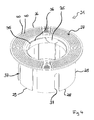
- Fig. 3
- in Darstellung gemäß
Fig. 1 den Unterputzsiphon mit abgenommener Abdeckplatte, - Fig. 4
- in perspektivischer Darstellung die Aufsatzmuffe in einem von der Abdeckplatte losgelösten Vormontagezustand, sowie
- Fig. 5
- in Darstellung gemäß
Fig.1 die Unterputzeinrichtung in einer zweiten Ausführungsform, bei der zusätzlich ein Verlängerungsadapter vorgesehen ist.
- Fig. 1
- 3 is a perspective view of a sanitary sub-luting device in a first embodiment, comprising a flush-mounted siphon, and a cladding element,
- Fig. 2
- in a perspective view of a cover plate and a top sleeve comprehensive cladding element,
- Fig. 3
- in illustration according to
Fig. 1 the flush-mounted siphon with removed cover plate, - Fig. 4
- in a perspective view of the attachment sleeve in a detached from the cover plate pre-assembly state, and
- Fig. 5
- in illustration according to
Fig.1 the Unterputzeinrichtung in a second embodiment, in which an extension adapter is additionally provided.
Einander entsprechende Teile sind in allen Figuren stets mit den gleichen Bezugszeichen versehen.Corresponding parts are always provided in all figures with the same reference numerals.
Der aus PE gefertigte Unterputzsiphon 2 umfasst im Wesentlichen ein Siphongehäuse 6, zulaufseitig einen Anschlussstutzen 7, sowie ablaufseitig ein Ablaufrohr 8. Im Siphongehäuse 6 ist ein hier nicht weiter erläuterter, zumindest im Betrieb des Unterputzsiphons 2 als Geruchsverschluss wirkender, Innenaufbau aufgenommen.The flush-mounted siphon 2 made of PE essentially comprises a siphon
Das Ablaufrohr 8 ist an einer Unterseite 9 des Siphongehäuses angeformt. Der Anschlussstutzen 7 ist an einer der Vorwand 5 zugewandten Frontseite 10 an das Siphongehäuse 6 angeformt. Der Anschlussstutzen 7 nimmt das Auslassrohr 4 unter Bildung einer dichtenden Verbindung auf.The
Die Begriffe "Unter-" und "Frontseite" sowie die korrespondierenden Begriffe "unten" und "vorne", sowie die sich hieraus ergebenden Entgegengesetzten Begriffe oben und hinten beziehen sich auf die bestimmungsgemäße Orientierung des Unterputzsiphons 2 und werden im Folgenden unabhängig von dessen tatsächlicher Stellung im umgebenden Raum verwendet. Insbesondere werden diese Begriffe ebenso für alle bestimmungsgemäß an dem Unterputzsiphon 2 angebrachten oder anzubringenden Bauteile herangezogen.The terms "bottom" and "front" and the corresponding terms "bottom" and "front", as well as the resulting opposite terms above and behind refer to the intended orientation of the flush-mounted siphon 2 and are used below regardless of its actual position in the surrounding space. In particular, these terms are also used for all intended as attached to the flush-mounted siphon 2 or components to be mounted.
Unterhalb des Anschlussstutzens 7 ist zu Reparatur- und/oder Reinigungszwecken eine mit einer Schraubkappe verschließbare Zugangsöffnung 11 in das Siphongehäuse 6 eingebracht. Um die Zugangsöffnung 11 zugänglich zu machen, ist in die Vorbauwand 5 eine Wandöffnung 12 eingebracht. Diese Wandöffnung 12 ist durch das Verkleidungselement 3 verdeckt.Below the connecting
In den
Das Verkleidungselement 3 ist im Wesentlichen durch eine rechteckige Abdeckplatte 20 aus Edelstahl, sowie eine Aufsatzmuffe 21 aus ABS gebildet.The
Die Abdeckplatte 20 ist derart dimensioniert, dass sie die Wandöffnung 12 überragt und somit verdecken kann. An ihrem Außenrand 22 ist die Abdeckplatte 20 insbesondere zur Vermeidung von scharfen Kanten sowohl an ihren Ecken abgerundet als auch quer zu ihrer Ebene zu einer - im Montagezustand bestimmungsgemäß der Vorbauwand 5 zugekehrten - Rückseite 23 hin umgebogen.The
Die Aufsatzmuffe 21 ist auf die Rückseite 23 der Abdeckplatte 20 aufgeklebt, wobei sie eine bezüglich ihrer Vertikalausdehnung exzentrisch in die Abdeckplatte 20 eingebrachte runde Durchführung 24 umrandet. Die Aufsatzmuffe 21 ist im Wesentlichen durch ein Rohrstück 25 gebildet, an dessen erstem flanschartigen Ende 26 eine Klebefläche 27 angeformt ist, die radial sowohl nach innen als auch nach außen das Rohrstück 25 überragt. An dieser Klebefläche 27 ist die Aufsatzmuffe 21 mit einem Silikonklebstoff auf die Abdeckplatte 20 aufgeklebt.The
Ausgehend von ihrem anderen Ende 28 sind in die Aufsatzmuffe 21 zwei axiale Montageschlitze 29 eingebracht.Starting from its
Aus
Da das Verkleidungselement 3 zum Einen zur Abdeckung der Wandöffnung 12 zum Anderen aber auch aus ästhetischen Gründen in seiner Längsausdehnung möglichst vertikal montiert werden soll, muss sichergestellt sein, dass die Aufsatzmuffe 21 bei der Montage des Verkleidungselements 3 derart auf der Abdeckplatte 20 verklebt wird, dass die Montageschlitze 29 in etwa auf der Längsachse der Abdeckplatte 20 angeordnet sind. Hierzu sind am Rand 33 der Durchführung 24 mehrere Ausbuchtungen der Abdeckplatte 20 unter Bildung von mehreren Zähnen 34 etwa rechtwinklig zur Rückseite 23 hin umgebogen. Im hier dargestellten Montagezustand des Verkleidungselements 3 greifen diese Zähne 34 in komplementäre Ausnehmungen 35 ein, die am Innenrand 36 der Aufsatzmuffe 21 eingebracht sind. Die Zähne 34 bzw. Ausnehmungen 35 sind dabei derart angeordnet, dass die Montageschlitze 29 an ihrer vorgesehenen Position liegen.Since the
Beide Montageschlitze 29 werden von jeweils zwei Federschlitzen 37 beidseitig flankiert. Diese Federschlitze 37 dienen eigentlich der Erhöhung der Flexibilität der Aufsatzmuffe 21. Jedoch kann das Verkleidungselement 3 bedarfsweise auch derart auf den Anschlussstutzen 7 aufgeschoben werden, dass Stege 30 in zwei gegenüberliegende Schlitze 37 eingreifen. Das Verkleidungselement 3 kann somit auch in zwei definierten Schrägstellungen an dem Unterputzsiphon befestigt werden.Both mounting
In
In
- 11
- UnterputzeinrichtungFlush device
- 22
- Unterputzsiphonrecess-
- 33
- Verkleidungselementcladding element
- 44
- Auslassrohroutlet pipe
- 55
- Vorbauwandstem wall
- 66
- Siphongehäusesiphon
- 77
- Anschlussstutzenspigot
- 88th
- Ablaufrohrdrain pipe
- 99
- Unterseitebottom
- 1010
- Frontseitefront
- 1111
- Zugangsöffnungaccess opening
- 1212
- Wandöffnungwall opening
- 2020
- Abdeckplattecover
- 2121
- Aufsatzmuffeattachment sleeve
- 2222
- Außenrandouter edge
- 2323
- Rückseiteback
- 2424
- Durchführungexecution
- 2525
- Rohrstückpipe section
- 2626
- EndeThe End
- 2727
- Klebeflächeadhesive surface
- 2828
- EndeThe End
- 2929
- Montageschlitzmounting slot
- 3030
- Stegweb
- 3131
- Radialteilradial part
- 3232
- Tangentialteiltangential part
- 3333
- Randedge
- 3434
- Zahntooth
- 3535
- Ausnehmungrecess
- 3636
- Innenrandinner edge
- 3737
- Federschlitzspring slot
- 4040
- Rillegroove
- 5050
- VerlängerungsadapterVerlängerungsadapter
- 5151
- Rohrstückpipe section
- 5252
- EndeThe End
- 5353
- EndeThe End
- 5454
- Montageschlitzmounting slot
Claims (10)
Applications Claiming Priority (1)
| Application Number | Priority Date | Filing Date | Title |
|---|---|---|---|
| DE201020001240 DE202010001240U1 (en) | 2010-01-21 | 2010-01-21 | Sanitary sub-plasters with associated cladding element |
Publications (3)
| Publication Number | Publication Date |
|---|---|
| EP2354335A1 true EP2354335A1 (en) | 2011-08-10 |
| EP2354335B1 EP2354335B1 (en) | 2014-12-24 |
| EP2354335B8 EP2354335B8 (en) | 2015-03-11 |
Family
ID=42194522
Family Applications (1)
| Application Number | Title | Priority Date | Filing Date |
|---|---|---|---|
| EP20110000426 Active EP2354335B8 (en) | 2010-01-21 | 2011-01-20 | Sanitary flush-mounted attachment with associated cladding element |
Country Status (2)
| Country | Link |
|---|---|
| EP (1) | EP2354335B8 (en) |
| DE (1) | DE202010001240U1 (en) |
Families Citing this family (1)
| Publication number | Priority date | Publication date | Assignee | Title |
|---|---|---|---|---|
| DE202020100660U1 (en) * | 2020-02-07 | 2020-03-02 | Angela Haas | Concealed siphon |
Citations (3)
| Publication number | Priority date | Publication date | Assignee | Title |
|---|---|---|---|---|
| DE3447098C1 (en) * | 1984-12-22 | 1986-03-20 | Helmuth Dallmer oHG, 5760 Arnsberg | Flush-mounted siphon |
| WO1996015330A1 (en) * | 1994-11-15 | 1996-05-23 | Hutterer & Lechner Kommanditgesellschaft | Concealed siphon |
| DE202004013127U1 (en) * | 2004-08-20 | 2006-01-05 | Viega Gmbh & Co. Kg | Odor trap for a drain |
-
2010
- 2010-01-21 DE DE201020001240 patent/DE202010001240U1/en not_active Expired - Lifetime
-
2011
- 2011-01-20 EP EP20110000426 patent/EP2354335B8/en active Active
Patent Citations (3)
| Publication number | Priority date | Publication date | Assignee | Title |
|---|---|---|---|---|
| DE3447098C1 (en) * | 1984-12-22 | 1986-03-20 | Helmuth Dallmer oHG, 5760 Arnsberg | Flush-mounted siphon |
| WO1996015330A1 (en) * | 1994-11-15 | 1996-05-23 | Hutterer & Lechner Kommanditgesellschaft | Concealed siphon |
| DE202004013127U1 (en) * | 2004-08-20 | 2006-01-05 | Viega Gmbh & Co. Kg | Odor trap for a drain |
Also Published As
| Publication number | Publication date |
|---|---|
| EP2354335B8 (en) | 2015-03-11 |
| EP2354335B1 (en) | 2014-12-24 |
| DE202010001240U1 (en) | 2010-05-20 |
Similar Documents
| Publication | Publication Date | Title |
|---|---|---|
| EP3012377B1 (en) | Spray nozzle | |
| EP1382757A1 (en) | Sanitary installation unit | |
| DE202010009280U1 (en) | Fastening device for fastening a wall-mounted sanitary object | |
| CH715798B1 (en) | Fitting arrangement. | |
| DE202009004938U1 (en) | mounting kit | |
| EP2778298B1 (en) | Sanitary fitting connection system | |
| EP3064663B1 (en) | Sanitary device | |
| DE4443005A1 (en) | Air hose and connection nozzle combination | |
| EP2354335B1 (en) | Sanitary flush-mounted attachment with associated cladding element | |
| EP2876222B1 (en) | Unit comprising a fastening device for a wall-mounted toilet and a holding element. | |
| EP2184411B1 (en) | Connection box to assemble sanitary fittings | |
| EP2700760A1 (en) | Shower WC with removable shower arm | |
| EP1607670A1 (en) | Connection device for a flexible tube | |
| DE20321431U1 (en) | Bathroom fitting, for mounting under the plaster, has an interrupted threading at the box for a ring flange to be screwed down into the correct position at a gap from the leading edge of the box | |
| EP3321430A1 (en) | Fixing of a covering plate of an inspection aperture | |
| DE102011013349A1 (en) | Discharge device e.g. floor drain for waste water used in e.g. bathroom, has sealing unit that is in contact with the drain port of trap | |
| EP2226540B1 (en) | Sanitary built-in fitting | |
| EP2101001A2 (en) | Built in box with hose-lead connections for a sanitary fitting | |
| DE102006057206B4 (en) | Sanitary water valve provided with a steel regulator | |
| EP3146115B1 (en) | Faucet extension for connecting a water pipe to a fitting | |
| DE19634149C2 (en) | Tubular siphon with plug connection | |
| DE4134069C1 (en) | Siphon connection on wash basin - joins to lead a drainage pipe leading through wall and includes flexible pipe insert | |
| WO2010100210A2 (en) | Adapter system for connecting water-carrying surface-mounted fittings | |
| DE102005041258A1 (en) | Steamer, has dosing pipe arranged inside steamer chamber and includes opening attached to evaporation equipment, in which junction between pipe and fresh water supply pipeline is outside chamber | |
| EP0819797A1 (en) | Armature with drains |
Legal Events
| Date | Code | Title | Description |
|---|---|---|---|
| PUAI | Public reference made under article 153(3) epc to a published international application that has entered the european phase |
Free format text: ORIGINAL CODE: 0009012 |
|
| AK | Designated contracting states |
Kind code of ref document: A1 Designated state(s): AL AT BE BG CH CY CZ DE DK EE ES FI FR GB GR HR HU IE IS IT LI LT LU LV MC MK MT NL NO PL PT RO RS SE SI SK SM TR |
|
| AX | Request for extension of the european patent |
Extension state: BA ME |
|
| 17P | Request for examination filed |
Effective date: 20120125 |
|
| RIC1 | Information provided on ipc code assigned before grant |
Ipc: E03C 1/28 20060101AFI20120813BHEP |
|
| 17Q | First examination report despatched |
Effective date: 20120917 |
|
| GRAP | Despatch of communication of intention to grant a patent |
Free format text: ORIGINAL CODE: EPIDOSNIGR1 |
|
| INTG | Intention to grant announced |
Effective date: 20140912 |
|
| GRAS | Grant fee paid |
Free format text: ORIGINAL CODE: EPIDOSNIGR3 |
|
| GRAA | (expected) grant |
Free format text: ORIGINAL CODE: 0009210 |
|
| AK | Designated contracting states |
Kind code of ref document: B1 Designated state(s): AL AT BE BG CH CY CZ DE DK EE ES FI FR GB GR HR HU IE IS IT LI LT LU LV MC MK MT NL NO PL PT RO RS SE SI SK SM TR |
|
| REG | Reference to a national code |
Ref country code: GB Ref legal event code: FG4D Free format text: NOT ENGLISH |
|
| REG | Reference to a national code |
Ref country code: CH Ref legal event code: EP |
|
| REG | Reference to a national code |
Ref country code: IE Ref legal event code: FG4D Free format text: LANGUAGE OF EP DOCUMENT: GERMAN |
|
| REG | Reference to a national code |
Ref country code: AT Ref legal event code: REF Ref document number: 703222 Country of ref document: AT Kind code of ref document: T Effective date: 20150115 |
|
| REG | Reference to a national code |
Ref country code: DE Ref legal event code: R096 Ref document number: 502011005362 Country of ref document: DE Effective date: 20150212 |
|
| RAP2 | Party data changed (patent owner data changed or rights of a patent transferred) |
Owner name: HAAS, ANGELA |
|
| RIN2 | Information on inventor provided after grant (corrected) |
Inventor name: THOMAS HAAS |
|
| REG | Reference to a national code |
Ref country code: DE Ref legal event code: R081 Ref document number: 502011005362 Country of ref document: DE Owner name: HAAS, ANGELA, DE Free format text: FORMER OWNER: HAAS, THOMAS, 91074 HERZOGENAURACH, DE Effective date: 20150213 |
|
| REG | Reference to a national code |
Ref country code: NL Ref legal event code: VDEP Effective date: 20141224 |
|
| PG25 | Lapsed in a contracting state [announced via postgrant information from national office to epo] |
Ref country code: LT Free format text: LAPSE BECAUSE OF FAILURE TO SUBMIT A TRANSLATION OF THE DESCRIPTION OR TO PAY THE FEE WITHIN THE PRESCRIBED TIME-LIMIT Effective date: 20141224 Ref country code: FI Free format text: LAPSE BECAUSE OF FAILURE TO SUBMIT A TRANSLATION OF THE DESCRIPTION OR TO PAY THE FEE WITHIN THE PRESCRIBED TIME-LIMIT Effective date: 20141224 Ref country code: NO Free format text: LAPSE BECAUSE OF FAILURE TO SUBMIT A TRANSLATION OF THE DESCRIPTION OR TO PAY THE FEE WITHIN THE PRESCRIBED TIME-LIMIT Effective date: 20150324 |
|
| REG | Reference to a national code |
Ref country code: LT Ref legal event code: MG4D |
|
| PG25 | Lapsed in a contracting state [announced via postgrant information from national office to epo] |
Ref country code: GR Free format text: LAPSE BECAUSE OF FAILURE TO SUBMIT A TRANSLATION OF THE DESCRIPTION OR TO PAY THE FEE WITHIN THE PRESCRIBED TIME-LIMIT Effective date: 20150325 Ref country code: SE Free format text: LAPSE BECAUSE OF FAILURE TO SUBMIT A TRANSLATION OF THE DESCRIPTION OR TO PAY THE FEE WITHIN THE PRESCRIBED TIME-LIMIT Effective date: 20141224 Ref country code: RS Free format text: LAPSE BECAUSE OF FAILURE TO SUBMIT A TRANSLATION OF THE DESCRIPTION OR TO PAY THE FEE WITHIN THE PRESCRIBED TIME-LIMIT Effective date: 20141224 Ref country code: LV Free format text: LAPSE BECAUSE OF FAILURE TO SUBMIT A TRANSLATION OF THE DESCRIPTION OR TO PAY THE FEE WITHIN THE PRESCRIBED TIME-LIMIT Effective date: 20141224 Ref country code: HR Free format text: LAPSE BECAUSE OF FAILURE TO SUBMIT A TRANSLATION OF THE DESCRIPTION OR TO PAY THE FEE WITHIN THE PRESCRIBED TIME-LIMIT Effective date: 20141224 |
|
| PG25 | Lapsed in a contracting state [announced via postgrant information from national office to epo] |
Ref country code: NL Free format text: LAPSE BECAUSE OF FAILURE TO SUBMIT A TRANSLATION OF THE DESCRIPTION OR TO PAY THE FEE WITHIN THE PRESCRIBED TIME-LIMIT Effective date: 20141224 |
|
| PG25 | Lapsed in a contracting state [announced via postgrant information from national office to epo] |
Ref country code: SK Free format text: LAPSE BECAUSE OF FAILURE TO SUBMIT A TRANSLATION OF THE DESCRIPTION OR TO PAY THE FEE WITHIN THE PRESCRIBED TIME-LIMIT Effective date: 20141224 Ref country code: CZ Free format text: LAPSE BECAUSE OF FAILURE TO SUBMIT A TRANSLATION OF THE DESCRIPTION OR TO PAY THE FEE WITHIN THE PRESCRIBED TIME-LIMIT Effective date: 20141224 Ref country code: RO Free format text: LAPSE BECAUSE OF FAILURE TO SUBMIT A TRANSLATION OF THE DESCRIPTION OR TO PAY THE FEE WITHIN THE PRESCRIBED TIME-LIMIT Effective date: 20141224 Ref country code: EE Free format text: LAPSE BECAUSE OF FAILURE TO SUBMIT A TRANSLATION OF THE DESCRIPTION OR TO PAY THE FEE WITHIN THE PRESCRIBED TIME-LIMIT Effective date: 20141224 Ref country code: ES Free format text: LAPSE BECAUSE OF FAILURE TO SUBMIT A TRANSLATION OF THE DESCRIPTION OR TO PAY THE FEE WITHIN THE PRESCRIBED TIME-LIMIT Effective date: 20141224 |
|
| REG | Reference to a national code |
Ref country code: CH Ref legal event code: PL |
|
| PG25 | Lapsed in a contracting state [announced via postgrant information from national office to epo] |
Ref country code: PL Free format text: LAPSE BECAUSE OF FAILURE TO SUBMIT A TRANSLATION OF THE DESCRIPTION OR TO PAY THE FEE WITHIN THE PRESCRIBED TIME-LIMIT Effective date: 20141224 Ref country code: LU Free format text: LAPSE BECAUSE OF FAILURE TO SUBMIT A TRANSLATION OF THE DESCRIPTION OR TO PAY THE FEE WITHIN THE PRESCRIBED TIME-LIMIT Effective date: 20150120 Ref country code: IS Free format text: LAPSE BECAUSE OF FAILURE TO SUBMIT A TRANSLATION OF THE DESCRIPTION OR TO PAY THE FEE WITHIN THE PRESCRIBED TIME-LIMIT Effective date: 20150424 |
|
| REG | Reference to a national code |
Ref country code: DE Ref legal event code: R097 Ref document number: 502011005362 Country of ref document: DE |
|
| PG25 | Lapsed in a contracting state [announced via postgrant information from national office to epo] |
Ref country code: MC Free format text: LAPSE BECAUSE OF FAILURE TO SUBMIT A TRANSLATION OF THE DESCRIPTION OR TO PAY THE FEE WITHIN THE PRESCRIBED TIME-LIMIT Effective date: 20141224 |
|
| PG25 | Lapsed in a contracting state [announced via postgrant information from national office to epo] |
Ref country code: LI Free format text: LAPSE BECAUSE OF NON-PAYMENT OF DUE FEES Effective date: 20150131 Ref country code: DK Free format text: LAPSE BECAUSE OF FAILURE TO SUBMIT A TRANSLATION OF THE DESCRIPTION OR TO PAY THE FEE WITHIN THE PRESCRIBED TIME-LIMIT Effective date: 20141224 Ref country code: CH Free format text: LAPSE BECAUSE OF NON-PAYMENT OF DUE FEES Effective date: 20150131 |
|
| REG | Reference to a national code |
Ref country code: FR Ref legal event code: ST Effective date: 20150930 |
|
| PLBE | No opposition filed within time limit |
Free format text: ORIGINAL CODE: 0009261 |
|
| REG | Reference to a national code |
Ref country code: IE Ref legal event code: MM4A |
|
| STAA | Information on the status of an ep patent application or granted ep patent |
Free format text: STATUS: NO OPPOSITION FILED WITHIN TIME LIMIT |
|
| GBPC | Gb: european patent ceased through non-payment of renewal fee |
Effective date: 20150324 |
|
| PG25 | Lapsed in a contracting state [announced via postgrant information from national office to epo] |
Ref country code: FR Free format text: LAPSE BECAUSE OF NON-PAYMENT OF DUE FEES Effective date: 20150224 |
|
| 26N | No opposition filed |
Effective date: 20150925 |
|
| PG25 | Lapsed in a contracting state [announced via postgrant information from national office to epo] |
Ref country code: IT Free format text: LAPSE BECAUSE OF FAILURE TO SUBMIT A TRANSLATION OF THE DESCRIPTION OR TO PAY THE FEE WITHIN THE PRESCRIBED TIME-LIMIT Effective date: 20141224 |
|
| PG25 | Lapsed in a contracting state [announced via postgrant information from national office to epo] |
Ref country code: IE Free format text: LAPSE BECAUSE OF NON-PAYMENT OF DUE FEES Effective date: 20150120 Ref country code: GB Free format text: LAPSE BECAUSE OF NON-PAYMENT OF DUE FEES Effective date: 20150324 |
|
| PG25 | Lapsed in a contracting state [announced via postgrant information from national office to epo] |
Ref country code: SI Free format text: LAPSE BECAUSE OF FAILURE TO SUBMIT A TRANSLATION OF THE DESCRIPTION OR TO PAY THE FEE WITHIN THE PRESCRIBED TIME-LIMIT Effective date: 20141224 |
|
| PG25 | Lapsed in a contracting state [announced via postgrant information from national office to epo] |
Ref country code: MT Free format text: LAPSE BECAUSE OF FAILURE TO SUBMIT A TRANSLATION OF THE DESCRIPTION OR TO PAY THE FEE WITHIN THE PRESCRIBED TIME-LIMIT Effective date: 20141224 |
|
| PG25 | Lapsed in a contracting state [announced via postgrant information from national office to epo] |
Ref country code: HU Free format text: LAPSE BECAUSE OF FAILURE TO SUBMIT A TRANSLATION OF THE DESCRIPTION OR TO PAY THE FEE WITHIN THE PRESCRIBED TIME-LIMIT; INVALID AB INITIO Effective date: 20110120 Ref country code: SM Free format text: LAPSE BECAUSE OF FAILURE TO SUBMIT A TRANSLATION OF THE DESCRIPTION OR TO PAY THE FEE WITHIN THE PRESCRIBED TIME-LIMIT Effective date: 20141224 Ref country code: BG Free format text: LAPSE BECAUSE OF FAILURE TO SUBMIT A TRANSLATION OF THE DESCRIPTION OR TO PAY THE FEE WITHIN THE PRESCRIBED TIME-LIMIT Effective date: 20141224 |
|
| PGFP | Annual fee paid to national office [announced via postgrant information from national office to epo] |
Ref country code: BE Payment date: 20170124 Year of fee payment: 7 |
|
| PG25 | Lapsed in a contracting state [announced via postgrant information from national office to epo] |
Ref country code: CY Free format text: LAPSE BECAUSE OF FAILURE TO SUBMIT A TRANSLATION OF THE DESCRIPTION OR TO PAY THE FEE WITHIN THE PRESCRIBED TIME-LIMIT Effective date: 20141224 |
|
| PG25 | Lapsed in a contracting state [announced via postgrant information from national office to epo] |
Ref country code: PT Free format text: LAPSE BECAUSE OF FAILURE TO SUBMIT A TRANSLATION OF THE DESCRIPTION OR TO PAY THE FEE WITHIN THE PRESCRIBED TIME-LIMIT Effective date: 20150424 |
|
| PG25 | Lapsed in a contracting state [announced via postgrant information from national office to epo] |
Ref country code: TR Free format text: LAPSE BECAUSE OF FAILURE TO SUBMIT A TRANSLATION OF THE DESCRIPTION OR TO PAY THE FEE WITHIN THE PRESCRIBED TIME-LIMIT Effective date: 20141224 |
|
| PG25 | Lapsed in a contracting state [announced via postgrant information from national office to epo] |
Ref country code: MK Free format text: LAPSE BECAUSE OF FAILURE TO SUBMIT A TRANSLATION OF THE DESCRIPTION OR TO PAY THE FEE WITHIN THE PRESCRIBED TIME-LIMIT Effective date: 20141224 |
|
| PG25 | Lapsed in a contracting state [announced via postgrant information from national office to epo] |
Ref country code: AL Free format text: LAPSE BECAUSE OF FAILURE TO SUBMIT A TRANSLATION OF THE DESCRIPTION OR TO PAY THE FEE WITHIN THE PRESCRIBED TIME-LIMIT Effective date: 20141224 |
|
| REG | Reference to a national code |
Ref country code: BE Ref legal event code: MM Effective date: 20180131 |
|
| PG25 | Lapsed in a contracting state [announced via postgrant information from national office to epo] |
Ref country code: BE Free format text: LAPSE BECAUSE OF NON-PAYMENT OF DUE FEES Effective date: 20180131 |
|
| PGFP | Annual fee paid to national office [announced via postgrant information from national office to epo] |
Ref country code: AT Payment date: 20230118 Year of fee payment: 13 |
|
| PGFP | Annual fee paid to national office [announced via postgrant information from national office to epo] |
Ref country code: AT Payment date: 20240118 Year of fee payment: 14 |
|
| PGFP | Annual fee paid to national office [announced via postgrant information from national office to epo] |
Ref country code: DE Payment date: 20240228 Year of fee payment: 14 |