EP2352004B1 - Überwachungssystem für eine Brennstoffspeicheranlage - Google Patents
Überwachungssystem für eine Brennstoffspeicheranlage Download PDFInfo
- Publication number
- EP2352004B1 EP2352004B1 EP11151197.8A EP11151197A EP2352004B1 EP 2352004 B1 EP2352004 B1 EP 2352004B1 EP 11151197 A EP11151197 A EP 11151197A EP 2352004 B1 EP2352004 B1 EP 2352004B1
- Authority
- EP
- European Patent Office
- Prior art keywords
- inspection
- storage
- fumes
- conductive
- resists
- Prior art date
- Legal status (The legal status is an assumption and is not a legal conclusion. Google has not performed a legal analysis and makes no representation as to the accuracy of the status listed.)
- Not-in-force
Links
Images

Classifications
-
- G—PHYSICS
- G01—MEASURING; TESTING
- G01M—TESTING STATIC OR DYNAMIC BALANCE OF MACHINES OR STRUCTURES; TESTING OF STRUCTURES OR APPARATUS, NOT OTHERWISE PROVIDED FOR
- G01M3/00—Investigating fluid-tightness of structures
- G01M3/02—Investigating fluid-tightness of structures by using fluid or vacuum
- G01M3/26—Investigating fluid-tightness of structures by using fluid or vacuum by measuring rate of loss or gain of fluid, e.g. by pressure-responsive devices, by flow detectors
- G01M3/32—Investigating fluid-tightness of structures by using fluid or vacuum by measuring rate of loss or gain of fluid, e.g. by pressure-responsive devices, by flow detectors for containers, e.g. radiators
Definitions
- the invention relates to a monitoring system for a fuel storage system according to the preamble of claim 1.
- the above systems although advanced and mature, do not describe any safety devices in the development of the systems or the interconnections between the explosive and the non-explosive areas, because even if the safety device is housed in the inspection well, ie in the explosive area, the monitoring, Control and power supply of the equipment usually from the outside.
- the required connections usually require piping through which toxic and explosive vapors of stored, explosive and unhealthy media or leaked media remnants can get outside of the inspection shaft and elsewhere create a potentially explosive or unhealthy environment can. This again forms a source of danger for the maintenance and service personnel.
- the objects of the present invention are to describe such a safety device.
- the present invention therefore provides for the implementation of a monitoring system positioned in the memory chamber of the accumulator and therefore in the ATEX Zone 1 area, preventing vapors from escaping out of the shaft via the connecting pipes of the terminals of the monitoring unit.
- the advantage is the generally higher safety of petrol station and maintenance personnel and in reducing the cost of materials of the external leak detector or this leak detector containing cabinet, in which now no facilities to protect against explosive or toxic vapors are provided.
- the monitoring systems of at least two memories can be designed such that the individual monitoring systems outside the control shafts are centrally located in one Monitoring cabinet are combined, which also allows a simpler and faster maintenance of the monitoring systems.
- the advantage of this exemplary monitoring system is the merging of the monitoring units of the individual memories within a cabinet outside the control shafts, which obviates the need for access to the various shafts, and thus to the danger area of the various memories. If a maintenance or service work is carried out, extensive cleaning work must be carried out in advance to remove the toxic and explosive vapors of the stored media or leaked media residues themselves (eg due to improper handling during filling or level measurement with shaft dipsticks). This extraordinary cleaning costs additional time and money. It is now advantageous that the maintenance can be carried out without access to the inspection shaft and that this represents a considerable saving in the troublesome safety procedure for the cleaning and ventilation of the manhole, which are necessary before the operator has access to this area. In addition, there are considerably fewer potential risks and therefore lower safety requirements. Maintenance is also carried out in an ergonomically favorable position, which also reduces the risk of injury.
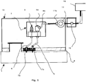
- the shielded cable usually passes through an intermediate shaft 12 in order then to reach the leak detector or the cabinet 19 containing the leak detector.
- FIG. 1 A preferred scheme of the system is provided with a central control and monitoring cabinet for multiple memories.
- the connection of the gap of the memory with the centralized monitoring cabinet unit 13 via the Suction and measuring line made of copper, steel, conductive PVC or other material which resists the stored and conductive product 4 (4a, 4b, 4c) and 5 (5a, 5b, 5c).
- the exit points from the inspection shaft should be sealed to prevent the escape of vapors.
- At least one second memory is connected to the centralized monitoring cabinet unit 13.
- the centralized monitor unit has a separate sector for each memory.
- a single collector comprising a static pressure / vacuum control system (suction line) 15a, 15b, 15c of a static pressure / vacuum measuring sensor 16a, 16b, 16c and in a preferred version a manometer (17a 17b, 17c each for each memory
- the shielded power cables 18a, 18b, 18c of the pressure / vacuum measuring sensors 16a, 16b, 16c lead to the leak detector.
Landscapes
- Physics & Mathematics (AREA)
- General Physics & Mathematics (AREA)
- Examining Or Testing Airtightness (AREA)
- Electrical Control Of Air Or Fuel Supplied To Internal-Combustion Engine (AREA)
Description
- Die Erfindung bezieht sich auf ein Überwachungssystem für eine Brennstoffspeicheranlage gemäß dem Oberbegriff des Anspruchs 1.
- Aus der
US 2004 261503 A1 ist eine Leckwarnanlage für die Lagerung von explosions-und gesundheitsgefährdende Brennstoffe in Brennstoffspeicheranlagen bekannt. Dabei werden die Sensoren und das Vakuumpumpensystem zur Überwachung des Zwischenraums im Kontrollschacht (im explosionsgefährdeten Bereich ATEX - atmospheres et explosibles - Zone 1) eines erdvergrabenen Tanks platziert. Die Wartung und der Austausch dieser Lecküberwachungsanlage ist demnach besonders zeitaufwendig, kostenintensiv und birgt zudem ein gewisses Sicherheitsrisiko durch das Arbeiten im explosionsgefährdeten Bereich für das Wartungspersonal. Das Wartungspersonal muss für diese Gefahrenzone speziell ausgebildet sein sowie die Sicherheitsvorschriften genau befolgen, was zusätzlichen Kontroll- und Schulungsaufwand beinhaltet. Außerdem müssen alle Wartungs- und Servicearbeiten in dieser Zone immer von mindestens zwei qualifizierten Arbeitern durchgeführt werden, damit der zweite bei Gasaustritt den ersten Arbeiter aus der Gefahrenzone heraus bringen kann, wenn dieser nicht bewegungsfähig bzw. ohnmächtig wird. Ein zweiter Nachteil ergibt sich aus den hohen Materialkosten, da alle verbauten Elemente für die entsprechende explosionsgefährliche Zone gebaut und geprüft sein müssen, was diese sehr teuer macht. - Aus dem Patent
US 5,052,217 ist eine weitere Überwachungseinheit einer Brennstoffspeicheranlage bekannt. Diese umfasst gleichfalls einen Leckmelder (mit der Nummer 74 im Text angegeben), der ebenso in der Gefahrenzone im Kontrollschacht angebracht ist und deshalb die selben Nachteile in Bezug auf Wartung aufweist, wie bereits beiUS 2004 261503 beschrieben. - Im Patent
US 2004 4 234338 A1 wird eine Leckwarnanlage für Brennstoffspeicheranlagen erläutert, in der die elektrischen Leitungen aus der Gefahrenzone herausgeführt werden. Die zur Überwachung eingesetzten Sensoren bleiben allerdings, wie in den beiden vorherigen Veröffentlichungen beschrieben, in der Gefahrenzone der Tanköffnung. - Aus der Veröffentlichung
WO 2009 13 2365 ist eine Leckwarnanlage für doppelwandige Fluidleitungen, insbesondere für Tankstellen bekannt, bestehend aus: - einer statischen Druck- /Unterdrucküberwachungsleitung,
- einer Leitung und
- einem Verbindungssystem der Leitungen mit dem Zwischenraum des Speichers
- ein Ventil und
- eine Regelvorrichtung.
- Ferner ist aus der Schrift
GB 2 418 952 A - Die obigen Systeme, auch wenn fortgeschritten und ausgereift, beschreiben keinerlei Sicherheitseinrichtungen bei der Entwicklung der Systeme oder den Verbindungsleitungen zwischen dem explosionsgefährlichen und dem nicht-explosionsgefährlichen Bereich, denn auch wenn die Sicherheitseinrichtung im Kontrollschacht, also im explosionsgefährlichen Bereich untergebracht ist, erfolgt die Überwachung, Steuerung und Stromversorgung der Einrichtungen in der Regel von außen. Die dafür benötigten Anschlüsse bedürfen in der Regel Rohrleitungen, durch die giftige und explosive Dämpfe der gelagerten, explosions- und gesundheitsgefährlichen Medien oder ausgetretenen Medienreste außerhalb des Kontrollschachtes gelangen können und woanders wiederum eine explosions- oder gesundheitsgefährliche Umgebung erzeugen können. Dies bildet wiederum eine Gefahrenquelle für das Wartungs- und Servicepersonal. Die Aufgaben der vorliegenden Erfindung liegen darin, eine solche Sicherheitseinrichtung zu beschreiben.
- Weiterführend verursachen die obigen Systeme aufgrund des explosionsgefährdeten Bereichs ATEX Zone 1, wie bereits eingangs erläutert, große Kosten für die Herstellung der zu verwendenden Materialien mit den notwendigen Eigenschaften (Explosionssicherheit, die speziell zertifiziert werden muss) und setzen dazu das Wartungs- oder Servicepersonal aufgrund des Arbeitens in der explosionsgefährdeten Umgebung einer prinzipiellen Arbeitsgefahr aus, der nur mit aufwändigen Vorgangs- und Arbeitssicherheitsanweisen, teuren Schulungen und speziellen Arbeitsutensilien begegnet werden kann. Eine regelmäßige Wartung der Sicherheitseinrichtungen im Gefahrenbereich (hier des Kontrollschachtes einer Brennstoffspeicheranlage) ist gesetzliche Pflicht.
- Um diese Kosten generell zu verringern wird zudem in der vorliegenden Erfindung als fortführende Stufe aufgezeigt, dass durch die Auslagerung der Überwachungseinheit aus dem Kontrollschacht die Wartung und Säuberung von Kontrollschächten bekannter Brennstoffspeicheranlagen noch gefahrenreduzierter und ökonomisch noch effizienter gestaltet werden können, indem die Arbeiten nun außerhalb des explosionsgefährdeten Bereiches erfolgen können.
- Die Anordnungen der vorliegenden Erfindung werden gemäß dem kennzeichnenden Teil des Anspruchs 1 gelöst.
- Die vorliegende Erfindung sieht daher vor, ein Überwachungssystem auszuführen, das im Kontrollschacht des Speichers und daher im Bereich ATEX Zone 1 positioniert ist, wobei verhindert wird, dass Dämpfe aus dem Schacht über die Verbindungsrohrleitungen der Anschlüsse der Überwachungseinheit nach außen gelangen.
- Der Vorteil besteht in der allgemein höheren Sicherheit des Tankstellen- und Wartungspersonals sowie im Herabsetzen der Materialkosten des äußeren Leckmelders oder des diesen Leckmelder enthaltenden Schrankes, bei dem nun keinerlei Einrichtungen zum Schutz vor explosiven oder giftigen Dämpfen mehr vorzusehen sind. Beispielsweise können die Überwachungssysteme mindestens zweier Speicher derart ausgeführt werden, dass die einzelnen Überwachungssysteme außerhalb der Kontrollschächte zentral in einem Überwachungsschrank zusammengeführt werden, was zudem noch eine einfachere und raschere Wartung der Überwachungssysteme erlaubt.
- Zusammengefasst besteht der Vorteil dieses beispielhaften Überwachungssystems in der Zusammenführung der Überwachungseinheiten der einzelnen Speicher innerhalb eines Schrankes außerhalb der Kontrollschächte, was den Zugang zu den verschiedenen Schächten, und damit zu dem Gefahrenbereich der verschiedenen Speicher überflüssig macht. Denn wird eine Wartung- oder Servicearbeit ausgeführt, müssen im Vorhinein umfangreiche Reinigungsarbeiten zur Entfernung der giftigen und explosiven Dämpfe der gelagerten Medien oder ausgetretenen Medienresten selbst (z. B. durch den unsachgemäßen Umgang bei der Befüllung oder Füllstandsmessung mit Peilstäben des Schachtes) abgewickelt werden. Diese außerordentliche Reinigung kostet zusätzlich Zeit und Geld. Vorteilhaft ist nun, dass die Wartung ohne Zugang zum Kontrollschacht ausgeführt werden kann und dass dies ein erhebliches Ersparnis beim mühsamen Sicherheitsvorgehen für die Säuberung und Lüftung des Mannloches bedeutet, die vor dem Zugang der Bedienungsperson zu diesem Bereich notwendig sind. Zudem bestehen nun wesentlich weniger Gefahrenpotenziale und damit auch geringere Sicherheitsanforderungen. Die Wartung wird zudem in einer ergonomisch günstigen Position ausgeführt, was zudem die Verletzungsgefahr reduziert.
- Überdies ist nicht mehr die Anwesenheit einer zweiten Bedienungsperson für die Sicherheitsmaßnahmen notwendig, die im Notfall überwacht und eingreift, um den Austritt der ersten Bedienungsperson aus dem Schacht oder dem Mannloch zu begleiten.
- Als Endbetrachtung ist hinzuzufügen, dass neben den beschriebenen Vorteilen zudem eine erhebliche Zeitersparnis bei den Überwachungs-und Wartungsarbeiten erzielt wird. Verbunden ist diese mit einer Herabsetzung der Materialkosten der verschiedenen Bestandteile des äußeren Kontrollschrankes, denn die Bestandteile der Sicherheitseinrichtungen befinden sich nicht mehr in der ATEX Gefahrenzone 1, also im Kontrollschacht, sondern in der ATEX Gefahrenzone 2, bei der wesentlich geringe Schutzauflagen eingehalten werden müssen.
- Die Sicherheitseinrichtungen eines Überwachungssystems für eine Brennstoffspeicheranlage sehen gemäß der Erfindung vor:
- einen doppelwandigen Speicher, der einen Kontrollschacht besitzt,
- eine Kontroll- und Überwachungseinheit für den Speicher, die im Kontrollschacht angeordnet und mit dem Zwischenraum der Doppelwand des Speichers mittels einer Rohrleitung verbunden ist - aus Kupfer, Stahl oder leitfähigem PVC oder einem anderen Material, das den Dämpfen des gelagerten Mediums widersteht - zur Messung des Druckes und eine Rohrleitung zur Absaugung - aus Kupfer Stahl oder leitfähigem PVC oder einem anderen Material, das den Dämpfen des gelagerten Mediums widersteht und leitfähig ist -,
- die Kontrolleinheit umfasst eine Fluidsammelleitung als Ansaugrohrleitung und eine Messleitung mit einem Druckmesssensor für den Zwischenraum der Doppelwand in einer bevorzugten Version auch mit einem Manometer,
- der Druckmesssensor ist mit dem äußeren Leckmelder verbunden,
- die Verbindung wischen der Kontrolleinheit und dem Leckmelder erfolgt mittels Leitungen, die in Rohrleitungen aus beliebigen Materialien verlaufen. Diese müssen versiegelt werden, um das Austreten der Dämpfe im Kontrollschacht über die Anschlussrohrleitung zu vermeiden und eine größere Gesamtsicherheit zu gewährleisten.
- Merkmale und Einzelheiten gehen aus den Ansprüchen und aus der folgenden Beschreibung eines bevorzugten Beispiels hervor. In der Zeichnung zeigen:
-
Figur 1 eine schematische Ansicht eines Überwachungssystems für einen Speicher mit der Sicherheitsverbindung, die das Aufsteigen der Dämpfe zu Leckmelder 19 vermeidet. Das System umfasst gemäß der Erfindung einen doppelwandigen Speicher 1 und seinen Kontrollschacht 10. Die Kontrolleinheit 3 ist mit der Doppelwand 6 über zwei Rohrleitungen (der Mess- und der Saugleitung) aus Kupfer, Stahl, leitfähigem PVC oder einem anderen Material, das dem gelagerten und leitfähigen Produkt 4, 5 widersteht, verbunden. Um eine sichere und einfache Verbindung zwischen den Rohrleitungen 4, 5 und dem Zwischenraum des Speichers 6 sicherzustellen, ist eine Verbindungsbolzen 7a, 7b zwischengeschaltet. Die Kontrolleinheit umfasst ein statisches Druck-/Unterdruck-Reguliersystem 8 (Saugleitung), einen statischen Druck-/Unterdruck-Messsensor 9a (Messleitung) und optional ein Manometer. Die Kontrolleinheit 3 ist mittels eines abgeschirmten Stromkabels mit innerer Sicherheit 9b mit einem Klemmkörper 11 verbunden. Die Durchführung erfolgt innerhalb eines Schutzschlauchs um eine Beschädigung des abgeschirmten Stromkabels durch Wartungs- und Reinigungsarbeiten im Kontrollschacht zu verhindern. Das Klemmgehäuse wird mit einem geeigneten Harz gefüllt, das dem im Speicher gelagerten Produkt widersteht. Das mit Harz gefüllte Klemmgehäuse verhindert den Übertritt von Dämpfen in die Anschlussrohrleitung. Der Austritt des geschirmten Stromkabels aus dem Klemmgehäuse erfolgt über eine Kabelklemme ATEX 11b, um auch dadurch den Dampfdurchtritt in das Rohr zu vermeiden. - Das abgeschirmte Kabel durchläuft in der Regel einen Zwischenschacht 12, um dann den Leckmelder oder den den Leckmelder enthaltenden Schrank 19 zu erreichen.
- Die zentrale Zusammenführung der Überwachungseinheiten außerhalb des Kontrollschachts wird in Figur 2 gezeigt. Ein bevorzugtes Schema des Systems ist mit zentralem Kontroll- und Überwachungsschrank für mehrere Speicher vorgesehen.
- Die Verbindung des Zwischenraums des Speichers mit der zentralisierten Überwachungsschrankeinheit 13 erfolgt über die
Saug- und Messleitung aus Kupfer, Stahl, leitfähigem PVC oder einem anderen Material, das dem gelagerten und leitfähigen Produkt 4 (4a, 4b, 4c) und 5 (5a, 5b, 5c) widersteht. Die Ausgangsstellen aus dem Kontrollschacht sollten versiegelt werden, um das Aussteigen von Dämpfen zu vermeiden. - Mit der zentralisierten Überwachungsschrankeinheit 13 ist mindestens ein zweiter Speicher verbunden. Die zentralisierte Überwachungsschrankeinheit weist für jeden Speicher einen getrennten Sektor auf. In einer bevorzugten Ausführungsform ist eineinziger Kollektor vorgesehen, der ein statisches Druck-/Unterdruck-Regelsystem(Saugleitung) 15a, 15b, 15c eines statischen Druck-/Unterdruck-Messsensors 16a, 16b, 16c und in einer bevorzugten Version ein dort angebrachtes Manometer (17a, 17b, 17c jeweils für jeden Speicher umfasst. Die abgeschirmten Stromkabel 18a, 18b, 18c der Druck-/ Unterdruck-Messsensoren 16a, 16b, 16c führen bis zur Leckmelder.
-
- 1
- doppelwandiger Speicher
- 3
- Kontrolleinheit
- 4, 5
- Saug- und Messleitungen
- 6
- Doppelwand
- 7a, 7b
- Verbindungsbolzen
- 8
- Regelsystem
- 9a
- statischer Druck/Unterdruck-Messsensor
- 9b
- abgeschirmtes Kabel mit innerer Sicherheit
- 10
- Mannloch
- 11
- Klemmgehäuse
- 11b
- Kabelklemme ATEX
- 12
- Zwischenschacht
- 13
- Kontrollschrank
- 4 (4a, 4b, 4c), 5 (5a, 5b, 5c)
- Leitungen
- 15a, 15b, 15c
- Regelsysteme
- 16a, 16b, 16c
- statischer Druck/Unterdruck-Messsensor
- 17a, 17b, 17c
- Manometer
- 18a, 18b, 18c
- abgeschirmte Kabel
- 19
- Leckmelder
Claims (4)
- Überwachungssystem für eine Brennstoffspeicheranlage, umfassend:- einen doppelwandigen Speicher (1) , der einen Kontrollschacht (10) besitzt,- eine Kontroll- und Überwachungseinheit (3) für den Speicher (1), die im Kontrollschacht (10) angeordnet ist und deren Verbindung mit dem Zwischenraum der Doppelwand (6) des Speichers (1) mittels einer Fluidsammelleitung (4) als Ansaugleitung - aus Kupfer, Stahl oder leitfähigem PVC oder einem anderen Material, das den Dämpfen des gelagerten Mediums widersteht und leitfähig ist - und mittels einer Messleitung (5) - aus Kupfer, Stahl oder leitfähigem PVC oder einem anderen Material, das den Dämpfen des gelagerten Mediums widersteht und leitfähig ist - erfolgt, wobei die Messleitung (5) mit einem Druckmesssensor (9a) zur Messung des Druckes in der Doppelwand (6) ausgestattet ist,dadurch gekennzeichnet, dass der Druckmesssensor (9a) der Kontroll- und Überwachungseinheit (3) über ein geschirmtes Stromkabel (9b), einen im Inneren des Kontrollschachts (10) angeordneten Klemmkörper (11), der ein Gehäuse aufweist, und eine Anschlussrohrleitung mit einem außerhalb des Kontrollschachts (10) angeordneten Leckmelder (19) verbunden ist, wobei das Gehäuse des Klemmkörpers (11) mit einem geeigneten, dem im Speicher (1) gelagerten Produkt widerstehenden Harz gefüllt ist, das dazu ausgebildet ist, den Übertritt von Dämpfen in die Anschlussrohrleitung zum Leckmelder (19) zu verhindern um das Aufsteigen der Dämpfe in die Anschlussrohrleitung bis zum Leckmelder (19) zu vermeiden und somit eine größere Sicherheit zu gewährleisten.
- Überwachungssystem gemäß Anspruch 1, dadurch gekennzeichnet, dass die Kontrolleinheit (3) mit einem Manometer ausgestattet ist.
- Überwachungssystem gemäß Anspruch 1, dadurch gekennzeichnet, dass es im Kontrollschacht (10) des Speichers und daher im Bereich ATEX 1 (ATmospheres Explosibles) angeordnet ist, wobei der Austritt des geschirmten Stromkabels (9b) aus dem Gehäuse des Klemmkörpers (11) über eine ATEX-Kabelklemme (11b) erfolgt.
- Überwachungssystem nach einem der vorstehenden Ansprüche, dadurch gekennzeichnet, dass der Leckmelder (19) dazu ausgebildet ist, die Daten über Internet, drahtlose Verbindung oder Telefon einem Kontrollzentrum zu übermitteln.
Applications Claiming Priority (1)
| Application Number | Priority Date | Filing Date | Title |
|---|---|---|---|
| ITBZ2010A000004A IT1397851B1 (it) | 2010-01-29 | 2010-01-29 | Sistema per il monitoraggio di un impianto di stoccaggio per combustibile |
Publications (2)
| Publication Number | Publication Date |
|---|---|
| EP2352004A1 EP2352004A1 (de) | 2011-08-03 |
| EP2352004B1 true EP2352004B1 (de) | 2017-07-26 |
Family
ID=42738884
Family Applications (1)
| Application Number | Title | Priority Date | Filing Date |
|---|---|---|---|
| EP11151197.8A Not-in-force EP2352004B1 (de) | 2010-01-29 | 2011-01-18 | Überwachungssystem für eine Brennstoffspeicheranlage |
Country Status (2)
| Country | Link |
|---|---|
| EP (1) | EP2352004B1 (de) |
| IT (1) | IT1397851B1 (de) |
Families Citing this family (1)
| Publication number | Priority date | Publication date | Assignee | Title |
|---|---|---|---|---|
| CN116221628A (zh) * | 2021-12-03 | 2023-06-06 | 华为数字能源技术有限公司 | 泄漏检测装置及其方法、检测系统 |
Citations (2)
| Publication number | Priority date | Publication date | Assignee | Title |
|---|---|---|---|---|
| US5631445A (en) * | 1994-10-07 | 1997-05-20 | Ford Motor Company | Automotive fuel tank electrical fitting |
| EP0875746A2 (de) * | 1997-04-30 | 1998-11-04 | Fibresec Holdings Limited | Leckprüfung für Zugangsraum zu einer Anlage |
Family Cites Families (5)
| Publication number | Priority date | Publication date | Assignee | Title |
|---|---|---|---|---|
| US5052217A (en) * | 1983-10-21 | 1991-10-01 | Sharp Bruce R | Containment system for fill line of underground storage tank |
| US7010961B2 (en) * | 2002-09-10 | 2006-03-14 | Gilbarco Inc. | Power head secondary containment leak prevention and detection system and method |
| US20040234338A1 (en) * | 2003-05-19 | 2004-11-25 | Monroe Thomas K. | Secondary containment monitoring system |
| WO2006038015A1 (en) * | 2004-10-05 | 2006-04-13 | Petrotechnik Limited | Riser chamber for underground storage tank |
| AT506777B1 (de) | 2008-04-30 | 2011-07-15 | Wolftank Systems Ag | Leckwarnanlage für doppelwandige fluidleitungen oder tanks |
-
2010
- 2010-01-29 IT ITBZ2010A000004A patent/IT1397851B1/it active
-
2011
- 2011-01-18 EP EP11151197.8A patent/EP2352004B1/de not_active Not-in-force
Patent Citations (2)
| Publication number | Priority date | Publication date | Assignee | Title |
|---|---|---|---|---|
| US5631445A (en) * | 1994-10-07 | 1997-05-20 | Ford Motor Company | Automotive fuel tank electrical fitting |
| EP0875746A2 (de) * | 1997-04-30 | 1998-11-04 | Fibresec Holdings Limited | Leckprüfung für Zugangsraum zu einer Anlage |
Also Published As
| Publication number | Publication date |
|---|---|
| IT1397851B1 (it) | 2013-02-04 |
| EP2352004A1 (de) | 2011-08-03 |
| ITBZ20100004A1 (it) | 2011-07-30 |
Similar Documents
| Publication | Publication Date | Title |
|---|---|---|
| DE10048562C1 (de) | Leckanzeigeeinrichtung für doppelwandige Rohrleitungssysteme und Behälteranlagen | |
| DE102007012147B4 (de) | Prüfvorrichtung für einen Feuerwehrschlauch und Prüfverfahren zur Anwendung der Prüfvorrichtung | |
| DE102005008308B4 (de) | Verfahren zur Lecksuche an Leckschutzauskleidungen von Tanks und Behältern o. dgl. | |
| EP0892901B2 (de) | Sicherheitsfunktionselement für eine leitung | |
| WO2021019400A1 (de) | Prüfvorrichtung für elektrische leitungen | |
| EP2352004B1 (de) | Überwachungssystem für eine Brennstoffspeicheranlage | |
| DE102008047257A1 (de) | Sensoreinheit zur Kontrolle von Überwachungsräumen von doppelwandigen Behältern oder doppelwandigen Rohren oder doppelwandigen Behältnissen | |
| DE4021664A1 (de) | Vorrichtung und verfahren zur ermittlung von leckagen an isolierten, ein stroemungsmedium beinhaltenden beziehungsweise fuehrenden bauteilen | |
| DE102015014270B4 (de) | Kraftstoffsystem für einen Verbrennungsmotor mit Leckagereduzierung | |
| DE102015016958A1 (de) | Verfahren und Vorrichtung zum Prüfen der Dichtheit wenigstens eines Reaktandenkreises eines Brennstoffzellensystems | |
| DE102006029356B3 (de) | Druckablassvorrichtung | |
| EP0179168B1 (de) | Reparaturhilfseinrichtung | |
| DE2725224A1 (de) | Verfahren zur ununterbrochenen ueberwachung von unter druck stehenden rohrfernleitungen | |
| DE2202826A1 (de) | Rohrleitung | |
| DE102024119655B3 (de) | Mobiles Servicegerät und Verfahren zum Spülen für Wasserstoffsysteme | |
| DE4311417C2 (de) | Vorrichtung für chemische Flüssigkeiten | |
| DE3215455C2 (de) | Überwachungsanordnung | |
| CN222528722U (zh) | 一种污水回收处理用液位检测装置 | |
| DE4411170C2 (de) | Einrichtung zum Befüllen und Entleeren eines Lagerbehälters | |
| DE10234190A1 (de) | Einrichtung zur Langzeit-Lecküberwachung von Doppelboden-Tankanlagen, insbesondere Flachtank-Bauwerken | |
| CN215931276U (zh) | 水击泄压阀检测用离线测试装置 | |
| DE202024000524U1 (de) | Flexible und Smarte Hydranten Boxen für die Flugfeldbetankung | |
| EP1014069A1 (de) | Leckanzeigeeinrichtung für Behälter zur Lagerung von Flüssigkeiten | |
| DE102018003579A1 (de) | Kanalsanierungsroboter | |
| DE334548C (de) | Vorrichtung zum Regeln der Schutzgaszufuhr in den Lagerbehaelter fuer feuergefaehrliche Fluessigkeiten |
Legal Events
| Date | Code | Title | Description |
|---|---|---|---|
| PUAI | Public reference made under article 153(3) epc to a published international application that has entered the european phase |
Free format text: ORIGINAL CODE: 0009012 |
|
| AK | Designated contracting states |
Kind code of ref document: A1 Designated state(s): AL AT BE BG CH CY CZ DE DK EE ES FI FR GB GR HR HU IE IS IT LI LT LU LV MC MK MT NL NO PL PT RO RS SE SI SK SM TR |
|
| AX | Request for extension of the european patent |
Extension state: BA ME |
|
| 17P | Request for examination filed |
Effective date: 20120127 |
|
| RAP1 | Party data changed (applicant data changed or rights of an application transferred) |
Owner name: WOLFTANK SYSTEMS AG |
|
| 17Q | First examination report despatched |
Effective date: 20151120 |
|
| STAA | Information on the status of an ep patent application or granted ep patent |
Free format text: STATUS: EXAMINATION IS IN PROGRESS |
|
| REG | Reference to a national code |
Ref country code: DE Ref legal event code: R079 Ref document number: 502011012677 Country of ref document: DE Free format text: PREVIOUS MAIN CLASS: G01M0003320000 Ipc: H01R0013405000 |
|
| GRAP | Despatch of communication of intention to grant a patent |
Free format text: ORIGINAL CODE: EPIDOSNIGR1 |
|
| STAA | Information on the status of an ep patent application or granted ep patent |
Free format text: STATUS: GRANT OF PATENT IS INTENDED |
|
| RIC1 | Information provided on ipc code assigned before grant |
Ipc: G01M 3/32 20060101ALI20170106BHEP Ipc: H01R 13/405 20060101AFI20170106BHEP |
|
| INTG | Intention to grant announced |
Effective date: 20170215 |
|
| GRAS | Grant fee paid |
Free format text: ORIGINAL CODE: EPIDOSNIGR3 |
|
| GRAA | (expected) grant |
Free format text: ORIGINAL CODE: 0009210 |
|
| STAA | Information on the status of an ep patent application or granted ep patent |
Free format text: STATUS: THE PATENT HAS BEEN GRANTED |
|
| AK | Designated contracting states |
Kind code of ref document: B1 Designated state(s): AL AT BE BG CH CY CZ DE DK EE ES FI FR GB GR HR HU IE IS IT LI LT LU LV MC MK MT NL NO PL PT RO RS SE SI SK SM TR |
|
| REG | Reference to a national code |
Ref country code: GB Ref legal event code: FG4D Free format text: NOT ENGLISH |
|
| REG | Reference to a national code |
Ref country code: CH Ref legal event code: EP |
|
| REG | Reference to a national code |
Ref country code: AT Ref legal event code: REF Ref document number: 913111 Country of ref document: AT Kind code of ref document: T Effective date: 20170815 |
|
| REG | Reference to a national code |
Ref country code: IE Ref legal event code: FG4D Free format text: LANGUAGE OF EP DOCUMENT: GERMAN |
|
| REG | Reference to a national code |
Ref country code: DE Ref legal event code: R096 Ref document number: 502011012677 Country of ref document: DE |
|
| REG | Reference to a national code |
Ref country code: NL Ref legal event code: MP Effective date: 20170726 |
|
| REG | Reference to a national code |
Ref country code: LT Ref legal event code: MG4D |
|
| REG | Reference to a national code |
Ref country code: FR Ref legal event code: PLFP Year of fee payment: 8 |
|
| PG25 | Lapsed in a contracting state [announced via postgrant information from national office to epo] |
Ref country code: SE Free format text: LAPSE BECAUSE OF FAILURE TO SUBMIT A TRANSLATION OF THE DESCRIPTION OR TO PAY THE FEE WITHIN THE PRESCRIBED TIME-LIMIT Effective date: 20170726 Ref country code: LT Free format text: LAPSE BECAUSE OF FAILURE TO SUBMIT A TRANSLATION OF THE DESCRIPTION OR TO PAY THE FEE WITHIN THE PRESCRIBED TIME-LIMIT Effective date: 20170726 Ref country code: FI Free format text: LAPSE BECAUSE OF FAILURE TO SUBMIT A TRANSLATION OF THE DESCRIPTION OR TO PAY THE FEE WITHIN THE PRESCRIBED TIME-LIMIT Effective date: 20170726 Ref country code: NL Free format text: LAPSE BECAUSE OF FAILURE TO SUBMIT A TRANSLATION OF THE DESCRIPTION OR TO PAY THE FEE WITHIN THE PRESCRIBED TIME-LIMIT Effective date: 20170726 Ref country code: NO Free format text: LAPSE BECAUSE OF FAILURE TO SUBMIT A TRANSLATION OF THE DESCRIPTION OR TO PAY THE FEE WITHIN THE PRESCRIBED TIME-LIMIT Effective date: 20171026 Ref country code: HR Free format text: LAPSE BECAUSE OF FAILURE TO SUBMIT A TRANSLATION OF THE DESCRIPTION OR TO PAY THE FEE WITHIN THE PRESCRIBED TIME-LIMIT Effective date: 20170726 |
|
| PG25 | Lapsed in a contracting state [announced via postgrant information from national office to epo] |
Ref country code: ES Free format text: LAPSE BECAUSE OF FAILURE TO SUBMIT A TRANSLATION OF THE DESCRIPTION OR TO PAY THE FEE WITHIN THE PRESCRIBED TIME-LIMIT Effective date: 20170726 Ref country code: GR Free format text: LAPSE BECAUSE OF FAILURE TO SUBMIT A TRANSLATION OF THE DESCRIPTION OR TO PAY THE FEE WITHIN THE PRESCRIBED TIME-LIMIT Effective date: 20171027 Ref country code: LV Free format text: LAPSE BECAUSE OF FAILURE TO SUBMIT A TRANSLATION OF THE DESCRIPTION OR TO PAY THE FEE WITHIN THE PRESCRIBED TIME-LIMIT Effective date: 20170726 Ref country code: PL Free format text: LAPSE BECAUSE OF FAILURE TO SUBMIT A TRANSLATION OF THE DESCRIPTION OR TO PAY THE FEE WITHIN THE PRESCRIBED TIME-LIMIT Effective date: 20170726 Ref country code: BG Free format text: LAPSE BECAUSE OF FAILURE TO SUBMIT A TRANSLATION OF THE DESCRIPTION OR TO PAY THE FEE WITHIN THE PRESCRIBED TIME-LIMIT Effective date: 20171026 Ref country code: IS Free format text: LAPSE BECAUSE OF FAILURE TO SUBMIT A TRANSLATION OF THE DESCRIPTION OR TO PAY THE FEE WITHIN THE PRESCRIBED TIME-LIMIT Effective date: 20171126 Ref country code: RS Free format text: LAPSE BECAUSE OF FAILURE TO SUBMIT A TRANSLATION OF THE DESCRIPTION OR TO PAY THE FEE WITHIN THE PRESCRIBED TIME-LIMIT Effective date: 20170726 |
|
| PG25 | Lapsed in a contracting state [announced via postgrant information from national office to epo] |
Ref country code: RO Free format text: LAPSE BECAUSE OF FAILURE TO SUBMIT A TRANSLATION OF THE DESCRIPTION OR TO PAY THE FEE WITHIN THE PRESCRIBED TIME-LIMIT Effective date: 20170726 Ref country code: CZ Free format text: LAPSE BECAUSE OF FAILURE TO SUBMIT A TRANSLATION OF THE DESCRIPTION OR TO PAY THE FEE WITHIN THE PRESCRIBED TIME-LIMIT Effective date: 20170726 Ref country code: DK Free format text: LAPSE BECAUSE OF FAILURE TO SUBMIT A TRANSLATION OF THE DESCRIPTION OR TO PAY THE FEE WITHIN THE PRESCRIBED TIME-LIMIT Effective date: 20170726 |
|
| REG | Reference to a national code |
Ref country code: DE Ref legal event code: R097 Ref document number: 502011012677 Country of ref document: DE |
|
| PG25 | Lapsed in a contracting state [announced via postgrant information from national office to epo] |
Ref country code: IT Free format text: LAPSE BECAUSE OF FAILURE TO SUBMIT A TRANSLATION OF THE DESCRIPTION OR TO PAY THE FEE WITHIN THE PRESCRIBED TIME-LIMIT Effective date: 20170726 Ref country code: SK Free format text: LAPSE BECAUSE OF FAILURE TO SUBMIT A TRANSLATION OF THE DESCRIPTION OR TO PAY THE FEE WITHIN THE PRESCRIBED TIME-LIMIT Effective date: 20170726 Ref country code: SM Free format text: LAPSE BECAUSE OF FAILURE TO SUBMIT A TRANSLATION OF THE DESCRIPTION OR TO PAY THE FEE WITHIN THE PRESCRIBED TIME-LIMIT Effective date: 20170726 Ref country code: EE Free format text: LAPSE BECAUSE OF FAILURE TO SUBMIT A TRANSLATION OF THE DESCRIPTION OR TO PAY THE FEE WITHIN THE PRESCRIBED TIME-LIMIT Effective date: 20170726 |
|
| PLBE | No opposition filed within time limit |
Free format text: ORIGINAL CODE: 0009261 |
|
| STAA | Information on the status of an ep patent application or granted ep patent |
Free format text: STATUS: NO OPPOSITION FILED WITHIN TIME LIMIT |
|
| REG | Reference to a national code |
Ref country code: DE Ref legal event code: R082 Ref document number: 502011012677 Country of ref document: DE Representative=s name: FIEDLER, OSTERMANN & SCHNEIDER - PATENTANWAELT, DE Ref country code: DE Ref legal event code: R082 Ref document number: 502011012677 Country of ref document: DE Representative=s name: PATENTANWAELTE FIEDLER, OSTERMANN & SCHNEIDER, DE Ref country code: DE Ref legal event code: R081 Ref document number: 502011012677 Country of ref document: DE Owner name: WOLFTANK-ADISA HOLDING AG, AT Free format text: FORMER OWNER: WOLFTANK SYSTEMS AG, BOZEN, IT |
|
| 26N | No opposition filed |
Effective date: 20180430 |
|
| REG | Reference to a national code |
Ref country code: GB Ref legal event code: 732E Free format text: REGISTERED BETWEEN 20180607 AND 20180613 |
|
| PG25 | Lapsed in a contracting state [announced via postgrant information from national office to epo] |
Ref country code: SI Free format text: LAPSE BECAUSE OF FAILURE TO SUBMIT A TRANSLATION OF THE DESCRIPTION OR TO PAY THE FEE WITHIN THE PRESCRIBED TIME-LIMIT Effective date: 20170726 |
|
| REG | Reference to a national code |
Ref country code: CH Ref legal event code: PL |
|
| REG | Reference to a national code |
Ref country code: AT Ref legal event code: PC Ref document number: 913111 Country of ref document: AT Kind code of ref document: T Owner name: WOLFTANK-ADISA HOLDING AG, AT Effective date: 20180719 |
|
| PG25 | Lapsed in a contracting state [announced via postgrant information from national office to epo] |
Ref country code: MT Free format text: LAPSE BECAUSE OF FAILURE TO SUBMIT A TRANSLATION OF THE DESCRIPTION OR TO PAY THE FEE WITHIN THE PRESCRIBED TIME-LIMIT Effective date: 20170726 |
|
| PG25 | Lapsed in a contracting state [announced via postgrant information from national office to epo] |
Ref country code: LU Free format text: LAPSE BECAUSE OF NON-PAYMENT OF DUE FEES Effective date: 20180118 |
|
| REG | Reference to a national code |
Ref country code: IE Ref legal event code: MM4A |
|
| REG | Reference to a national code |
Ref country code: BE Ref legal event code: MM Effective date: 20180131 |
|
| PG25 | Lapsed in a contracting state [announced via postgrant information from national office to epo] |
Ref country code: CH Free format text: LAPSE BECAUSE OF NON-PAYMENT OF DUE FEES Effective date: 20180131 Ref country code: LI Free format text: LAPSE BECAUSE OF NON-PAYMENT OF DUE FEES Effective date: 20180131 Ref country code: BE Free format text: LAPSE BECAUSE OF NON-PAYMENT OF DUE FEES Effective date: 20180131 |
|
| PG25 | Lapsed in a contracting state [announced via postgrant information from national office to epo] |
Ref country code: IE Free format text: LAPSE BECAUSE OF NON-PAYMENT OF DUE FEES Effective date: 20180118 |
|
| PG25 | Lapsed in a contracting state [announced via postgrant information from national office to epo] |
Ref country code: MC Free format text: LAPSE BECAUSE OF FAILURE TO SUBMIT A TRANSLATION OF THE DESCRIPTION OR TO PAY THE FEE WITHIN THE PRESCRIBED TIME-LIMIT Effective date: 20170726 |
|
| PG25 | Lapsed in a contracting state [announced via postgrant information from national office to epo] |
Ref country code: TR Free format text: LAPSE BECAUSE OF FAILURE TO SUBMIT A TRANSLATION OF THE DESCRIPTION OR TO PAY THE FEE WITHIN THE PRESCRIBED TIME-LIMIT Effective date: 20170726 |
|
| PG25 | Lapsed in a contracting state [announced via postgrant information from national office to epo] |
Ref country code: PT Free format text: LAPSE BECAUSE OF FAILURE TO SUBMIT A TRANSLATION OF THE DESCRIPTION OR TO PAY THE FEE WITHIN THE PRESCRIBED TIME-LIMIT Effective date: 20170726 Ref country code: HU Free format text: LAPSE BECAUSE OF FAILURE TO SUBMIT A TRANSLATION OF THE DESCRIPTION OR TO PAY THE FEE WITHIN THE PRESCRIBED TIME-LIMIT; INVALID AB INITIO Effective date: 20110118 |
|
| PG25 | Lapsed in a contracting state [announced via postgrant information from national office to epo] |
Ref country code: MK Free format text: LAPSE BECAUSE OF NON-PAYMENT OF DUE FEES Effective date: 20170726 Ref country code: CY Free format text: LAPSE BECAUSE OF FAILURE TO SUBMIT A TRANSLATION OF THE DESCRIPTION OR TO PAY THE FEE WITHIN THE PRESCRIBED TIME-LIMIT Effective date: 20170726 |
|
| PG25 | Lapsed in a contracting state [announced via postgrant information from national office to epo] |
Ref country code: AL Free format text: LAPSE BECAUSE OF FAILURE TO SUBMIT A TRANSLATION OF THE DESCRIPTION OR TO PAY THE FEE WITHIN THE PRESCRIBED TIME-LIMIT Effective date: 20170726 |
|
| PGFP | Annual fee paid to national office [announced via postgrant information from national office to epo] |
Ref country code: GB Payment date: 20220125 Year of fee payment: 12 Ref country code: DE Payment date: 20220120 Year of fee payment: 12 Ref country code: AT Payment date: 20211129 Year of fee payment: 12 |
|
| PGFP | Annual fee paid to national office [announced via postgrant information from national office to epo] |
Ref country code: FR Payment date: 20220120 Year of fee payment: 12 |
|
| REG | Reference to a national code |
Ref country code: DE Ref legal event code: R119 Ref document number: 502011012677 Country of ref document: DE |
|
| REG | Reference to a national code |
Ref country code: AT Ref legal event code: MM01 Ref document number: 913111 Country of ref document: AT Kind code of ref document: T Effective date: 20230118 |
|
| GBPC | Gb: european patent ceased through non-payment of renewal fee |
Effective date: 20230118 |
|
| PG25 | Lapsed in a contracting state [announced via postgrant information from national office to epo] |
Ref country code: GB Free format text: LAPSE BECAUSE OF NON-PAYMENT OF DUE FEES Effective date: 20230118 Ref country code: DE Free format text: LAPSE BECAUSE OF NON-PAYMENT OF DUE FEES Effective date: 20230801 Ref country code: AT Free format text: LAPSE BECAUSE OF NON-PAYMENT OF DUE FEES Effective date: 20230118 |
|
| PG25 | Lapsed in a contracting state [announced via postgrant information from national office to epo] |
Ref country code: FR Free format text: LAPSE BECAUSE OF NON-PAYMENT OF DUE FEES Effective date: 20230131 |