EP0875746A2 - Leckprüfung für Zugangsraum zu einer Anlage - Google Patents
Leckprüfung für Zugangsraum zu einer Anlage Download PDFInfo
- Publication number
- EP0875746A2 EP0875746A2 EP98201291A EP98201291A EP0875746A2 EP 0875746 A2 EP0875746 A2 EP 0875746A2 EP 98201291 A EP98201291 A EP 98201291A EP 98201291 A EP98201291 A EP 98201291A EP 0875746 A2 EP0875746 A2 EP 0875746A2
- Authority
- EP
- European Patent Office
- Prior art keywords
- vacuum
- lid
- chamber
- seal
- monitoring
- Prior art date
- Legal status (The legal status is an assumption and is not a legal conclusion. Google has not performed a legal analysis and makes no representation as to the accuracy of the status listed.)
- Granted
Links
Images


Classifications
-
- G—PHYSICS
- G01—MEASURING; TESTING
- G01M—TESTING STATIC OR DYNAMIC BALANCE OF MACHINES OR STRUCTURES; TESTING OF STRUCTURES OR APPARATUS, NOT OTHERWISE PROVIDED FOR
- G01M3/00—Investigating fluid-tightness of structures
- G01M3/02—Investigating fluid-tightness of structures by using fluid or vacuum
- G01M3/26—Investigating fluid-tightness of structures by using fluid or vacuum by measuring rate of loss or gain of fluid, e.g. by pressure-responsive devices, by flow detectors
- G01M3/32—Investigating fluid-tightness of structures by using fluid or vacuum by measuring rate of loss or gain of fluid, e.g. by pressure-responsive devices, by flow detectors for containers, e.g. radiators
- G01M3/3236—Investigating fluid-tightness of structures by using fluid or vacuum by measuring rate of loss or gain of fluid, e.g. by pressure-responsive devices, by flow detectors for containers, e.g. radiators by monitoring the interior space of the containers
Definitions
- the present invention relates to apparatus and method primarily intended for testing the integrity of a sealed access chamber system, at any stage prior to the completion of the installation, whereby there is an opportunity to correct any faults.
- the apparatus and method of the present invention may also be used on an existing installation, to ensure that the installation is functioning correctly and/or to identify any faults or weaknesses in any part of the installation.
- This invention is designed to assist environmental issues of containing petroleum spirit (and associated vapour) within a chamber system and at the same time achieving a water free environment within said chamber.
- chamber system or "access chamber system” are each to be interpreted as meaning any or all of access chamber itself, corbel, frame, neck or any extension piece(s), lid, suction lines or other utilities.
- an access chamber involves a number of stages. Firstly, the chamber is fixed and sealed to the storage tank and this may be by one of the following:-
- testing apparatus and method of testing which seeks to identify problems with the various seals used in the installation, ideally prior to the various stages of backfilling and concreting when remedial action would involve re-excavation, the testing apparatus conveniently being portable and suitable for a range of both round and square chambers of varying sizes.
- apparatus for testing the integrity of an access chamber system during or after installation thereof, the apparatus including connection means for making substantially fluid-tight connection with any part of the chamber system, evacuation means for evacuating the air within the chamber system to provide a vacuum therein, and means for monitoring the level of vacuum over a predetermined period of time.
- the apparatus is then sealed (by means of, for example, a one way valve).
- the components of the chamber system will relax - they creep under the load applied by the vacuum.
- the effect of this creep is a slight reduction in vacuum which is equivalent to that which would occur due to a very small leak.
- the apparatus must be capable of distinguishing between vacuum reduction due to creep and that due to a small leak. This is achieved in the present invention by monitoring the vacuum level over a predetermined period of time, and from this information the rate of decay is determined and compared with data obtained from empirical tests - if the rate of decay exceeds an established value then the indicator means will show that a leak is present.
- the apparatus preferably allows for one of several (typically five) different chamber depths to be selected - each setting corresponds to a different level of vacuum and corresponding monitoring time and includes an allowance built in to compensate for the effects of creep of the chamber system.
- the means for monitoring the vacuum includes a vacuum sensor which feeds back the vacuum information into a dedicated micro-processor which has been pre-programmed with information relating to chamber depth, associated vacuum level, and rates of decay corresponding to specific time periods.
- the micro-processor interprets this information and establishes if the chamber system is sealed or if a leak is present.
- micro-processor is also programmed to detect an excessive leak, i.e failure to achieve the pre-determined vacuum level.
- the output of the monitoring means is displayed on a user interface, which is preferably in the form of a visual indication panel on the apparatus itself, utilising for example LED display functions to indicate the start and end of the test and the result, the same interface also being utilised to receive user input such as selection of the chamber depth and starting the test, by means of push buttons or the like.
- a user interface which is preferably in the form of a visual indication panel on the apparatus itself, utilising for example LED display functions to indicate the start and end of the test and the result, the same interface also being utilised to receive user input such as selection of the chamber depth and starting the test, by means of push buttons or the like.
- the apparatus may include a separate lid for placing over the access chamber (or corbel, or frame), and this lid is preferably manufactured in a range of different sizes, to suit different access chamber installations. Up to approximately 36" square, the lid may be formed in a single piece, but for sizes larger than this it would be inconvenient to transport a single piece lid.
- the lid may (at least for larger sizes) comprise two panels each being hinged to a central member, such that the panels may each be pivoted about a respective axis running parallel to the longitudinal axis of the central member, between a stowed position in which the two panels are face to face, and an operative position in which the two panels are adjacent in the same plane, thereby forming the lid.
- the evacuation means and vacuum monitoring means are remote from the lid and housed within a single control unit (which may also house the , but are linked to it by means of two separate hoses or pipes - one to apply the vacuum and the other to test the vacuum.
- the apparatus can then be operated remotely (i.e at least a minimum distance away from the installation) to avoid the risk of fire or explosion due to any petrol vapour which may be in the area in or around the access chamber.
- the central member also includes handle means, whereby the lid may be placed in position by one or two operatives - additionally the lid may also include handle means to assist in the positioning and removal of the lid.
- Chamber sizes and shapes vary and any one size of lid will be required to function on a range of chambers and the sealing arrangement must be able to accommodate the variations.
- connection of a chamber unit to a corbel or extension piece requires the use of some form of seal and in the preferred seal arrangement this seal is designed with the dual function of acting as a seal between the chamber unit and the lid for the period of testing, and on completion of the test the seal then remains in place and functions to seal the chamber unit to either a corbel unit or extension piece.
- An advantage of this type of seal is that during the vacuum test the integrity of the seal to the chamber unit is tested. Material for this type of seal would typically be a "Neoprene" or EPDM closed cell foam (see Figure 6).
- a third type of seal can be used.
- a thin length of rubber strip material joined to form a continuous band is stretched over the outside of both the lid and chamber, thus encapsulating the joint.
- the application of vacuum draws the rubber seal tighter against the two components enhancing the seal.
- Material for this type of seal would typically be Nitrile rubber (see Figure 8).
- the hinges are conveniently standard piano hinges.
- the hinged construction of this particular embodiment of the apparatus means that it may readily be collapsed into a portable unit, and then opened up on site to form a lid.
- the seal means comprises two separate seals - a first seal which extends around the periphery of the lid to form a seal with the upper edge of the access chamber or corbel unit (this first seal may take one of the two forms shown in Figures 6 and 7) and a second, thinner seal of for example Nitrile rubber in the region of the two hinges between the central member and adjacent panels.
- the lid In use, the lid is placed on top of the access chamber (or corbel unit or frame), the vacuum pump is connected to the interior of the access chamber by means of a port in the lid, and a vacuum is created by evacuating the air within the chamber - as the vacuum increases, the first seal member is drawn into even closer contact with the chamber, such that the system is effectively self-sealing, provided that the lid is reasonably well positioned to begin with.
- the desired vacuum typically 120 millibars
- the desired vacuum typically 120 millibars
- it is sustained for a period of time, typically 15 minutes or thereabouts. If the vacuum is maintained during this test period, the installation, and particularly the seals, is structurally sound, but if any seal is defective or badly or incorrectly fitted, a fairly sudden loss of vacuum will occur and the appropriate remedial action can be taken.
- a further method for dealing with very small leaks which may not be easily detected by a change in vacuum level is to apply a liquid penetrant dye around the outside of all joints and seals - if a small leak exists the dye is drawn into the chamber unit where it is easily observed.
- the lid can be fitted with one or more viewing windows which allow the inside of the chamber unit to be observed during testing - where two windows are provided this enables the user to shine a torch into one window and observe through the other window.
- the installation can be tested at any time during the installation, and conveniently this would be done once all the necessary connections and seals have been made, but before completion. Or, each sealed connection can be tested separately, so that any fault can more easily be identified.
- the installation can also be tested after installation, either on a routine basis or if a particular fault has arisen.
- a method of testing the integrity of an access chamber during installation thereof comprising the steps of connecting any part of the chamber system to evacuation means in substantially fluid-tight manner, operating the evacuation means to evacuate the air within the chamber system to provide a vacuum therein, and monitoring the level of vacuum over a predetermined period of time.
- the chamber may be fitted with an internal sump lid and in this case it would be possible to connect the evacuation and indicator means of the apparatus directly to this internal lid, removing the need for a separate lid forming part of the apparatus. Similarly, it would be possible it certain situations to connect the evacuation and indicator means directly to one or more suction lines forming part of the chamber system, again avoiding the need for a separate lid.
- a sealed access chamber installation includes an upstand 20 protruding upwardly from the underground tank 22, the access chamber itself, 24, frame 26 seated flush with ground level and accommodating an access cover 28 therein, and a corbel unit 25 which is secured and sealed between the frame and the access chamber.
- This drawing also illustrates the various connections which all have to be made and sealed during installation, for example between the upstand 20 and the access chamber 24, between the various supply pipes and the access chamber wall, and between the corbel unit 25 and access chamber 24 and between the corbel unit 25 and frame 26.
- This drawing also illustrates the tank neck, manway access lid and fill pipe.
- test apparatus 10 comprises two panels 4, 6 and a central member 2.
- the central member 2 gives structural rigidity to the apparatus and bears a central handle 2a.
- the vacuum pump (not shown) may be a standard vacuum pump or a venturi pump.
- the panels 4, 6 each being skinned glass fibre panels with a central core, are hinged to the central member 2 along its respective long sides by means of one or more adapted piano hinges 8 each of which has had one arm of the two (8a, 8b) reversed.
- a viewing window may be incorporated into one or both panels - see 4a, 6a in Figure 10.
- the hinge is shown in Figure 5 in the form in which it is supplied, and when one arm is reversed it appears as shown in Figure 4.
- One arm 8b of each hinge is glued into a corresponding slot in the base of the central member 2, and the other arm 8a is bonded and screwed to a respective panel 6 (4), the whole hinge area being sealed by a "Neoprene" closed cell foam seal 11 which is thin enough to fold when the panels 4, 6 are pivoted on hinges 8 - when folded, two latches 41 are fastened to hold the panels together.
- a second, Nitrile rubber seal 12 approximately 20mm thick, to provide the necessary sealing engagement with the top of the access chamber.
- the panels 4, 6 are opened out from the position shown in Figures 2 and 3 to that shown in Figure 10, the lid is placed in position over the top of the access chamber, such that seal 12 rests on the upper edge of the chamber, (or alternatively on the upper edge of the corbel or frame ), and the vacuum pump (not shown) is connected to the interior of the chamber via a connection port (not shown) in the base of the central member 2. Vacuum is then applied, which pulls the lid down onto the access chamber (or corbel or frame) until seal 12 becomes substantially fluid-tight, whereupon the vacuum builds up to the desired level, typically 120 millibars which is then maintained for approximately 15 minutes. Any loss of vacuum due to faulty seals on the access chamber installation, or indeed any other reason, will be readily detected as will be described in more detail below, and the test can then be repeated after the fault or faults have been remedied.
- the apparatus of the present invention provides an easily portable test kit for testing the installation prior to the final stages, namely backfilling and concreting around the complete chamber unit (including corbel unit and frame). Using the apparatus of the present invention, one can ensure that the installed access chamber will effectively contain petroleum spirit or associated vapour, which is effectively and adequately sealed against water ingress and which is also proven to withstand the maximum likely pressure exerted by the surrounding ground water.
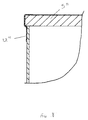
- Figures 6, 7 and 8 illustrate different variants of the seal around the edge of the lid 5, for forming the air-tight connection between the lid and the chamber.
- a seal 12' of "Neoprene” or EPDM closed cell foam fits over the upper edge of the chamber by means of a slot provided in the seal, and serves both to provide the necessary air-tight seal with the lid 5' during testing and afterwards, may remain in place to form the seal with either a corbel unit or extension piece or a suitable lid.
- a third variant of the seal 12''' simply comprises an endless band of Nitrile rubber which is stretched around and over the joint between the lid 5'', sealing the joint as vacuum is applied.
- the testing apparatus 10 (represented by the embodiment having a one piece lid 5 shown fitted to the chamber 24) is remote from a self contained unit 30 housing the vacuum pump, vacuum indicator/monitoring means as well as other utilities such as timers and performance monitoring.
- Unit 30 is installed at a minimum safe distance away from the installation, and linked to the testing apparatus 10 via respective pipes 35, 37 of the required length. Thus, any fire risk due to electrical sparking in the possible presence of petrol vapour is eliminated.
- FIG 10 illustrates the preferred embodiment of the invention, comprising the hinged lid with panels 4 and 6, each incorporating a window 4a, 6a.
- the lid has a central structural unit 2 bearing a carrying handle 2a, and has fabric handles 43 at each end of central unit 2 and at two opposed corners of the lid.
- the pipes 35, 37 link the lid (shown in Fig 10 on top of the access chamber 24) to a control unit 46 comprising essentially a dedicated micro-processor 40 and user interface 42, the latter comprising a series of push buttons and LEDs - depth setting selector 50 (ranging from 0.6m to 3m), start test button 52 and associated test progress LEDs, test result display 54, emergency stop button 56 and power on LED 58, the control unit being connected to the electrical power supply by means of cable 48.
- a vent pipe 45 carries the evacuated air from inside the chamber (which may include fuel vapour) to be exhausted to the atmosphere at a safe distance, at least 5m away from any electrical equipment.
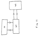
- the function of the apparatus is illustrated schematically in Figure 11 - the selection and start test information is transmitted from user interface 42 to the microprocessor 40 which selects the appropriate test program, according to the chamber depth selected.
- the micro-processor controls the operation of the evacuation means and the vacuum monitoring means (indicated generally by 10), the vacuum monitoring means then feeding the information on vacuum level back to the micro-processor which works out the rate of decay (as measured over a pre-determined period of time), compares this value with the stored empirical values, and sends the result back to the user interface 42 to be displayed accordingly on the test result LED display 54.
Landscapes
- Physics & Mathematics (AREA)
- General Physics & Mathematics (AREA)
- Examining Or Testing Airtightness (AREA)
Applications Claiming Priority (6)
| Application Number | Priority Date | Filing Date | Title |
|---|---|---|---|
| GBGB9708763.9A GB9708763D0 (en) | 1997-04-30 | 1997-04-30 | Testing of access chamber installation |
| GB9708763 | 1997-04-30 | ||
| GBGB9716835.5A GB9716835D0 (en) | 1997-04-30 | 1997-08-11 | Testing of access chamber system installation |
| GB9716835 | 1997-08-11 | ||
| US08/942,968 US5992220A (en) | 1997-04-30 | 1997-10-03 | Testing of access chamber system installation |
| US942968 | 1997-10-03 |
Publications (3)
| Publication Number | Publication Date |
|---|---|
| EP0875746A2 true EP0875746A2 (de) | 1998-11-04 |
| EP0875746A3 EP0875746A3 (de) | 1999-06-16 |
| EP0875746B1 EP0875746B1 (de) | 2005-11-16 |
Family
ID=27268827
Family Applications (1)
| Application Number | Title | Priority Date | Filing Date |
|---|---|---|---|
| EP19980201291 Expired - Lifetime EP0875746B1 (de) | 1997-04-30 | 1998-04-22 | Vorrichtung zur Leckprüfung an einem Zugangsraum einer Anlage |
Country Status (4)
| Country | Link |
|---|---|
| EP (1) | EP0875746B1 (de) |
| DE (1) | DE69832323T2 (de) |
| ES (1) | ES2253805T3 (de) |
| PL (1) | PL326042A1 (de) |
Cited By (1)
| Publication number | Priority date | Publication date | Assignee | Title |
|---|---|---|---|---|
| ITBZ20100004A1 (it) * | 2010-01-29 | 2011-07-30 | Wolftank Systems Spa Ag | Sistema per il monitoraggio di un impianto di stoccaggio per combustibile |
Family Cites Families (4)
| Publication number | Priority date | Publication date | Assignee | Title |
|---|---|---|---|---|
| JPS5956044A (ja) * | 1982-09-21 | 1984-03-31 | Toyota Motor Corp | 保温蓋 |
| US4754638A (en) * | 1986-05-23 | 1988-07-05 | Antares Engineering, Inc. | Apparatus and method for leak testing automotive wheel rims |
| US4685585A (en) * | 1986-10-09 | 1987-08-11 | Robbins Howard J | Double wall tank manway system |
| US5297529A (en) * | 1993-01-27 | 1994-03-29 | Siemens Automotive Limited | Positive pressure canister purge system integrity confirmation |
-
1998
- 1998-04-22 DE DE69832323T patent/DE69832323T2/de not_active Expired - Fee Related
- 1998-04-22 ES ES98201291T patent/ES2253805T3/es not_active Expired - Lifetime
- 1998-04-22 EP EP19980201291 patent/EP0875746B1/de not_active Expired - Lifetime
- 1998-04-28 PL PL32604298A patent/PL326042A1/xx unknown
Cited By (2)
| Publication number | Priority date | Publication date | Assignee | Title |
|---|---|---|---|---|
| ITBZ20100004A1 (it) * | 2010-01-29 | 2011-07-30 | Wolftank Systems Spa Ag | Sistema per il monitoraggio di un impianto di stoccaggio per combustibile |
| EP2352004B1 (de) * | 2010-01-29 | 2017-07-26 | Wolftank Systems AG | Überwachungssystem für eine Brennstoffspeicheranlage |
Also Published As
| Publication number | Publication date |
|---|---|
| EP0875746B1 (de) | 2005-11-16 |
| EP0875746A3 (de) | 1999-06-16 |
| DE69832323D1 (de) | 2005-12-22 |
| PL326042A1 (en) | 1998-11-09 |
| ES2253805T3 (es) | 2006-06-01 |
| DE69832323T2 (de) | 2006-08-10 |
Similar Documents
| Publication | Publication Date | Title |
|---|---|---|
| CA1168521A (en) | Leak detector | |
| US5887477A (en) | Apparatus and method for testing waterproofness and breathing fabrics | |
| US7578169B2 (en) | Method and apparatus for continuously monitoring interstitial regions in gasoline storage facilities and pipelines | |
| US7051579B2 (en) | Method and apparatus for continuously monitoring interstitial regions in gasoline storage facilities and pipelines | |
| EP0875746B1 (de) | Vorrichtung zur Leckprüfung an einem Zugangsraum einer Anlage | |
| US5216914A (en) | Methods and systems for the negative pressure testing of underground storage tanks containing highly vaporous hydrocarbon liquids | |
| US4413503A (en) | Method of detecting leaks in a large storage tank | |
| US20010013246A1 (en) | Vacuum testing of access chamber system installation through monitoring of vacuum decay | |
| US5810040A (en) | Container for storing liquids | |
| KR101604398B1 (ko) | 맨홀 수밀 검사방법 및 검사장치 | |
| CN213205948U (zh) | 一种液压泵性能测试装置 | |
| US5992220A (en) | Testing of access chamber system installation | |
| US7216530B2 (en) | Fluid containment element leak detection apparatus and method | |
| KR101815804B1 (ko) | 개별진공압밀공법의 배수재 진공압 검사장치 | |
| JP3062530B2 (ja) | 漏れ検出方法及び漏れ検出装置 | |
| CN219134445U (zh) | 便于气密性检测的冲浪板 | |
| CA3007193A1 (en) | Apparatus and methods for testing the integrity of containment sumps | |
| CN216645745U (zh) | 油站人孔井的负压密闭检测系统 | |
| CN211347283U (zh) | 一种食品安全监测装置 | |
| JPH06323948A (ja) | 消防用ホースの検査装置及び検査方法 | |
| CN208254738U (zh) | 管道密封性测试装置 | |
| CN219641162U (zh) | 一种建筑用防水材料试漏检测装置 | |
| JP3024456B2 (ja) | 中空容器の気密性検査方法 | |
| JP2558419Y2 (ja) | ガス警報器用点検装置 | |
| JP4174682B2 (ja) | 地下タンクの漏油検知装置 |
Legal Events
| Date | Code | Title | Description |
|---|---|---|---|
| PUAI | Public reference made under article 153(3) epc to a published international application that has entered the european phase |
Free format text: ORIGINAL CODE: 0009012 |
|
| AK | Designated contracting states |
Kind code of ref document: A2 Designated state(s): BE DE ES FR GB IT |
|
| AX | Request for extension of the european patent |
Free format text: AL;LT;LV;MK;RO;SI |
|
| PUAL | Search report despatched |
Free format text: ORIGINAL CODE: 0009013 |
|
| AK | Designated contracting states |
Kind code of ref document: A3 Designated state(s): AT BE CH CY DE DK ES FI FR GB GR IE IT LI LU MC NL PT SE |
|
| AX | Request for extension of the european patent |
Free format text: AL;LT;LV;MK;RO;SI |
|
| 17P | Request for examination filed |
Effective date: 19991216 |
|
| AKX | Designation fees paid | ||
| RBV | Designated contracting states (corrected) |
Designated state(s): BE DE ES FR GB IT |
|
| REG | Reference to a national code |
Ref country code: DE Ref legal event code: 8566 |
|
| 17Q | First examination report despatched |
Effective date: 20040219 |
|
| GRAP | Despatch of communication of intention to grant a patent |
Free format text: ORIGINAL CODE: EPIDOSNIGR1 |
|
| RTI1 | Title (correction) |
Free format text: APPARATUS FOR LEAK TESTING ON AN ACCESS CHAMBER SYSTEM INSTALLATION |
|
| GRAS | Grant fee paid |
Free format text: ORIGINAL CODE: EPIDOSNIGR3 |
|
| GRAA | (expected) grant |
Free format text: ORIGINAL CODE: 0009210 |
|
| AK | Designated contracting states |
Kind code of ref document: B1 Designated state(s): BE DE ES FR GB IT |
|
| REG | Reference to a national code |
Ref country code: GB Ref legal event code: FG4D |
|
| REF | Corresponds to: |
Ref document number: 69832323 Country of ref document: DE Date of ref document: 20051222 Kind code of ref document: P |
|
| PGFP | Annual fee paid to national office [announced via postgrant information from national office to epo] |
Ref country code: GB Payment date: 20060419 Year of fee payment: 9 |
|
| PGFP | Annual fee paid to national office [announced via postgrant information from national office to epo] |
Ref country code: FR Payment date: 20060425 Year of fee payment: 9 |
|
| PGFP | Annual fee paid to national office [announced via postgrant information from national office to epo] |
Ref country code: DE Payment date: 20060427 Year of fee payment: 9 |
|
| PGFP | Annual fee paid to national office [announced via postgrant information from national office to epo] |
Ref country code: ES Payment date: 20060428 Year of fee payment: 9 |
|
| PGFP | Annual fee paid to national office [announced via postgrant information from national office to epo] |
Ref country code: IT Payment date: 20060430 Year of fee payment: 9 |
|
| REG | Reference to a national code |
Ref country code: ES Ref legal event code: FG2A Ref document number: 2253805 Country of ref document: ES Kind code of ref document: T3 |
|
| PGFP | Annual fee paid to national office [announced via postgrant information from national office to epo] |
Ref country code: BE Payment date: 20060614 Year of fee payment: 9 |
|
| ET | Fr: translation filed | ||
| PLBE | No opposition filed within time limit |
Free format text: ORIGINAL CODE: 0009261 |
|
| STAA | Information on the status of an ep patent application or granted ep patent |
Free format text: STATUS: NO OPPOSITION FILED WITHIN TIME LIMIT |
|
| 26N | No opposition filed |
Effective date: 20060817 |
|
| GBPC | Gb: european patent ceased through non-payment of renewal fee |
Effective date: 20070422 |
|
| BERE | Be: lapsed |
Owner name: *FIBRESEC HOLDINGS LTD Effective date: 20070430 |
|
| PG25 | Lapsed in a contracting state [announced via postgrant information from national office to epo] |
Ref country code: DE Free format text: LAPSE BECAUSE OF NON-PAYMENT OF DUE FEES Effective date: 20071101 |
|
| PG25 | Lapsed in a contracting state [announced via postgrant information from national office to epo] |
Ref country code: BE Free format text: LAPSE BECAUSE OF NON-PAYMENT OF DUE FEES Effective date: 20070430 |
|
| PG25 | Lapsed in a contracting state [announced via postgrant information from national office to epo] |
Ref country code: GB Free format text: LAPSE BECAUSE OF NON-PAYMENT OF DUE FEES Effective date: 20070422 |
|
| REG | Reference to a national code |
Ref country code: ES Ref legal event code: FD2A Effective date: 20070423 |
|
| PG25 | Lapsed in a contracting state [announced via postgrant information from national office to epo] |
Ref country code: FR Free format text: LAPSE BECAUSE OF NON-PAYMENT OF DUE FEES Effective date: 20070430 |
|
| PG25 | Lapsed in a contracting state [announced via postgrant information from national office to epo] |
Ref country code: ES Free format text: LAPSE BECAUSE OF NON-PAYMENT OF DUE FEES Effective date: 20070423 |
|
| PG25 | Lapsed in a contracting state [announced via postgrant information from national office to epo] |
Ref country code: IT Free format text: LAPSE BECAUSE OF NON-PAYMENT OF DUE FEES Effective date: 20070422 |