EP2351680B1 - Système et procédé de surveillance d'une voie ferrée - Google Patents
Système et procédé de surveillance d'une voie ferrée Download PDFInfo
- Publication number
- EP2351680B1 EP2351680B1 EP10170811A EP10170811A EP2351680B1 EP 2351680 B1 EP2351680 B1 EP 2351680B1 EP 10170811 A EP10170811 A EP 10170811A EP 10170811 A EP10170811 A EP 10170811A EP 2351680 B1 EP2351680 B1 EP 2351680B1
- Authority
- EP
- European Patent Office
- Prior art keywords
- optical signal
- rail
- bragg gratings
- reflected
- period
- Prior art date
- Legal status (The legal status is an assumption and is not a legal conclusion. Google has not performed a legal analysis and makes no representation as to the accuracy of the status listed.)
- Expired - Lifetime
Links
- 238000012544 monitoring process Methods 0.000 title claims description 10
- 238000000034 method Methods 0.000 title claims description 5
- 230000003287 optical effect Effects 0.000 claims description 48
- 239000013307 optical fiber Substances 0.000 claims description 14
- 239000000835 fiber Substances 0.000 description 14
- 230000007246 mechanism Effects 0.000 description 10
- 238000005259 measurement Methods 0.000 description 9
- 238000001514 detection method Methods 0.000 description 4
- 238000004891 communication Methods 0.000 description 3
- 230000005855 radiation Effects 0.000 description 2
- 230000007423 decrease Effects 0.000 description 1
- 229920006335 epoxy glue Polymers 0.000 description 1
- 239000002657 fibrous material Substances 0.000 description 1
- 238000009434 installation Methods 0.000 description 1
- 238000005457 optimization Methods 0.000 description 1
- 230000000737 periodic effect Effects 0.000 description 1
- 238000000926 separation method Methods 0.000 description 1
- 230000003068 static effect Effects 0.000 description 1
- 238000003466 welding Methods 0.000 description 1
Images
Classifications
-
- B—PERFORMING OPERATIONS; TRANSPORTING
- B61—RAILWAYS
- B61L—GUIDING RAILWAY TRAFFIC; ENSURING THE SAFETY OF RAILWAY TRAFFIC
- B61L1/00—Devices along the route controlled by interaction with the vehicle or vehicle train, e.g. pedals
- B61L1/16—Devices for counting axles; Devices for counting vehicles
- B61L1/163—Detection devices
- B61L1/166—Optical
-
- B—PERFORMING OPERATIONS; TRANSPORTING
- B61—RAILWAYS
- B61L—GUIDING RAILWAY TRAFFIC; ENSURING THE SAFETY OF RAILWAY TRAFFIC
- B61L23/00—Control, warning, or like safety means along the route or between vehicles or vehicle trains
- B61L23/04—Control, warning, or like safety means along the route or between vehicles or vehicle trains for monitoring the mechanical state of the route
- B61L23/041—Obstacle detection
Definitions
- the present invention relates to railway monitoring systems.
- Axle counter and wheel imbalance weighting system are two popular measurement mechanisms among them.
- an axle counter uses magnetic fields to counter the axles of a passing train
- a typical wheel imbalance weighting system uses a strain gauge sensor in a bridge circuit to measure the load of the train.
- Disadvantages exist with these conventional mechanisms for example, installation of some conventional measurement mechanism may not be easy. More importantly, performance of these conventional mechanisms may be affected by external electromagnet radiation. This may deteriorate the reliability of these conventional measurement mechanisms, especially in an AC railway system, since lots of noises could be introduced to these conventional measurement mechanisms.
- these conventional measurement mechanisms need to be individually installed onto the railway. This may not be convenient if a significant number of measurement mechanisms are needed. Neither can it be convenient to set up a centralized railway monitoring system due to the complexity of collection of all the results from each individual measurement mechanism.
- an optical sensor emits a vehicle detection light signal when a railway vehicle is present in a track section.
- a reference light signal is also generated by a light emission source.
- a detector in optical communication with the optical sensor receives the vehicle detection light signal.
- Information present in the vehicle detection light signal is interpreted by a processor to detect the railway vehicle.
- the sensor may comprise an elongated optical fiber extending along the track section or a plurality of cascaded localised sensors. It is also disclosed that the sensor may be utilised as a communication medium to pass communication data between opposite ends of the track section. Depending on the exigencies of the particular application, the sensor may be located within the track section in a number of ways.
- a railway monitoring system includes the features of claim 1.
- both the emitter and the analyzer are connected to an end of the fiber, and the first altered optical signal is a signal reflected by the fiber towards the end.
- a process for monitoring a railway system includes the features of claim 12.
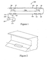
- an exemplary railway monitoring system 100 of the present invention includes an optical fiber 101 having eight Bragg gratings S1-S8, which are created in the fiber 101 and which are selectively attached to a pair of tracks 103,105 of a railway respectively.
- An optical signal emitter 107 providing a broad band light source is connected to one end 109 of the fiber 101 for emitting an optical signal into the fiber 101.
- Each Bragg grating S1-S8 has a distinct reflected wavelength (to be discussed with reference to Figure 3 ) and reflects an optical signal towards the end 109, and each reflected optical signal contains information reflecting variance of a characteristic of a part of the tracks where the Bragg gratings S1-S8 are mounted.
- the wave band of the optical signal from the emitter 105 is broad enough to cover all the reflected wavelengths of the Bragg gratings S1-S8 in the exemplary embodiment,
- An optical signal interrogator 111 also connected to the end 109, receives these reflected signals and further detects a shift in the wavelength of each reflected optical signal as discussed in details below. The interrogator then passes the detection results to a computer 113 for analysis thereof. Based on these reflected optical signals, the interrogator 111 and the computer 113 are able to ascertain certain situations in the tracks 103, 105 and further to monitor the railway. It is noted that the exemplary system merely has an optical fiber in the railway region and therefore is not affected by external electromagnet radiations.
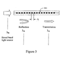
- a Bragg grating 301 is a single modus fiber with permanent periodic variation of the refractive index over a fiber length of, for example 0.1 to 10 cm.
- the variation in the refractive index is established by illuminating the fiber with a UV laser.
- the Bragg grating 301 reflects light with a distinct reflected wavelength that depends upon the refractive index and the space related period of the variation of the refractive index (the grating period), while light beyond this wavelength will pass through the grating more or less unhindered.
- the light reflected by the Bragg grating 301 will exhibit a wavelength that varies as a function of a measurable quantity that changes the refractive index of the fiber material grating and/or the fiber length in the grating zone (grating period). Changes in either the tension in the fiber or the environment temperature will therefore lead to shift in the wavelength of the optical signal reflected by the Bragg grating 301.
- each Bragg grating S1-S8 has a distinct reflected wavelength
- the interrogator can identify the reflected optical signals by these Bragg gratings so long as the wavelength interval between the Bragg gratings is designed to be longer than the allowable maximum shift in the wavelength of the reflected signals, which shift can be caused by changes in either the tension in the fiber or the environment temperature.
- each Bragg grating S1-S8 is mounted to the track through Epoxy glue or welding in a direction parallel to the tracks 103, 105.
- Each Bragg grating is pre-strained to avoid the Bragg gratings losing tension in operation.
- each Bragg grating extends at least substantially parallel to its respective track.
- the portion of the track experiences a tensile strain due to the pressure or weight exerted thereon by the axle of the train. Since the Bragg grating S1 is fixedly mounted to the track 103 and extends parallel to the track 103, the Bragg grating S1 experiences the same tensile strain as the track. Such a tensile strain leads to a shift in the wavelength of the optical signal reflected by the Bragg grating S1, and this shift is proportional to the tensile strain both the Bragg grating and the track experience and correspondingly to the pressure exerted on the track.
- the system 100 By detecting this shift by the interrogator 111, the system 100 thereby obtains information relating to the tensile strain both the Bragg grating and the track experience and correspondingly the pressure exerted on the track.
- both the track and the Bragg grating S1 restore quickly such that the shift in the wavelength of the reflected signal by S1 decreases to zero accordingly, and the Bragg grating S1 is then ready for the next tensile strain, which may caused by another axle.
- the system 100 is able to ascertain certain situations in the tracks 103, 105 and further to monitor the railway.
- the exemplary system 100 can be used to count the number of axles of a passing train by counting the number of successive shifts in the wavelength of optical signal reflected by one of the Bragg gating.
- the system 100 is also able to determine the end of the train if it does not detect any shifts in the wavelength during a predetermined period, which is designed to be substantially longer than a possible maximum period of time for two adjacent axles to pass through the Bragg grating.
- the exemplary system 100 may easily ascertain the instantaneous speed of the train by using the period of time taken for successive axles to pass through a particular Bragg grating.
- the exemplary system 100 can easily find out the start and end of a passing train.
- the exemplary system 100 can further ascertain a period of time between two successive trains by constantly measuring a period of time between two successive shifts in the wavelength of the first reflected optical signal; comparing the period of time between two successive shifts with a predetermined threshold value; and determining the period of time between two successive trains if the period of time between two successive shifts exceeds the predetermined threshold value.
- the information about the period of time between two successive trains can then be used by the exemplary system 100 to control the speed of these two trains.
- the exemplary system 100 may trigger a flooding alert.
- the predetermined period is preset to be at least longer than the possible maximum period of time for two adjacent axles to pass through a particular Bragg grating.
- the system 100 does not detect any substantial changes of the shift in the wavelength of a reflected optical signal during the predetermined period, it is very likely that there are not any trains passing through the Bragg grating. Therefore, the shift in the reflected wavelength is very likely caused by the change in the environment temperature, and a very possible reason for the change in the environment temperature is the occurrence of flooding.
- the computer can process the data received from the interrogator to evaluate whether there is any imbalance between the two tracks of the rail.
- the weight of a train can be measured by adding all the strain measurements along the entire train.
- Such a weighting system is particularly useful in the situations when the train is static or moves at a relatively low speed.
- the Bragg gratings S1-S8 are selectively positioned on the tracks 103, 105.
- the spacing between S1 and S2, S3 and S4, S5 and S6, and S7 and S8 is designed to be in line with the spacing between two adjacent axles of a particular train, while the spacing between S2 and S3, and S6 and S7 is designed to be in line with the spacing between the boogies of this particular train.
- each Bragg grating can be mounted to the tracks in a direction non-parallel to its respective track.
- the tensile strain the Bragg gratings experience may not be the same as the one the tracks experience. But the tensile strain the Bragg gratings experience is still relevant, if not exactly proportional to the one the tracks experience. Therefore, the system 100 is still able to ascertain the tensile strain the tracks experience based on the shifts in the wavelengths of the optical signals reflected by the Bragg gratings.
- the exemplary system 100 uses the optical signals reflected by the Bragg gratings. It can be understood from Figure 3 that the optical signal transmitted through all the Bragg gratings can also be used for similar analysis. In this case, the interrogator needs to be connected to the other end of the fiber.
Landscapes
- Engineering & Computer Science (AREA)
- Mechanical Engineering (AREA)
- Automation & Control Theory (AREA)
- Length Measuring Devices By Optical Means (AREA)
- Optical Transform (AREA)
- Train Traffic Observation, Control, And Security (AREA)
- Photometry And Measurement Of Optical Pulse Characteristics (AREA)
- Measuring Temperature Or Quantity Of Heat (AREA)
Claims (13)
- Un système de surveillance de chemin de fer, comportant :une fibre optique (101) ayant une pluralité de parties espacées sur la longueur de la fibre optique, chaque partie de la pluralité pouvant être attachée à une portion respective d'un rail parmi une paire de rails (103, 105) d'une voie ;un émetteur de signal optique (107) connecté à la fibre optique (101) pour émettre un signal optique dans la fibre optique ; etun analyseur de signal optique (111) connecté à la fibre optique pour recevoir et analyser des signaux optiques altérés ;caractérisé en ce que la pluralité de parties comporte une première pluralité de réseaux de Bragg (S), chaque réseau de Bragg (S) étant précontraint dans une direction au moins substantiellement parallèle audit un rail et ayant une longueur d'onde réfléchie distincte qui est altérée lors d'un changement dans la contrainte émanant d'une portion respective du rail, et ledit analyseur de signal optique (111) reçoit des signaux optiques altérés sous la forme de signaux réfléchis et est adapté pour détecter des modifications dans les longueurs d'onde des signaux optiques altérés des réseaux de Bragg, une modification étant révélatrice d'un changement dans la contrainte au niveau d'une portion respective du rail.
- Le système de la revendication 1, dans lequel l'émetteur (107) et l'analyseur (111) sont tous les deux connectés à la même extrémité de la fibre optique.
- Le système de la revendication 1, dans lequel la première pluralité de réseaux de Bragg (S) est attachée audit un rail (103, 105) de telle sorte que la première pluralité de réseaux de Bragg subisse une même contrainte de traction que ledit un rail.
- Le système de la revendication 1, comportant un compteur connecté à l'analyseur de signal optique (111) pour compter le nombre de modifications dans la longueur d'onde d'un premier signal optique réfléchi, dans lequel ledit nombre porte sur le nombre d'essieux d'un train qui passe sur l'un des réseaux de Bragg.
- Le système de la revendication 1, comportant une horloge connectée à l'analyseur de signal optique (111) pour mesurer une période de temps entre un nombre prédéterminé de modifications successives dans la longueur d'onde d'un premier signal optique réfléchi de façon à déterminer une vitesse du train.
- Le système de la revendication 1, comportant de plus un processeur (113) connecté à l'analyseur de signal optique (111), dans lequel le processeur détermine une période de temps entre deux trains successifs en
mesurant constamment une période de temps entre deux modifications successives dans la longueur d'onde d'un premier signal optique réfléchi ;
comparant ladite période de temps entre deux modifications successives avec une valeur de seuil prédéterminée ; et
déterminant la période de temps entre deux trains successifs si ladite période de temps entre deux modifications successives dépasse la valeur de seuil prédéterminée. - Le système de la revendication 1, dans lequel la caractéristique de la première pluralité de réseaux de Bragg (S) porte de plus sur une période de réseau de la première pluralité de réseaux de Bragg, et dans lequel la période de réseau est variable en correspondance avec un changement dans une température ambiante subie pas la première pluralité de réseaux de Bragg.
- Le système de la revendication 7, dans lequel l'analyseur de signal optique (111) détermine un changement dans la température ambiante en
déterminant s'il y a une modification dans la longueur d'onde d'un premier signal optique réfléchi ; et
déterminant simultanément si un changement de la sorte varie durant une période prédéterminée. - Le système de la revendication 1, comportant de plus une deuxième pluralité de réseaux de Bragg (S) pouvant être attachée à l'autre rail (103, 105) pour déterminer une variation d'une caractéristique de l'autre rail, dans lequel la deuxième pluralité de réseaux de Bragg produit d'autres signaux optiques réfléchis recevables par l'analyseur de signal optique, dans lequel une modification dans la longueur d'onde des autres signaux optiques réfléchis en correspondance avec la variation de la caractéristique de l'autre rail est détectable par l'analyseur de signal optique.
- Le système de la revendication 9, comportant de plus un processeur (113) connecté à l'analyseur de signal optique (111) pour déterminer un déséquilibre sur la paire de rails sur la base des modifications dans les longueurs d'onde des premiers et deuxièmes signaux optiques réfléchis.
- Le système de la revendication 10, dans lequel les première et deuxième pluralités de réseaux de Bragg (S) sont positionnées en correspondance avec l'espacement entre les essieux et les bogies d'un train pour déterminer une caractéristique du train.
- Un procédé pour surveiller un système de chemin de fer, comportant :placer une fibre optique (101) ayant une pluralité de parties le long d'un rail d'une voie ;contraindre dans une direction axiale et attacher ladite pluralité de parties audit rail de telle sorte qu'une caractéristique de la fibre optique varie avec la contrainte du rail ;émettre un signal optique le long de ladite fibre optique ; etanalyser un signal optique altéré reçu de la fibre optique pour déterminer des informations relatives à ladite voie ;dans lequel la pluralité de parties comporte une pluralité de réseaux de Bragg (S), chaque réseau de Bragg (S) ayant une longueur d'onde réfléchie distincte et en ce que l'analyseur de signal optique (111) détecte une modification dans les longueurs d'onde du signal optique altéré lors d'un changement dans la contrainte d'un réseau de Bragg pour déterminer la contrainte du rail.
- Le procédé de la revendication 12, dans lequel lesdites informations portent sur un train ou un véhicule sur ladite voie.
Priority Applications (1)
| Application Number | Priority Date | Filing Date | Title |
|---|---|---|---|
| EP10170811A EP2351680B1 (fr) | 2004-03-29 | 2004-03-29 | Système et procédé de surveillance d'une voie ferrée |
Applications Claiming Priority (2)
| Application Number | Priority Date | Filing Date | Title |
|---|---|---|---|
| EP10170811A EP2351680B1 (fr) | 2004-03-29 | 2004-03-29 | Système et procédé de surveillance d'une voie ferrée |
| EP04251840A EP1582430A1 (fr) | 2004-03-29 | 2004-03-29 | Système et procédé de surveillance d'une voie ferrée |
Related Parent Applications (2)
| Application Number | Title | Priority Date | Filing Date |
|---|---|---|---|
| EP04251840 Previously-Filed-Application | 2004-03-29 | ||
| EP04251840.7 Division | 2004-03-29 |
Publications (3)
| Publication Number | Publication Date |
|---|---|
| EP2351680A1 EP2351680A1 (fr) | 2011-08-03 |
| EP2351680A3 EP2351680A3 (fr) | 2011-11-16 |
| EP2351680B1 true EP2351680B1 (fr) | 2012-12-12 |
Family
ID=34878316
Family Applications (2)
| Application Number | Title | Priority Date | Filing Date |
|---|---|---|---|
| EP04251840A Ceased EP1582430A1 (fr) | 2004-03-29 | 2004-03-29 | Système et procédé de surveillance d'une voie ferrée |
| EP10170811A Expired - Lifetime EP2351680B1 (fr) | 2004-03-29 | 2004-03-29 | Système et procédé de surveillance d'une voie ferrée |
Family Applications Before (1)
| Application Number | Title | Priority Date | Filing Date |
|---|---|---|---|
| EP04251840A Ceased EP1582430A1 (fr) | 2004-03-29 | 2004-03-29 | Système et procédé de surveillance d'une voie ferrée |
Country Status (8)
| Country | Link |
|---|---|
| US (1) | US8861973B2 (fr) |
| EP (2) | EP1582430A1 (fr) |
| JP (1) | JP2007530352A (fr) |
| CN (1) | CN1676389B (fr) |
| CA (1) | CA2561874C (fr) |
| ES (1) | ES2401127T3 (fr) |
| HK (1) | HK1082479A1 (fr) |
| WO (1) | WO2005093971A1 (fr) |
Cited By (2)
| Publication number | Priority date | Publication date | Assignee | Title |
|---|---|---|---|---|
| RU2556133C1 (ru) * | 2014-06-04 | 2015-07-10 | Открытое Акционерное Общество "Российские Железные Дороги" | Система интервального регулирования движения поездов на базе радиоканала |
| RU2583397C1 (ru) * | 2014-12-12 | 2016-05-10 | Открытое акционерное общество "Научно-исследовательский и проектно-конструкторский институт информатизации, автоматизации и связи на железнодорожном транспорте" (ОАО "НИИАС") | Система для интервального регулирования движения поездов на перегонах |
Families Citing this family (59)
| Publication number | Priority date | Publication date | Assignee | Title |
|---|---|---|---|---|
| US20070031084A1 (en) * | 2005-06-20 | 2007-02-08 | Fibera, Inc. | Trafic monitoring system |
| EP2056492A4 (fr) * | 2006-08-07 | 2016-07-06 | Hamamatsu Photonics Kk | Système de communication optique mobile et procédé de communication optique mobile |
| ITBN20060004A1 (it) * | 2006-09-20 | 2006-12-20 | Antonello Cutolo | Sistema di trasmissione in fibra ottica per il monitoraggio dei parametri ed il miglioramento della sicurezza di una linea ferroviaria |
| CN1936520B (zh) * | 2006-10-13 | 2011-08-31 | 北京东方瑞威科技发展有限公司 | 一种光纤传感式轨道衡的数据处理方法 |
| CN100460256C (zh) * | 2006-11-22 | 2009-02-11 | 北京东方瑞威科技发展有限公司 | 光纤偏载仪 |
| CN100460827C (zh) * | 2006-12-29 | 2009-02-11 | 北京交通大学 | 利用相干性光纤光栅组实现列车定位和实时追踪的方法 |
| JP5385516B2 (ja) * | 2007-07-10 | 2014-01-08 | エヌ・ティ・ティ・インフラネット株式会社 | 変形量センサ、変形量測定装置、変形量測定方法 |
| CN101377524B (zh) * | 2007-08-30 | 2011-02-16 | 北京佳讯飞鸿电气股份有限公司 | 基于钢轨形变/应力参数的车辆测速方法 |
| CN101376392B (zh) * | 2007-08-30 | 2011-02-16 | 北京佳讯飞鸿电气股份有限公司 | 基于钢轨形变或应力参数的车辆计轴方法 |
| CN101428634B (zh) * | 2008-03-14 | 2011-04-06 | 方阵(北京)科技有限公司 | 一种计轴传感器 |
| ITVR20080047A1 (it) * | 2008-04-21 | 2009-10-22 | Ace Snc | Procedimento e impianto per la misurazione e il monitoraggio esteso dello stato tensionale del lungo binario saldato (cwr) |
| JP5289097B2 (ja) * | 2009-02-26 | 2013-09-11 | 大同信号株式会社 | 踏切警報適正化システム及びその要部装置 |
| ITTO20090176A1 (it) * | 2009-03-10 | 2010-09-11 | Ansaldo Sts Spa | Sistema per il monitoraggio in tempo reale dello stato di usura/integrita' funzionale di sistemi di movimentazione di scambi ferroviari |
| CN101692625B (zh) * | 2009-10-30 | 2012-07-04 | 中铁八局集团电务工程有限公司 | 一种铁路区间多业务多点接入单光纤传输系统 |
| EP2368782A1 (fr) * | 2010-03-19 | 2011-09-28 | Mer Mec S.P.A. | Procédé et dispositif pour la détection en temps réel d'un état d'occupation de sections de chemin de fer d'après des capteurs FBG |
| CN101863278A (zh) * | 2010-06-03 | 2010-10-20 | 西南交通大学 | 基于光栅反射谱展宽的高速铁路计轴装置 |
| ES2394696B1 (es) * | 2010-12-10 | 2013-12-11 | Eugenio VELASCO PAVON | Sistema detector de nivel de agua en vías de ferrocarril |
| CN102108657B (zh) * | 2011-02-14 | 2012-07-04 | 武汉理工大学 | 光纤光栅传感无砟轨道结构状态监测方法及装置 |
| ITBN20110004A1 (it) * | 2011-05-24 | 2012-11-25 | Ansaldo Sts Spa | Sistema per il monitoraggio del peso e delle anomalie di ruote di materiale rotabile in movimento |
| CN102243348B (zh) * | 2011-07-12 | 2014-02-12 | 中国科学院半导体研究所 | 在钢轨上布设光纤的装置 |
| CN102407865A (zh) * | 2011-08-08 | 2012-04-11 | 黄力华 | 一种高速铁路列车实时测速定位安全系统 |
| GB201201703D0 (en) | 2012-02-01 | 2012-03-14 | Qinetiq Ltd | Detecting train separation |
| GB201201768D0 (en) * | 2012-02-01 | 2012-03-14 | Qinetiq Ltd | Control of transport networks |
| DE102012213499A1 (de) * | 2012-07-31 | 2014-02-06 | Siemens Aktiengesellschaft | Fahrzeugortung |
| DE102012213487A1 (de) * | 2012-07-31 | 2014-02-06 | Siemens Aktiengesellschaft | Schienenfahrzeugortung |
| DE102012222471A1 (de) | 2012-12-06 | 2014-06-12 | Siemens Aktiengesellschaft | Fahrzeugortung |
| ES2506590B1 (es) * | 2013-04-11 | 2015-07-28 | Universidad De Alcalá | Sistema sensor y procedimiento para detectar los ejes de los trenes utilizando fibra óptica y cámaras de tiempo de vuelo |
| DE102014100653B4 (de) * | 2014-01-21 | 2016-01-21 | fos4X GmbH | Schienenmesssystem |
| RU2560227C1 (ru) * | 2014-04-11 | 2015-08-20 | Открытое Акционерное Общество "Российские Железные Дороги" | Система контроля местоположения поезда |
| TR201405723A2 (tr) * | 2014-05-22 | 2015-09-21 | Sabri Haluk Goekmen | Ray kırığı ve çatlağını yansıma yöntemiyle algılayan sistem. |
| US9533698B2 (en) * | 2014-09-24 | 2017-01-03 | Bartlett & West, Inc. | Railway monitoring system |
| WO2016098134A1 (fr) * | 2014-12-16 | 2016-06-23 | Geointelligence S.R.L. | Système et procédé de surveillance de rails |
| CN106152961B (zh) * | 2015-01-16 | 2019-02-12 | 黄辉 | 一种光纤应变传感器及其制备方法 |
| EP3069952B1 (fr) * | 2015-03-20 | 2017-05-03 | Thales Deutschland GmbH | Procédé de comptage d'axe et dispositif compteur d'axe |
| CN104931716B (zh) * | 2015-05-18 | 2018-03-13 | 上海工程技术大学 | 一种光纤测速装置 |
| AU2015401228A1 (en) | 2015-11-14 | 2017-06-01 | Beijing Oriental Railway Technology Development Co.,Ltd | Optical fiber detection device with steel rail as elastomer and railway overload and unbalanced load detection system |
| CN105444853A (zh) * | 2015-11-14 | 2016-03-30 | 北京东方瑞威科技发展股份有限公司 | 以钢轨作为弹性体的光纤检测装置、铁路超偏载检测系统 |
| GB201611326D0 (en) * | 2016-06-29 | 2016-08-10 | Optasense Holdings Ltd | Distributed fibre optic sensing for rail monitoring |
| EP3275763B1 (fr) * | 2016-07-27 | 2021-09-15 | Frauscher sensortechnik GmbH | Agencement de capteurs de surveillance de chemin de fer et procédé correspondant |
| CN106828543A (zh) * | 2017-03-13 | 2017-06-13 | 北京众成探知信息技术有限公司 | 一种光纤分布式列车监测系统 |
| US10317256B2 (en) * | 2017-04-14 | 2019-06-11 | Palo Alto Research Center Incorporated | Monitoring transportation systems |
| CN107171715B (zh) * | 2017-05-31 | 2023-10-31 | 中铁第四勘察设计院集团有限公司 | 一种铁路信号数据网系统及其连接方法 |
| CA3065320C (fr) | 2017-06-16 | 2023-09-05 | Saint-Gobain Adfors Canada, Ltd. | Textile de detection |
| US10907958B2 (en) | 2017-09-07 | 2021-02-02 | Frank J Smith | Railroad track defect detection apparatus and method |
| US11333837B2 (en) * | 2017-09-07 | 2022-05-17 | Murata Machinery, Ltd. | Optical communication system for rail-guided truck |
| DE102017216811A1 (de) * | 2017-09-22 | 2019-03-28 | Thales Management & Services Deutschland Gmbh | Verfahren zur Montage eines Schienenüberwachungselements |
| PL3459811T3 (pl) * | 2017-09-22 | 2022-02-14 | Thales Management & Services Deutschland Gmbh | Sposób montażu układu pomiaru odkształcenia, w szczególności do licznika osi i związane z nim zastosowanie |
| KR102377175B1 (ko) | 2017-09-28 | 2022-03-21 | 엘지디스플레이 주식회사 | 백라이트 유닛 및 이를 포함한 액정표시장치 |
| US10988151B2 (en) * | 2018-08-06 | 2021-04-27 | Alstom Transport Technologies | System and method for controlling a level crossing of a railway track |
| EP3892519A4 (fr) * | 2018-12-03 | 2022-01-26 | NEC Corporation | Système de surveillance de voie ferrée dispositif de surveillance de voie ferrée, procédé de surveillance de voie ferrée et support non transitoire lisible par ordinateur |
| US10614708B1 (en) * | 2019-01-28 | 2020-04-07 | Alstom Transport Technologies | Train detection system for a railway track section, associated railway track section, and associated method for detecting presence of a railway vehicle on a track section |
| CN110001717B (zh) * | 2019-01-30 | 2020-12-01 | 武汉理工大学 | 驼峰溜放过程监测系统及方法 |
| CN111071300B (zh) * | 2020-02-12 | 2021-12-14 | 太原理工大学 | 高速列车轨道交通故障安全监测预警系统和信号处理方法 |
| CN111751570B (zh) * | 2020-06-18 | 2023-10-27 | 武汉理工大学 | 用于磁悬浮列车测速定位的阵列光纤光栅传感系统与方法 |
| CN112429040A (zh) * | 2020-10-27 | 2021-03-02 | 衡阳市智谷科技发展有限公司 | 一种用于轨道交通的低成本导航定位方法 |
| CN113879358B (zh) * | 2021-10-29 | 2023-06-09 | 国能朔黄铁路发展有限责任公司 | 轨道状态监测设备及方法、控制装置和存储介质 |
| CN114604296B (zh) * | 2022-03-04 | 2023-10-31 | 中车青岛四方机车车辆股份有限公司 | 一种磁悬浮列车的定位系统及方法 |
| CN114659612B (zh) * | 2022-03-16 | 2024-05-03 | 武汉理工大学 | 一种基于光纤光栅阵列的轨道交通列车定位系统和方法 |
| CN114987579A (zh) * | 2022-05-26 | 2022-09-02 | 中车青岛四方机车车辆股份有限公司 | 一种轨道车辆及其测速定位系统 |
Family Cites Families (28)
| Publication number | Priority date | Publication date | Assignee | Title |
|---|---|---|---|---|
| JPS5617757A (en) * | 1979-07-20 | 1981-02-19 | Okura Denki Co Ltd | Train detector |
| US4654520A (en) * | 1981-08-24 | 1987-03-31 | Griffiths Richard W | Structural monitoring system using fiber optics |
| JPS62103533A (ja) * | 1985-10-31 | 1987-05-14 | Japanese National Railways<Jnr> | レ−ル軸力測定装置 |
| JPH0723093B2 (ja) * | 1989-04-12 | 1995-03-15 | 西武鉄道株式会社 | 乗車率測定方法 |
| JP2733391B2 (ja) * | 1991-06-06 | 1998-03-30 | 三菱電機株式会社 | 列車接近検知器 |
| US5330136A (en) * | 1992-09-25 | 1994-07-19 | Union Switch & Signal Inc. | Railway coded track circuit apparatus and method utilizing fiber optic sensing |
| IT1262407B (it) * | 1993-09-06 | 1996-06-19 | Finmeccanica Spa | Strumentazione utilizzante componenti in ottica integrata per la diagnostica di parti con sensori a fibra ottica inclusi o fissati sulla superficie. |
| NO302441B1 (no) * | 1995-03-20 | 1998-03-02 | Optoplan As | Fiberoptisk endepumpet fiber-laser |
| US5641956A (en) * | 1996-02-02 | 1997-06-24 | F&S, Inc. | Optical waveguide sensor arrangement having guided modes-non guided modes grating coupler |
| US5680489A (en) | 1996-06-28 | 1997-10-21 | The United States Of America As Represented By The Secretary Of The Navy | Optical sensor system utilizing bragg grating sensors |
| US6072567A (en) * | 1997-02-12 | 2000-06-06 | Cidra Corporation | Vertical seismic profiling system having vertical seismic profiling optical signal processing equipment and fiber Bragg grafting optical sensors |
| JP3410338B2 (ja) | 1997-08-25 | 2003-05-26 | 日本信号株式会社 | 限界支障報知装置 |
| DE19851931A1 (de) * | 1998-11-11 | 2000-05-25 | Alcatel Sa | Anordnung zur Erkennung von Schienenbrüchen und Eisenbahnschiene |
| BR9915956B1 (pt) * | 1998-12-04 | 2011-10-18 | sensor de pressão, e, método para sensoriar pressão. | |
| US6201237B1 (en) * | 1998-12-18 | 2001-03-13 | Corning Incorporated | Fiber optic sensor |
| US6751367B2 (en) * | 1999-04-02 | 2004-06-15 | Ifos, Inc. | Multiplexable fiber-optic strain sensor system with temperature compensation capability |
| US6377727B1 (en) * | 1999-05-25 | 2002-04-23 | Thomas & Betts International, Inc. | Passive temperature-compensating package for fiber Bragg grating devices |
| JP4009390B2 (ja) * | 1999-05-27 | 2007-11-14 | 清水建設株式会社 | ブラッグ格子型振動計 |
| EP1128171A1 (fr) | 2000-02-22 | 2001-08-29 | Sensor Line Gesellschaft für optoelektronische Sensoren mbH | Capteur de charge à fibre optique pour la detection des véhicules ferroviaires |
| DE10012291C1 (de) * | 2000-03-14 | 2001-09-20 | Reinhausen Maschf Scheubeck | Verfahren zur faseroptischen Temperaturmessung und faseroptischer Temperatursensor |
| CA2412041A1 (fr) * | 2000-06-29 | 2002-07-25 | Paulo S. Tubel | Procede et systeme permettant de surveiller des structures intelligentes mettant en oeuvre des capteurs optiques distribues |
| AU2001283043A1 (en) | 2000-08-01 | 2002-02-13 | The Government Of The United States Of America, As Represented By The Secretary Of The Navy | Optical sensing device containing fiber bragg gratings |
| JP2003065731A (ja) * | 2001-08-24 | 2003-03-05 | Mitsubishi Heavy Ind Ltd | 歪み計測装置 |
| JP3942864B2 (ja) | 2001-10-31 | 2007-07-11 | 財団法人鉄道総合技術研究所 | 軌道狂い計測方法及びその計測装置 |
| CA2559356C (fr) * | 2004-03-24 | 2012-05-08 | Ten Cate Geosynthetics France | Procede pour localiser et mesurer les deformations d'un ouvrage de genie civil |
| US7062973B2 (en) * | 2004-09-30 | 2006-06-20 | The Hong Kong Polytechnic University | Pressure gauge |
| GB0620339D0 (en) * | 2006-10-12 | 2006-11-22 | Insensys Ltd | Pressure rod |
| US7714271B1 (en) * | 2007-11-05 | 2010-05-11 | United States Oil And Gas Corp. | Simple fiber optic seismometer for harsh environments |
-
2004
- 2004-03-29 EP EP04251840A patent/EP1582430A1/fr not_active Ceased
- 2004-03-29 ES ES10170811T patent/ES2401127T3/es not_active Expired - Lifetime
- 2004-03-29 EP EP10170811A patent/EP2351680B1/fr not_active Expired - Lifetime
- 2004-06-16 CN CN 200410059306 patent/CN1676389B/zh active Active
-
2005
- 2005-03-25 US US10/594,068 patent/US8861973B2/en active Active
- 2005-03-25 WO PCT/CN2005/000385 patent/WO2005093971A1/fr active Application Filing
- 2005-03-25 JP JP2007505358A patent/JP2007530352A/ja active Pending
- 2005-03-25 CA CA2561874A patent/CA2561874C/fr active Active
-
2006
- 2006-04-04 HK HK06104169.1A patent/HK1082479A1/xx unknown
Cited By (2)
| Publication number | Priority date | Publication date | Assignee | Title |
|---|---|---|---|---|
| RU2556133C1 (ru) * | 2014-06-04 | 2015-07-10 | Открытое Акционерное Общество "Российские Железные Дороги" | Система интервального регулирования движения поездов на базе радиоканала |
| RU2583397C1 (ru) * | 2014-12-12 | 2016-05-10 | Открытое акционерное общество "Научно-исследовательский и проектно-конструкторский институт информатизации, автоматизации и связи на железнодорожном транспорте" (ОАО "НИИАС") | Система для интервального регулирования движения поездов на перегонах |
Also Published As
| Publication number | Publication date |
|---|---|
| EP1582430A1 (fr) | 2005-10-05 |
| JP2007530352A (ja) | 2007-11-01 |
| CA2561874A1 (fr) | 2005-10-06 |
| CN1676389B (zh) | 2011-01-12 |
| US8861973B2 (en) | 2014-10-14 |
| EP2351680A3 (fr) | 2011-11-16 |
| US20080019701A1 (en) | 2008-01-24 |
| CN1676389A (zh) | 2005-10-05 |
| WO2005093971A1 (fr) | 2005-10-06 |
| CA2561874C (fr) | 2016-10-18 |
| ES2401127T3 (es) | 2013-04-17 |
| HK1082479A1 (en) | 2006-06-09 |
| EP2351680A1 (fr) | 2011-08-03 |
Similar Documents
| Publication | Publication Date | Title |
|---|---|---|
| EP2351680B1 (fr) | Système et procédé de surveillance d'une voie ferrée | |
| KR102029784B1 (ko) | 차축-계산 방법 및 차축-계산 장치(Axle-counting method and axle-counting device) | |
| CA2106635C (fr) | Appareil de detection codee pour circuit de voie ferroviaire et methode de detection par fibres optiques | |
| EP0227661B1 (fr) | Procede et dispositif de detection de roues avec des bandes de roulement deformees dans des vehicules de chemin de fer | |
| WO1998040705A2 (fr) | Systeme et procede permettant de peser avec precision et de determiner les caracteristiques de vehicules mobiles | |
| JPS58501336A (ja) | 構造体に働く力を監視する方法 | |
| US20070031084A1 (en) | Trafic monitoring system | |
| EP2112047B1 (fr) | Procédé et installation pour la mesure et le suivi étendu d'un état de contrainte d'un rail soudé en continu | |
| US20090269001A1 (en) | Apparatus and Method for Detecting Intrusion by Using Fiber Bragg Grating Sensor | |
| CN113548086B (zh) | 一种基于轮轨耦合剪切力检测的计轴方法及计轴系统 | |
| CN113624311A (zh) | 一种多参量的车辆动态称重光纤传感系统 | |
| WO2020182876A1 (fr) | Unité capteur à fibre optique, système de mesure optique, procédé de comptage d'essieu de dispositif de comptage d'essieu | |
| KR100789924B1 (ko) | 광섬유 센서가 장착된 부착형 보강재를 이용한 구조물보강상태 분석방법 | |
| KR20080111234A (ko) | 자가 진단기능을 갖는 광섬유센서용 압력 및 절단 감지시스템 | |
| CN113661385B (zh) | 光纤传感器单元、光学测量系统、计轴装置及计轴方法 | |
| Jovanović et al. | The use of fbg sensors in smart railway | |
| JP2581607B2 (ja) | 電力ケーブル線路事故点検出システムにおける検出用光ファイバ布設構造 | |
| KR100275654B1 (ko) | 경사진 광섬유 격자 복조기를 이용한격자 스트레인 센서 시스템 | |
| CZ35325U1 (cs) | Optovláknový detektor náprav kolejových vozidel | |
| JP2024046001A (ja) | 火災検知システム及び火災検知方法 | |
| Li et al. | FBG tread wear detecting lines | |
| CZ31872U1 (cs) | Mezikolejnicový detektor průjezdu a snímač náprav kolejových vozidel | |
| JP2001076293A (ja) | 車輌感知器の異常検出方法及び車輌感知器監視装置 |
Legal Events
| Date | Code | Title | Description |
|---|---|---|---|
| PUAI | Public reference made under article 153(3) epc to a published international application that has entered the european phase |
Free format text: ORIGINAL CODE: 0009012 |
|
| AC | Divisional application: reference to earlier application |
Ref document number: 1582430 Country of ref document: EP Kind code of ref document: P |
|
| AK | Designated contracting states |
Kind code of ref document: A1 Designated state(s): AT BE BG CH CY CZ DE DK EE ES FI FR GB GR HU IE IT LI LU MC NL PL PT RO SE SI SK TR |
|
| AX | Request for extension of the european patent |
Extension state: AL LT LV MK |
|
| TPAC | Observations filed by third parties |
Free format text: ORIGINAL CODE: EPIDOSNTIPA |
|
| PUAB | Information related to the publication of an a document modified or deleted |
Free format text: ORIGINAL CODE: 0009199EPPU |
|
| PUAF | Information related to the publication of a search report (a3 document) modified or deleted |
Free format text: ORIGINAL CODE: 0009199SEPU |
|
| PUAL | Search report despatched |
Free format text: ORIGINAL CODE: 0009013 |
|
| D17D | Deferred search report published (deleted) | ||
| AK | Designated contracting states |
Kind code of ref document: A3 Designated state(s): AT BE BG CH CY CZ DE DK EE ES FI FR GB GR HU IE IT LI LU MC NL PL PT RO SE SI SK TR |
|
| AX | Request for extension of the european patent |
Extension state: AL LT LV MK |
|
| 17P | Request for examination filed |
Effective date: 20120516 |
|
| GRAP | Despatch of communication of intention to grant a patent |
Free format text: ORIGINAL CODE: EPIDOSNIGR1 |
|
| RIN1 | Information on inventor provided before grant (corrected) |
Inventor name: HO, SIU LAU Inventor name: LIU, MICHAEL SHUN Inventor name: TAM, HWAYAW |
|
| GRAS | Grant fee paid |
Free format text: ORIGINAL CODE: EPIDOSNIGR3 |
|
| GRAP | Despatch of communication of intention to grant a patent |
Free format text: ORIGINAL CODE: EPIDOSNIGR1 |
|
| GRAA | (expected) grant |
Free format text: ORIGINAL CODE: 0009210 |
|
| AC | Divisional application: reference to earlier application |
Ref document number: 1582430 Country of ref document: EP Kind code of ref document: P |
|
| AK | Designated contracting states |
Kind code of ref document: B1 Designated state(s): AT BE BG CH CY CZ DE DK EE ES FI FR GB GR HU IE IT LI LU MC NL PL PT RO SE SI SK TR |
|
| REG | Reference to a national code |
Ref country code: GB Ref legal event code: FG4D |
|
| REG | Reference to a national code |
Ref country code: CH Ref legal event code: EP |
|
| REG | Reference to a national code |
Ref country code: AT Ref legal event code: REF Ref document number: 588181 Country of ref document: AT Kind code of ref document: T Effective date: 20121215 |
|
| REG | Reference to a national code |
Ref country code: IE Ref legal event code: FG4D |
|
| REG | Reference to a national code |
Ref country code: DE Ref legal event code: R096 Ref document number: 602004040421 Country of ref document: DE Effective date: 20130207 |
|
| REG | Reference to a national code |
Ref country code: NL Ref legal event code: T3 |
|
| REG | Reference to a national code |
Ref country code: ES Ref legal event code: FG2A Ref document number: 2401127 Country of ref document: ES Kind code of ref document: T3 Effective date: 20130417 |
|
| PG25 | Lapsed in a contracting state [announced via postgrant information from national office to epo] |
Ref country code: SE Free format text: LAPSE BECAUSE OF FAILURE TO SUBMIT A TRANSLATION OF THE DESCRIPTION OR TO PAY THE FEE WITHIN THE PRESCRIBED TIME-LIMIT Effective date: 20121212 Ref country code: FI Free format text: LAPSE BECAUSE OF FAILURE TO SUBMIT A TRANSLATION OF THE DESCRIPTION OR TO PAY THE FEE WITHIN THE PRESCRIBED TIME-LIMIT Effective date: 20121212 |
|
| REG | Reference to a national code |
Ref country code: AT Ref legal event code: MK05 Ref document number: 588181 Country of ref document: AT Kind code of ref document: T Effective date: 20121212 |
|
| PG25 | Lapsed in a contracting state [announced via postgrant information from national office to epo] |
Ref country code: GR Free format text: LAPSE BECAUSE OF FAILURE TO SUBMIT A TRANSLATION OF THE DESCRIPTION OR TO PAY THE FEE WITHIN THE PRESCRIBED TIME-LIMIT Effective date: 20130313 Ref country code: SI Free format text: LAPSE BECAUSE OF FAILURE TO SUBMIT A TRANSLATION OF THE DESCRIPTION OR TO PAY THE FEE WITHIN THE PRESCRIBED TIME-LIMIT Effective date: 20121212 |
|
| PG25 | Lapsed in a contracting state [announced via postgrant information from national office to epo] |
Ref country code: EE Free format text: LAPSE BECAUSE OF FAILURE TO SUBMIT A TRANSLATION OF THE DESCRIPTION OR TO PAY THE FEE WITHIN THE PRESCRIBED TIME-LIMIT Effective date: 20121212 Ref country code: BE Free format text: LAPSE BECAUSE OF FAILURE TO SUBMIT A TRANSLATION OF THE DESCRIPTION OR TO PAY THE FEE WITHIN THE PRESCRIBED TIME-LIMIT Effective date: 20121212 Ref country code: SK Free format text: LAPSE BECAUSE OF FAILURE TO SUBMIT A TRANSLATION OF THE DESCRIPTION OR TO PAY THE FEE WITHIN THE PRESCRIBED TIME-LIMIT Effective date: 20121212 Ref country code: BG Free format text: LAPSE BECAUSE OF FAILURE TO SUBMIT A TRANSLATION OF THE DESCRIPTION OR TO PAY THE FEE WITHIN THE PRESCRIBED TIME-LIMIT Effective date: 20130312 Ref country code: CZ Free format text: LAPSE BECAUSE OF FAILURE TO SUBMIT A TRANSLATION OF THE DESCRIPTION OR TO PAY THE FEE WITHIN THE PRESCRIBED TIME-LIMIT Effective date: 20121212 Ref country code: AT Free format text: LAPSE BECAUSE OF FAILURE TO SUBMIT A TRANSLATION OF THE DESCRIPTION OR TO PAY THE FEE WITHIN THE PRESCRIBED TIME-LIMIT Effective date: 20121212 |
|
| PG25 | Lapsed in a contracting state [announced via postgrant information from national office to epo] |
Ref country code: RO Free format text: LAPSE BECAUSE OF FAILURE TO SUBMIT A TRANSLATION OF THE DESCRIPTION OR TO PAY THE FEE WITHIN THE PRESCRIBED TIME-LIMIT Effective date: 20121212 Ref country code: PL Free format text: LAPSE BECAUSE OF FAILURE TO SUBMIT A TRANSLATION OF THE DESCRIPTION OR TO PAY THE FEE WITHIN THE PRESCRIBED TIME-LIMIT Effective date: 20121212 Ref country code: PT Free format text: LAPSE BECAUSE OF FAILURE TO SUBMIT A TRANSLATION OF THE DESCRIPTION OR TO PAY THE FEE WITHIN THE PRESCRIBED TIME-LIMIT Effective date: 20130412 |
|
| REG | Reference to a national code |
Ref country code: GB Ref legal event code: S117 Free format text: REQUEST FILED; REQUEST FOR CORRECTION UNDER SECTION 117 FILED ON 19 JULY 2013 |
|
| PLBE | No opposition filed within time limit |
Free format text: ORIGINAL CODE: 0009261 |
|
| REG | Reference to a national code |
Ref country code: FR Ref legal event code: RM Effective date: 20130918 |
|
| STAA | Information on the status of an ep patent application or granted ep patent |
Free format text: STATUS: NO OPPOSITION FILED WITHIN TIME LIMIT |
|
| PG25 | Lapsed in a contracting state [announced via postgrant information from national office to epo] |
Ref country code: DK Free format text: LAPSE BECAUSE OF FAILURE TO SUBMIT A TRANSLATION OF THE DESCRIPTION OR TO PAY THE FEE WITHIN THE PRESCRIBED TIME-LIMIT Effective date: 20121212 Ref country code: MC Free format text: LAPSE BECAUSE OF NON-PAYMENT OF DUE FEES Effective date: 20130331 |
|
| REG | Reference to a national code |
Ref country code: CH Ref legal event code: PL |
|
| 26N | No opposition filed |
Effective date: 20130913 |
|
| REG | Reference to a national code |
Ref country code: GB Ref legal event code: S117 Free format text: CORRECTIONS ALLOWED; REQUEST FOR CORRECTION UNDER SECTION 117 FILED ON 19 JULY 2013 ALLOWED ON 4 NOVEMBER 2013 |
|
| PG25 | Lapsed in a contracting state [announced via postgrant information from national office to epo] |
Ref country code: CY Free format text: LAPSE BECAUSE OF FAILURE TO SUBMIT A TRANSLATION OF THE DESCRIPTION OR TO PAY THE FEE WITHIN THE PRESCRIBED TIME-LIMIT Effective date: 20121212 |
|
| REG | Reference to a national code |
Ref country code: IE Ref legal event code: MM4A |
|
| REG | Reference to a national code |
Ref country code: DE Ref legal event code: R097 Ref document number: 602004040421 Country of ref document: DE Effective date: 20130913 |
|
| PG25 | Lapsed in a contracting state [announced via postgrant information from national office to epo] |
Ref country code: IE Free format text: LAPSE BECAUSE OF NON-PAYMENT OF DUE FEES Effective date: 20130329 Ref country code: LI Free format text: LAPSE BECAUSE OF NON-PAYMENT OF DUE FEES Effective date: 20130331 Ref country code: CH Free format text: LAPSE BECAUSE OF NON-PAYMENT OF DUE FEES Effective date: 20130331 |
|
| REG | Reference to a national code |
Ref country code: NL Ref legal event code: V1 Effective date: 20141001 |
|
| PG25 | Lapsed in a contracting state [announced via postgrant information from national office to epo] |
Ref country code: NL Free format text: LAPSE BECAUSE OF NON-PAYMENT OF DUE FEES Effective date: 20141001 |
|
| REG | Reference to a national code |
Ref country code: NL Ref legal event code: RD1H Effective date: 20150420 |
|
| PG25 | Lapsed in a contracting state [announced via postgrant information from national office to epo] |
Ref country code: TR Free format text: LAPSE BECAUSE OF FAILURE TO SUBMIT A TRANSLATION OF THE DESCRIPTION OR TO PAY THE FEE WITHIN THE PRESCRIBED TIME-LIMIT Effective date: 20121212 |
|
| PG25 | Lapsed in a contracting state [announced via postgrant information from national office to epo] |
Ref country code: LU Free format text: LAPSE BECAUSE OF NON-PAYMENT OF DUE FEES Effective date: 20130329 Ref country code: HU Free format text: LAPSE BECAUSE OF FAILURE TO SUBMIT A TRANSLATION OF THE DESCRIPTION OR TO PAY THE FEE WITHIN THE PRESCRIBED TIME-LIMIT; INVALID AB INITIO Effective date: 20040329 |
|
| REG | Reference to a national code |
Ref country code: NL Ref legal event code: NE Effective date: 20150417 |
|
| REG | Reference to a national code |
Ref country code: NL Ref legal event code: NF Effective date: 20160114 |
|
| PGRI | Patent reinstated in contracting state [announced from national office to epo] |
Ref country code: NL Effective date: 20151218 |
|
| REG | Reference to a national code |
Ref country code: FR Ref legal event code: PLFP Year of fee payment: 13 |
|
| REG | Reference to a national code |
Ref country code: FR Ref legal event code: PLFP Year of fee payment: 14 |
|
| REG | Reference to a national code |
Ref country code: FR Ref legal event code: PLFP Year of fee payment: 15 |
|
| PGFP | Annual fee paid to national office [announced via postgrant information from national office to epo] |
Ref country code: NL Payment date: 20221229 Year of fee payment: 20 Ref country code: FR Payment date: 20221222 Year of fee payment: 20 |
|
| PGFP | Annual fee paid to national office [announced via postgrant information from national office to epo] |
Ref country code: IT Payment date: 20230203 Year of fee payment: 20 Ref country code: GB Payment date: 20230130 Year of fee payment: 20 Ref country code: DE Payment date: 20230331 Year of fee payment: 20 |
|
| PGFP | Annual fee paid to national office [announced via postgrant information from national office to epo] |
Ref country code: ES Payment date: 20230404 Year of fee payment: 20 |
|
| REG | Reference to a national code |
Ref country code: DE Ref legal event code: R082 Ref document number: 602004040421 Country of ref document: DE Representative=s name: KRAUS & LEDERER PARTGMBB, DE |
|
| REG | Reference to a national code |
Ref country code: DE Ref legal event code: R071 Ref document number: 602004040421 Country of ref document: DE |
|
| REG | Reference to a national code |
Ref country code: NL Ref legal event code: MK Effective date: 20240328 |
|
| REG | Reference to a national code |
Ref country code: ES Ref legal event code: FD2A Effective date: 20240405 |
|
| PG25 | Lapsed in a contracting state [announced via postgrant information from national office to epo] |
Ref country code: ES Free format text: LAPSE BECAUSE OF EXPIRATION OF PROTECTION Effective date: 20240330 |
|
| REG | Reference to a national code |
Ref country code: GB Ref legal event code: PE20 Expiry date: 20240328 |
|
| PG25 | Lapsed in a contracting state [announced via postgrant information from national office to epo] |
Ref country code: ES Free format text: LAPSE BECAUSE OF EXPIRATION OF PROTECTION Effective date: 20240330 Ref country code: GB Free format text: LAPSE BECAUSE OF EXPIRATION OF PROTECTION Effective date: 20240328 |