EP2348598A2 - Elektrisches Unterputz-Installationsgerät für ein mobiles Audiogerät - Google Patents
Elektrisches Unterputz-Installationsgerät für ein mobiles Audiogerät Download PDFInfo
- Publication number
- EP2348598A2 EP2348598A2 EP10014723A EP10014723A EP2348598A2 EP 2348598 A2 EP2348598 A2 EP 2348598A2 EP 10014723 A EP10014723 A EP 10014723A EP 10014723 A EP10014723 A EP 10014723A EP 2348598 A2 EP2348598 A2 EP 2348598A2
- Authority
- EP
- European Patent Office
- Prior art keywords
- flush
- mobile audio
- electrical
- holder
- plug
- Prior art date
- Legal status (The legal status is an assumption and is not a legal conclusion. Google has not performed a legal analysis and makes no representation as to the accuracy of the status listed.)
- Granted
Links
Images


Classifications
-
- H—ELECTRICITY
- H02—GENERATION; CONVERSION OR DISTRIBUTION OF ELECTRIC POWER
- H02J—CIRCUIT ARRANGEMENTS OR SYSTEMS FOR SUPPLYING OR DISTRIBUTING ELECTRIC POWER; SYSTEMS FOR STORING ELECTRIC ENERGY
- H02J7/00—Circuit arrangements for charging or depolarising batteries or for supplying loads from batteries
- H02J7/0042—Circuit arrangements for charging or depolarising batteries or for supplying loads from batteries characterised by the mechanical construction
- H02J7/0044—Circuit arrangements for charging or depolarising batteries or for supplying loads from batteries characterised by the mechanical construction specially adapted for holding portable devices containing batteries
-
- H—ELECTRICITY
- H02—GENERATION; CONVERSION OR DISTRIBUTION OF ELECTRIC POWER
- H02G—INSTALLATION OF ELECTRIC CABLES OR LINES, OR OF COMBINED OPTICAL AND ELECTRIC CABLES OR LINES
- H02G3/00—Installations of electric cables or lines or protective tubing therefor in or on buildings, equivalent structures or vehicles
- H02G3/02—Details
- H02G3/08—Distribution boxes; Connection or junction boxes
- H02G3/12—Distribution boxes; Connection or junction boxes for flush mounting
-
- H—ELECTRICITY
- H02—GENERATION; CONVERSION OR DISTRIBUTION OF ELECTRIC POWER
- H02G—INSTALLATION OF ELECTRIC CABLES OR LINES, OR OF COMBINED OPTICAL AND ELECTRIC CABLES OR LINES
- H02G3/00—Installations of electric cables or lines or protective tubing therefor in or on buildings, equivalent structures or vehicles
- H02G3/02—Details
- H02G3/08—Distribution boxes; Connection or junction boxes
- H02G3/14—Fastening of cover or lid to box
Definitions
- the invention relates to a flush-mounted electrical installation device for a mobile audio device.
- the invention has for its object to provide an unproblematic in renovation work electrical flush-mounted installation device for a mobile audio device.
- the central disk and the holder can be dismantled from the UP insert before carrying out renovation. This only protrudes from the at least one, relatively short pin from the wall, while the relatively bulky holding device for the mobile audio device is dismantled. A wallpapering is possible without disabilities.
- the proposed flush-mounted installation device is a very robust and compact device, which is also optimized material and manufacturing technology.
- an audio amplifier and a connection for loudspeakers in the flush-mounted insert are provided, a sound of a room via external speakers is possible, with a control of the volume and the sound as well as controlling the mounted in the flush-mounting device mobile audio device by means of Remote control via IR signals can be done.
- Advantageous embodiments of the invention are characterized in the subclaims.
- Fig. 1 are all major components of a flush-mounted electrical installation device with charger for a mobile audio device in the form of an exploded view.
- the electrical flush-mounted installation device 1 has as main components a suitable for installation in a standard 60mm flush-mounted box according to DIN 49073 flush-mounted insert 3 (flush-mounted insert), a cover frame 13, a holder 15 and a central plate 27.
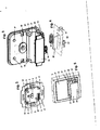
- the insert 3 has a support ring 4 and a front cover covering the UP cap 5, which centrally a bore pocket 6 for receiving a nut (see paragraph 7 in Fig. 2 ), at its upper portion two eckmann arranged receiving bolts 8 and at its lower portion a recess for the passage a plug-in device 9 has.
- UP-cap 5 and support ring 4 are firmly connected. The attachment of the UP-cap 5 on the support ring 4 on the one hand by means of locking 11 in the lower portion and on the other hand by entanglement / caulking in the upper portion respectively at the corners, including a web 10 is introduced in the support ring 4.
- the base plate having a holder 15 has in its lower portion a cross-sectionally U-shaped holding device for a mobile audio device, consisting of a front plate 16, a parallel thereto arranged counter-plate 17 and connecting these two plates bottom plate 26.
- a cross-sectionally U-shaped holding device for a mobile audio device consisting of a front plate 16, a parallel thereto arranged counter-plate 17 and connecting these two plates bottom plate 26.
- guide profiles 18 may be introduced into the upper edges of the counter-plate 17.
- the base plate of the holder 15 has centrally a receptacle 19, through the bore of which a screwed connection with the nut (see paragraph 7 in FIG Fig. 2 ) serving screw 20 can grip.
- the base plate of the holder 15 has in its upper portion two corners arranged on the corner 21 for engagement of the receiving bolt 8 of the UP-cap 5.
- the central plate 27 having a base plate has in its lower portion a recess 30 which is suitable for reaching through the U-shaped holding device of the holder 15 with front plate 16, counter plate 17 and bottom plate 26.
- optionally inserted guide webs 31 can serve for engagement with the optional guide profiles 18 of the counterplate 17 of the holder 15 in the upper corners of the recess 30.
- this recess 30 is closed off by means of a front plate 28, which is expediently provided with an IR window 29 (area permeable to infrared radiation) and is connected to the base plate of the central plate 27 via lateral and possibly also bottom-side wall sections 32.
- the central disk 27 may be provided with a bore 33, via which the accessibility of a connection socket (see paragraph 14 in the FIGS. 3 and 4 ) given is.
- screw 20 As screw 20, a standard screw or optionally a screw with drive in special form for increased theft protection can be used.
- Fig. 3 is a perspective view of a holder 15 is shown, wherein in addition to the above-described structural components, such as front panel 16, back plate 17 with optional guide profiles 18, bottom plate 26, receptacle 19 and the two holes 21 and two components one at the bottom of Bottom plate 26 mounted circuit board (see paragraph 22 in Fig. 4 ), namely a line-in input port 14 (for jack) and an IR receiver 23.
- a line-in input port 14 for jack
- an IR receiver 23 receives control signals of an IR remote control, which serve, for example, for setting the desired volume or the desired sound image or a desired music title.
- an LED arranged next to the IR receiver 23 flashes when the remote control is operated.
- FIG. 4 is a perspective view of the Fig. 3 already mentioned circuit board 22 shown.
- This circuit board 22 allows on the one hand by means of a plug-in device 25, the electrical connection of a mobile audio device and on the other hand, the electrical connection with the flush-mounted insert 3 by means of a plug device 24.
- the plug device 25 engages through a recess, not shown in the bottom plate 26 of the holder 15th Question die Plug-in device 24, the electrical connection between the IR receiver 23 and LED and the UP insert 3 is additionally ensured.
- the electrical connection between the connection socket 14 and the mobile audio device is ensured via the plug-in device 25.
- FIG. 5 is a perspective view of a flush-mounted installation device 1 with charger for a mobile audio device shown. It can be seen in particular that the assembly formed from flush-mounted insert 3 with mounted holder 15 is essentially covered by the central disk 27 and the cover frame 13. The cover frame 13 is locked by the mounted holder 15 (see Fig. 1 ). The central disk 27 is fixed by latching means on the UP-cap 5. The front panel 28 of the central disk 27 covers the front panel 16 of the holder 15, the IR window 29 is disposed directly above the IR receiver 23. The connection socket 14 is arranged directly behind the bore 33. It is to recognize the suitable for the reception of a mobile audio device, designed in cross-section U-shaped holding device consisting of counter-plate 17, bottom plate 23 (with the plug device 25) and the front panels 28/16.
- central disk 27 z. B molded plastic detent springs which engage in locking webs of the holder 15.
- the central disk 27 z. B. also metal detent springs which engage over edges of the UP insert 3.
- FIGS. 6 and 7 are two a mobile audio device carrying electrical flush-mounted installation devices of different designs shown. It can be seen in particular that a shapely integration / integration of the electrical flush-mounted installation device 1 in an installation device flush-mounted program respectively switch and socket flush-mounted program and a combination with other devices, such as switches / buttons / dimmers / sockets, this switch and socket flush-mounted program is possible.
- the shown mobile audio device 34 fits into both of the illustrated flush-mounted installation devices 1.
- the cover frame 13 and the central discs 27 including front panels 28 each designed differently, while one and the same UP insert 3 and a and the same holder 14 including printed circuit board 22 for the various flush-mounted programs is used.
Abstract
Description
- Die Erfindung betrifft ein elektrisches Unterputz-Installationsgerät für ein mobiles Audiogerät.
- Soll ein elektrisches Unterputz-Installationsgerät geschaffen werden, welches zur Aufladung der Akkumulatoren eines mobilen Audiogerätes dienen soll, besteht prinzipiell das Problem, dass das Unterputz-Installationsgerät zur Aufnahme des Audiogerätes relativ weit aus der Wand heraus und in den Raum hineinragt. Hierdurch ergibt sich einerseits die Gefahr, dass Personen verletzt werden, andererseits ist dies insbesondere auch beim Renovieren, wie Tapezieren, von Nachteil.
- Der Erfindung liegt die Aufgabe zugrunde, ein auch bei Renovierungsarbeiten unproblematisches elektrisches Unterputz-Installationsgerät für ein mobiles Audiogerät anzugeben.
- Diese Aufgabe wird erfindungsgemäß gelöst durch ein elektrisches Unterputz-Installationsgerät zur Aufnahme eines mobilen Audiogeräts,
- mit einem ein Ladegerät, einen elektrischen 230V-Anschluss, optional einen Audioverstärker und optional einen Anschluss für Lautsprecher beinhaltenden UP-Einsatz, welcher einen Tragring und eine damit verbundene, die Frontseite bedeckende UP-Kappe aufweist, welche an ihrem oberen Abschnitt mit mindestens einem Aufnahmebolzen versehen ist und welche eine Ausnehmung zum Durchgriff einer ersten Steckvorrichtung aufweist,
- mit einem Halter, welcher in seinem oberen Abschnitt mit mindestens einer Bohrung zum Eingriff des Aufnahmebolzens versehen ist und welcher eine im Querschnitt U-förmig ausgebildete Haltevorrichtung für das mobile Audiogerät aufweist, bestehend aus einer Frontplatte, einer hierzu parallel angeordneten Gegenplatte und einer diese beiden Platten verbindenden Bodenplatte, an deren Unterseite eine Leiterplatte montiert ist,
- mit einer Zentralscheibe, welche eine Ausnehmung aufweist, die zum Durchgreifen der Haltevorrichtung des Halters geeignet ist
- und mit einem Abdeckrahmen,
- wobei die Leiterplatte einerseits mittels einer zweiten Steckvorrichtung den elektrischen Anschluss des mobilen Audiogerätes und andererseits mittels einer dritten Steckvorrichtung die elektrische Verbindung mit dem UP-Einsatz via erster Steckvorrichtung ermöglicht.
- Die mit der Erfindung erzielbaren Vorteile bestehen insbesondere darin, dass die Zentralscheibe sowie der Halter vor der Durchführung von Renovierungsmaßnahmen vom UP-Einsatz demontiert werden können. Damit ragt nur noch der mindestens eine, relativ kurze Aufnahmebolzen aus der Wand, während die relativ sperrige Haltevorrichtung für das mobile Audiogerät demontiert ist. Ein Tapezieren ist hierdurch ohne Behinderungen möglich. Insgesamt handelt es sich beim vorgeschlagenen Unterputz-Installationsgerät um ein sehr robustes und kompaktes Gerät, welches zudem material- und fertigungstechnisch optimiert ist.
- Wenn zusätzlich zum Ladegerät auch ein Audioverstärker und ein Anschluss für Lautsprecher im UP-Einsatz vorgesehen sind, ist eine Beschallung eines Raumes auch über externe Lautsprecher möglich, wobei eine Regelung der Lautstärke und des Klanges sowie eine Ansteuerung des im Unterputz-Installationsgerät aufgesetzten mobilen Audiogerätes mittels einer Fernbedienung via IR-Signale erfolgen kann. Zweckmäßige Ausgestaltungen der Erfindung sind in den Unteransprüchen gekennzeichnet.
- Die Erfindung wird nachstehend an Hand der in der Zeichnung dargestellten Ausführungsbeispiele näher erläutert. Es zeigen:
- Fig. 1
- alle Hauptkomponenten eines elektrisches Unterputz-Installationsgeräts mit Ladegerät für ein mobiles Audiogerät in Form einer Explosionsdarstellung,
- Fig. 2
- eine perspektivische Sicht auf die Frontseite eines UP-Einsatzes,
- Fig. 3
- eine perspektivische Ansicht eines Halters,
- Fig. 4
- eine perspektivische Ansicht einer Leiterplatte,
- Fig. 5
- eine perspektivische Ansicht eines elektrisches Unterputz-Installationsgeräts mit Ladegerät für ein mobiles Audiogerät,
- Fig. 6,7
- zwei ein mobiles Audiogerät tragende elektrische Unterputz-Installationsgeräte unterschiedlichen Designs.
- In
Fig. 1 sind alle Hauptkomponenten eines elektrischen Unterputz-Installationsgeräts mit Ladegerät für ein mobiles Audiogerät in Form einer Explosionsdarstellung gezeigt. Das elektrische Unterputz-Installationsgerät 1 weist als Hauptkomponenten einen zum Einbau in eine handelsübliche 60mm-UP-Gerätedose nach DIN 49073 geeigneten UP-Einsatz 3 (Unterputz-Einsatz), einen Abdeckrahmen 13, einen Halter 15 und eine Zentralscheibe 27 auf. - Der Einsatz 3 besitzt einen Tragring 4 und eine die Frontseite bedeckende UP-Kappe 5, welche mittig eine mit Bohrung versehene Tasche 6 zur Aufnahme einer Mutter (siehe Ziffer 7 in
Fig. 2 ), an ihrem oberen Abschnitt zwei eckseitig angeordnete Aufnahmebolzen 8 und an ihrem unteren Abschnitt eine Ausnehmung zum Durchgriff einer Steckvorrichtung 9 aufweist. UP-Kappe 5 und Tragring 4 sind fest miteinander verbunden. Die Befestigung der UP-Kappe 5 am Tragring 4 erfolgt einerseits mittels Verrastungen 11 im unteren Abschnitt sowie andererseits durch eine Verschränkung/Verstemmung im oberen Abschnitt respektive an dessen Ecken, wozu jeweils ein Steg 10 im Tragring 4 eingebracht ist. - Der eine Basisplatte aufweisende Halter 15 weist in seinem unteren Abschnitt eine im Querschnitt U-förmig ausgebildete Haltevorrichtung für ein mobiles Audiogerät auf, bestehend aus einer Frontplatte 16, einer parallel hierzu angeordneten Gegenplatte 17 und einer diese beiden Platten verbindenden Bodenplatte 26. Um ein präzises Aufschieben der Zentralscheibe 27 auf den Halter 15 zu erleichtern, können optional Führungsprofile 18 in den oberen Kanten der Gegenplatte 17 eingebracht sein. Die Basisplatte des Halters 15 weist mittig eine Aufnahme 19 auf, durch deren Bohrung eine zur Verschraubung mit der Mutter (siehe Ziffer 7 in
Fig. 2 ) dienende Schraube 20 greifen kann. Die Basisplatte des Halters 15 weist in ihrem oberen Abschnitt zwei eckseitig angeordnete Bohrungen 21 zum Eingriff der Aufnahmebolzen 8 der UP-Kappe 5 auf. - Die eine Basisplatte aufweisende Zentralscheibe 27 weist in ihrem unteren Abschnitt eine Ausnehmung 30 auf, welche zum Durchgreifen der U-förmig ausgebildeten Haltevorrichtung des Halters 15 mit Frontplatte 16, Gegenplatte 17 und Bodenplatte 26 geeignet ist. Dabei können in den oberen Ecken der Ausnehmung 30 optional eingebrachte Führungsstege 31 für den Eingriff mit den optionalen Führungsprofilen 18 der Gegenplatte 17 des Halters 15 dienen. Frontseitig wird diese Ausnehmung 30 mittels einer Frontplatte 28 abgeschlossen, welche zweckmäßig mit einem IR-Fenster 29 (für Infrarotstrahlung durchlässiger Bereich) versehen ist und über seitliche und gegebenenfalls auch bodenseitige Wandabschnitte 32 mit der Basisplatte der Zentralscheibe 27 verbunden ist. Die Zentralscheibe 27 kann mit einer Bohrung 33 versehen sein, über welche die Zugänglichkeit einer Anschlussbuchse (siehe Ziffer 14 in den
Figuren 3 und 4 ) gegeben ist. - In
Fig. 2 ist eine perspektivische Sicht auf die Frontseite eines UP-Einsatzes dargestellt. Der UP-Einsatz 3 weist einen elektrischen 230V-Anschluss, einen Anschluss für Lautsprecher, ein Ladegerät und einen Audioverstärker auf. Über die durch die UP-Kappe 5 greifende Steckvorrichtung 9 kann (via Leiterplatte 22, sieheFig. 4 ) eine elektrische Verbindung mit einem mobilen Audiogerät (siehe Ziffer 34 in denFiguren 6 und 7 ) hergestellt werden, um hierdurch - eine Aufladung des Akkumulators des mobilen Audiogerätes zu bewirken und/oder
- um vom mobilen Audiogerät abgegebene Audiosignale zu verstärken und diese wunschgemäß verstärkten Audiosignale an externe Lautsprecher abgeben zu können.
- Von großer Wichtigkeit ist die robuste und verdrehsichere Aufnahme des eingesteckten mobilen Audiogerätes, wozu insbesondere die folgenden Maßnahmen beitragen:
- die in die Bohrungen 21 des Halters 15 eingreifenden Aufnahmebolzen 8 dienen zur Positionierung und Kraftübertragung und unterbinden insbesondere jedes Verdrehen / Verrutschen des Halters 15 respektive der Zentralscheibe 27 gegenüber dem UP-Einsatz 3,
- die in die Gewindebohrung der in der Tasche 6 befindlichen Mutter 7 eingedrehte Schraube 20 stellt eine sichere und mechanisch robuste Verankerung des Halters 15 mit Abdeckrahmen 13 am UP-Einsatz 5 sicher und dient zur Fixierung / Diebstahlsicherung / Kraftübertragung,
- die Verrastungen 11 einerseits sowie die Verstemmungen unter Zuhilfenahme von Stegen 10 andererseits garantieren eine dauerhaft sichere Verbindung zwischen Tragplatte 4 und UP-Kappe 5,
- eine sichere Montage des UP-Einsatzes 5 in handelsüblichen 60mm-Unterputzdosen aus Kunststoff erfolgt in üblicher Weise mittels (nicht dargestellter) Federspreizen oder mittels durch Bohrungen im Tragring 4 greifender Montageschrauben.
- Als Schraube 20 kann eine Standardschraube oder optional eine Schraube mit Antrieb in Sonderform für erhöhten Diebstahlschutz verwendet werden.
- In
Fig. 3 ist eine perspektivische Ansicht eines Halters 15 dargestellt, wobei außer den vorstehend bereits erläuterten konstruktiven Komponenten, wie Frontplatte 16, Gegenplatte 17 mit optionalen Führungsprofilen 18, Bodenplatte 26, Aufnahme 19 und den beiden Bohrungen 21 auch zwei Komponenten einer an der Unterseite der Bodenplatte 26 montierten Leiterplatte (siehe Ziffer 22 inFig. 4 ) zu erkennen sind, nämlich eine einen Line-In-Eingang darstellende Anschlussbuchse 14 (für Klinkenstecker) und ein IR-Empfänger 23. An die Anschlussbuchse 14 kann eine externe Audio-Anlage angeschlossen werden. Der IR-Empfänger 23 empfängt Ansteuersignale einer IR-Fernbedienung, welche beispielsweise zur Einstellung der gewünschten Lautstärke oder des gewünschten Klangbildes oder eines gewünschten Musiktitels dienen. eine neben dem IR-Empfänger 23 angeordnete LED blinkt bei Betätigung der Fernbedienung. - In
Fig. 4 ist eine perspektivische Ansicht der unterFig. 3 bereits erwähnten Leiterplatte 22 dargestellt. Diese Leiterplatte 22 ermöglicht einerseits mittels einer Steckvorrichtung 25 den elektrischen Anschluss eines mobilen Audiogerätes und andererseits die elektrische Verbindung mit dem UP-Einsatz 3 mittels einer Steckvorrichtung 24. Die Steckvorrichtung 25 greift durch eine nicht dargestellte Ausnehmung in der Bodenplatte 26 des Halters 15. Über die Steckvorrichtung 24 wird zusätzlich die elektrische Verbindung zwischen dem IR-Empfänger 23 sowie LED und dem UP-Einsatz 3 sichergestellt. Über die Steckvorrichtung 25 wird zusätzlich die elektrische Verbindung zwischen der Anschlussbuchse 14 und dem mobilen Audiogerät gewährleistet. - In
Fig. 5 ist eine perspektivische Ansicht eines elektrischen Unterputz-Installationsgeräts 1 mit Ladegerät für ein mobiles Audiogerät dargestellt. Es ist insbesondere zu erkennen, dass die aus UP-Einsatz 3 mit montiertem Halter 15 gebildete Baueinheit im Wesentlichen durch die Zentralscheibe 27 und den Abdeckrahmen 13 abgedeckt ist. Der Abdeckrahmen 13 wird durch den montierten Halter 15 arretiert (sieheFig. 1 ). Die Zentralscheibe 27 ist durch Rastmittel an der UP-Kappe 5 befestigt. Die Frontplatte 28 der Zentralscheibe 27 deckt die Frontplatte 16 des Halters 15 ab, das IR-Fenster 29 ist direkt über dem IR-Empfänger 23 angeordnet. Die Anschlussbuchse 14 ist unmittelbar hinter der Bohrung 33 angeordnet. Es ist die für die Aufnahme eines mobilen Audiogeräts geeignete, im Querschnitt U-förmig ausgebildete Haltevorrichtung zu erkennen, bestehend aus Gegenplatte 17, Bodenplatte 23 (mit der Steckvorrichtung 25) und den Frontplatten 28/16. - Zur Verrastung kann die Zentralscheibe 27 z. B. angespritzte Kunststoff-Rastfedem aufweisen, welche in Raststege des Halters 15 eingreifen. Alternativ kann die Zentralscheibe 27 z. B. auch Metall-Rastfedern aufweisen, welche über Kanten des UP-Einsatzes 3 einrasten.
- In den
Figuren 6 und 7 sind zwei ein mobiles Audiogerät tragende elektrische Unterputz-Installationsgeräte unterschiedlichen Designs dargestellt. Dabei ist insbesondere zu erkennen, dass eine formschöne Einbindung/Integration des elektrischen Unterputz-Installationsgeräts 1 in ein Installationsgeräte-Unterputz-Programm respektive Schalter- und Steckdosen-Unterputz-Programm sowie eine Kombination mit weiteren Geräten, beispielsweise Schaltern / Tastern / Dimmern / Steckdosen, dieses Schalter- und Steckdosen-Unterputz-Programms möglich ist. Das gezeigte mobile Audiogerät 34 passt in beide der dargestellten Unterputz-Installationsgeräte 1. Gemäß den typischen Merkmalen eines Installationsgeräte-Unterputz-Programms sind die Abdeckrahmen 13 sowie die Zentralscheiben 27 inklusive Frontplatten 28 jeweils unterschiedlich gestaltet, während ein und derselbe UP-Einsatz 3 und ein und derselbe Halter 14 inklusive Leiterplatte 22 für die verschiedenen Unterputz-Programme zum Einsatz gelangt. -
- 1
- elektrisches Unterputz-Installationsgerät zur Aufnahme eines mobilen Audiogeräts 34
- 2
- -
- 3
- UP-Einsatz inklusive elektrischem 230V-Anschluss, Anschluss für Lautsprecher, Ladegerät und Audioverstärker
- 4
- Tragring
- 5
- UP-Kappe
- 6
- Tasche in der UP-Kappe 5 für Mutter 7
- 7
- Mutter
- 8
- Aufnahmebolzen
- 9
- Steckvorrichtung zur Verbindung mit der Leiterplatte 22
- 10
- Steg zum Verstemmung der UP-Kappe 5 auf dem Tragring 4
- 11
- Verrastung zwischen Tragring 4 / UP-Kappe 5
- 12
- -
- 13
- Abdeckrahmen
- 14
- Anschlussbuchse
- 15
- Halter
- 16
- Frontplatte
- 17
- Gegenplatte
- 18
- Führungsprofile
- 19
- Aufnahme für Schraube 20
- 20
- Schraube
- 21
- Bohrungen für Aufnahmebolzen 8
- 22
- Leiterplatte
- 23
- IR-Empfänger
- 24
- Steckvorrichtung für die Verbindung mit dem UP-Einsatz 3
- 25
- Steckvorrichtung für die Verbindung mit dem mobilen Audiogerät 34
- 26
- Bodenplatte
- 27
- Zentralscheibe
- 28
- Frontplatte
- 29
- IR-Fenster
- 30
- Ausnehmung
- 31
- Führungsstege
- 32
- Wandabschnitte
- 33
- Bohrung für Anschlussbuchse 14
- 34
- mobiles Audiogerät
Claims (5)
- Elektrisches Unterputz-Installationsgerät (1) zur Aufnahme eines mobilen Audiogeräts (34),• mit einem ein Ladegerät, einen elektrischen 230V-Anschluss, optional einen Audioverstärker und optional einen Anschluss für Lautsprecher beinhaltenden UP-Einsatz (3), welcher einen Tragring (4) und eine damit verbundene, die Frontseite bedeckende UP-Kappe (5) aufweist, welche an ihrem oberen Abschnitt mit mindestens einem Aufnahmebolzen (8) versehen ist und welche eine Ausnehmung zum Durchgriff einer ersten Steckvorrichtung (9) aufweist,• mit einem Halter (15), welcher in seinem oberen Abschnitt mit mindestens einer Bohrung (21) zum Eingriff des Aufnahmebolzens (8) versehen ist und welcher eine im Querschnitt U-förmig ausgebildete Haltevorrichtung für das mobile Audiogerät (34) aufweist, bestehend aus einer Frontplatte (16), einer hierzu parallel angeordneten Gegenplatte (17) und einer diese beiden Platten (16, 17) verbindenden Bodenplatte (26), an deren Unterseite eine Leiterplatte (22) montiert ist,• mit einer Zentralscheibe (27), welche eine Ausnehmung (30) aufweist, die zum Durchgreifen der Haltevorrichtung des Halters (15) geeignet ist• und mit einem Abdeckrahmen (13),• wobei die Leiterplatte (22) einerseits mittels einer zweiten Steckvorrichtung (25) den elektrischen Anschluss des mobilen Audiogerätes (34) und andererseits mittels einer dritten Steckvorrichtung (24) die elektrische Verbindung mit dem UP-Einsatz (3) via erster Steckvorrichtung (9) ermöglicht.
- Elektrisches Unterputz-Installationsgerät (1) nach Anspruch 1, dadurch gekennzeichnet, dass der Halter (15) eine Aufnahme (19) aufweist, durch deren Bohrung eine zur Verschraubung mit einer Mutter (7) dienende Schraube (20) greift, wobei die Mutter (7) in einer mit Bohrung versehenen Tasche (6) der UP-Kappe (5) angeordnet ist.
- Elektrisches Unterputz-Installationsgerät (1) nach Anspruch 1 oder 2, dadurch gekennzeichnet, dass die feste Verbindung zwischen Tragring (4) und UP-Kappe (5) durch Verschränkung / Verstemmung erfolgt, wozu Stege (10) im Tragring (4) eingebracht sind.
- Elektrisches Unterputz-Installationsgerät (1) nach einem der vorstehenden Ansprüche, dadurch gekennzeichnet, dass die Ausnehmung (30) mittels einer Frontplatte (28) abgeschlossen ist, welche über seitliche und/ oder bodenseitige Wandabschnitte (32) mit der Zentralscheibe (27) verbunden ist.
- Elektrisches Unterputz-Installationsgerät (1) nach Anspruch 4, dadurch gekennzeichnet, dass die Frontplatte (28) mit einem IR-Fenster (29) versehen ist, hinter welchem ein auf der Leiterplatte (22) montierter IR-Empfänger (23) angeordnet ist.
Applications Claiming Priority (1)
| Application Number | Priority Date | Filing Date | Title |
|---|---|---|---|
| DE102010005394A DE102010005394A1 (de) | 2010-01-22 | 2010-01-22 | Elektrisches Unterputz-Installationsgerät für ein mobiles Audiogerät |
Publications (3)
| Publication Number | Publication Date |
|---|---|
| EP2348598A2 true EP2348598A2 (de) | 2011-07-27 |
| EP2348598A3 EP2348598A3 (de) | 2012-06-20 |
| EP2348598B1 EP2348598B1 (de) | 2018-10-24 |
Family
ID=43639154
Family Applications (1)
| Application Number | Title | Priority Date | Filing Date |
|---|---|---|---|
| EP10014723.0A Not-in-force EP2348598B1 (de) | 2010-01-22 | 2010-11-18 | Elektrisches Unterputz-Installationsgerät für ein mobiles Audiogerät |
Country Status (4)
| Country | Link |
|---|---|
| EP (1) | EP2348598B1 (de) |
| CN (1) | CN102170100B (de) |
| DE (1) | DE102010005394A1 (de) |
| HK (1) | HK1157944A1 (de) |
Cited By (2)
| Publication number | Priority date | Publication date | Assignee | Title |
|---|---|---|---|---|
| US10139790B2 (en) | 2015-06-10 | 2018-11-27 | Vivint, Inc. | Powered faceplate integration |
| EP4243227A1 (de) * | 2022-03-07 | 2023-09-13 | Insta GmbH | Elektrisches/elektronisches installationsgerät, verfahren und verwendung zur parametrierung eines solchen installationsgerätes |
Families Citing this family (1)
| Publication number | Priority date | Publication date | Assignee | Title |
|---|---|---|---|---|
| DE202014100984U1 (de) | 2014-03-05 | 2014-04-22 | Gira Giersiepen Gmbh & Co. Kg | Elektrisches Unterputz-Installationsgerät für die Herstellung einer Datenübertragungsverbindung zwischen einem mobilen Audiogerät und einem stationären Musikwiedergabegerät |
Family Cites Families (4)
| Publication number | Priority date | Publication date | Assignee | Title |
|---|---|---|---|---|
| ITMI981194A1 (it) * | 1998-05-29 | 1999-11-29 | Bticino Spa | Sistema di connessione di telefoni cellulari ad un impianto telefonico domestico |
| ITMI981195A1 (it) * | 1998-05-29 | 1999-11-29 | Bticino Spa | Gruppo di alimentazione e ricarica per apparecchi telefonici portatili in particolare per telefoni cellulari |
| US6518724B2 (en) * | 2000-08-02 | 2003-02-11 | Simple Devices | Wall switch device and power outlet device |
| TW525864U (en) * | 2001-10-03 | 2003-03-21 | Sheng-Shing Liau | Rapid assembly cellular phone charger |
-
2010
- 2010-01-22 DE DE102010005394A patent/DE102010005394A1/de not_active Withdrawn
- 2010-11-18 EP EP10014723.0A patent/EP2348598B1/de not_active Not-in-force
-
2011
- 2011-01-14 CN CN201110022260.5A patent/CN102170100B/zh not_active Expired - Fee Related
- 2011-11-11 HK HK11112241.9A patent/HK1157944A1/zh not_active IP Right Cessation
Non-Patent Citations (1)
| Title |
|---|
| None |
Cited By (3)
| Publication number | Priority date | Publication date | Assignee | Title |
|---|---|---|---|---|
| US10139790B2 (en) | 2015-06-10 | 2018-11-27 | Vivint, Inc. | Powered faceplate integration |
| US10591881B1 (en) | 2015-06-10 | 2020-03-17 | Vivint, Inc. | Powered faceplate integration |
| EP4243227A1 (de) * | 2022-03-07 | 2023-09-13 | Insta GmbH | Elektrisches/elektronisches installationsgerät, verfahren und verwendung zur parametrierung eines solchen installationsgerätes |
Also Published As
| Publication number | Publication date |
|---|---|
| HK1157944A1 (zh) | 2012-07-06 |
| EP2348598A3 (de) | 2012-06-20 |
| EP2348598B1 (de) | 2018-10-24 |
| DE102010005394A1 (de) | 2011-07-28 |
| CN102170100B (zh) | 2016-01-20 |
| CN102170100A (zh) | 2011-08-31 |
Similar Documents
| Publication | Publication Date | Title |
|---|---|---|
| DE60108533T2 (de) | Adapter zur befestigung einer frontplatte erster art auf einem elektrischen steckdosenhohlraum zweiter art | |
| DE102014227053B4 (de) | Lautsprecherboxenanordnung und Lautsprecherbox | |
| DE102011053341B4 (de) | Elektrisches/elektronisches Gerät | |
| EP2360810A2 (de) | Elektrisches Unterputz-Installationsgerät zur Aufnahme eines mobilen Audio- und Kommunikationsgerätes | |
| EP2093852A1 (de) | Unterputzradio | |
| EP2348598B1 (de) | Elektrisches Unterputz-Installationsgerät für ein mobiles Audiogerät | |
| EP3203351A1 (de) | Kabelhalter, kabelhaltersystem und gerätehaltersystem | |
| DE102012103145A1 (de) | Unterputz-Installationsvorrichtung für elektronische Geräte | |
| DE102004016539B4 (de) | Elektro-Installationsgerät zur Wandmontage | |
| EP0987922A2 (de) | Multiresonanzplatte | |
| EP2905524B1 (de) | Haltevorrichtung zum Halten eines elektronischen Gerätes an einer Wand | |
| DE202005015757U1 (de) | Haltevorrichtung und Set zur Halterung eines transportablen elektronischen Gerätes | |
| EP2897375B1 (de) | Möbelstück mit einem Einbauverstärker | |
| CH695715A5 (de) | Apparat für elektrische Hausinstallationen. | |
| EP2438836B1 (de) | Anordnung mindestens einer Leichtbauplatte an einer mit einer Stromversorgung ausgestatteten Trägerplatte und Leichtbaumöbel | |
| EP1422800B1 (de) | Geräteträger zur Befestigung von Geräten auf eine aussen oder innen isolierte Gebäudefassade oder Gebäudemauer | |
| DE202007000791U1 (de) | Unterputz-Montageeinheit | |
| DE102013106411A1 (de) | Lampenbefestigungssystem | |
| DE202011050749U1 (de) | Möbel | |
| CH704609B1 (de) | Halterung für elektrische Geräte. | |
| EP2293399A2 (de) | Unterputz-Steckdose | |
| DE102010037344A1 (de) | Halterung für elektronische Geräte | |
| DE202013103674U1 (de) | Lautsprecher-Modulsystem | |
| DE202010016460U1 (de) | Mediengeräte | |
| DE102018000389B4 (de) | Einbausystem |
Legal Events
| Date | Code | Title | Description |
|---|---|---|---|
| PUAI | Public reference made under article 153(3) epc to a published international application that has entered the european phase |
Free format text: ORIGINAL CODE: 0009012 |
|
| AK | Designated contracting states |
Kind code of ref document: A2 Designated state(s): AL AT BE BG CH CY CZ DE DK EE ES FI FR GB GR HR HU IE IS IT LI LT LU LV MC MK MT NL NO PL PT RO RS SE SI SK SM TR |
|
| AX | Request for extension of the european patent |
Extension state: BA ME |
|
| PUAL | Search report despatched |
Free format text: ORIGINAL CODE: 0009013 |
|
| AK | Designated contracting states |
Kind code of ref document: A3 Designated state(s): AL AT BE BG CH CY CZ DE DK EE ES FI FR GB GR HR HU IE IS IT LI LT LU LV MC MK MT NL NO PL PT RO RS SE SI SK SM TR |
|
| AX | Request for extension of the european patent |
Extension state: BA ME |
|
| RIC1 | Information provided on ipc code assigned before grant |
Ipc: H02G 3/12 20060101ALI20120514BHEP Ipc: H02J 7/00 20060101AFI20120514BHEP Ipc: H01R 13/66 20060101ALI20120514BHEP |
|
| 17P | Request for examination filed |
Effective date: 20121204 |
|
| 17Q | First examination report despatched |
Effective date: 20151222 |
|
| GRAP | Despatch of communication of intention to grant a patent |
Free format text: ORIGINAL CODE: EPIDOSNIGR1 |
|
| INTG | Intention to grant announced |
Effective date: 20180524 |
|
| GRAS | Grant fee paid |
Free format text: ORIGINAL CODE: EPIDOSNIGR3 |
|
| GRAA | (expected) grant |
Free format text: ORIGINAL CODE: 0009210 |
|
| AK | Designated contracting states |
Kind code of ref document: B1 Designated state(s): AL AT BE BG CH CY CZ DE DK EE ES FI FR GB GR HR HU IE IS IT LI LT LU LV MC MK MT NL NO PL PT RO RS SE SI SK SM TR |
|
| REG | Reference to a national code |
Ref country code: GB Ref legal event code: FG4D Free format text: NOT ENGLISH |
|
| REG | Reference to a national code |
Ref country code: CH Ref legal event code: EP |
|
| REG | Reference to a national code |
Ref country code: IE Ref legal event code: FG4D Free format text: LANGUAGE OF EP DOCUMENT: GERMAN |
|
| REG | Reference to a national code |
Ref country code: AT Ref legal event code: REF Ref document number: 1057815 Country of ref document: AT Kind code of ref document: T Effective date: 20181115 |
|
| REG | Reference to a national code |
Ref country code: DE Ref legal event code: R096 Ref document number: 502010015481 Country of ref document: DE |
|
| PGFP | Annual fee paid to national office [announced via postgrant information from national office to epo] |
Ref country code: NL Payment date: 20181120 Year of fee payment: 9 |
|
| PGFP | Annual fee paid to national office [announced via postgrant information from national office to epo] |
Ref country code: AT Payment date: 20181121 Year of fee payment: 9 Ref country code: DE Payment date: 20181120 Year of fee payment: 9 |
|
| REG | Reference to a national code |
Ref country code: NL Ref legal event code: FP |
|
| REG | Reference to a national code |
Ref country code: LT Ref legal event code: MG4D |
|
| PG25 | Lapsed in a contracting state [announced via postgrant information from national office to epo] |
Ref country code: LV Free format text: LAPSE BECAUSE OF FAILURE TO SUBMIT A TRANSLATION OF THE DESCRIPTION OR TO PAY THE FEE WITHIN THE PRESCRIBED TIME-LIMIT Effective date: 20181024 Ref country code: ES Free format text: LAPSE BECAUSE OF FAILURE TO SUBMIT A TRANSLATION OF THE DESCRIPTION OR TO PAY THE FEE WITHIN THE PRESCRIBED TIME-LIMIT Effective date: 20181024 Ref country code: LT Free format text: LAPSE BECAUSE OF FAILURE TO SUBMIT A TRANSLATION OF THE DESCRIPTION OR TO PAY THE FEE WITHIN THE PRESCRIBED TIME-LIMIT Effective date: 20181024 Ref country code: BG Free format text: LAPSE BECAUSE OF FAILURE TO SUBMIT A TRANSLATION OF THE DESCRIPTION OR TO PAY THE FEE WITHIN THE PRESCRIBED TIME-LIMIT Effective date: 20190124 Ref country code: HR Free format text: LAPSE BECAUSE OF FAILURE TO SUBMIT A TRANSLATION OF THE DESCRIPTION OR TO PAY THE FEE WITHIN THE PRESCRIBED TIME-LIMIT Effective date: 20181024 Ref country code: PL Free format text: LAPSE BECAUSE OF FAILURE TO SUBMIT A TRANSLATION OF THE DESCRIPTION OR TO PAY THE FEE WITHIN THE PRESCRIBED TIME-LIMIT Effective date: 20181024 Ref country code: IS Free format text: LAPSE BECAUSE OF FAILURE TO SUBMIT A TRANSLATION OF THE DESCRIPTION OR TO PAY THE FEE WITHIN THE PRESCRIBED TIME-LIMIT Effective date: 20190224 Ref country code: FI Free format text: LAPSE BECAUSE OF FAILURE TO SUBMIT A TRANSLATION OF THE DESCRIPTION OR TO PAY THE FEE WITHIN THE PRESCRIBED TIME-LIMIT Effective date: 20181024 Ref country code: NO Free format text: LAPSE BECAUSE OF FAILURE TO SUBMIT A TRANSLATION OF THE DESCRIPTION OR TO PAY THE FEE WITHIN THE PRESCRIBED TIME-LIMIT Effective date: 20190124 |
|
| PG25 | Lapsed in a contracting state [announced via postgrant information from national office to epo] |
Ref country code: RS Free format text: LAPSE BECAUSE OF FAILURE TO SUBMIT A TRANSLATION OF THE DESCRIPTION OR TO PAY THE FEE WITHIN THE PRESCRIBED TIME-LIMIT Effective date: 20181024 Ref country code: GR Free format text: LAPSE BECAUSE OF FAILURE TO SUBMIT A TRANSLATION OF THE DESCRIPTION OR TO PAY THE FEE WITHIN THE PRESCRIBED TIME-LIMIT Effective date: 20190125 Ref country code: SE Free format text: LAPSE BECAUSE OF FAILURE TO SUBMIT A TRANSLATION OF THE DESCRIPTION OR TO PAY THE FEE WITHIN THE PRESCRIBED TIME-LIMIT Effective date: 20181024 Ref country code: AL Free format text: LAPSE BECAUSE OF FAILURE TO SUBMIT A TRANSLATION OF THE DESCRIPTION OR TO PAY THE FEE WITHIN THE PRESCRIBED TIME-LIMIT Effective date: 20181024 Ref country code: PT Free format text: LAPSE BECAUSE OF FAILURE TO SUBMIT A TRANSLATION OF THE DESCRIPTION OR TO PAY THE FEE WITHIN THE PRESCRIBED TIME-LIMIT Effective date: 20190224 |
|
| REG | Reference to a national code |
Ref country code: CH Ref legal event code: PL |
|
| REG | Reference to a national code |
Ref country code: DE Ref legal event code: R097 Ref document number: 502010015481 Country of ref document: DE |
|
| PG25 | Lapsed in a contracting state [announced via postgrant information from national office to epo] |
Ref country code: DK Free format text: LAPSE BECAUSE OF FAILURE TO SUBMIT A TRANSLATION OF THE DESCRIPTION OR TO PAY THE FEE WITHIN THE PRESCRIBED TIME-LIMIT Effective date: 20181024 Ref country code: LU Free format text: LAPSE BECAUSE OF NON-PAYMENT OF DUE FEES Effective date: 20181118 Ref country code: IT Free format text: LAPSE BECAUSE OF FAILURE TO SUBMIT A TRANSLATION OF THE DESCRIPTION OR TO PAY THE FEE WITHIN THE PRESCRIBED TIME-LIMIT Effective date: 20181024 Ref country code: CZ Free format text: LAPSE BECAUSE OF FAILURE TO SUBMIT A TRANSLATION OF THE DESCRIPTION OR TO PAY THE FEE WITHIN THE PRESCRIBED TIME-LIMIT Effective date: 20181024 |
|
| REG | Reference to a national code |
Ref country code: BE Ref legal event code: MM Effective date: 20181130 |
|
| REG | Reference to a national code |
Ref country code: IE Ref legal event code: MM4A |
|
| PG25 | Lapsed in a contracting state [announced via postgrant information from national office to epo] |
Ref country code: RO Free format text: LAPSE BECAUSE OF FAILURE TO SUBMIT A TRANSLATION OF THE DESCRIPTION OR TO PAY THE FEE WITHIN THE PRESCRIBED TIME-LIMIT Effective date: 20181024 Ref country code: SK Free format text: LAPSE BECAUSE OF FAILURE TO SUBMIT A TRANSLATION OF THE DESCRIPTION OR TO PAY THE FEE WITHIN THE PRESCRIBED TIME-LIMIT Effective date: 20181024 Ref country code: CH Free format text: LAPSE BECAUSE OF NON-PAYMENT OF DUE FEES Effective date: 20181130 Ref country code: MC Free format text: LAPSE BECAUSE OF FAILURE TO SUBMIT A TRANSLATION OF THE DESCRIPTION OR TO PAY THE FEE WITHIN THE PRESCRIBED TIME-LIMIT Effective date: 20181024 Ref country code: LI Free format text: LAPSE BECAUSE OF NON-PAYMENT OF DUE FEES Effective date: 20181130 Ref country code: SM Free format text: LAPSE BECAUSE OF FAILURE TO SUBMIT A TRANSLATION OF THE DESCRIPTION OR TO PAY THE FEE WITHIN THE PRESCRIBED TIME-LIMIT Effective date: 20181024 Ref country code: EE Free format text: LAPSE BECAUSE OF FAILURE TO SUBMIT A TRANSLATION OF THE DESCRIPTION OR TO PAY THE FEE WITHIN THE PRESCRIBED TIME-LIMIT Effective date: 20181024 |
|
| PLBE | No opposition filed within time limit |
Free format text: ORIGINAL CODE: 0009261 |
|
| STAA | Information on the status of an ep patent application or granted ep patent |
Free format text: STATUS: NO OPPOSITION FILED WITHIN TIME LIMIT |
|
| RAP2 | Party data changed (patent owner data changed or rights of a patent transferred) |
Owner name: ABB SCHWEIZ AG |
|
| GBPC | Gb: european patent ceased through non-payment of renewal fee |
Effective date: 20190124 |
|
| 26N | No opposition filed |
Effective date: 20190725 |
|
| PG25 | Lapsed in a contracting state [announced via postgrant information from national office to epo] |
Ref country code: SI Free format text: LAPSE BECAUSE OF FAILURE TO SUBMIT A TRANSLATION OF THE DESCRIPTION OR TO PAY THE FEE WITHIN THE PRESCRIBED TIME-LIMIT Effective date: 20181024 Ref country code: IE Free format text: LAPSE BECAUSE OF NON-PAYMENT OF DUE FEES Effective date: 20181118 Ref country code: FR Free format text: LAPSE BECAUSE OF NON-PAYMENT OF DUE FEES Effective date: 20181224 |
|
| PG25 | Lapsed in a contracting state [announced via postgrant information from national office to epo] |
Ref country code: BE Free format text: LAPSE BECAUSE OF NON-PAYMENT OF DUE FEES Effective date: 20181130 |
|
| PG25 | Lapsed in a contracting state [announced via postgrant information from national office to epo] |
Ref country code: GB Free format text: LAPSE BECAUSE OF NON-PAYMENT OF DUE FEES Effective date: 20190124 |
|
| PG25 | Lapsed in a contracting state [announced via postgrant information from national office to epo] |
Ref country code: MT Free format text: LAPSE BECAUSE OF FAILURE TO SUBMIT A TRANSLATION OF THE DESCRIPTION OR TO PAY THE FEE WITHIN THE PRESCRIBED TIME-LIMIT Effective date: 20181024 |
|
| PG25 | Lapsed in a contracting state [announced via postgrant information from national office to epo] |
Ref country code: TR Free format text: LAPSE BECAUSE OF FAILURE TO SUBMIT A TRANSLATION OF THE DESCRIPTION OR TO PAY THE FEE WITHIN THE PRESCRIBED TIME-LIMIT Effective date: 20181024 |
|
| REG | Reference to a national code |
Ref country code: DE Ref legal event code: R119 Ref document number: 502010015481 Country of ref document: DE |
|
| PG25 | Lapsed in a contracting state [announced via postgrant information from national office to epo] |
Ref country code: CY Free format text: LAPSE BECAUSE OF FAILURE TO SUBMIT A TRANSLATION OF THE DESCRIPTION OR TO PAY THE FEE WITHIN THE PRESCRIBED TIME-LIMIT Effective date: 20181024 Ref country code: MK Free format text: LAPSE BECAUSE OF NON-PAYMENT OF DUE FEES Effective date: 20181024 Ref country code: HU Free format text: LAPSE BECAUSE OF FAILURE TO SUBMIT A TRANSLATION OF THE DESCRIPTION OR TO PAY THE FEE WITHIN THE PRESCRIBED TIME-LIMIT; INVALID AB INITIO Effective date: 20101118 |
|
| REG | Reference to a national code |
Ref country code: NL Ref legal event code: MM Effective date: 20191201 |
|
| REG | Reference to a national code |
Ref country code: AT Ref legal event code: MM01 Ref document number: 1057815 Country of ref document: AT Kind code of ref document: T Effective date: 20191118 |
|
| PG25 | Lapsed in a contracting state [announced via postgrant information from national office to epo] |
Ref country code: NL Free format text: LAPSE BECAUSE OF NON-PAYMENT OF DUE FEES Effective date: 20191201 |
|
| PG25 | Lapsed in a contracting state [announced via postgrant information from national office to epo] |
Ref country code: DE Free format text: LAPSE BECAUSE OF NON-PAYMENT OF DUE FEES Effective date: 20200603 |
|
| PG25 | Lapsed in a contracting state [announced via postgrant information from national office to epo] |
Ref country code: AT Free format text: LAPSE BECAUSE OF NON-PAYMENT OF DUE FEES Effective date: 20191118 |