EP2346028A1 - Vorrichtung und Verfahren zur Umwandlung eines ersten parametrisch beabstandeten Audiosignals in ein zweites parametrisch beabstandetes Audiosignal - Google Patents
Vorrichtung und Verfahren zur Umwandlung eines ersten parametrisch beabstandeten Audiosignals in ein zweites parametrisch beabstandetes Audiosignal Download PDFInfo
- Publication number
- EP2346028A1 EP2346028A1 EP10156263A EP10156263A EP2346028A1 EP 2346028 A1 EP2346028 A1 EP 2346028A1 EP 10156263 A EP10156263 A EP 10156263A EP 10156263 A EP10156263 A EP 10156263A EP 2346028 A1 EP2346028 A1 EP 2346028A1
- Authority
- EP
- European Patent Office
- Prior art keywords
- parameter
- directional
- spatial audio
- diffuseness
- audio signal
- Prior art date
- Legal status (The legal status is an assumption and is not a legal conclusion. Google has not performed a legal analysis and makes no representation as to the accuracy of the status listed.)
- Withdrawn
Links
Images


Classifications
-
- G—PHYSICS
- G10—MUSICAL INSTRUMENTS; ACOUSTICS
- G10L—SPEECH ANALYSIS OR SYNTHESIS; SPEECH RECOGNITION; SPEECH OR VOICE PROCESSING; SPEECH OR AUDIO CODING OR DECODING
- G10L19/00—Speech or audio signals analysis-synthesis techniques for redundancy reduction, e.g. in vocoders; Coding or decoding of speech or audio signals, using source filter models or psychoacoustic analysis
- G10L19/04—Speech or audio signals analysis-synthesis techniques for redundancy reduction, e.g. in vocoders; Coding or decoding of speech or audio signals, using source filter models or psychoacoustic analysis using predictive techniques
- G10L19/16—Vocoder architecture
- G10L19/173—Transcoding, i.e. converting between two coded representations avoiding cascaded coding-decoding
-
- G—PHYSICS
- G10—MUSICAL INSTRUMENTS; ACOUSTICS
- G10L—SPEECH ANALYSIS OR SYNTHESIS; SPEECH RECOGNITION; SPEECH OR VOICE PROCESSING; SPEECH OR AUDIO CODING OR DECODING
- G10L25/00—Speech or voice analysis techniques not restricted to a single one of groups G10L15/00 - G10L21/00
- G10L25/03—Speech or voice analysis techniques not restricted to a single one of groups G10L15/00 - G10L21/00 characterised by the type of extracted parameters
-
- G—PHYSICS
- G10—MUSICAL INSTRUMENTS; ACOUSTICS
- G10L—SPEECH ANALYSIS OR SYNTHESIS; SPEECH RECOGNITION; SPEECH OR VOICE PROCESSING; SPEECH OR AUDIO CODING OR DECODING
- G10L25/00—Speech or voice analysis techniques not restricted to a single one of groups G10L15/00 - G10L21/00
- G10L25/48—Speech or voice analysis techniques not restricted to a single one of groups G10L15/00 - G10L21/00 specially adapted for particular use
-
- H—ELECTRICITY
- H04—ELECTRIC COMMUNICATION TECHNIQUE
- H04N—PICTORIAL COMMUNICATION, e.g. TELEVISION
- H04N23/00—Cameras or camera modules comprising electronic image sensors; Control thereof
- H04N23/60—Control of cameras or camera modules
-
- H—ELECTRICITY
- H04—ELECTRIC COMMUNICATION TECHNIQUE
- H04N—PICTORIAL COMMUNICATION, e.g. TELEVISION
- H04N5/00—Details of television systems
- H04N5/44—Receiver circuitry for the reception of television signals according to analogue transmission standards
- H04N5/60—Receiver circuitry for the reception of television signals according to analogue transmission standards for the sound signals
-
- H—ELECTRICITY
- H04—ELECTRIC COMMUNICATION TECHNIQUE
- H04N—PICTORIAL COMMUNICATION, e.g. TELEVISION
- H04N5/00—Details of television systems
- H04N5/76—Television signal recording
- H04N5/78—Television signal recording using magnetic recording
- H04N5/782—Television signal recording using magnetic recording on tape
-
- H—ELECTRICITY
- H04—ELECTRIC COMMUNICATION TECHNIQUE
- H04S—STEREOPHONIC SYSTEMS
- H04S7/00—Indicating arrangements; Control arrangements, e.g. balance control
-
- H—ELECTRICITY
- H04—ELECTRIC COMMUNICATION TECHNIQUE
- H04S—STEREOPHONIC SYSTEMS
- H04S7/00—Indicating arrangements; Control arrangements, e.g. balance control
- H04S7/30—Control circuits for electronic adaptation of the sound field
- H04S7/302—Electronic adaptation of stereophonic sound system to listener position or orientation
-
- G—PHYSICS
- G10—MUSICAL INSTRUMENTS; ACOUSTICS
- G10L—SPEECH ANALYSIS OR SYNTHESIS; SPEECH RECOGNITION; SPEECH OR VOICE PROCESSING; SPEECH OR AUDIO CODING OR DECODING
- G10L19/00—Speech or audio signals analysis-synthesis techniques for redundancy reduction, e.g. in vocoders; Coding or decoding of speech or audio signals, using source filter models or psychoacoustic analysis
- G10L19/008—Multichannel audio signal coding or decoding using interchannel correlation to reduce redundancy, e.g. joint-stereo, intensity-coding or matrixing
-
- H—ELECTRICITY
- H04—ELECTRIC COMMUNICATION TECHNIQUE
- H04S—STEREOPHONIC SYSTEMS
- H04S1/00—Two-channel systems
- H04S1/007—Two-channel systems in which the audio signals are in digital form
-
- H—ELECTRICITY
- H04—ELECTRIC COMMUNICATION TECHNIQUE
- H04S—STEREOPHONIC SYSTEMS
- H04S2400/00—Details of stereophonic systems covered by H04S but not provided for in its groups
- H04S2400/11—Positioning of individual sound objects, e.g. moving airplane, within a sound field
-
- H—ELECTRICITY
- H04—ELECTRIC COMMUNICATION TECHNIQUE
- H04S—STEREOPHONIC SYSTEMS
- H04S2400/00—Details of stereophonic systems covered by H04S but not provided for in its groups
- H04S2400/15—Aspects of sound capture and related signal processing for recording or reproduction
-
- H—ELECTRICITY
- H04—ELECTRIC COMMUNICATION TECHNIQUE
- H04S—STEREOPHONIC SYSTEMS
- H04S2420/00—Techniques used stereophonic systems covered by H04S but not provided for in its groups
- H04S2420/03—Application of parametric coding in stereophonic audio systems
-
- H—ELECTRICITY
- H04—ELECTRIC COMMUNICATION TECHNIQUE
- H04S—STEREOPHONIC SYSTEMS
- H04S3/00—Systems employing more than two channels, e.g. quadraphonic
- H04S3/008—Systems employing more than two channels, e.g. quadraphonic in which the audio signals are in digital form, i.e. employing more than two discrete digital channels
Definitions
- the present invention relates to the field of audio processing, especially to the field of parametric spatial audio processing and for converting a first parametric spatial audio signal into a second parametric spatial audio signal.
- Spatial sound recording aims at capturing a sound field with multiple microphones such that at the reproduction side, a listener perceives the sound image, as it was present at the recording location.
- Standard approaches for spatial sound recording use simple stereo microphones or more sophisticated combinations of directional microphones, e.g., such as the B-format microphones used in Ambisonics and described by M.A. Gerzon, "Periphony: Width-Height Sound Reproduction,” J. Aud. Eng. Soc., Vol. 21, No. 1, pp 2-10, 1973 , in the following referred to as [Ambisonics]. Commonly, these methods are referred to as coincident-microphone techniques.
- parametric spatial audio coders methods based on a parametric representation of sound fields can be applied, which are referred to as parametric spatial audio coders. These methods determine a downmix audio signal together with corresponding spatial side information, which are relevant for the perception of spatial sound. Examples are Directional Audio Coding (DirAC), as discussed in Pulkki, V., "Directional audio coding in spatial sound reproduction and stereo upmixing," in Proceedings of The AES 28th International Conference, pp.
- DIAC Directional Audio Coding
- the spatial cue information basically consists of the direction-of-arrival (DOA) of sound and the diffuseness of the sound field in frequency subbands.
- DOA direction-of-arrival
- the desired loudspeaker signals for reproduction are determined based on the downmix signal and the parametric side information.
- the downmix signals and the corresponding spatial side information represent the audio scene according to the set-up, e.g. the orientation and/or position of the microphones, in relation to the different audio sources used at the time the audio scene was recorded.
- the recording position i.e. the position of the microphones, can also be referred to as the reference listening position.
- a modification of the recorded audio scene is not envisaged in these known spatial sound-capturing methods.
- modification of the visual image is commonly applied, for example, in the context of video capturing.
- an optical zoom is used in video cameras to change the virtual position of the camera, giving the impression, the image was taken from a different point of view. This is described by a translation of the camera position.
- Another simple picture modification is the horizontal or vertical rotation of the camera around its own axis. The vertical rotation is also referred to as panning or tilting.
- Embodiments of the present invention provide an apparatus and a method, which also allow virtually changing the listening position and/or orientation according to the visual movement.
- the invention allows altering the acoustic image a listener perceives during reproduction such that it corresponds to the recording obtained using a microphone configuration placed at a virtual position and/or orientation other than the actual physical position of the microphones.
- the recorded acoustic image can be aligned with the corresponding modified video image.
- the effect of a video zoom to a certain area of an image can be applied to the recorded spatial audio image in a consistent way. According to the invention, this is achieved by appropriately modifying the spatial cue parameters and/or the downmix signal in the parametric domain of the spatial audio coder.
- Embodiments of the present invention allow to flexibly change the position and/or orientation of a listener within a given spatial audio scene without having to record the spatial audio scene with a different microphone setting, for example, a different position and/or orientation of the recording microphone set-up with regard to the audio signal sources.
- embodiments of the present invention allow defining a virtual listening position and/or virtual listening orientation that is different to the recording position or listening position at the time the spatial audio scene was recorded.
- Certain embodiments of the present invention only use one or several downmix signals and/or the spatial side information, for example, the direction-of-arrival and the diffuseness to adapt the downmix signals and/or spatial side information to reflect the changed listening position and/or orientation. In other words, these embodiments do not require any further set-up information, for example, geometric information of the different audio sources with regard to the original recording position.
- Embodiments of the present invention further receive parametric spatial audio signals according to a certain spatial audio format, for example, mono or stereo downmix signals with direction-of-arrival and diffuseness as spatial side information and convert this data according to control signals, for example, zoom or rotation control signals and output the modified or converted data in the same spatial audio format, i.e. as mono or stereo downmix signal with the associated direction-of-arrival and diffuseness parameters.
- a certain spatial audio format for example, mono or stereo downmix signals with direction-of-arrival and diffuseness as spatial side information
- control signals for example, zoom or rotation control signals
- output the modified or converted data in the same spatial audio format i.e. as mono or stereo downmix signal with the associated direction-of-arrival and diffuseness parameters.
- embodiments of the present invention are coupled to a video camera or other video sources and modify the received or original spatial audio data into the modified spatial audio data according to the zoom control or rotation control signals provided by the video camera to synchronize, for example, the audio experience to the video experience and, for example, to perform an acoustical zoom in case a video zoom is performed and/or perform an audio rotation within the audio scene in case the video camera is rotated and the microphones do not physically rotate with the camera because they are not mounted on the camera.
- a typical spatial audio coder is described.
- the task of a typical parametric spatial audio coder is to reproduce the spatial impression that was present at the point where it was recorded. Therefore, a spatial audio coder consists of an analysis part 100 and a synthesis part 200, as shown in Fig. 1 .
- N microphones 102 are arranged to obtain N microphone input signals that are processed by the spatial audio analysis unit 100 to produce L downmix signals 112 with L ⁇ N together with spatial side information 114.
- the decoder i.e.
- the downmix signal 112 and the spatial side information 114 are used to compute M loudspeaker channels for M loudspeakers 202, which reproduce the recorded sound field with the original spatial impression.
- the thick lines symbolize audio data
- the thin lines 114 between the spatial audio analysis unit 100 and the spatial audio synthesis unit 200 represent the spatial side information.
- the microphone signals are processed in a suitable time/frequency representation, e.g., by applying a short-time Fourier Transform (STFT) or any other filterbank.
- STFT short-time Fourier Transform
- the spatial side information determined in the analysis stage contains a measure corresponding to the direction-of-arrival (DOA) of sound and a measure of the diffuseness of the sound field, which describes the relation between direct and diffuse sound of the analyzed sound field.
- DOA direction-of-arrival
- the relevant acoustic information is derived from a so-called B-format microphone input, corresponding to the sound pressure and the velocity obtained by microphones configuration providing a dipole pick-up pattern, which are aligned with the axes of Cartesian coordinate system.
- the B-format consists of four signals, namely w(t), x(t), y(t) and z(t). The first corresponds to the pressure measured by an omnidirectional microphone, whereas the latter three are signals of microphones having figure-of-eight pick-up patterns directed towards the three axes of a Cartesian coordinate system.
- the signals x(t), y(t) and z(t) are proportional to the components of particle velocity vectors directed towards x, y and z, respectively.
- the approach presented in SAM uses a priori knowledge of the directivity pattern of stereo microphones to determine the DOA of sound.
- the diffuseness measure can be obtained by relating the active sound intensity to the overall energy of the sound field as proposed in DirAC.
- the method as described in SAM proposes to evaluate the coherence between different microphone signals.
- diffuseness could also be considered as a general reliability measure for the estimated DOA. Without loss of generality, in the following it is assumed that the diffuseness lies in the range of [1, 0], where a value of 1 indicates a purely diffuse sound field, and a value of 0 corresponds to the case where only direct sound is present. In other embodiments, other ranges and values for the diffuseness can be used.
- the downmix signal 112 which is accompanied with the side information 114, is computed from the microphone input signals. It can be mono or include multiple audio channels. In case of DirAC, commonly only a mono signal, corresponding to the sound pressure, as obtained by an omnidirectional microphone is considered. For the SAM approach, a two-channel stereo signal is used as downmix signal.
- the input of the synthesis 200 is the downmix signal 112 and the spatial parameters 114 in their time-frequency representation.
- M loudspeaker channels are calculated such that the spatial audio image or spatial audio impression is reproduced correctly.
- the scaling factor g i (k,n) depends on the DOA of the direct sound included in the side information and the loudspeaker configuration used for playback.
- Fig. 2 shows a block diagram of an embodiment of the present invention integrated in the exemplary environment of Fig. 1 , i.e. integrated between a spatial analysis unit 100 and a spatial audio synthesis unit 200.
- the original audio scene is recorded with a specific recording set-up of microphones specifying the location and orientation (in case of directional microphones) relative to the different audio sound sources.
- the N microphones provide N physical microphone signals or channel signals, which are processed by the spatial audio analysis unit 100 to generate one or several downmix signals W 112 and the spatial side information 114, for example, the direction-of-arrival (DOA) ⁇ 114a and the diffuseness ⁇ 114b.
- DOA direction-of-arrival
- these spatial audio signals 112, 114a, 114b are not provided directly to the spatial audio synthesis unit 200, but are modified by an apparatus for converting or modifying a first parametric spatial audio signal 112, 114a, 114b representing a first listening position and/or a first listening orientation (in this example, the recording position and recording orientation) in a spatial audio scene to a second parametric spatial audio signal 212, 214a, 214b, i.e. a modified downmix signal W mod 212, a modified direction-of-arrival signal ⁇ mod 214a and/or a modified diffuseness signal ⁇ mod 214b representing a second listening position and/or second listening orientation that is different to the first listening position and/or first listening orientation.
- a first parametric spatial audio signal 112, 114a, 114b representing a first listening position and/or a first listening orientation (in this example, the recording position and recording orientation) in a spatial audio scene
- a second parametric spatial audio signal 212, 214a, 214b i
- the modified direction-of-arrival 214a and the modified diffuseness 214b are also referred to as modified spatial audio information 214.
- the apparatus 300 is also referred to as a spatial audio signal modification unit or spatial audio signal modification block 300.
- the apparatus 300 in Fig. 3A is adapted to modify the first parametric spatial audio signal 112, 114 depending on a control signal d 402 provided by a, e.g. external, control unit 400.
- the control signal 402 can, e.g. be a zoom control signal defining or being a zoom factor d or a zoom parameter d, or a rotation control signal 402 provided by a zoom control and/or a rotational control unit 400 of a video camera.
- a zoom in a certain direction and a translation in the same direction are just two different ways of describing a virtual movement in that certain direction (the zoom by a zoom factor, the translation by an absolute distance or by a relative distance relative to a reference distance). Therefore, explanations herein with regard to a zoom control signal apply correspondingly to translation control signals and vice versa, and the zoom control signal 402 also refers to a translation control signal.
- the term d can on one hand represent the control signal 402 itself, and on the other hand the control information or parameter contained in the control signal.
- the control parameter d represents already the control signal 402.
- the control parameter or control information d can be a distance, a zoom factor and/or a rotation angle and/or a rotation direction.
- the apparatus 300 is adapted to provide parametric spatial audio signals 212, 214 (downmix signals and the associated side information/parameters) in the same format as the parametric spatial audio signals 112, 114 it received. Therefore, the spatial audio synthesis unit 200 is capable (without modifications) of processing the modified spatial audio signal 212, 214 in the same manner as the original or recorded spatial audio signal 112, 114 and to convert them to M physical loudspeaker signals 204 to generate the sound experience to the modified spatial audio scene or, in other words, to the modified listening position and/or modified listening orientation within the otherwise unchanged spatial audio scene.
- a block schematic diagram of an embodiment of the novel apparatus or method is illustrated in Fig. 2 .
- the output 112, 114 of the spatial audio coder 100 is modified based on the external control information 402 in order to obtain a spatial audio representation 212, 214 corresponding to a listening position, which is different to the one used in the original location used for the sound capturing. More precisely, both the downmix signals 112 and the spatial side information 114 are changed appropriately.
- the modification strategy is determined by an external control 400, which can be acquired directly from a camera 400 or from any other user interface 400 that provides information about the actual position of the camera or zoom.
- the task of the algorithm is to change the spatial impression of the sound scene in the same way as the optical zoom or camera rotation changes the point-of-view of the spectator.
- the modification unit 300 is adapted to provide a corresponding acoustical zoom or audio rotation experience corresponding to the video zoom or video rotation.
- Fig. 3A shows a block diagram or system overview of an embodiment of the apparatus 300 that is referred to as "acoustical zoom unit".
- the embodiment of the apparatus 300 in Fig. 3A comprises a parameter modification unit 301 and a downmix modification unit 302.
- the parameter modification unit 301 further comprises a direction-of-arrival modification unit 301a and a diffuseness modification unit 301b.
- the parameter modification unit 301 is adapted to receive the direction-of-arrival parameter 114a and to modify the first or received direction-of-arrival parameter 114a depending on the control signal d 402 to obtain the modified or second direction-of-arrival parameter 214a.
- the parameter modification unit 301 is further adapted to receive the first or original diffuseness parameter 114b and to modify the diffuseness parameter 114b by the diffuseness modification unit 301b to obtain the second or modified diffuseness parameter 214b depending on the control signal 402.
- the downmix modification unit 302 is adapted to receive the one or more downmix signals 112 and to modify the first or original downmix signal 112 to obtain the second or modified downmix signal 212 depending on the first or original direction-of-arrival parameter 114a, the first or original diffuseness parameter 114b and/or the control signal 402.
- embodiments of the invention provide a possibility to synchronize the change of the audio scene or audio perception according to the camera controls 402.
- the directions can be shifted without modifying the downmix signals 112 if the camera 400 is only rotated horizontally without the zooming, i.e. applying only a rotation control signal and no zooming control signal 402. This is described by the "rotation controller" in Figs. 2 and 3 .
- the rotation modification is described in more detail in the section about directional remapping or remapping of directions.
- the sections about diffuseness and downmix modification are related to the translation or zooming application.
- Embodiments of the invention can be adapted to perform both, a rotation modification and a translation or zoom modification, e.g. by first performing the rotation modification and afterwards the translation or zoom modification or vice versa, or both at the same time by providing corresponding directional mapping functions.
- the listening position is virtually changed, which is done by appropriately remapping the analyzed directions.
- the downmix signal is processed by a filter, which depends on the remapped directions. This filter changes the gains, as, e.g., sounds that are now closer are increased in level, while sounds from regions out-of-interest may be attenuated.
- the diffuseness is scaled with the same assumptions, as, e.g., sounds that appear closer to the new listening position have to be reproduced less diffuse than before.
- Block 301a the remapping of the directions is described (block 301a, f p (k,n, ⁇ ,d)), then the filter for the diffuseness modification (block 301b, f d (k,n, ⁇ ,d)) is illustrated.
- Block 302 describes the downmix modification, which is dependent on the zoom control and the original spatial parameters.
- the direction-of-arrival parameter can be represented, for example, by a unit vector e .
- the elevation angle is given by ⁇ . This vector will be altered, according to the new virtual position of the microphone as described next.
- DOA remapping is given for the two-dimensional case for presentation simplicity ( Fig. 4 ).
- a corresponding remapping of the three-dimensional DOA can be done with similar considerations.
- Fig. 4 shows a geometric overview of an exemplarily geometric overview of the acoustical zoom.
- the position S marks the original microphone recording position, i.e., the original listening position.
- a and B mark spatial positions within the observed 2-dimensional plane.
- the listening position is moved from S to S2, e.g. in direction of the first listening orientation.
- the sound emerging from spatial position A stays in the same angular position relative to the recording location, whereas sounds from the area or spatial position B are moved to the side. This is denoted by a changing of the analyzed angle ⁇ to ⁇ .
- ⁇ thus denotes the direction-of-arrival of sound coming from the angular position of B if the listener had been placed in S2.
- the azimuth angle is increased from ⁇ to ⁇ as shown in Fig. 4 .
- This function is a nonlinear transformation, dependent on the zoom factor d and the original estimated DOAs.
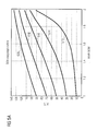
- Fig. 5A shows examples for the mapping f( ) for different values of ⁇ as can be applied in the two-dimensional example shown in Fig. 4 .
- the zoom control factor of d 1, i.e., no zoom is applied, the angles are equal to the original DOA ⁇ .
- ⁇ For increasing zoom control factors, the value of ⁇ is increased, too.
- the function can be derived from geometric considerations or, alternatively, be chosen heuristically.
- remapping of the directions means that each DOA is modified according to the function f().
- the mapping f p (k,n, ⁇ ,d) is performed for every time and frequency bin (k,n).
- the zoom parameter d is depicted as a translational distance d between the original listening position S and the modified listening position S2, as mentioned before, d can also be a factor, e.g. an optical zoom like an 4x or 8x zoom. Especially for the width or filter control, seeing d as a factor, not as a distance, allows for an easy implementation of the acoustical zoom. In other words, the zoom parameter d is in this case a real distance, or at least proportional to a distance.
- embodiments of the invention can also be adapted to support besides the "zoom-in” as described above, e.g. reducing a distance to an object (e.g. to object A in Fig. 4 by moving from position S to position S2), also a "zoom-out", e.g. increasing a distance to an object (e.g. to object A in Fig. 4 by moving from position S2 to position S).
- a zoom-in e.g. reducing a distance to an object (e.g. to object A in Fig. 4 by moving from position S to position S2)
- a "zoom-out" e.g. increasing a distance to an object (e.g. to object A in Fig. 4 by moving from position S2 to position S).
- the inverse considerations apply compared to the zoom-in as described because objects positioned on a side of the listener (e.g. object B with regard to position S2) move to the front of the listener when he moves to position S.
- Fig. 5A shows an exemplarily mapping function (dependent on the zoom factor d) for the direction-of-arrivals for the scenario shown in Fig. 4 .
- Embodiments of the invention can be adapted to use the same mapping function f p for all time and frequency bin values defined by k and n, or, may use different mapping functions for different time values and/or frequency bins.
- the idea behind the filter f d is to change the diffuseness ⁇ such that it lowers the diffuseness for zoomed-in directions ( ⁇ ⁇ l ⁇ l) and increases the diffuseness for out-of-focus directions ( ⁇ >
- certain embodiments of the modification unit 301a are adapted to only use the direction and to assume that all sources, e.g. A and B, defining the direction-of-arrival of the sound have the same distance to the first listening position, e.g. are arranged on a unit radius.
- the mapping function f( ) can be designed such that the maximum angle, to where DOAs are remapped, is limited. For example, a maximum angle of ⁇ 60° is chosen, when the loudspeakers are positioned at ⁇ 60°. This way, the whole sound scene will stay in the front and is only widened, when the zoom is applied.
- the rotational change or difference is derived starting from the first listening orientation respectively first viewing orientation (e.g. direction of the "nose" of the listener respectively viewer) defining a first reference or 0° orientation.
- first viewing orientation e.g. direction of the "nose” of the listener respectively viewer
- reference or 0° orientation changes accordingly. Therefore, embodiments of the present invention change the original angles or directions of arrival of the sound. i.e. the first directional parameter, according to the new reference or 0° orientation such that the second directional parameter represents the same "direction of arrival" in the audio scene, however relative to the new reference orientation or coordinate system. Similar considerations apply to the translation respectively zoom, where the perceived directions-of-arrival change due to the translation or zoom in direction of the first listening orientation (see Fig. 4 ).
- the first directional parameter 114a and the second directional parameter 214a can be two-dimensional or three-dimensional vectors.
- the first directional parameter 114a can be a vector
- the control signal 402 is a rotation control signal defining a rotation angle (e.g. 20° in the aforementioned example) and a rotation direction (to the right in the aforementioned two-dimensional example)
- the diffuseness scaling as, for example, performed by the diffuseness modification unit 301b is described in more detail.
- the diffuseness is scaled with a DOA-dependent window.
- the range of the visual angle covered by the camera image can be taken as a controller for the scaling by which the diffuseness value is increased or decreased.
- zoomed-in-directions or directions-of-interest refer to an angular window of interest, also referred to as central range of angles, that is arranged around the first or original listening direction, e.g. the original 0° reference direction.
- the angular window or central range is determined by the angular values ⁇ defining the border of the angular window.
- the angular window and the width of the angular window can be defined by the negative border angle - ⁇ and the positive border angle ⁇ , wherein the magnitude of the negative border angle may be different to the positive border angle.
- the negative border angle and the positive border angle have the same magnitude (symmetric window or central range of angles centered around the first listening orientation).
- the magnitude of the border angle is also referred to as angular width and the width of the window (from the negative border angle to the positive border angle) is also referred to as total angular width.
- direction-of-arrival parameters, diffuseness parameters, and/or direct or diffuse components can be modified differently depending on whether the original direction-of-arrival parameter is inside the window of interest, e.g. whether the DOA-angle or a magnitude of the DOA-angle relative to the first listening position is smaller than the magnitude of the border angle or angular width ⁇ , or whether the original direction-of-arrival parameter is outside the window of interest, e.g. whether the DOA-angle or a magnitude of the DOA-angle relative to the first listening position is larger than the magnitude of the border angle or angular width ⁇ .
- This is also referred to as direction-dependent and the corresponding filter functions as direction dependent filter functions, wherein the angular width or border angle ⁇ defines the angle at which the corresponding filter changes from increasing the parameter to decreasing the parameter or vice versa.
- the diffuseness modification unit 301b is adapted to modify the diffuseness ⁇ by the function f d (k,n, ⁇ ,d) or f d which is dependent on the time/frequency indices k,n, the original direction-of-arrival ⁇ , and the zoom controller d.
- Fig. 5B shows an embodiment of a filter function f d .
- the filter f d may be implemented as an inversion of the filter function H 1 , which will be explained later, however, adapted to match the diffuseness range, for example the range between [0..1].
- FIG. 5B shows the mapping function or filter f d , wherein the x-axis represents the original or first diffuseness ⁇ , in Fig. 5B also referred to as ⁇ in , with the range from 0 to 1, and the y-axis represents the second or modified diffuseness ⁇ mod also in the range of 0 to 1.
- Reference sign 552 depicts the bypass line.
- Fig. 5B shows some prototype functions of f d , namely 562, 564, 572 and 574 depending on the look width or angular width ⁇ .
- the angular width is smaller for ⁇ 2 than for ⁇ 1 , i.e. ⁇ 2 ⁇ ⁇ 1 .
- ⁇ 2 corresponds to a higher zoom factor d than ⁇ 1 .
- the area below the bypass line 552 defines the modified diffuseness values ⁇ mod in case the original direction-of-arrival ⁇ is within the angular width ⁇ which is reflected by a reduction of the modified diffuseness value ⁇ mod compared to the original diffuseness value ⁇ in or ⁇ after the mapping by the filter f d .
- the area above the bypass line 552 represents the mapping of the original diffuseness ⁇ to the modified diffuseness values ⁇ mod in case the original direction-of-arrival ⁇ is outside the window. In other words, the area above the bypass line 552 shows the increase of the diffuseness after the mapping.
- the angular width ⁇ decreases with an increasing zoom factor d.
- embodiments can be adapted such that the zoom factor d or translation information not only influences the angular width ⁇ of the filter function f d but also the degree or factor the diffuseness is increased in case it is inside the window and the degree or factor the diffuseness ⁇ is decreased in case it is outside the window defined by the angular width ⁇ .
- the zoom factor d or translation information not only influences the angular width ⁇ of the filter function f d but also the degree or factor the diffuseness is increased in case it is inside the window and the degree or factor the diffuseness ⁇ is decreased in case it is outside the window defined by the angular width ⁇ .
- the angular width ⁇ 1 corresponds to a zoom factor d 1
- the angular width ⁇ 2 corresponds to a zoom factor d 2
- d 2 is larger than d 1 and, thus, the angular width ⁇ 2 is smaller than angular width ⁇ 1
- the function f d represented by reference sign 564 and corresponding to the larger zoom factor d 2 maps the original diffuseness values ⁇ in to lower modified diffuseness values ⁇ mod than the filter function f d represented by 562 corresponding to the lower zoom factor d 1 .
- embodiments of the filter function can be adapted to reduce the original diffuseness the more the smaller the angular width ⁇ .
- embodiments of the filter function f d can be adapted to map the original diffuseness ⁇ in to the modified diffuseness ⁇ mod dependent on the zoom factor d and the angular width ⁇ , or the higher the zoom factor d the smaller the angular width ⁇ and/or the higher the increase of the diffuseness for direction-of-arrival ⁇ outside the window.
- the same direction dependent window or filter function f d (k,n, ⁇ ,d) is applied for all zoom factors.
- the use of different direction dependent window or filter functions with smaller angular widths for higher translation or zoom factors matches the audio experience of the user better and provides a more realistic audio perception.
- the application of different mapping values for different zoom factors (higher reduction of the diffuseness with increasing zoom factor for direction-of-arrival value ⁇ inside the window, and increasing or higher diffuseness values for higher zoom factors in case the direction-of-arrival value ⁇ is outside the angular width ⁇ ) even further improve the realistic audio perception.
- the filters for the downmix signal are used to modify the gain of the direct and diffuse part of the output signal.
- the loudspeaker signals are thus modified.
- the sound of the zoomed-in area is amplified, while sound from out-of-interest directions can be attenuated.
- the downmix signal 112 may be a mono or a stereo signal for directional audio coding (DirAC) or spatial audio microphones (SAM), in the following, two different embodiments of the modification are described.
- DIAC directional audio coding
- SAM spatial audio microphones
- a mono downmix modification i.e. an embodiment for a modification of a mono downmix audio signal W 112 is described.
- W k ⁇ n S k ⁇ n + N k ⁇ n
- S(k,n) denotes the direct sound component of the downmix signal
- N(k,n) denotes the diffuse sound components in the original downmix signal
- k denotes the time index or time instant the signal represents and n represents a frequency bin or frequency channel of the signal at the given time instant k .
- H1(k,n, ⁇ ,d) and H2(k,n, ⁇ ,d) represent filters applied to the direct and the diffuse components of the signal model
- ⁇ represents the original direction-of-arrival and d the zoom factor or zoom parameter.
- Both filters are directional dependent weighting functions.
- a cardioid shaped pickup pattern of a microphone can be taken as a design criterion for such weighting functions.
- the filter H 1 (k,n, ⁇ ,d) can be implemented as a raised cosine window such that the direct sound is amplified for directions of the zoomed-in area, whereas the level of sound coming from other directions is attenuated.
- different window shapes can be applied to the direct and the diffuse sound components, respectively.
- the gain filter implemented by the windows may be controlled by the actual translation or zoom control factor d.
- the zoom controls the width of equal gain for the focused directions and the width of gain in general. Examples for different gain windows are given in Fig. 6 .
- Fig. 6 shows different gain windows for the weighting filter H 1 (k,n, ⁇ ,d). Four different gain prototypes are shown:
- the first listening orientation represented by 0° in Fig. 6 , forms the center of different zoom factor dependent direction dependent windows, wherein the predetermined central range or width of the direction dependent windows is the smaller the greater the zoom factor.
- the borders of the central range or window are defined by the angle ⁇ at which the gain is 0 dB.
- Fig. 6 shows symmetric windows with positive and negative borders having the same magnitude.
- Window 616 has a width of 140° for the maximum gain and a predetermined central region with a width of 180° with borders or angular widths +/- ⁇ 3 at +/- 90°, wherein direct components inside or within the predetermined central region are increased and direct components outside of the predetermined central region are reduced (negative gain down to -2.5dB).
- Window 618 has a width of 30° for the maximum gain and a predetermined central region with a width of 60° with borders or angular widths +/- ⁇ 4 at +/- 30°, wherein direct components inside or within the predetermined central region are increased and direct components outside of the predetermined central region are reduced (negative gain down to -6dB).
- the zoom factor d controls the width, i.e. the negative and positive borders and the total width, and the gain of the prototype windows.
- the window can already be designed such that the width and the gain is correctly applied to the original direction-of-arrivals ⁇ .
- the maximal gain should be limited, in order to avoid distortions in the output signals.
- the width of the window, or the exact shape as shown here should be considered as an illustrative example of how the zoom factor controls various aspects of a gain window. Other implementation may be used in different embodiments.
- the filter H 2 (k,n, ⁇ , d ) is used to modify the diffuse part 112a of the downmix signal analogously to the way how the diffuseness measure ⁇ (k,n) has been modified and can be implemented as a subcardioid window as shown in Fig. 7 .
- Fig. 7 shows a subcardioid window 702 which almost keeps the diffuse component unaltered in an area between -30° and +30° of the original direction of arrival ⁇ and attenuate the diffuse component the higher the deviation, i.e. the angle departing from the 0° orientation, of the original direction-of arrival ⁇ .
- the diffuse signal components in the downmix signal remain unaltered. This will result in a more direct sound reproduction in zoom direction.
- the sounds that come from all other directions are rendered more diffuse, as the microphone has been virtually placed farther away.
- those diffuse parts will be attenuated compared to those of the original downmix signal.
- the desired gain filter can also be designed using the previously described raised cosine windows. Note, however, that the scaling will be less pronounced than in case of the direct sound modification.
- the windows can depend on the zoom factor, wherein the slope of the window function 702 is the steeper the higher the zoom factor.
- a stereo downmix modification i.e. a modification of a stereo downmix signal W is described.
- the signal S(k,n) represents direct sound
- N i denotes the diffuse sound for the i -th microphone.
- the direct and diffuse sound components can be determined from the downmix channels based on the diffuseness measure.
- the gain factor c corresponds to a different scaling of the direct sound component in the different stereo channels, which arises from the different directivity pattern associated with the two downmix channels. More details on the relation of the scaling factor and the DOA of direct sound can be found in SAM. Since this scaling depends on the DOA of sound of the observed sound field, its value has to be modified in accordance to the DOA remapping resulting from the modified virtual recording location.
- the computation of the gain filters G ij (k,n, ⁇ ,d) is performed in accordance to the corresponding gain filters H i (k,n, ⁇ ,d) as discussed for the mono downmix case.
- the new stereo scaling factor c mod is determined as a function of the modified DOA such that it corresponds to the new virtual recording location.
- embodiments of the present invention provide an apparatus 300 for converting a first parametric spatial audio signal 112, 114 representing a first listening position or a first listening orientation in a spatial audio scene to a second parametric spatial audio signal 212, 214 representing a second listening position or a second listening orientation, the second listening position or second listening orientation being different to the first listening position or first listening orientation.
- the apparatus comprises a spatial audio signal modification unit 301, 302 adapted to modify the first parametric spurious audio signal 112, 114 dependent on a change of the first listening position or the first listening orientation so as to obtain the second parametric spatial audio signal 212, 214, wherein the second listening position or the second listening orientation corresponds to the first listening position or the first listening orientation changed by the change.
- Embodiments of the apparatus 300 can be adapted to convert only a single side information parameter, for example, the direction-of-arrival 114a or the diffuseness parameter 114b, or only the audio downmix signal 112 or some or all of the aforementioned signals and parameters.
- a single side information parameter for example, the direction-of-arrival 114a or the diffuseness parameter 114b, or only the audio downmix signal 112 or some or all of the aforementioned signals and parameters.
- the analog microphone signals are digitized and processed to provide a downmixed time/frequency representation W(k,n) of the microphone signals, representing, for each time instant or block k , a frequency representation, wherein each frequency bin of the frequency or spectral representation is denoted by the index n .
- the spatial audio analysis unit 100 determines for each time instant k and for each frequency bin n for the corresponding time instant k , one unit vector e DOA (confer equation (4)) providing for each frequency bin n and each time instant k , the directional parameter or information.
- the spatial audio analysis unit 100 determines for each time instant k and each frequency bin n , a diffuseness parameter ⁇ defining a relation between the direct sound or audio components and the diffuse sound or audio components, wherein the diffuse components are, for example, caused by two or more audio sources and/or by reflections of audio signals from the audio sources.
- the DirAC is a very processing efficient and memory efficient coding as it reduces the spatial audio information defining the audio scene, for example, audio sources, reflection, position and orientation of the microphones and respectively the listener (for each time instant k and each frequency bin n ) to one directional information, i.e. a unit vector e DOA (k,n) and one diffuseness value ⁇ (k,n) between 0 and 1, associated to the corresponding one (mono) downmix audio signal W(k,n) or several (e.g. stereo) downmix audio signals W 1 (k,n) and W 2 (k,n).
- a unit vector e DOA (k,n) and one diffuseness value ⁇ (k,n) between 0 and 1 associated to the corresponding one (mono) downmix audio signal W(k,n) or several (e.g. stereo) downmix audio signals W 1 (k,n) and W 2 (k,n).
- Embodiments using the aforementioned directional audio coding are, therefore, adapted to modify, for each instant k and each frequency bin n , the corresponding downmix value W(k,n) to W mod (k,n), the corresponding direction-of-arrival parameter value e (k,n) to e mod (k,n) (in Figs. 1 to 3 represented by ⁇ , respectively ⁇ mod ) and/or diffuseness parameter value ⁇ (k,n) to ⁇ mod (k,n).
- the spatial audio signal modification unit comprises or is formed by, for example, the parameter modification unit 301 and the downmix modification unit 302.
- the parameter modification unit 301 is adapted to process the original parameter 114a to determine the modified directional parameter 214a, to process the diffuseness parameter ⁇ depending on the original directional parameter ⁇ , respectively 114a, to split the downmix signal 112 using equations (2) and (3) using the original diffuseness parameter ⁇ , respectively 114b, and to apply the direction dependent filtering H 1 (k,n, ⁇ ,d) and H 2 (k,n, ⁇ ,d) dependent on the original directional parameter ⁇ , respectively 114a.
- these modifications are performed for each time instant k and each frequency bin n to obtain, for each time instant k and each frequency instant n , the respective modified signals and/or parameters.
- the apparatus 300 is adapted to only modify the first directional parameter 114a of the first parametric spatial audio signal to obtain a second directional parameter 214a of the second parametric spatial audio signal depending on the control signal 402, for example, a rotation control signal or a zoom control signal.
- a corresponding modification or shift of the directional parameter ⁇ (k,n) 114a is sufficient.
- the corresponding diffuseness parameters and downmix signal components can be left un-amended so that the second downmix signal 212 corresponds to the first downmix signal 112 and the second diffuseness parameter 214b corresponds to the first diffuseness parameter 114b.
- a modification of the directional parameter ⁇ (k,n) 114a according to a remapping function as shown in Fig. 5A already improves the sound experience and provides for a better synchronization between the audio signal and, for example, a video signal compared to the unmodified or original parametric spatial audio signal (without modifying the diffuseness parameter or the downmix signal).
- the apparatus 300 is adapted to only apply filter H 1 (k,n, ⁇ ,d). In other words, this embodiment does not perform direction-of-arrival remapping or diffuseness modification.
- This embodiment is adapted to only determine, for example, the direct component 112a from the downmix signal 112 and to apply the filter function H 1 to the direct component to produce a direction dependent weighted version of the direct component.
- Such embodiments may be further adapted to use the direction dependent weighted version of the direct component as modified downmix signal W mod 212, or to also determine the diffuse component 112b from the original downmix signal W 112 and to generate the modified downmix signal W mod 212 by adding, or in general combining, the direction dependent weighted version of the direct component and the original or unaltered diffuse component 112b.
- An improved impression of the acoustic zooming can be achieved, however, the zoom effect is limited because the direction-of-arrival is not modified.
- the filters H 1 (k,n, ⁇ ,d) and H 2 (k,n, ⁇ ,d) are both applied, however, no direction-of-arrival remapping or diffuseness modification is performed.
- the acoustic impression is improved compared to the unamended or original parametric spatial audio signal 112, 114.
- the zooming impression is also better than only applying filter function H 1 (k,n, ⁇ ,d) to the direct component when diffuse sound is present, however, is still limited, because the direction-of-arrival ⁇ is not modified (better than the aforementioned embodiment using only H 1 (k,n, ⁇ ,d),.
- only the filter f d is applied, or in other words, only the diffuseness component ⁇ is modified.
- the zooming effect is improved compared to the original parametric spatial audio signal 112, 114 because the diffuseness of zoomed in areas (areas of interest) are reduced and the diffuseness values of out-of-interest are increased.
- Such embodiments provide a very good zoom impression that is better than only applying the direction-of-arrival remapping.
- Embodiments applying the direction-of-arrival remapping according to function f p in combination with a downmix modification using both filter functions H 1 (k,n, ⁇ ,d) and H 2 (k,n, ⁇ ,d) provide even better zoom impressions than only applying the direction-of-arrival remapping combined with applying the first filter function H 1 alone.
- the apparatus 300 can be adapted to only modify the directional parameter ⁇ (k,n) and the diffuseness parameter ⁇ (k,n), but not to modify the downmix signal W(k,n) 100.
- Preferred embodiments of the apparatus 300 as mentioned above also comprise modifying the downmix signal W(k,n) to even further improve the audio experience with regard to the changed position in the spatial audio scene.
- the parameter modification unit 301 is adapted to shift or modify the first directional parameter by an angle defined by a rotation control signal in a reverse direction to a direction defined by the rotation control signal to obtain the second directional parameter ⁇ mod (k,n) 214a.
- the parameter modification unit 301 is adapted to obtain the second directional parameter 214a using a non-linear mapping function (as, for example, shown in Fig. 5A ) defining the second directional parameter 214a depending on the first directional parameter ⁇ (k,n) and a zoom factor d defined by a zoom control signal 402 or another translational control information defined by the change signal.
- a non-linear mapping function as, for example, shown in Fig. 5A
- a zoom factor d defined by a zoom control signal 402 or another translational control information defined by the change signal.
- the parameter modification unit 301 can be adapted to modify the first diffuseness parameter ⁇ (k,n) 114b of the first parametric spatial audio signal to obtain a second diffuseness parameter ⁇ mod (k,n) 214b depending on the first directional parameter ⁇ (k,n) 114a.
- the parameter modification unit 301, 310b is adapted to obtain the second diffuseness parameter 214b using a direction dependent function adapted to decrease the first diffuseness parameter 114b to obtain the second diffuseness parameter 214b in case the first directional parameter 114a is within a predetermined central range of the second directional parameter with the second or changed listening orientation forming the center of the predetermined two-dimensional or three-dimensional central range and/or to increase the first diffuseness parameter 114b to obtain the second diffuseness parameter in case the first directional parameter 114a is outside of the predetermined central range.
- the first or original listening orientation defines a center, e.g.
- a positive and a negative border of the predetermined central range is defined by a positive and a negative angle ⁇ in a two-dimensional (e.g. horizontal) plane (e.g. +/-30°) independent of whether the second listening orientation is a two-dimensional or a three-dimensional vector, or by a corresponding angle ⁇ (e.g. 30°) defining a right circular cone around the three-dimensional first listening orientation.
- Further embodiments can comprise different predetermined central regions or windows, symmetric and asymmetric, arranged or centered around the first listening orientation or a vector defining the first listening orientation.
- the direction-dependent function f d ( k,n, ⁇ ,d ) depends on the change signal, for example, the zoom control signal, wherein the predetermined central range, respectively the values ⁇ defining the negative and positive border (or in general the border) of the central range is the smaller the greater the translational change or the higher the zoom factor defined by the zoom control signal is.
- the spatial audio signal modification unit comprises a downmix modification unit 302 adapted to modify the first downmix audio signal W(k,n) of the first parametric spatial audio signal to obtain a second downmix signal W mod (k,n) of the second parametric spatial audio signal depending on the first directional parameter ⁇ (k,n) and the first diffuseness parameter ⁇ (k,n) .
- Embodiments of the downmix modification unit 302 can be adapted to split the first downmix audio signal W into a direct component S(k,n) 112a and a diffuse component N(k,n) 112b dependent on the first diffuseness parameter ⁇ (k,n) , for example, based on equations (2) and (3).
- the downmix modification unit 302 is adapted to apply a first direction dependent function H 1 (k,n, ⁇ ,d) to obtain a direction dependent weighted version of the direct component and/or to apply a second direction dependent function H 2 (k,n, ⁇ ,d) to the diffuse component to obtain a direction-dependent weighted version of the diffuse component.
- the downmix modification unit 302 can be adapted to produce the direction dependent weighted version of the direct component 112a by applying a further direction dependent function H 1 (k,n, ⁇ ,d) to the direct component, the further direction dependent function being adapted to increase the direct component 112a in case the first directional parameter 114a is within the further predetermined central range of the first directional parameters and/or to decrease the direct component 112a in case the first directional parameter 114a is outside of the further predetermined range of the second directional parameters.
- H 1 k,n, ⁇ ,d
- the downmix modification unit can be adapted to produce the direction dependent weighted version of the diffusecomponent 112b by applying a direction dependent function H 2 (k,n, ⁇ ,d) to the diffuse component 112b, the direction dependent function being adapted to decrease the diffuse component in case the first directional parameter 114a is within a predetermined central range of the first directional parameters and/or to increase the diffuseness component 112b in case the first directional parameter 114a is outside of the predetermined range of the second directional parameters.
- the downmix modification unit 302 is adapted to obtain the second downmix signal 212 based on a combination, e.g. a sum, of a direction dependent weighted version of the direct component 112a and a direction dependent weighted version of the diffuse component 112b.
- a combination e.g. a sum
- further embodiments may apply other algorithms than summing the two components to obtain the modified downmix signal 212.
- embodiments of the downmix modification unit 302 can be adapted to split up the downmix signal W into a diffuse part or component 112b and a non-diffuse or direct part or component 112a by two multiplicators, namely ( ⁇ ) 1/2 and (1 - ⁇ ) 1/2 and to filter the non-diffuse part 112a by filter function H 1 and to filter the diffuse part 112b by filter function H 2 .
- the filter function H 1 or H 1 (k,n, ⁇ ,d) can be dependent on the time/frequency indices k, n, the original direction-of-arrival ⁇ and the zoom parameter d.
- the filter function H 1 may be additionally dependent on the diffuseness ⁇ .
- the filter function H 2 or H 2 (k,n, ⁇ ,d) can be dependent on the time/frequency indices k, n, the original direction-of-arrival ⁇ , and the zoom parameter d.
- the filter function H 2 may be additionally dependent on the diffuseness ⁇ .
- the filter function H 2 can be implemented as a subcardioid window as shown in Fig. 7 , or as a simple attenuation factor, independent of the direction-of-arrival ⁇ .
- the zoom parameter d can be used to control the filters H 1 , H 2 and the modifiers or functions f d and f p (see Fig. 3A ).
- the zoom parameter d can also control the look width or angular width ⁇ (also referred to as border angle ⁇ ) of the applied windows or central regions.
- the width ⁇ is defined, e.g. as the angle at which the filter function has 0 dB (see e.g. the 0 dB line in Fig. 6 ).
- the angular width ⁇ and/or the gain can be controlled by the zoom parameter d.
- An example of different values for ⁇ and different maximum gains and minimum gains is given in Fig. 6 .
- FIG. 4 where ⁇ corresponds to the original directional parameter ⁇ and ⁇ corresponds to the modified directional parameter ⁇ mod (for zoom-in), the higher zoom factor d, the more object B moves from a central or frontal position to a side position, or even (in case of even higher zoom factors d than shown in Fig. 4 ) to a position in the back of the virtually modified position.
- the zoom factor d the more the magnitude of an initially small angle representing a position in a frontal area of the listener increases, wherein higher angles represent positions in a side area of the listener.
- This modification of the directional parameter is taken into account by applying a function as shown in Fig. 5A .
- the direction dependent windows or functions for the other parameters and for the direct and diffuse components can also be designed to take into account the modification of the original directional parameter or angle, by reducing the angular width ⁇ with increasing zoom d, for example in a non-linear manner corresponding to the direction-of-arrival or directional parameter mapping as shown in Fig. 5A .
- these direction dependent windows or functions can be adapted such that the original directional parameter can be directly used (e.g. without prior modification by function f p ), or alternatively, first the directional parameter mapping f p is performed and afterwards the direction dependent weighting f d , H 1 and/or H 2 based on the modified directional parameter is performed in a similar manner.
- directional dependent functions f d , H 1 and H 2 referring directly to ⁇ , representing the original directional parameter (for zoom-in), or directional dependent functions f d , H 1 and H 2 referring to ⁇ representing the modified directional parameter.
- Embodiments using the modified directional parameter can employ, similar to the embodiments using the original directional parameter, different windows with different angular widths and/or different gains for different zoom factors, or, the same windows with the same angular width (because the directional parameter has already been mapped to reflect the different zoom factors) and the same gain, or windows with the same angular widths but different gains, wherein a higher zoom factor results in a higher gain (analog to the windows in Fig. 6 ).
- Fig. 3B shows a further embodiment of the apparatus.
- the spatial audio signal modification unit in Fig. 3B comprises or is formed by, for example, the parameter modification unit 301 and the downmix modification unit 302.
- the parameter modification unit 301 is adapted to first process the original parameter 114a to determine the modified directional parameter 214a, to then process the diffuseness parameter ⁇ depending on the modified directional parameter ⁇ mod , respectively 214a, to split the downmix signal 112 using equations (2) and (3) and the original diffuseness parameter ⁇ , respectively 114b as described based on Fig. 3A , and to apply the direction dependent filtering H 1 and H 2 dependent on the modified directional parameter ⁇ mod , respectively 214a.
- these modifications are performed for each time instant k and each frequency bin n to obtain, for each time instant k and each frequency instant n, the respective modified signals and/or parameters.
- the parameter modification unit 301 is adapted to process the original parameter 114a to determine the modified directional parameter 214a, to process the diffuseness parameter ⁇ depending on the original directional parameter ⁇ or 114a, to determine the modified diffuseness parameter ⁇ mod or 214b, to split the downmix signal 112 using equations (2) and (3) and the original diffuseness parameter ⁇ or 114b as described based on Fig. 3A , and to apply the direction dependent filtering H 1 and H 2 dependent on the modified directional parameter ⁇ mod , or 214a.
- the apparatus 300 is adapted to only modify the first directional parameter 114a of the first parametric spatial audio signal to obtain a second directional parameter 214a of the second parametric spatial audio signal depending on the control signal 402, for example, a rotation control signal or a zoom control signal.
- a corresponding modification or shift of the directional parameter ⁇ (k,n) 114a is sufficient.
- the corresponding diffuseness parameters and downmix signal components can be left un-amended so that the second downmix signal 212 corresponds to the first downmix signal 112 and the second diffuseness parameter 214b corresponds to the first diffuseness parameter 114b.
- a modification of the directional parameter ⁇ (k,n) 114a according to a remapping function as shown in Fig. 5A already improves the sound experience and provides for a better synchronization between the audio signal and, for example, a video signal compared to the unmodified or original parametric spatial audio signal (without modifying the diffuseness parameter or the downmix signal).
- Modifying the diffuseness parameter 114b further improves the audio experience or, in other words, improves the adaptation of the sound experience with regard to the changed position within the spatial audio scene. Therefore, in further embodiments, the apparatus 300 can be adapted to only modify the directional parameter ⁇ (k,n) and the diffuseness parameter ⁇ (k,n), the latter dependent on the modified directional parameter ⁇ mod (k,n), but not to modify the downmix signal W(k,n) 100.
- Preferred embodiments of the apparatus 300 according to Fig. 3B also comprise modifying the downmix signal W(k,n) dependent on the original diffuseness ⁇ (k,n) and the modified directional parameter ⁇ mod (k,n) to even further improve the audio experience with regard to the changed position in the spatial audio scene.
- the parameter modification unit 301 is adapted to shift or modify the first directional parameter by an angle defined by a rotation control signal in a reverse direction to a direction defined by the rotation control signal to obtain the second directional parameter ⁇ mod (k,n) 214a.
- the parameter modification unit 301 is adapted to obtain the second directional parameter 214a using a non-linear mapping function (as, for example, shown in Fig. 5A ) defining the second directional parameter 214a depending on the first directional parameter ⁇ (k,n) and a zoom factor d defined by a zoom control signal 402 or another translational control information defined by the change signal.
- a non-linear mapping function as, for example, shown in Fig. 5A
- a zoom factor d defined by a zoom control signal 402 or another translational control information defined by the change signal.
- the parameter modification unit 301 can be adapted to modify the first diffuseness parameter ⁇ (k,n) 114b of the first parametric spatial audio signal to obtain a second diffuseness parameter ⁇ mod (k,n) 214b depending on the second directional parameter ⁇ mod (k,n) 214a.
- the parameter modification unit can be further adapted to obtain the second diffuseness parameter ⁇ mod (k,n) using a direction dependent function adapted to decrease the first diffuseness parameter ⁇ (k,n) to obtain the second diffuseness parameter ⁇ mod (k,n) in case the second directional parameter ⁇ mod (k,n) is within a predetermined central range, for example +/- 30° of the original reference orientation referred to as original 0° orientation, and/or to increase the first diffuseness parameter ⁇ (k,n) to obtain the second diffuseness parameter ⁇ mod (k,n) in case the second directional parameter ⁇ mod (k,n) is outside of the predetermined central range, for example, in a two-dimensional case outside the central range defined by +30° and -30° from the 0° original reference orientation.
- the parameter modification unit 301, 310b is adapted to obtain the second diffuseness parameter 214b using a direction dependent function adapted to decrease the first diffuseness parameter 114b to obtain the second diffuseness parameter 214b in case the second directional parameter 214a is within a predetermined central range of the second directional parameter with the first or original listening orientation forming the center of the predetermined two-dimensional or three-dimensional central range and/or to increase the first diffuseness parameter 114b to obtain the second diffuseness parameter in case the second directional parameter 214a is outside of the predetermined central range.
- the first listening orientation defines a center, e.g.
- a positive and a negative border of the predetermined central range is defined by a positive and a negative angle in a two-dimensional (e.g. horizontal) plane (e.g. +/-30°) independent of whether the first listening orientation is a two-dimensional or a three-dimensional vector, or by a corresponding angle (e.g. 30°) defining a right circular cone around the three-dimensional second listening orientation.
- Further embodiments can comprise different predetermined central regions, symmetric and asymmetric, arranged around the first listening orientation or vector defining the first listening orientation.
- the direction-dependent function f d ( ⁇ ) depends on the change signal, for example, the zoom control signal, wherein the predetermined central range, respectively the values defining the negative and positive border (or in general the border) of the central range is the smaller the greater the translational change or the higher the zoom factor defined by the zoom control signal is.
- the spatial audio signal modification unit comprises a downmix modification unit 302 adapted to modify the first downmix audio signal W(k,n) of the first parametric spatial audio signal to obtain a second downmix signal W mod (k,n) of the second parametric spatial audio signal depending on the second directional parameter ⁇ mod (k,n) and the first diffuseness parameter ⁇ (k,n).
- Embodiments of the downmix modification unit 302 can be adapted to split the first downmix audio signal W into a direct component S(k,n) 112a and a diffuse component N(k,n) 112b dependent on the first diffuseness parameter ⁇ (k,n), for example, based on equations (2) and (3).
- the downmix modification unit 302 is adapted to apply a first direction dependent function H 1 to obtain a direction dependent weighted version of the direct component and/or to apply a second direction dependent function H 2 to the diffuse component to obtain a direction-dependent weighted version of the diffuse component.
- the downmix modification unit 302 can be adapted to produce the direction dependent weighted version of the direct component 112a by applying a further direction dependent function H 1 to the direct component, the further direction dependent function being adapted to increase the direct component 112a in case the second directional parameter 214a is within the further predetermined central range of the second directional parameters and/or to decrease the direct component 112a in case the second directional parameter 214a is outside of the further predetermined range of the second directional parameters.
- the downmix modification unit can be adapted to produce the direction dependent weighted version of the diffuse component 112b by applying a direction dependent function H 2 to the diffuse component 112b, the direction dependent function being adapted to decrease the diffuse component in case the second directional parameter 214a is within a predetermined central range of the second directional parameters and/or to increase the diffuse component 112b in case the second directional parameter 214a is outside of the predetermined range of the second directional parameters.
- the downmix modification unit 302 is adapted to obtain the second downmix signal 212 based on a combination, e.g. a sum, of a direction dependent weighted version of the direct component 112a and a direction dependent weighted version of the diffuse component 112b.
- a combination e.g. a sum
- further embodiments may apply other algorithms than summing the two components to obtain the modified downmix signal 212.
- embodiments of the downmix modification unit 302 according to Fig. 3B can be adapted to split up the downmix signal W into a diffuse part or component 112b and a non-diffuse or direct part or component 112a by two multiplicators, namely ( ⁇ ) 1/2 and (1 - ⁇ ) 1/2 and to filter the non-diffuse part 112a by filter function H 1 and to filter the diffuse part 112b by filter function H 2 .
- the filter function H 1 or H 1 ( ⁇ , ⁇ ) can be dependent on the time/frequency indices k, n, the modified direction-of-arrival and the zoom parameter d.
- the filter function H 1 may be additionally dependent on the diffuseness ⁇ .
- the filter function H 2 or H 2 ( ⁇ , ⁇ ) can be dependent on the time/frequency indices k, n, the original direction-of-arrival ⁇ , and the zoom parameter d.
- the filter function H 2 or H 2 ( ⁇ , ⁇ ) may be additionally dependent on the diffuseness ⁇ .
- the filter function H 2 can be implemented as a subcardioid window as shown in Fig. 7 , or as a simple attenuation factor, independent of the modified direction-of-arrival ⁇ mod .
- the zoom parameters d can be used to control the filters H 1 , H 2 and the modifiers or functions f d and f p .
- the zoom parameter d can also control the angular width ⁇ (also referred to as border angle ⁇ ) of the applied windows or central regions.
- the width ⁇ is defined, e.g. as the angle at which the filter function has 0 dB (analog to the 0 dB line in Fig. 6 ).
- the angular width ⁇ and/or the gain can be controlled by the zoom parameter d.
- inventive embodiments lead to an improved experience of a joint video/audio playback by adjusting the perceived audio image to the zoom control of a video camera.
- Modem camcorders for example, for home entertainment, are capable of recording surround sound and have a powerful optical zoom. There is, however, no perceptual equivalent interaction between the optical zoom and the recorded sound, as the recorded spatial sound only depends on the actual position of the camera and, thus, the position of the microphones mounted on the camera itself. In case of a scene filmed in a close-up mode, the invention allows to adjust the audio image accordingly. This leads to a more natural and consistent consumer experience as the sound is zoomed together with the picture.
- the invention may also be applied in a post-processing phase if the original microphone signals are recorded unaltered with the video and no further processing has been done.
- the original zoom length may not be known, the invention can be used in creative audio-visual post-processing toolboxes. An arbitrary zoom-length can be selected and the acoustical zoom can be steered by the user to match the picture. Alternatively, the user can create his own preferred spatial effects. In either case, the original microphone recording position will be altered to a user defined virtual recording position.
- the inventive methods can be implemented in hardware or in software.
- the implementation can be performed using a digital storage medium, in particular, a disc, a CD, a DVD or a Blu-Ray disc having an electronically-readable control signal stored thereon, which cooperates with a programmable computer system such that an embodiment of the inventive method is performed.
- an embodiment of the present invention is, therefore, a computer program produced with a program code stored on a machine-readable carrier, the program code being operative for performing the inventive method when the computer program product runs on a computer.
- embodiments of the inventive method are, therefore, a computer program having a program code for performing at least one of the inventive methods when the computer program runs on a computer.
Priority Applications (15)
| Application Number | Priority Date | Filing Date | Title |
|---|---|---|---|
| CA2784862A CA2784862C (en) | 2009-12-17 | 2010-12-14 | An apparatus and a method for converting a first parametric spatial audio signal into a second parametric spatial audio signal |
| PCT/EP2010/069669 WO2011073210A1 (en) | 2009-12-17 | 2010-12-14 | An apparatus and a method for converting a first parametric spatial audio signal into a second parametric spatial audio signal |
| CN201080063799.9A CN102859584B (zh) | 2009-12-17 | 2010-12-14 | 用以将第一参数式空间音频信号转换成第二参数式空间音频信号的装置与方法 |
| MX2012006979A MX2012006979A (es) | 2009-12-17 | 2010-12-14 | Un aparato y metodo para convertir una primera señal de audio parametrico espacial en una segunda señal de audio parametrico espacial. |
| RU2012132354/08A RU2586842C2 (ru) | 2009-12-17 | 2010-12-14 | Устройство и способ преобразования первого параметрического пространственного аудиосигнала во второй параметрический пространственный аудиосигнал |
| JP2012543696A JP5426035B2 (ja) | 2009-12-17 | 2010-12-14 | 第1のパラメトリック空間オーディオ信号を第2のパラメトリック空間オーディオ信号に変換する装置および方法 |
| ES10796353.0T ES2592217T3 (es) | 2009-12-17 | 2010-12-14 | Un aparato y método para convertir una primera señal de audio paramétrico espacial en una segunda señal de audio paramétrico espacial |
| BR112012015018-9A BR112012015018B1 (pt) | 2009-12-17 | 2010-12-14 | Um aparelho e um método para converter um primeiro sinal de áudio espacial paramétrico em um segundo sinal de áudio espacial paramétrico |
| EP10796353.0A EP2502228B1 (de) | 2009-12-17 | 2010-12-14 | Vorrichtung und Verfahren zur Umwandlung eines ersten parametrisch räumlichen Audiosignals in ein zweites parametrisch räumliches Audiosignal |
| AU2010332934A AU2010332934B2 (en) | 2009-12-17 | 2010-12-14 | An apparatus and a method for converting a first parametric spatial audio signal into a second parametric spatial audio signal |
| KR1020127017311A KR101431934B1 (ko) | 2009-12-17 | 2010-12-14 | 제 1 파라메트릭 공간 오디오 신호를 제 2 파라메트릭 공간 오디오 신호로 변환하기 위한 장치 및 방법 |
| TW099143975A TWI523545B (zh) | 2009-12-17 | 2010-12-15 | 用以將第一參數式空間音訊信號轉換成第二參數式空間音訊信號的裝置與方法 |
| ARP100104731A AR079517A1 (es) | 2009-12-17 | 2010-12-17 | Un aparato y metodo para convertir una primera senal de audio parametrico espacial en una segunda senal de audio para metrico espacial |
| US13/523,085 US9196257B2 (en) | 2009-12-17 | 2012-06-14 | Apparatus and a method for converting a first parametric spatial audio signal into a second parametric spatial audio signal |
| HK13103678.8A HK1176733A1 (zh) | 2009-12-17 | 2013-03-25 | 將第參數空間音頻信號轉換成第二參數空間音頻信號的設備和方法 |
Applications Claiming Priority (1)
| Application Number | Priority Date | Filing Date | Title |
|---|---|---|---|
| US28759609P | 2009-12-17 | 2009-12-17 |
Publications (1)
| Publication Number | Publication Date |
|---|---|
| EP2346028A1 true EP2346028A1 (de) | 2011-07-20 |
Family
ID=43748019
Family Applications (2)
| Application Number | Title | Priority Date | Filing Date |
|---|---|---|---|
| EP10156263A Withdrawn EP2346028A1 (de) | 2009-12-17 | 2010-03-11 | Vorrichtung und Verfahren zur Umwandlung eines ersten parametrisch beabstandeten Audiosignals in ein zweites parametrisch beabstandetes Audiosignal |
| EP10796353.0A Active EP2502228B1 (de) | 2009-12-17 | 2010-12-14 | Vorrichtung und Verfahren zur Umwandlung eines ersten parametrisch räumlichen Audiosignals in ein zweites parametrisch räumliches Audiosignal |
Family Applications After (1)
| Application Number | Title | Priority Date | Filing Date |
|---|---|---|---|
| EP10796353.0A Active EP2502228B1 (de) | 2009-12-17 | 2010-12-14 | Vorrichtung und Verfahren zur Umwandlung eines ersten parametrisch räumlichen Audiosignals in ein zweites parametrisch räumliches Audiosignal |
Country Status (15)
| Country | Link |
|---|---|
| US (1) | US9196257B2 (de) |
| EP (2) | EP2346028A1 (de) |
| JP (1) | JP5426035B2 (de) |
| KR (1) | KR101431934B1 (de) |
| CN (1) | CN102859584B (de) |
| AR (1) | AR079517A1 (de) |
| AU (1) | AU2010332934B2 (de) |
| BR (1) | BR112012015018B1 (de) |
| CA (1) | CA2784862C (de) |
| ES (1) | ES2592217T3 (de) |
| HK (1) | HK1176733A1 (de) |
| MX (1) | MX2012006979A (de) |
| RU (1) | RU2586842C2 (de) |
| TW (1) | TWI523545B (de) |
| WO (1) | WO2011073210A1 (de) |
Cited By (30)
| Publication number | Priority date | Publication date | Assignee | Title |
|---|---|---|---|---|
| EP2600343A1 (de) * | 2011-12-02 | 2013-06-05 | Fraunhofer-Gesellschaft zur Förderung der angewandten Forschung e.V. | Vorrichtung und Verfahren zum Mischen von Raumtoncodierungsstreams auf Geometriebasis |
| EP2733965A1 (de) * | 2012-11-15 | 2014-05-21 | Fraunhofer-Gesellschaft zur Förderung der angewandten Forschung e.V. | Vorrichtung und Verfahren zur Erzeugung mehrerer parametrischer Audioströme und Vorrichtung und Verfahren zur Erzeugung mehrere Lautsprechersignale |
| EP2942982A1 (de) * | 2014-05-05 | 2015-11-11 | Fraunhofer-Gesellschaft zur Förderung der angewandten Forschung e.V. | System, Vorrichtung und Verfahren zur konsistenten Wiedergabe einer akustischen Szene auf Basis von informierter räumlicher Filterung |
| EP3209029A1 (de) * | 2016-02-16 | 2017-08-23 | Sony Corporation | System mit verteilten drahtlosen lautsprechern |
| US9794724B1 (en) | 2016-07-20 | 2017-10-17 | Sony Corporation | Ultrasonic speaker assembly using variable carrier frequency to establish third dimension sound locating |
| US9826330B2 (en) | 2016-03-14 | 2017-11-21 | Sony Corporation | Gimbal-mounted linear ultrasonic speaker assembly |
| US9838821B2 (en) | 2013-12-27 | 2017-12-05 | Nokia Technologies Oy | Method, apparatus, computer program code and storage medium for processing audio signals |
| US9866986B2 (en) | 2014-01-24 | 2018-01-09 | Sony Corporation | Audio speaker system with virtual music performance |
| WO2018050292A1 (fr) * | 2016-09-16 | 2018-03-22 | Benjamin Bernard | Dispositif et procede de captation et traitement d'un champ acoustique tridimensionnel |
| EP3340648A1 (de) * | 2016-12-23 | 2018-06-27 | Nxp B.V. | Verarbeitung von audiosignalen |
| US10021499B2 (en) | 2014-05-13 | 2018-07-10 | Fraunhofer-Gesellschaft Zur Foerderung Der Angewandten Forschung E.V. | Apparatus and method for edge fading amplitude panning |
| WO2018132385A1 (en) * | 2017-01-12 | 2018-07-19 | Pcms Holdings, Inc. | Audio zooming in natural audio video content service |
| WO2018193160A1 (en) * | 2017-04-20 | 2018-10-25 | Nokia Technologies Oy | Ambience generation for spatial audio mixing featuring use of original and extended signal |
| GB2563635A (en) * | 2017-06-21 | 2018-12-26 | Nokia Technologies Oy | Recording and rendering audio signals |
| WO2019097018A1 (en) * | 2017-11-17 | 2019-05-23 | Fraunhofer-Gesellschaft zur Förderung der angewandten Forschung e.V. | Apparatus and method for encoding or decoding directional audio coding parameters using quantization and entropy coding |
| WO2019121864A1 (en) * | 2017-12-19 | 2019-06-27 | Koninklijke Kpn N.V. | Enhanced audiovisual multiuser communication |
| WO2019121773A1 (en) * | 2017-12-18 | 2019-06-27 | Dolby International Ab | Method and system for handling local transitions between listening positions in a virtual reality environment |
| EP3605531A4 (de) * | 2017-03-28 | 2020-04-15 | Sony Corporation | Informationsverarbeitungsvorrichtung, informationsverarbeitungsverfahren und programm |
| US10635383B2 (en) | 2013-04-04 | 2020-04-28 | Nokia Technologies Oy | Visual audio processing apparatus |
| CN111183479A (zh) * | 2017-07-14 | 2020-05-19 | 弗劳恩霍夫应用研究促进协会 | 使用多层描述生成经增强的声场描述或经修改的声场描述的概念 |
| WO2020104726A1 (en) * | 2018-11-21 | 2020-05-28 | Nokia Technologies Oy | Ambience audio representation and associated rendering |
| WO2021032908A1 (en) | 2019-08-16 | 2021-02-25 | Nokia Technologies Oy | Quantization of spatial audio direction parameters |
| WO2021032909A1 (en) * | 2019-08-16 | 2021-02-25 | Nokia Technologies Oy | Quantization of spatial audio direction parameters |
| EP3849202A1 (de) * | 2020-01-10 | 2021-07-14 | Nokia Technologies Oy | Audio- und videoverarbeitung |
| US11232802B2 (en) | 2016-09-30 | 2022-01-25 | Coronal Encoding S.A.S. | Method for conversion, stereophonic encoding, decoding and transcoding of a three-dimensional audio signal |
| WO2022020365A1 (en) * | 2020-07-20 | 2022-01-27 | Orbital Audio Laboratories, Inc. | Multi-stage processing of audio signals to facilitate rendering of 3d audio via a plurality of playback devices |
| RU2777921C2 (ru) * | 2017-12-18 | 2022-08-11 | Долби Интернешнл Аб | Способ и система для обработки локальных переходов между положениями прослушивания в среде виртуальной реальности |
| US11443737B2 (en) | 2020-01-14 | 2022-09-13 | Sony Corporation | Audio video translation into multiple languages for respective listeners |
| WO2023118643A1 (en) * | 2021-12-22 | 2023-06-29 | Nokia Technologies Oy | Apparatus, methods and computer programs for generating spatial audio output |
| US11950085B2 (en) | 2017-07-14 | 2024-04-02 | Fraunhofer-Gesellschaft Zur Foerderung Der Angewandten Forschung E.V. | Concept for generating an enhanced sound field description or a modified sound field description using a multi-point sound field description |
Families Citing this family (48)
| Publication number | Priority date | Publication date | Assignee | Title |
|---|---|---|---|---|
| PL2647222T3 (pl) | 2010-12-03 | 2015-04-30 | Fraunhofer Ges Forschung | Pozyskiwanie dźwięku za pomocą ekstrakcji informacji geometrycznej z estymacji kierunku nadejścia sygnału |
| EP2541547A1 (de) * | 2011-06-30 | 2013-01-02 | Thomson Licensing | Verfahren und Vorrichtung zum Ändern der relativen Standorte von Schallobjekten innerhalb einer Higher-Order-Ambisonics-Wiedergabe |
| EP2727380B1 (de) | 2011-07-01 | 2020-03-11 | Dolby Laboratories Licensing Corporation | Hochmischen von objektbasierten Audiodaten |
| US9047863B2 (en) | 2012-01-12 | 2015-06-02 | Qualcomm Incorporated | Systems, methods, apparatus, and computer-readable media for criticality threshold control |
| CN104054126B (zh) * | 2012-01-19 | 2017-03-29 | 皇家飞利浦有限公司 | 空间音频渲染和编码 |
| WO2013186593A1 (en) * | 2012-06-14 | 2013-12-19 | Nokia Corporation | Audio capture apparatus |
| CN104471641B (zh) | 2012-07-19 | 2017-09-12 | 杜比国际公司 | 用于改善对多声道音频信号的呈现的方法和设备 |
| US9565314B2 (en) | 2012-09-27 | 2017-02-07 | Dolby Laboratories Licensing Corporation | Spatial multiplexing in a soundfield teleconferencing system |
| JP6031930B2 (ja) * | 2012-10-02 | 2016-11-24 | ソニー株式会社 | 音声処理装置および方法、プログラム並びに記録媒体 |
| CN103021414B (zh) * | 2012-12-04 | 2014-12-17 | 武汉大学 | 一种三维音频系统距离调制方法 |
| EP2757559A1 (de) * | 2013-01-22 | 2014-07-23 | Fraunhofer-Gesellschaft zur Förderung der angewandten Forschung e.V. | Vorrichtung und Verfahren zur Codierung räumlicher Audioobjekte mittels versteckter Objekte zur Signalmixmanipulierung |
| US9854377B2 (en) * | 2013-05-29 | 2017-12-26 | Qualcomm Incorporated | Interpolation for decomposed representations of a sound field |
| CN104244164A (zh) * | 2013-06-18 | 2014-12-24 | 杜比实验室特许公司 | 生成环绕立体声声场 |
| EP3933834A1 (de) | 2013-07-05 | 2022-01-05 | Dolby International AB | Verbesserte klangfeldcodierung mittels erzeugung parametrischer komponenten |
| US9883140B2 (en) * | 2014-05-19 | 2018-01-30 | Apple Inc. | Using the location of a near-end user in a video stream to adjust audio settings of a far-end system |
| KR102605480B1 (ko) * | 2014-11-28 | 2023-11-24 | 소니그룹주식회사 | 송신 장치, 송신 방법, 수신 장치 및 수신 방법 |
| US9602946B2 (en) | 2014-12-19 | 2017-03-21 | Nokia Technologies Oy | Method and apparatus for providing virtual audio reproduction |
| CN107533843B (zh) * | 2015-01-30 | 2021-06-11 | Dts公司 | 用于捕获、编码、分布和解码沉浸式音频的系统和方法 |
| KR102617476B1 (ko) * | 2016-02-29 | 2023-12-26 | 한국전자통신연구원 | 분리 음원을 합성하는 장치 및 방법 |
| KR102561371B1 (ko) | 2016-07-11 | 2023-08-01 | 삼성전자주식회사 | 디스플레이장치와, 기록매체 |
| US10187740B2 (en) * | 2016-09-23 | 2019-01-22 | Apple Inc. | Producing headphone driver signals in a digital audio signal processing binaural rendering environment |
| KR20180090022A (ko) * | 2017-02-02 | 2018-08-10 | 한국전자통신연구원 | 다중 전방향 카메라 및 마이크 기반 가상현실 제공 방법 및 가상 현실 제공 방법을 수행하는 음향 신호 처리 장치 및 영상 신호 처리 장치 |
| CN110463226B (zh) * | 2017-03-14 | 2022-02-18 | 株式会社理光 | 声音记录设备,声音系统,声音记录方法和载体装置 |
| BR112019021897A2 (pt) * | 2017-04-25 | 2020-05-26 | Sony Corporation | Dispositivo e método de processamento de sinal, e, programa |
| GB2562518A (en) * | 2017-05-18 | 2018-11-21 | Nokia Technologies Oy | Spatial audio processing |
| US10299039B2 (en) | 2017-06-02 | 2019-05-21 | Apple Inc. | Audio adaptation to room |
| CN111108555B (zh) * | 2017-07-14 | 2023-12-15 | 弗劳恩霍夫应用研究促进协会 | 使用深度扩展DirAC技术或其他技术生成经增强的声场描述或经修改的声场描述的装置和方法 |
| US11004567B2 (en) | 2017-08-15 | 2021-05-11 | Koko Home, Inc. | System and method for processing wireless backscattered signal using artificial intelligence processing for activities of daily life |
| US10412482B2 (en) | 2017-11-08 | 2019-09-10 | Merry Electronics (Shenzhen) Co., Ltd. | Loudspeaker apparatus |
| RU2707149C2 (ru) * | 2017-12-27 | 2019-11-22 | Общество С Ограниченной Ответственностью "Яндекс" | Устройство и способ модифицирования вывода аудиосигнала устройства |
| USD882547S1 (en) | 2017-12-27 | 2020-04-28 | Yandex Europe Ag | Speaker device |
| GB201800918D0 (en) * | 2018-01-19 | 2018-03-07 | Nokia Technologies Oy | Associated spatial audio playback |
| CN109492126B (zh) * | 2018-11-02 | 2022-03-01 | 廊坊市森淼春食用菌有限公司 | 一种智能交互方法及装置 |
| US10810850B2 (en) | 2019-02-19 | 2020-10-20 | Koko Home, Inc. | System and method for state identity of a user and initiating feedback using multiple sources |
| GB2584838A (en) * | 2019-06-11 | 2020-12-23 | Nokia Technologies Oy | Sound field related rendering |
| GB2584837A (en) * | 2019-06-11 | 2020-12-23 | Nokia Technologies Oy | Sound field related rendering |
| WO2021006871A1 (en) | 2019-07-08 | 2021-01-14 | Dts, Inc. | Non-coincident audio-visual capture system |
| USD947152S1 (en) | 2019-09-10 | 2022-03-29 | Yandex Europe Ag | Speaker device |
| GB2587335A (en) | 2019-09-17 | 2021-03-31 | Nokia Technologies Oy | Direction estimation enhancement for parametric spatial audio capture using broadband estimates |
| US11719804B2 (en) | 2019-09-30 | 2023-08-08 | Koko Home, Inc. | System and method for determining user activities using artificial intelligence processing |
| US11240635B1 (en) * | 2020-04-03 | 2022-02-01 | Koko Home, Inc. | System and method for processing using multi-core processors, signals, and AI processors from multiple sources to create a spatial map of selected region |
| US11184738B1 (en) | 2020-04-10 | 2021-11-23 | Koko Home, Inc. | System and method for processing using multi core processors, signals, and AI processors from multiple sources to create a spatial heat map of selected region |
| EP4226366A2 (de) * | 2020-10-09 | 2023-08-16 | Fraunhofer-Gesellschaft zur Förderung der angewandten Forschung e.V. | Vorrichtung, verfahren oder computerprogramm zur verarbeitung einer codierten audioszene mit einer bandbreitenerweiterung |
| MX2023003962A (es) * | 2020-10-09 | 2023-05-25 | Fraunhofer Ges Forschung | Aparato, metodo, o programa de computadora para procesar una escena de audio codificada utilizando una conversion de parametros. |
| TWI805019B (zh) * | 2020-10-09 | 2023-06-11 | 弗勞恩霍夫爾協會 | 使用參數平滑處理編碼音頻場景的裝置、方法或電腦程式 |
| WO2022115803A1 (en) * | 2020-11-30 | 2022-06-02 | The Regents Of The University Of California | Systems and methods for sound-enhanced meeting platforms |
| CN115472170A (zh) * | 2021-06-11 | 2022-12-13 | 华为技术有限公司 | 一种三维音频信号的处理方法和装置 |
| CN115086861B (zh) * | 2022-07-20 | 2023-07-28 | 歌尔股份有限公司 | 音频处理方法、装置、设备及计算机可读存储介质 |
Citations (3)
| Publication number | Priority date | Publication date | Assignee | Title |
|---|---|---|---|---|
| EP1473971A2 (de) * | 2003-04-07 | 2004-11-03 | Yamaha Corporation | Schallfeldsteuerungssystem |
| EP1589754A2 (de) * | 2004-04-20 | 2005-10-26 | Sony Corporation | Abbildungsvorrichtung sowie Informationsverarbeitungsvorrichtung, -verfahren und -programm |
| US20080298597A1 (en) * | 2007-05-30 | 2008-12-04 | Nokia Corporation | Spatial Sound Zooming |
Family Cites Families (26)
| Publication number | Priority date | Publication date | Assignee | Title |
|---|---|---|---|---|
| US4984087A (en) * | 1988-05-27 | 1991-01-08 | Matsushita Electric Industrial Co., Ltd. | Microphone apparatus for a video camera |
| JPH03114000A (ja) * | 1989-09-27 | 1991-05-15 | Nippon Telegr & Teleph Corp <Ntt> | 音声再生方式 |
| JPH07288899A (ja) * | 1994-04-15 | 1995-10-31 | Matsushita Electric Ind Co Ltd | 音場再生装置 |
| JPH07312712A (ja) * | 1994-05-19 | 1995-11-28 | Sanyo Electric Co Ltd | ビデオカメラ及び再生装置 |
| JP3830997B2 (ja) * | 1995-10-24 | 2006-10-11 | 日本放送協会 | 奥行方向音響再生装置及び立体音響再生装置 |
| JP2002207488A (ja) * | 2001-01-01 | 2002-07-26 | Junichi Kakumoto | 音響と画像の臨場感を表現し伝達する方式 |
| GB2374507B (en) * | 2001-01-29 | 2004-12-29 | Hewlett Packard Co | Audio user interface with audio cursor |
| JP2003244800A (ja) * | 2002-02-14 | 2003-08-29 | Matsushita Electric Ind Co Ltd | 音像定位装置 |
| JP2003284196A (ja) * | 2002-03-20 | 2003-10-03 | Sony Corp | 音像定位信号処理装置および音像定位信号処理方法 |
| SE527670C2 (sv) * | 2003-12-19 | 2006-05-09 | Ericsson Telefon Ab L M | Naturtrogenhetsoptimerad kodning med variabel ramlängd |
| WO2007109338A1 (en) | 2006-03-21 | 2007-09-27 | Dolby Laboratories Licensing Corporation | Low bit rate audio encoding and decoding |
| US20090299756A1 (en) | 2004-03-01 | 2009-12-03 | Dolby Laboratories Licensing Corporation | Ratio of speech to non-speech audio such as for elderly or hearing-impaired listeners |
| SE0400997D0 (sv) | 2004-04-16 | 2004-04-16 | Cooding Technologies Sweden Ab | Efficient coding of multi-channel audio |
| JP2006050241A (ja) * | 2004-08-04 | 2006-02-16 | Matsushita Electric Ind Co Ltd | 復号化装置 |
| JP2006074386A (ja) * | 2004-09-01 | 2006-03-16 | Fujitsu Ltd | 立体音響再生方法、通信装置及びプログラム |
| SE0402650D0 (sv) | 2004-11-02 | 2004-11-02 | Coding Tech Ab | Improved parametric stereo compatible coding of spatial audio |
| US7751572B2 (en) | 2005-04-15 | 2010-07-06 | Dolby International Ab | Adaptive residual audio coding |
| TWI330992B (en) | 2005-10-20 | 2010-09-21 | Lg Electronics Inc | Method for encoding and decoding multi-channel audio signal and apparatus thereof |
| US8296155B2 (en) | 2006-01-19 | 2012-10-23 | Lg Electronics Inc. | Method and apparatus for decoding a signal |
| JP4940671B2 (ja) * | 2006-01-26 | 2012-05-30 | ソニー株式会社 | オーディオ信号処理装置、オーディオ信号処理方法及びオーディオ信号処理プログラム |
| BRPI0707969B1 (pt) | 2006-02-21 | 2020-01-21 | Koninklijke Philips Electonics N V | codificador de áudio, decodificador de áudio, método de codificação de áudio, receptor para receber um sinal de áudio, transmissor, método para transmitir um fluxo de dados de saída de áudio, e produto de programa de computador |
| AU2007312597B2 (en) * | 2006-10-16 | 2011-04-14 | Dolby International Ab | Apparatus and method for multi -channel parameter transformation |
| US8290167B2 (en) * | 2007-03-21 | 2012-10-16 | Fraunhofer-Gesellschaft Zur Foerderung Der Angewandten Forschung E.V. | Method and apparatus for conversion between multi-channel audio formats |
| US20080298610A1 (en) * | 2007-05-30 | 2008-12-04 | Nokia Corporation | Parameter Space Re-Panning for Spatial Audio |
| CN101690269A (zh) | 2007-06-26 | 2010-03-31 | 皇家飞利浦电子股份有限公司 | 双耳的面向对象的音频解码器 |
| WO2009039897A1 (en) * | 2007-09-26 | 2009-04-02 | Fraunhofer - Gesellschaft Zur Förderung Der Angewandten Forschung E.V. | Apparatus and method for extracting an ambient signal in an apparatus and method for obtaining weighting coefficients for extracting an ambient signal and computer program |
-
2010
- 2010-03-11 EP EP10156263A patent/EP2346028A1/de not_active Withdrawn
- 2010-12-14 BR BR112012015018-9A patent/BR112012015018B1/pt active IP Right Grant
- 2010-12-14 WO PCT/EP2010/069669 patent/WO2011073210A1/en active Application Filing
- 2010-12-14 ES ES10796353.0T patent/ES2592217T3/es active Active
- 2010-12-14 JP JP2012543696A patent/JP5426035B2/ja active Active
- 2010-12-14 KR KR1020127017311A patent/KR101431934B1/ko active IP Right Grant
- 2010-12-14 RU RU2012132354/08A patent/RU2586842C2/ru active
- 2010-12-14 AU AU2010332934A patent/AU2010332934B2/en active Active
- 2010-12-14 MX MX2012006979A patent/MX2012006979A/es active IP Right Grant
- 2010-12-14 CN CN201080063799.9A patent/CN102859584B/zh active Active
- 2010-12-14 CA CA2784862A patent/CA2784862C/en active Active
- 2010-12-14 EP EP10796353.0A patent/EP2502228B1/de active Active
- 2010-12-15 TW TW099143975A patent/TWI523545B/zh active
- 2010-12-17 AR ARP100104731A patent/AR079517A1/es active IP Right Grant
-
2012
- 2012-06-14 US US13/523,085 patent/US9196257B2/en active Active
-
2013
- 2013-03-25 HK HK13103678.8A patent/HK1176733A1/zh unknown
Patent Citations (3)
| Publication number | Priority date | Publication date | Assignee | Title |
|---|---|---|---|---|
| EP1473971A2 (de) * | 2003-04-07 | 2004-11-03 | Yamaha Corporation | Schallfeldsteuerungssystem |
| EP1589754A2 (de) * | 2004-04-20 | 2005-10-26 | Sony Corporation | Abbildungsvorrichtung sowie Informationsverarbeitungsvorrichtung, -verfahren und -programm |
| US20080298597A1 (en) * | 2007-05-30 | 2008-12-04 | Nokia Corporation | Spatial Sound Zooming |
Non-Patent Citations (7)
| Title |
|---|
| FALLER, C.: "Microphone Front-Ends for Spatial Audio Coders", PROCEEDINGS OF THE AES 125TH INTERNATIONAL CONVENTION, October 2008 (2008-10-01) |
| KALLINGER MARKUS ET AL: "A Spatial Filtering Approach for Directional Audio Coding", AES CONVENTION 126; MAY 2009, AES, 60 EAST 42ND STREET, ROOM 2520 NEW YORK 10165-2520, USA, 1 May 2009 (2009-05-01), XP040508935 * |
| M.A. GERZON: "Periphony: Width-Height Sound Reproduction", J. AUD. ENG. SOC., vol. 21, no. 1, 1973, pages 2 - 10 |
| PULKII V: "VIRTUAL SOUND SOURCE POSITIONING USING VECTOR BASE AMPLITUDE PANNING", JOURNAL OF THE AUDIO ENGINEERING SOCIETY, AUDIO ENGINEERING SOCIETY, NEW YORK, NY, US, vol. 45, no. 6, 1 June 1996 (1996-06-01), pages 456 - 466, XP000695381, ISSN: 1549-4950 * |
| PULKKI V: "Spatial Sound Reproduction with Directional Audio Coding", JOURNAL OF THE AUDIO ENGINEERING SOCIETY, AUDIO ENGINEERING SOCIETY, NEW YORK, NY, US, vol. 55, no. 6, 1 June 2007 (2007-06-01), pages 503 - 516, XP002526348, ISSN: 0004-7554 * |
| PULKKI, V.: "Directional audio coding in spatial sound reproduction and stereo upmixing", PROCEEDINGS OF THE AES 28TH INTERNATIONAL CONFERENCE, 30 June 2006 (2006-06-30), pages 251 - 258 |
| PULKKI, V.: "Virtual sound source positioning using vector base amplitude panning", J. AUDIO ENG. SOC., vol. 45, June 1997 (1997-06-01), pages 456 - 466 |
Cited By (75)
| Publication number | Priority date | Publication date | Assignee | Title |
|---|---|---|---|---|
| CN104185869B (zh) * | 2011-12-02 | 2017-10-17 | 弗劳恩霍夫应用研究促进协会 | 用于合并基于几何的空间音频编码流的设备和方法 |
| WO2013079663A3 (en) * | 2011-12-02 | 2013-10-24 | Fraunhofer-Gesellschaft zur Förderung der angewandten Forschung e.V. | Apparatus and method for merging geometry-based spatial audio coding streams |
| RU2609102C2 (ru) * | 2011-12-02 | 2017-01-30 | Фраунхофер-Гезелльшафт Цур Фердерунг Дер Ангевандтен Форшунг Е.Ф. | Устройство и способ для совмещения потоков пространственного аудиокодирования на основе геометрии |
| US9484038B2 (en) | 2011-12-02 | 2016-11-01 | Fraunhofer-Gesellschaft Zur Foerderung Der Angewandten Forschung E.V. | Apparatus and method for merging geometry-based spatial audio coding streams |
| CN104185869A (zh) * | 2011-12-02 | 2014-12-03 | 弗兰霍菲尔运输应用研究公司 | 用于合并基于几何的空间音频编码流的设备和方法 |
| CN104185869B9 (zh) * | 2011-12-02 | 2018-01-12 | 弗劳恩霍夫应用研究促进协会 | 用于合并基于几何的空间音频编码流的设备和方法 |
| EP2600343A1 (de) * | 2011-12-02 | 2013-06-05 | Fraunhofer-Gesellschaft zur Förderung der angewandten Forschung e.V. | Vorrichtung und Verfahren zum Mischen von Raumtoncodierungsstreams auf Geometriebasis |
| WO2014076058A1 (en) * | 2012-11-15 | 2014-05-22 | Fraunhofer-Gesellschaft zur Förderung der angewandten Forschung e.V. | Apparatus and method for generating a plurality of parametric audio streams and apparatus and method for generating a plurality of loudspeaker signals |
| US10313815B2 (en) | 2012-11-15 | 2019-06-04 | Fraunhofer-Gesellschaft Zur Foerderung Der Angewandten Forschung E.V. | Apparatus and method for generating a plurality of parametric audio streams and apparatus and method for generating a plurality of loudspeaker signals |
| TWI512720B (zh) * | 2012-11-15 | 2015-12-11 | Fraunhofer Ges Forschung | 用以產生多個參數式音訊串流之裝置及方法和用以產生多個揚聲器信號之裝置及方法 |
| CN104904240B (zh) * | 2012-11-15 | 2017-06-23 | 弗劳恩霍夫应用研究促进协会 | 用于生成多个参数化音频流的装置和方法以及用于生成多个扬声器信号的装置和方法 |
| EP2733965A1 (de) * | 2012-11-15 | 2014-05-21 | Fraunhofer-Gesellschaft zur Förderung der angewandten Forschung e.V. | Vorrichtung und Verfahren zur Erzeugung mehrerer parametrischer Audioströme und Vorrichtung und Verfahren zur Erzeugung mehrere Lautsprechersignale |
| RU2633134C2 (ru) * | 2012-11-15 | 2017-10-11 | Фраунхофер-Гезелльшафт Цур Фердерунг Дер Ангевандтен Форшунг Е.Ф. | Устройство и способ формирования множества параметрических звуковых потоков и устройство и способ формирования множества сигналов акустической системы |
| US10635383B2 (en) | 2013-04-04 | 2020-04-28 | Nokia Technologies Oy | Visual audio processing apparatus |
| US9838821B2 (en) | 2013-12-27 | 2017-12-05 | Nokia Technologies Oy | Method, apparatus, computer program code and storage medium for processing audio signals |
| US9866986B2 (en) | 2014-01-24 | 2018-01-09 | Sony Corporation | Audio speaker system with virtual music performance |
| WO2015169618A1 (en) * | 2014-05-05 | 2015-11-12 | Fraunhofer-Gesellschaft zur Förderung der angewandten Forschung e.V. | System, apparatus and method for consistent acoustic scene reproduction based on informed spatial filtering |
| RU2663343C2 (ru) * | 2014-05-05 | 2018-08-03 | Фраунхофер-Гезелльшафт Цур Фердерунг Дер Ангевандтен Форшунг Е.Ф. | Система, устройство и способ для совместимого воспроизведения акустической сцены на основе адаптивных функций |
| EP2942981A1 (de) * | 2014-05-05 | 2015-11-11 | Fraunhofer-Gesellschaft zur Förderung der angewandten Forschung e.V. | System, Vorrichtung und Verfahren zur konsistenten Wiedergabe einer akustischen Szene auf Basis adaptiver Funktionen |
| WO2015169617A1 (en) * | 2014-05-05 | 2015-11-12 | Fraunhofer-Gesellschaft zur Förderung der angewandten Forschung e.V. | System, apparatus and method for consistent acoustic scene reproduction based on adaptive functions |
| CN106664501A (zh) * | 2014-05-05 | 2017-05-10 | 弗劳恩霍夫应用研究促进协会 | 基于所通知的空间滤波的一致声学场景再现的系统、装置和方法 |
| EP2942982A1 (de) * | 2014-05-05 | 2015-11-11 | Fraunhofer-Gesellschaft zur Förderung der angewandten Forschung e.V. | System, Vorrichtung und Verfahren zur konsistenten Wiedergabe einer akustischen Szene auf Basis von informierter räumlicher Filterung |
| CN106664501B (zh) * | 2014-05-05 | 2019-02-15 | 弗劳恩霍夫应用研究促进协会 | 基于所通知的空间滤波的一致声学场景再现的系统、装置和方法 |
| US9936323B2 (en) | 2014-05-05 | 2018-04-03 | Fraunhofer-Gesellschaft Zur Foerderung Der Angewandten Forschung E.V. | System, apparatus and method for consistent acoustic scene reproduction based on informed spatial filtering |
| RU2665280C2 (ru) * | 2014-05-05 | 2018-08-28 | Фраунхофер-Гезелльшафт Цур Фердерунг Дер Ангевандтен Форшунг Е.Ф. | Система, устройство и способ для согласованного воспроизведения акустической сцены на основании информированной пространственной фильтрации |
| US10015613B2 (en) | 2014-05-05 | 2018-07-03 | Fraunhofer-Gesellschaft Zur Foerderung Der Angewandten Forschung E.V. | System, apparatus and method for consistent acoustic scene reproduction based on adaptive functions |
| RU2666248C2 (ru) * | 2014-05-13 | 2018-09-06 | Фраунхофер-Гезелльшафт Цур Фердерунг Дер Ангевандтен Форшунг Е.Ф. | Устройство и способ для амплитудного панорамирования с затуханием фронтов |
| US10021499B2 (en) | 2014-05-13 | 2018-07-10 | Fraunhofer-Gesellschaft Zur Foerderung Der Angewandten Forschung E.V. | Apparatus and method for edge fading amplitude panning |
| US9924291B2 (en) | 2016-02-16 | 2018-03-20 | Sony Corporation | Distributed wireless speaker system |
| EP3209029A1 (de) * | 2016-02-16 | 2017-08-23 | Sony Corporation | System mit verteilten drahtlosen lautsprechern |
| US9826330B2 (en) | 2016-03-14 | 2017-11-21 | Sony Corporation | Gimbal-mounted linear ultrasonic speaker assembly |
| US9794724B1 (en) | 2016-07-20 | 2017-10-17 | Sony Corporation | Ultrasonic speaker assembly using variable carrier frequency to establish third dimension sound locating |
| WO2018050292A1 (fr) * | 2016-09-16 | 2018-03-22 | Benjamin Bernard | Dispositif et procede de captation et traitement d'un champ acoustique tridimensionnel |
| US10854210B2 (en) | 2016-09-16 | 2020-12-01 | Coronal Audio S.A.S. | Device and method for capturing and processing a three-dimensional acoustic field |
| US11232802B2 (en) | 2016-09-30 | 2022-01-25 | Coronal Encoding S.A.S. | Method for conversion, stereophonic encoding, decoding and transcoding of a three-dimensional audio signal |
| US10602297B2 (en) | 2016-12-23 | 2020-03-24 | Nxp B.V. | Processing audio signals |
| EP3340648A1 (de) * | 2016-12-23 | 2018-06-27 | Nxp B.V. | Verarbeitung von audiosignalen |
| WO2018132385A1 (en) * | 2017-01-12 | 2018-07-19 | Pcms Holdings, Inc. | Audio zooming in natural audio video content service |
| EP3605531A4 (de) * | 2017-03-28 | 2020-04-15 | Sony Corporation | Informationsverarbeitungsvorrichtung, informationsverarbeitungsverfahren und programm |
| US11074921B2 (en) | 2017-03-28 | 2021-07-27 | Sony Corporation | Information processing device and information processing method |
| WO2018193160A1 (en) * | 2017-04-20 | 2018-10-25 | Nokia Technologies Oy | Ambience generation for spatial audio mixing featuring use of original and extended signal |
| US11632643B2 (en) | 2017-06-21 | 2023-04-18 | Nokia Technologies Oy | Recording and rendering audio signals |
| GB2563635A (en) * | 2017-06-21 | 2018-12-26 | Nokia Technologies Oy | Recording and rendering audio signals |
| CN111183479B (zh) * | 2017-07-14 | 2023-11-17 | 弗劳恩霍夫应用研究促进协会 | 使用多层描述生成经增强的声场描述的装置及方法 |
| US11863962B2 (en) | 2017-07-14 | 2024-01-02 | Fraunhofer-Gesellschaft Zur Foerderung Der Angewandten Forschung E.V. | Concept for generating an enhanced sound-field description or a modified sound field description using a multi-layer description |
| US11950085B2 (en) | 2017-07-14 | 2024-04-02 | Fraunhofer-Gesellschaft Zur Foerderung Der Angewandten Forschung E.V. | Concept for generating an enhanced sound field description or a modified sound field description using a multi-point sound field description |
| CN111183479A (zh) * | 2017-07-14 | 2020-05-19 | 弗劳恩霍夫应用研究促进协会 | 使用多层描述生成经增强的声场描述或经修改的声场描述的概念 |
| WO2019097018A1 (en) * | 2017-11-17 | 2019-05-23 | Fraunhofer-Gesellschaft zur Förderung der angewandten Forschung e.V. | Apparatus and method for encoding or decoding directional audio coding parameters using quantization and entropy coding |
| US11367454B2 (en) | 2017-11-17 | 2022-06-21 | Fraunhofer-Gesellschaft zur Förderung der angewandten Forschung e.V. | Apparatus and method for encoding or decoding directional audio coding parameters using quantization and entropy coding |
| WO2019097017A1 (en) * | 2017-11-17 | 2019-05-23 | Fraunhofer-Gesellschaft zur Förderung der angewandten Forschung e.V. | Apparatus and method for encoding or decoding directional audio coding parameters using different time/frequency resolutions |
| US11783843B2 (en) | 2017-11-17 | 2023-10-10 | Fraunhofer-Gesellschaft zur Förderung der angewandten Forschung e.V. | Apparatus and method for encoding or decoding directional audio coding parameters using different time/frequency resolutions |
| EP4113512A1 (de) * | 2017-11-17 | 2023-01-04 | Fraunhofer-Gesellschaft zur Förderung der angewandten Forschung e.V. | Vorrichtung und verfahren zur codierung oder decodierung von gerichteten audiocodierungsparametern unter verwendung verschiedener zeit/frequenz-auflösungen |
| TWI759240B (zh) * | 2017-11-17 | 2022-03-21 | 弗勞恩霍夫爾協會 | 用以使用量化及熵寫碼來編碼或解碼方向性音訊寫碼參數之設備及方法 |
| RU2763155C2 (ru) * | 2017-11-17 | 2021-12-27 | Фраунхофер-Гезелльшафт Цур Фердерунг Дер Ангевандтен Форшунг Е.Ф. | Устройство и способ кодирования или декодирования параметров направленного кодирования аудио с использованием квантования и энтропийного кодирования |
| RU2763313C2 (ru) * | 2017-11-17 | 2021-12-28 | Фраунхофер-Гезелльшафт Цур Фердерунг Дер Ангевандтен Форшунг Е.Ф. | Устройство и способ кодирования или декодирования параметров направленного кодирования аудио с использованием различных частотно-временных разрешений |
| TWI752281B (zh) * | 2017-11-17 | 2022-01-11 | 弗勞恩霍夫爾協會 | 用以使用量化及熵寫碼來編碼或解碼方向性音訊寫碼參數之設備及方法 |
| TWI708241B (zh) * | 2017-11-17 | 2020-10-21 | 弗勞恩霍夫爾協會 | 使用不同時間/頻率解析度編碼或解碼方向性音訊寫碼參數之設備及方法 |
| EP4203524A1 (de) * | 2017-12-18 | 2023-06-28 | Dolby International AB | Verfahren und system zur handhabung von lokalen übergängen zwischen abhörstellen in einer umgebung mit virtueller realität |
| US11109178B2 (en) | 2017-12-18 | 2021-08-31 | Dolby International Ab | Method and system for handling local transitions between listening positions in a virtual reality environment |
| WO2019121773A1 (en) * | 2017-12-18 | 2019-06-27 | Dolby International Ab | Method and system for handling local transitions between listening positions in a virtual reality environment |
| RU2777921C2 (ru) * | 2017-12-18 | 2022-08-11 | Долби Интернешнл Аб | Способ и система для обработки локальных переходов между положениями прослушивания в среде виртуальной реальности |
| US11743672B2 (en) | 2017-12-18 | 2023-08-29 | Dolby International Ab | Method and system for handling local transitions between listening positions in a virtual reality environment |
| WO2019121864A1 (en) * | 2017-12-19 | 2019-06-27 | Koninklijke Kpn N.V. | Enhanced audiovisual multiuser communication |
| US11082662B2 (en) | 2017-12-19 | 2021-08-03 | Koninklijke Kpn N.V. | Enhanced audiovisual multiuser communication |
| WO2020104726A1 (en) * | 2018-11-21 | 2020-05-28 | Nokia Technologies Oy | Ambience audio representation and associated rendering |
| US11924627B2 (en) | 2018-11-21 | 2024-03-05 | Nokia Technologies Oy | Ambience audio representation and associated rendering |
| EP4014235A4 (de) * | 2019-08-16 | 2023-04-05 | Nokia Technologies Oy | Quantisierung von räumlichen audiorichtungsparametern |
| WO2021032908A1 (en) | 2019-08-16 | 2021-02-25 | Nokia Technologies Oy | Quantization of spatial audio direction parameters |
| WO2021032909A1 (en) * | 2019-08-16 | 2021-02-25 | Nokia Technologies Oy | Quantization of spatial audio direction parameters |
| US11342001B2 (en) | 2020-01-10 | 2022-05-24 | Nokia Technologies Oy | Audio and video processing |
| EP3849202A1 (de) * | 2020-01-10 | 2021-07-14 | Nokia Technologies Oy | Audio- und videoverarbeitung |
| US11443737B2 (en) | 2020-01-14 | 2022-09-13 | Sony Corporation | Audio video translation into multiple languages for respective listeners |
| WO2022020365A1 (en) * | 2020-07-20 | 2022-01-27 | Orbital Audio Laboratories, Inc. | Multi-stage processing of audio signals to facilitate rendering of 3d audio via a plurality of playback devices |
| US11962989B2 (en) | 2020-07-20 | 2024-04-16 | Orbital Audio Laboratories, Inc. | Multi-stage processing of audio signals to facilitate rendering of 3D audio via a plurality of playback devices |
| WO2023118643A1 (en) * | 2021-12-22 | 2023-06-29 | Nokia Technologies Oy | Apparatus, methods and computer programs for generating spatial audio output |
Also Published As
| Publication number | Publication date |
|---|---|
| CN102859584A (zh) | 2013-01-02 |
| AU2010332934A1 (en) | 2012-07-26 |
| EP2502228A1 (de) | 2012-09-26 |
| BR112012015018A2 (pt) | 2022-05-17 |
| MX2012006979A (es) | 2012-07-17 |
| CA2784862A1 (en) | 2011-06-23 |
| KR20120089369A (ko) | 2012-08-09 |
| KR101431934B1 (ko) | 2014-08-19 |
| CA2784862C (en) | 2020-06-16 |
| RU2586842C2 (ru) | 2016-06-10 |
| WO2011073210A1 (en) | 2011-06-23 |
| CN102859584B (zh) | 2015-11-25 |
| JP5426035B2 (ja) | 2014-02-26 |
| US20130016842A1 (en) | 2013-01-17 |
| BR112012015018B1 (pt) | 2023-11-28 |
| TWI523545B (zh) | 2016-02-21 |
| ES2592217T3 (es) | 2016-11-28 |
| JP2013514696A (ja) | 2013-04-25 |
| US9196257B2 (en) | 2015-11-24 |
| AU2010332934B2 (en) | 2015-02-19 |
| TW201146026A (en) | 2011-12-16 |
| AR079517A1 (es) | 2012-02-01 |
| RU2012132354A (ru) | 2014-01-27 |
| EP2502228B1 (de) | 2016-06-22 |
| HK1176733A1 (zh) | 2013-08-02 |
Similar Documents
| Publication | Publication Date | Title |
|---|---|---|
| EP2502228B1 (de) | Vorrichtung und Verfahren zur Umwandlung eines ersten parametrisch räumlichen Audiosignals in ein zweites parametrisch räumliches Audiosignal | |
| US11463834B2 (en) | Concept for generating an enhanced sound field description or a modified sound field description using a multi-point sound field description | |
| JP6950014B2 (ja) | 2dセットアップを使用したオーディオ再生のためのアンビソニックス・オーディオ音場表現を復号する方法および装置 | |
| EP3197182B1 (de) | Verfahren und vorrichtung zur erzeugung und wiedergabe von audiosignalen | |
| CN106664501B (zh) | 基于所通知的空间滤波的一致声学场景再现的系统、装置和方法 | |
| KR101407200B1 (ko) | 가상 소스와 연관된 오디오 신호를 위한 라우드스피커 배열의 라우드스피커들에 대한 구동 계수를 계산하는 장치 및 방법 | |
| EP2613564A2 (de) | Fokussierung auf einen Teil einer Audioszene für ein Audiosignal | |
| EP3975176A2 (de) | Vorrichtung, verfahren und computerprogramm zur codierung, szenenverarbeitung und für andere verfahren im zusammenhang mit einer dirac-basierten räumlichen audiocodierung | |
| US11863962B2 (en) | Concept for generating an enhanced sound-field description or a modified sound field description using a multi-layer description | |
| CN111108555A (zh) | 使用深度扩展DirAC技术或其他技术生成经增强的声场描述或经修改的声场描述的概念 | |
| US20210168553A1 (en) | Headtracking for Pre-Rendered Binaural Audio | |
| Rafaely et al. | Spatial audio signal processing for binaural reproduction of recorded acoustic scenes–review and challenges | |
| CN114450977A (zh) | 用于在空间变换域中处理声场表示的装置、方法或计算机程序 | |
| CN114270878A (zh) | 声场相关渲染 |
Legal Events
| Date | Code | Title | Description |
|---|---|---|---|
| PUAI | Public reference made under article 153(3) epc to a published international application that has entered the european phase |
Free format text: ORIGINAL CODE: 0009012 |
|
| AK | Designated contracting states |
Kind code of ref document: A1 Designated state(s): AT BE BG CH CY CZ DE DK EE ES FI FR GB GR HR HU IE IS IT LI LT LU LV MC MK MT NL NO PL PT RO SE SI SK SM TR |
|
| AX | Request for extension of the european patent |
Extension state: AL BA ME RS |
|
| STAA | Information on the status of an ep patent application or granted ep patent |
Free format text: STATUS: THE APPLICATION IS DEEMED TO BE WITHDRAWN |
|
| 18D | Application deemed to be withdrawn |
Effective date: 20120121 |