EP3975176A2 - Vorrichtung, verfahren und computerprogramm zur codierung, szenenverarbeitung und für andere verfahren im zusammenhang mit einer dirac-basierten räumlichen audiocodierung - Google Patents
Vorrichtung, verfahren und computerprogramm zur codierung, szenenverarbeitung und für andere verfahren im zusammenhang mit einer dirac-basierten räumlichen audiocodierung Download PDFInfo
- Publication number
- EP3975176A2 EP3975176A2 EP21208008.9A EP21208008A EP3975176A2 EP 3975176 A2 EP3975176 A2 EP 3975176A2 EP 21208008 A EP21208008 A EP 21208008A EP 3975176 A2 EP3975176 A2 EP 3975176A2
- Authority
- EP
- European Patent Office
- Prior art keywords
- dirac
- metadata
- audio
- signal
- description
- Prior art date
- Legal status (The legal status is an assumption and is not a legal conclusion. Google has not performed a legal analysis and makes no representation as to the accuracy of the status listed.)
- Pending
Links
- 238000000034 method Methods 0.000 title claims description 84
- 238000004590 computer program Methods 0.000 title claims description 19
- 238000012545 processing Methods 0.000 title description 21
- 230000015572 biosynthetic process Effects 0.000 claims description 40
- 230000003595 spectral effect Effects 0.000 claims description 40
- 238000003786 synthesis reaction Methods 0.000 claims description 40
- 238000004458 analytical method Methods 0.000 claims description 36
- 230000005236 sound signal Effects 0.000 claims description 34
- 238000006243 chemical reaction Methods 0.000 claims description 21
- 238000009877 rendering Methods 0.000 claims description 17
- 230000002194 synthesizing effect Effects 0.000 claims description 8
- 230000001419 dependent effect Effects 0.000 claims description 7
- 239000013598 vector Substances 0.000 description 34
- 230000005540 biological transmission Effects 0.000 description 15
- 230000008901 benefit Effects 0.000 description 12
- 238000001914 filtration Methods 0.000 description 12
- 230000006870 function Effects 0.000 description 10
- 239000000203 mixture Substances 0.000 description 9
- 238000012986 modification Methods 0.000 description 7
- 230000004048 modification Effects 0.000 description 7
- 238000004091 panning Methods 0.000 description 7
- 230000003068 static effect Effects 0.000 description 7
- 230000008569 process Effects 0.000 description 5
- 238000012935 Averaging Methods 0.000 description 4
- 230000002123 temporal effect Effects 0.000 description 4
- 230000002238 attenuated effect Effects 0.000 description 3
- 238000004891 communication Methods 0.000 description 3
- 239000000284 extract Substances 0.000 description 3
- 230000002452 interceptive effect Effects 0.000 description 3
- 238000000926 separation method Methods 0.000 description 3
- 238000013459 approach Methods 0.000 description 2
- 238000004364 calculation method Methods 0.000 description 2
- 238000013461 design Methods 0.000 description 2
- 238000010586 diagram Methods 0.000 description 2
- 230000003321 amplification Effects 0.000 description 1
- 230000021615 conjugation Effects 0.000 description 1
- 238000009792 diffusion process Methods 0.000 description 1
- 230000000694 effects Effects 0.000 description 1
- 238000005516 engineering process Methods 0.000 description 1
- 238000005562 fading Methods 0.000 description 1
- 230000004927 fusion Effects 0.000 description 1
- 230000010354 integration Effects 0.000 description 1
- 230000003993 interaction Effects 0.000 description 1
- 238000005184 irreversible process Methods 0.000 description 1
- 230000000670 limiting effect Effects 0.000 description 1
- 238000003199 nucleic acid amplification method Methods 0.000 description 1
- 239000002245 particle Substances 0.000 description 1
- 238000005192 partition Methods 0.000 description 1
- 230000002829 reductive effect Effects 0.000 description 1
- 230000013707 sensory perception of sound Effects 0.000 description 1
- 230000009897 systematic effect Effects 0.000 description 1
- 238000012546 transfer Methods 0.000 description 1
- 238000013519 translation Methods 0.000 description 1
Images


Classifications
-
- H—ELECTRICITY
- H04—ELECTRIC COMMUNICATION TECHNIQUE
- H04R—LOUDSPEAKERS, MICROPHONES, GRAMOPHONE PICK-UPS OR LIKE ACOUSTIC ELECTROMECHANICAL TRANSDUCERS; DEAF-AID SETS; PUBLIC ADDRESS SYSTEMS
- H04R5/00—Stereophonic arrangements
- H04R5/04—Circuit arrangements, e.g. for selective connection of amplifier inputs/outputs to loudspeakers, for loudspeaker detection, or for adaptation of settings to personal preferences or hearing impairments
-
- G—PHYSICS
- G10—MUSICAL INSTRUMENTS; ACOUSTICS
- G10L—SPEECH ANALYSIS TECHNIQUES OR SPEECH SYNTHESIS; SPEECH RECOGNITION; SPEECH OR VOICE PROCESSING TECHNIQUES; SPEECH OR AUDIO CODING OR DECODING
- G10L19/00—Speech or audio signals analysis-synthesis techniques for redundancy reduction, e.g. in vocoders; Coding or decoding of speech or audio signals, using source filter models or psychoacoustic analysis
- G10L19/04—Speech or audio signals analysis-synthesis techniques for redundancy reduction, e.g. in vocoders; Coding or decoding of speech or audio signals, using source filter models or psychoacoustic analysis using predictive techniques
- G10L19/16—Vocoder architecture
- G10L19/173—Transcoding, i.e. converting between two coded representations avoiding cascaded coding-decoding
-
- G—PHYSICS
- G10—MUSICAL INSTRUMENTS; ACOUSTICS
- G10L—SPEECH ANALYSIS TECHNIQUES OR SPEECH SYNTHESIS; SPEECH RECOGNITION; SPEECH OR VOICE PROCESSING TECHNIQUES; SPEECH OR AUDIO CODING OR DECODING
- G10L19/00—Speech or audio signals analysis-synthesis techniques for redundancy reduction, e.g. in vocoders; Coding or decoding of speech or audio signals, using source filter models or psychoacoustic analysis
- G10L19/008—Multichannel audio signal coding or decoding using interchannel correlation to reduce redundancy, e.g. joint-stereo, intensity-coding or matrixing
-
- G—PHYSICS
- G10—MUSICAL INSTRUMENTS; ACOUSTICS
- G10L—SPEECH ANALYSIS TECHNIQUES OR SPEECH SYNTHESIS; SPEECH RECOGNITION; SPEECH OR VOICE PROCESSING TECHNIQUES; SPEECH OR AUDIO CODING OR DECODING
- G10L19/00—Speech or audio signals analysis-synthesis techniques for redundancy reduction, e.g. in vocoders; Coding or decoding of speech or audio signals, using source filter models or psychoacoustic analysis
- G10L19/04—Speech or audio signals analysis-synthesis techniques for redundancy reduction, e.g. in vocoders; Coding or decoding of speech or audio signals, using source filter models or psychoacoustic analysis using predictive techniques
- G10L19/16—Vocoder architecture
- G10L19/167—Audio streaming, i.e. formatting and decoding of an encoded audio signal representation into a data stream for transmission or storage purposes
-
- H—ELECTRICITY
- H04—ELECTRIC COMMUNICATION TECHNIQUE
- H04S—STEREOPHONIC SYSTEMS
- H04S7/00—Indicating arrangements; Control arrangements, e.g. balance control
- H04S7/30—Control circuits for electronic adaptation of the sound field
-
- H—ELECTRICITY
- H04—ELECTRIC COMMUNICATION TECHNIQUE
- H04S—STEREOPHONIC SYSTEMS
- H04S7/00—Indicating arrangements; Control arrangements, e.g. balance control
- H04S7/30—Control circuits for electronic adaptation of the sound field
- H04S7/302—Electronic adaptation of stereophonic sound system to listener position or orientation
- H04S7/303—Tracking of listener position or orientation
-
- H—ELECTRICITY
- H04—ELECTRIC COMMUNICATION TECHNIQUE
- H04S—STEREOPHONIC SYSTEMS
- H04S7/00—Indicating arrangements; Control arrangements, e.g. balance control
- H04S7/40—Visual indication of stereophonic sound image
-
- H—ELECTRICITY
- H04—ELECTRIC COMMUNICATION TECHNIQUE
- H04R—LOUDSPEAKERS, MICROPHONES, GRAMOPHONE PICK-UPS OR LIKE ACOUSTIC ELECTROMECHANICAL TRANSDUCERS; DEAF-AID SETS; PUBLIC ADDRESS SYSTEMS
- H04R2205/00—Details of stereophonic arrangements covered by H04R5/00 but not provided for in any of its subgroups
- H04R2205/024—Positioning of loudspeaker enclosures for spatial sound reproduction
Definitions
- the present invention is related to audio signal processing and particularly to audio signal processing of audio descriptions of audio scenes.
- 3D sound can be represented in different ways: traditional channel-based sound where each transmission channel is associated with a loudspeaker position; sound carried through audio objects, which may be positioned in three dimensions independently of loudspeaker positions; and scene-based (or Ambisonics), where the audio scene is represented by a set of coefficient signals that are the linear weights of spatially orthogonal basis functions, e.g., spherical harmonics.
- scene-based representation is independent of a specific loudspeaker set-up, and can be reproduced on any loudspeaker set-ups at the expense of an extra rendering process at the decoder.
- MPEG surround is a parametric coding scheme for channel-based surround sound
- MPEG Spatial Audio Object Coding (SAOC) is a parametric coding method dedicated to object-based audio.
- SAOC MPEG Spatial Audio Object Coding
- Directional Audio Coding (DirAC) technique [1] is an efficient approach to the analysis and reproduction of spatial sound.
- DirAC uses a perceptually motivated representation of the sound field based on direction of arrival (DOA) and diffuseness measured per frequency band. It is built upon the assumption that at one time instant and at one critical band, the spatial resolution of auditory system is limited to decoding one cue for direction and another for inter-aural coherence.
- the spatial sound is then represented in frequency domain by cross-fading two streams: a non-directional diffuse stream and a directional non-diffuse stream.
- DirAC was originally intended for recorded B-format sound but could also serve as a common format for mixing different audio formats. DirAC was already extended for processing the conventional surround sound format 5.1 in [3]. It was also proposed to merge multiple DirAC streams in [4]. Moreover, DirAC we extended to also support microphone inputs other than B-format [6].
- DirAC was employed in [5] as an acoustic front end for the Spatial Audio Coder, SAOC, as a blind source separation for extracting several talkers from a mixture of sources. It was, however, not envisioned to use DirAC itself as the spatial audio coding scheme and to process directly audio objects along with their metadata and to potentially combine them together and with other audio representations.
- this object is achieved by an apparatus for performing a synthesis of audio data of claim 16, a method for performing a synthesis of audio data of claim 20, or a related computer program of claim 21.
- Embodiments of the invention relate to a universal parametric coding scheme for 3D audio scene built around the Directional Audio Coding paradigm (DirAC), a perceptually-motivated technique for spatial audio processing.
- DirAC was designed to analyze a B-format recording of the audio scene.
- the present invention aims to extend its ability to process efficiently any spatial audio formats such as channel-based audio, Ambisonics, audio objects, or a mix of them
- DirAC reproduction can easily be generated for arbitrary loudspeaker layouts and headphones.
- the present invention also extends this ability to output additionally Ambisonics, audio objects or a mix of a format. More importantly the invention enables the possibility for the user to manipulate audio objects and to achieve, for example, dialogue enhancement at the decoder end.
- the system can accept as input different representations of audio scenes.
- the input audio scene can be captured by multi-channel signals aimed to be reproduced at the different loudspeaker positions, auditory objects along with metadata describing the positions of the objects over time, or a first-order or higher-order Ambisonics format representing the sound field at the listener or reference position.
- the system is based on 3GPP Enhanced Voice Services (EVS) since the solution is expected to operate with low latency to enable conversational services on mobile networks.
- EVS Enhanced Voice Services
- Fig. 9 is the encoder side of the DirAC-based spatial audio coding supporting different audio formats.
- the encoder IVAS encoder
- the encoder is capable of supporting different audio formats presented to the system separately or at the same time.
- Audio signals can be acoustic in nature, picked up by microphones, or electrical in nature, which are supposed to be transmitted to the loudspeakers.
- Supported audio formats can be multi-channel signal, first-order and higher-order Ambisonics components, and audio objects.
- a complex audio scene can also be described by combining different input formats. All audio formats are then transmitted to the DirAC analysis 180, which extracts a parametric representation of the complete audio scene. A direction of arrival and a diffuseness measured per time-frequency unit form the parameters.
- the DirAC analysis is followed by a spatial metadata encoder 190, which quantizes and encodes DirAC parameters to obtain a low bit-rate parametric representation.
- a down-mix signal derived 160 from the different sources or audio input signals is coded for transmission by a conventional audio core-coder 170.
- an EVS-based audio coder is adopted for coding the down-mix signal.
- the downmix signal consists of different channels, called transport channels: the signal can be e.g. the four coefficient signals composing a B-format signal, a stereo pair or a monophonic down-mix depending of the targeted bit-rate.
- the coded spatial parameters and the coded audio bitstream are multiplexed before being transmitted over the communication channel.
- Fig. 10 is a decoder of the DirAC-based spatial audio coding delivering different audio formats.
- the transport channels are decoded by the core-decoder 1020, while the DirAC metadata is first decoded 1060 before being conveyed with the decoded transport channels to the DirAC synthesis 220, 240.
- different options can be considered. It can be requested to play the audio scene directly on any loudspeaker or headphone configurations as is usually possible in a conventional DirAC system (MC in Fig. 10 ). In addition, it can also be requested to render the scene to Ambisonics format for other further manipulations, such as rotation, reflection or movement of the scene (FOA/HOA in Fig. 10 ). Finally, the decoder can deliver the individual objects as they were presented at the encoder side (Objects in Fig. 10 ).
- Audio objects could also be restituted but it is more interesting for the listener to adjust the rendered mix by interactive manipulation of the objects. Typical object manipulations are adjustment of level, equalization or spatial location of the object. Object-based dialogue enhancement becomes, for example, a possibility given by this interactivity feature. Finally, it is possible to output the original formats as they were presented at the encoder input. In this case, it could be a mix of audio channels and objects or Ambisonics and objects. In order to achieve separate transmission of multi-channels and Ambisonics components, several instances of the described system could be used.
- the present invention is advantageous in that, particularly in accordance with the first aspect, a framework is established in order to combine different scene descriptions into a combined audio scene by way of a common format, that allows to combine the different audio scene descriptions.
- This common format may, for example, be the B-format or may be the pressure/velocity signal representation format, or can, preferably, also be the DirAC parameter representation format.
- This format is a compact format that, additionally, allows a significant amount of user interaction on the one hand and that is, on the other hand, useful with respect to a required bitrate for representing an audio signal.
- a synthesis of a plurality of audio scenes can be advantageously performed by combing two or more different DirAC descriptions. Both these different DirAC descriptions can be processed by combining the scenes in the parameter domain or, alternatively, by separately rendering each audio scene and by then combining the audio scenes that have been rendered from the individual DirAC descriptions in the spectral domain or, alternatively, already in the time domain.
- This procedure allows for a very efficient and nevertheless high quality processing of different audio scenes that are to be combined into a single scene representation and, particularly, a single time domain audio signal.
- a further aspect of the invention is advantageous in that a particularly useful audio data converted for converting object metadata into DirAC metadata is derived where this audio data converter can be used in the framework of the first, the second or the third aspect or can also be applied independent from each other.
- the audio data converter allows efficiently converting audio object data, for example, a waveform signal for an audio object, and corresponding position data, typically, with respect to time for representing a certain trajectory of an audio object within a reproduction setting up into a very useful and compact audio scene description, and, particularly, the DirAC audio scene description format.
- While a typical audio object description with an audio object waveform signal and an audio object position metadata is related to a particular reproduction setup or, generally, is related to a certain reproduction coordinate system, the DirAC description is particularly useful in that it is related to a listener or microphone position and is completely free of any limitations with respect to a loudspeaker setup or a reproduction setup.
- the DirAC description generated from audio object metadata signals additionally allows for a very useful and compact and high quality combination of audio objects different from other audio object combination technologies such as spatial audio object coding or amplitude panning of objects in a reproduction setup.
- An audio scene encoder in accordance with a further aspect of the present invention is particularly useful in providing a combined representation of an audio scene having DirAC metadata and, additionally, an audio object with audio object metadata.
- the object metadata is not combined with the DirAC metadata, but is converted into DirAC-like metadata so that the object metadata comprises at direction or, additionally, a distance and/or a diffuseness of the individual object together with the object signal.
- the object signal is converted into a DirAC-like representation so that a very flexible handling of a DirAC representation for a first audio scene and an additional object within this first audio scene is allowed and made possible.
- specific objects can be very selectively processed due to the fact that their corresponding transport channel on the one hand and DirAC-style parameters on the other hand are still available.
- an apparatus or method for performing a synthesis of audio data are particularly useful in that a manipulator is provided for manipulating a DirAC description of one or more audio objects, a DirAC description of the multichannel signal or a DirAC description of first order Ambisonics signals or higher Ambisonics signals. And, the manipulated DirAC description is then synthesized using a DirAC synthesizer.
- This aspect has the particular advantage that any specific manipulations with respect to any audio signals are very usefully and efficiently performed in the DirAC domain, i.e., by manipulating either the transport channel of the DirAC description or by alternatively manipulating the parametric data of the DirAC description.
- This modification is substantially more efficient and more practical to perform in the DirAC domain compared to the manipulation in other domains.
- position-dependent weighting operations as preferred manipulation operations can be particularly performed in the DirAC domain.
- a conversion of a corresponding signal representation in the DirAC domain and, then, performing the manipulation within the DirAC domain is a particularly useful application scenario for modern audio scene processing and manipulation.
- Fig. 1a illustrates a preferred embodiment of an apparatus for generating a description of a combined audio scene.
- the apparatus comprises an input interface 100 for receiving a first description of a first scene in a first format and a second description of a second scene in a second format, wherein the second format is different from the first format.
- the format can be any audio scene format such as any of the formats or scene descriptions illustrated from Figs. 16a to 16f .
- Fig. 16a illustrates an object description consisting, typically, of a (encoded) object 1 waveform signal such as a mono-channel and corresponding metadata related to the position of object 1, where this is information is typically given for each time frame or a group of time frames, and which the object 1 waveforms signal is encoded.
- a second or further object can be included as illustrated in Fig. 16a .
- Another alternative can be an object description consisting of an object downmix being a mono-signal, a stereo-signal with two channels or a signal with three or more channels and related object metadata such as object energies, correlation information per time/frequency bin and, optionally, the object positions.
- object positions can also be given at the decoder side as typical rendering information and, therefore, can be modified by a user.
- the format in Fig. 16b can, for example, be implemented as the well-known SAOC (spatial audio object coding) format.
- FIG. 16c Another description of a scene is illustrated in Fig. 16c as a multichannel description having an encoded or non-encoded representation of a first channel, a second channel, a third channel, a fourth channel, or a fifth channel, where the first channel can be the left channel L, the second channel can be the right channel R, the third channel can be the center channel C, the fourth channel can be the left surround channel LS and the fifth channel can be the right surround channel RS.
- the multichannel signal can have a smaller or higher number of channels such as only two channels for a stereo channel or six channels for a 5.1 format or eight channels for a 7.1 format, etc.
- FIG. 16d A more efficient representation of a multichannel signal is illustrated in Fig. 16d , where the channel downmix such as a mono downmix, or stereo downmix or a downmix with more than two channels is associated with parametric side information as channel metadata for, typically, each time and/or frequency bin.
- the channel downmix such as a mono downmix, or stereo downmix or a downmix with more than two channels is associated with parametric side information as channel metadata for, typically, each time and/or frequency bin.
- Such a parametric representation can, for example, be implemented in accordance with the MPEG surround standard.
- Another representation of an audio scene can, for example, be the B-format consisting of an omnidirectional signal W, and directional components X, Y, Z as shown in Fig. 16e .
- a higher order Ambisonics signal, i.e., an HoA signal can have additional components as is known in the art.
- the Fig. 16e representation is, in contrast to the Fig. 16c and Fig. 16d representation a representation that is non-dependent on a certain loudspeaker set up, but describes a sound field as experienced at a certain (microphone or listener) position.
- the DirAC format typically comprises a DirAC downmix signal which is a mono or stereo or whatever downmix signal or transport signal and corresponding parametric side information.
- This parametric side information is, for example, a direction of arrival information per time/frequency bin and, optionally, diffuseness information per time/frequency bin.
- the input into the input interface 100 of Fig. 1a can be, for example, in any one of those formats illustrated with respect to Fig. 16a to Fig. 16f .
- the input interface 100 forwards the corresponding format descriptions to a format converter 120.
- the format converter 120 is configured for converting the first description into a common format and for converting the second description into the same common format, when the second format is different from the common format.
- the format converter only convers the first description into the common format, since the first description is in a format different from the common format.
- the format combiner can now combine the first description and the second description to obtain a combined audio scene.
- the format converter 120 is configured to convert the first description into a first B-format signal as, for example, illustrated at 127 in Fig. 1e and to compute the B-format representation for the second description as illustrated in Fig. 1e at 128.
- the format combiner 140 is implemented as a component signal adder illustrated at 146a for the W component adder, 146b for the X component adder, illustrated at 146c for the Y component adder and illustrated at 146d for the Z component adder.
- the combined audio scene can be a B-format representation and the B-format signals can then operate as the transport channels and can then be encoded via a transport channel encoder 170 of Fig. 1a .
- the combined audio scene with respect to B-format signal can be directly input into the encoder 170 of Fig. 1a to generate an encoded B-format signal that could then be output via the output interface 200.
- any spatial metadata are not required, but, at the price of an encoded representation of four audio signals, i.e., the omnidirectional component W and the directional components X, Y, Z.
- the common format is the pressure/velocity format as illustrated in Fig. 1b .
- the format converter 120 comprises a time/frequency analyzer 121 for the first audio scene and the time/frequency analyzer 122 for the second audio scene or, generally, the audio scene with number N, where N is an integer number.
- pressure and velocity are computed as illustrated at 123 and 124, and, the format combiner then is configured to calculate a summed pressure signal on the one hand by summing the corresponding pressure signals generated by the blocks 123, 124. And, additionally, an individual velocity signal is calculated as well by each of the blocks 123, 124 and the velocity signals can be added together in order to obtain a combined pressure/velocity signal.
- the procedures in blocks 142, 143 does not necessarily have to be performed.
- the combined or "summed" pressure signal and the combined or “summed” velocity signal can be encoded in an analogy as illustrated in Fig. 1e of the B-format signal and this pressure/velocity representation could be encoded while once again via that encoder 170 of Fig. 1a and could then be transmitted to the decoder without any additional side information with respect to spatial parameters, since the combined pressure/velocity representation already includes the necessary spatial information for obtaining a finally rendered high quality sound field on a decoder-side .
- the intensity vector 142 is calculated and, in block 143, the DirAC parameters from the intensity vector is calculated, and, then, the combined DirAC parameters are obtained as a parametric representation of the combined audio scene.
- the DirAC analyzer 180 of Fig. 1a is implemented to perform the functionality of block 142 and 143 of Fig. 1b .
- the DirAC data is additionally subjected to a metadata encoding operation in metadata encoder 190.
- the metadata encoder 190 typically comprises a quantizer and entropy coder in order to reduce the bitrate required for the transmission of the DirAC parameters.
- an encoded transport channel is also transmitted.
- the encoded transport channel is generated by the transport channel generator 160 of Fig. 1a that can, for example, be implemented as illustrated in Fig. 1b by a first downmix generator 161 for generating a downmix from the first audio scene and a N-th downmix generator 162 for generating a downmix from the N-th audio scene.
- the downmix channels are combined in combiner 163 typically by a straightforward addition and the combined downmix signal is then the transport channel that is encoded by the encoder 170 of Fig. 1a .
- the combined downmix can, for example, be a stereo pair, i.e., a first channel and a second channel of a stereo representation or can be a mono channel, i.e., a single channel signal.
- a format conversion in the format converter 120 is done to directly convert each of the input audio formats into the DirAC format as the common format.
- the format converter 120 once again forms a time-frequency conversion or a time/frequency analysis in corresponding blocks 121 for the first scene and block 122 for a second or further scene.
- DirAC parameters are derived from the spectral representations of the corresponding audio scenes illustrated at 125 and 126.
- the result of the procedure in blocks 125 and 126 are DirAC parameters consisting of energy information per time/frequency tile, a direction of arrival information e DOA per time/frequency tile and a diffuseness information ⁇ for each time/frequency tile.
- the format combiner 140 is configured to perform a combination directly in the DirAC parameter domain in order to generate combined DirAC parameters ⁇ for the diffuseness and e DOA for the direction of arrival.
- the energy information E 1 and E N are required by the combiner 144 but are not part of the final combined parametric representation generated by the format combiner 140.
- comparing Fig. 1c to Fig. 1e reveals that, when the format combiner 140 already performs a combination in the DirAC parameter domain, the DirAC analyzer 180 is not necessary and not implemented. Instead, the output of the format combiner 140 being the output of block 144 in Fig. 1c is directly forwarded to the metadata encoder 190 of Fig. 1a and from there into the output interface 200 so that the encoded spatial metadata and, particularly, the encoded combined DirAC parameters are included in the encoded output signal output by the output interface 200.
- the transport channel generator 160 of Fig. 1a may receive, already from the input interface 100, a waveform signal representation for the first scene and the waveform signal representation for the second scene. These representations are input into the downmix generator blocks 161, 162 and the results are added in block 163 to obtain a combined downmix as illustrated with respect to Fig. 1b .
- Fig. 1d illustrates a similar representation with respect to Fig. 1c .
- the audio object waveform is input into the time/frequency representation converter 121 for audio object 1 and 122 for audio object N.
- the metadata are input, together with the spectral representation into the DirAC parameter calculators 125, 126 as illustrated also in Fig. 1c .
- Fig. 1d provides a more detailed representation with respect to how preferred implementations of the combiner 144 operate.
- the combiner performs an energy-weighted addition of the individual diffuseness for each individual object or scene and, a corresponding energy-weighted calculation of a combined DoA for each time/frequency tile is performed as illustrated in the lower equation of alternative 1.
- Fig. 1d is more appropriate when the input into the input interface are individual audio objects correspondingly represented a waveform or mono-signal for each object and corresponding metadata such as position information illustrated with respect to Fig. 16a or 16b .
- the audio scene may be any other of the representations illustrated in Fig. 16c , 16d, 16e or 16f .
- a typically useful diffuseness is calculated for a certain scene description such as an Ambisonics scene description in Fig. 16e and, then, the first alternative of the way how the parameters are combined is preferred over the second alternative of Fig. 1d .
- the format converter 120 is configured to convert a high order Ambisonics or a first order Ambisonics format into the B-format, wherein the high order Ambisonics format is truncated before being converted into the B-format.
- the format converter is configured to project an object or a channel on spherical harmonics at the reference position to obtain projected signals
- the format combiner is configured to combine the projection signals to obtain B-format coefficients, wherein the object or the channel is located in space at a specified position and has an optional individual distance from a reference position.
- the format converter 120 is configured to perform a DirAC analysis comprising a time-frequency analysis of B-format components and a determination of pressure and velocity vectors and where the format combiner is then configured to combine different pressure/velocity vectors and where the format combiner further comprises the DirAC analyzer 180 for deriving DirAC metadata from the combined pressure/velocity data.
- the format converter is configured to extract the DirAC parameters directly from the object metadata of an audio object format as the first or second format, where the pressure vector for the DirAC representation is the object waveform signal and the direction is derived from the object position in space or the diffuseness is directly given in the object metadata or is set to a default value such as the zero value.
- the format converter is configured to convert the DirAC parameters derived from the object data format into pressure/velocity data and the format combiner is configured to combine the pressure/velocity data with pressure/velocity data derived from different description of one or more different audio objects.
- the format combiner is configured to directly combine the DirAC parameters derived by the format converter 120 so that the combined audio scene generated by block 140 of Fig. 1a is already the final result and a DirAC analyzer 180 illustrated in Fig. 1a is not necessary, since the data output by the format combiner 140 is already in the DirAC format.
- the format converter 120 already comprises a DirAC analyzer for first order Ambisonics or a high order Ambisonics input format or a multichannel signal format.
- the format converter comprises a metadata converter for converting the object metadata into DirAC metadata, and such a metadata converter is, for example, illustrated in Fig. 1f at 150 that once again operates on the time/frequency analysis in block 121 and calculates the energy per band per time frame illustrated at 147, the direction of arrival illustrated at block 148 of Fig. 1f and the diffuseness illustrated at block 149 of Fig. 1f .
- the metadata are combined by the combiner 144 for combining the individual DirAC metadata streams, preferably by a weighted addition as illustrated exemplarily by one of the two alternatives of the Fig. 1d embodiment.
- Multichannel channel signals can be directly converted to B-format.
- the obtained B-format can be then processed by a conventional DirAC.
- Fig. 1g illustrates a conversion 127 to B-format and a subsequent DirAC processing 180.
- Reference [3] outlines ways to perform the conversion from multi-channel signal to B-format.
- converting multi-channel audio signals to B-format is simple: virtual loudspeakers are defined to be at different positions of the loudspeaker layout. For example for 5.0 layout, loudspeakers are positioned on the horizontal plane at azimuth angles +/-30 and +/-110 degrees. A virtual B-format microphone is then defined to be in the center of the loudspeakers, and a virtual recording is performed. Hence, the W channel is created by summing all loudspeaker channels of the 5.0 audio file.
- s i are the multichannel signals located in the space at the loudspeaker positions defined by the azimuth angle ⁇ i and elevation angle ⁇ i , of each loudspeaker and w i are weights function of the distance.
- the output interface 200 is configured to add, to the combined format, a separate object description for an audio object, where the object description comprises at least one of a direction, a distance, a diffuseness or any other object attribute, where this object has a single direction throughout all frequency bands and is either static or moving slower than a velocity threshold.
- a first realization of the envisioned encoder can be achieved by converting all input format into a combined B-format as it is depicted in Fig. 11 .
- Fig. 11 System overview of the DirAC-based encoder/decoder combining different input formats in a combined B-format
- the system converts the different audio formats to a combined B-format signal.
- the formats are first individually converted 120 into a B-format signal before being combined together by summing their B-format components W,X,Y,Z.
- s i are independent signals located in the space at positions defined by the azimuth angle ⁇ i and elevation angle ⁇ i
- the independent signals can correspond to audio objects that are located at the given position or the signal associated with a loudspeaker channel at the specified position.
- the Ambisonics coefficients generation presented above for first order is extended by additionally considering higher-order components.
- the transport channel generator 160 can directly receive the multichannel signal, objects waveform signals, and the higher order Ambisonics components.
- the transport channel generator will reduce the number of input channels to transmit by downmixing them.
- the channels can be mixed together as in MPEG surround in a mono or stereo downmix, while object waveform signals can be summed up in a passive way into a mono downmix.
- the transport channel generator 160 can receive the same combined B-format as that conveyed to the DirAC analysis.
- a subset of the components or the result of a beamforming (or other processing) form the transport channels to be coded and transmitted to the decoder.
- a conventional audio coding is required which can be based on, but is not limited to, the standard 3GPP EVS codec.
- 3GPP EVS is the preferred codec choice because of its ability to code either speech or music signals at low bit-rates with high quality while requiring a relatively low delay enabling real-time communications.
- the number of channels to transmit needs to be limited to one and therefore only the omnidirectional microphone signal W of the B-format is transmitted. If bitrate allows, the number of transport channels can be increased by selecting a subset of the B-format components.
- the 4 coefficients of the B-format can be directly transmitted.
- the DirAC metadata can be extracted directly at the decoder side, without the need of transmitting extra information for the spatial metadata.
- Fig.12 shows another alternative method for combining the different input formats.
- Fig. 12 also is a system overview of the DirAC-based encoder/decoder combining in Pressure/velocity domain.
- Both multichannel signal and Ambisonics components are input to a DirAC analysis 123, 124.
- a DirAC analysis is performed consisting of a time-frequency analysis of the B-format components w i ( n ), x i ( n ), y i ( n ), z i ( n ) and the determination of the pressure and velocity vectors:
- i is the index of the input and, k and n time and frequency indices of the time-frequency tile
- e x , e y , e z represent the Cartesian unit vectors.
- P ( n, k ) and U ( n, k ) are necessary to compute the DirAC parameters, namely DOA and diffuseness.
- the DirAC metadata combiner can exploit that N sources which play together result in a linear combination of their pressures and particle velocities that would be measured when they are played alone.
- DOA direction of arrival
- the combination of objects or the combination of an object with different input formats is then obtained by summing the pressure and velocity vectors as explained previously.
- Fig. 13 is a system overview of the DirAC-based encoder/decoder combining different input formats in DirAC domain with the possibility of object manipulation at the decoder side.
- the objective of this alternative solution is to avoid the systematic combination of the different input formats into to a combined B-format or equivalent representation.
- the aim is to compute the DirAC parameters before combining them.
- the method avoids then any biases in the direction and diffuseness estimation due to the combination.
- it can optimally exploit the characteristics of each audio representation during the DirAC analysis or while determining the DirAC parameters.
- the combination of the DirAC metadata occurs after determining 125, 126, 126a for each input format the DirAC parameters, diffuseness, direction as well as the pressure contained in the transmitted transport channels.
- the DirAC analysis can estimate the parameters from an intermediate B-format, obtained by converting the input format as explained previously.
- DirAC parameters can be advantageously estimated without going through B-format but directly from the input format, which might further improve the estimation accuracy.
- a simple metadata convertor 150 in Fig. 15 can extract from the object metadata direction and diffuseness for each object.
- the combination 144 of the several Dirac metadata streams into a single combined DirAC metadata stream can be achieved as proposed in [4]. For some content it is much better to directly estimate the DirAC parameters from the original format rather than converting it to a combined B-format first before performing a DirAC analysis. Indeed, the parameters, direction and diffuseness, can be biased when going to a B-format [3] or when combining the different sources. Moreover, this alternative allows a
- directional filtering can be performed as educated in [5] for manipulating objects.
- Directional filtering is based upon a short-time spectral attenuation technique. It is performed in the spectral domain by a zero-phase gain function, which depends upon the direction of the objects.
- the direction can be contained in the bitstream if directions of objects were transmitted as side-information. Otherwise, the direction could also be given interactively by the user.
- Fig. 14 is a system overview of the DirAC-based encoder/decoder combining different input formats at decoder side through a DirAC metadata combiner.
- the DirAC-based coding scheme works at higher bit rates than previously but allows for the transmission of individual DirAC metadata.
- the different DirAC metadata streams are combined 144 as for example proposed in [4] in the decoder before the DirAC synthesis 220, 240.
- the DirAC metadata combiner 144 can also obtain the position of an individual object for subsequent manipulation of the object in DirAC analysis.
- Fig. 15 is a system overview of the DirAC-based encoder/decoder combining different input formats at decoder side in DirAC synthesis. If bit-rate allows, the system can further be enhanced as proposed in Fig. 15 by sending for each input component (FOA/HOA, MC, Object) its own downmix signal along with its associated DirAC metadata. Still, the different DirAC streams share a common DirAC synthesis 220, 240 at the decoder to reduce complexity.
- FIG. 2a illustrates a concept for performing a synthesis of a plurality of audio scenes in accordance with a further, second aspect of the present invention.
- An apparatus illustrated in Fig. 2a comprises an input interface 100 for receiving a first DirAC description of a first scene and for receiving a second DirAC description of a second scene and one or more transport channels.
- a DirAC synthesizer 220 is provided for synthesizing the plurality of audio scenes in a spectral domain to obtain a spectral domain audio signal representing the plurality of audio scenes.
- a spectrum-time converter 214 is provided that converts the spectral domain audio signal into a time domain in order to output a time domain audio signal that can be output by speakers, for example.
- the DirAC synthesizer is configured to perform rendering of loudspeaker output signal.
- the audio signal could be a stereo signal that can be output to a headphone.
- the audio signal output by the spectrum-time converter 214 can be a B-format sound field description.
- All these signals i.e., loudspeaker signals for more than two channels, headphone signals or sound field descriptions are time domain signal for further processing such as outputting by speakers or headphones or for transmission or storage in the case of sound field descriptions such as first order Ambisonics signals or higher order Ambisonics signals.
- the Fig. 2a device additionally comprises a user interface 260 for controlling the DirAC synthesizer 220 in the spectral domain.
- one or more transport channels can be provided to the input interface 100 that are to be used together with the first and second DirAC descriptions that are, in this case, parametric descriptions providing, for each time/frequency tile, a direction of arrival information and, optionally, additionally a diffuseness information.
- the two different DirAC descriptions input into the interface 100 in Fig. 2a describe two different audio scenes.
- the DirAC synthesizer 220 is configured to perform a combination of these audio scenes.
- One alternative of the combination is illustrated in Fig. 2b .
- a scene combiner 221 is configured to combine the two DirAC description in the parametric domain, i.e., the parameters are combined to obtain combined direction of arrival (DoA) parameters and optionally diffuseness parameters at the output of block 221.
- This data is then introduced into to the DirAC renderer 222 that receives, additionally, the one or more transport channels in order to channels in order to obtain the spectral domain audio signal 222.
- the combination of the DirAC parametric data is preferably performed as illustrated in Fig. 1d and, as is described with respect to this figure and, particularly, with respect to the first alternative.
- FIG. 2c Another alternative is illustrated in Fig. 2c .
- the individual DirAC descriptions are rendered by means of a first DirAC renderer 223 for the first description and a second DirAC renderer 224 for the second description and at the output of blocks 223 and 224, a first and the second spectral domain audio signal are available, and these first and second spectral domain audio signals are combined within the combiner 225 to obtain, at the output of the combiner 225, a spectral domain combination signal.
- the first DirAC renderer 223 and the second DirAC renderer 224 are configured to generate a stereo signal having a left channel L and a right channel R. Then, the combiner 225 is configured to combine the left channel from block 223 and the left channel from block 224 to obtain a combined left channel. Additionally, the right channel from block 223 is added with the right channel from block 224, and the result is a combined right channel at the output of block 225.
- the analogous procedure is performed, i.e., the individual channels are individually added, so that always the same channel from a DirAC renderer 223 is added to the corresponding same channel of the other DirAC renderer and so on.
- the same procedure is also performed for, for example, B-format or higher order Ambisonics signals.
- the first DirAC renderer 223 outputs signals W, X, Y, Z signals
- the second DirAC renderer 224 outputs a similar format
- the combiner combines the two omnidirectional signals to obtain a combined omnidirectional signal W, and the same procedure is performed also for the corresponding components in order to finally obtain a X, Y and a Z combined component.
- the input interface is configured to receive extra audio object metadata for an audio object.
- This audio object can already be included in the first or the second DirAC description or is separate from the first and the second DirAC description.
- the DirAC synthesizer 220 is configured to selectively manipulate the extra audio object metadata or object data related to this extra audio object metadata to, for example, perform a directional filtering based on the extra audio object metadata or based on user-given direction information obtained from the user interface 260.
- a directional filtering based on the extra audio object metadata or based on user-given direction information obtained from the user interface 260.
- the DirAC synthesizer 220 is configured for performing, in the spectral domain, a zero-phase gain function, the zero-phase gain function depending upon a direction of an audio object, wherein the direction is contained in a bit stream if directions of objects are transmitted as side information, or wherein the direction of is received from the user interface 260.
- the extra audio object metadata input into the interface 100 as an optional feature in Fig. 2a reflects the possibility to still send, for each individual object its own direction and optionally distance, diffuseness and any other relevant object attributes as part of the transmitted bit stream from the encoder to the decoder.
- the extra audio object metadata may related to an object already included in the first DirAC description or in the second DirAC description or is an additional object not included in the first DirAC description and in the second DirAC description already.
- the extra audio object metadata already in a DirAC-style, i.e., a direction of arrival information and, optionally, a diffuseness information although typical audio objects have a diffusion of zero, i.e., or concentrated to their actual position resulting in a concentrated and specific direction of arrival that is constant over all frequency bands and that is, with respect to the frame rate, either static or slowly moving.
- a direction of arrival information i.e., or concentrated to their actual position resulting in a concentrated and specific direction of arrival that is constant over all frequency bands and that is, with respect to the frame rate, either static or slowly moving.
- the extra audio object metadata only requires a single DoA data for all frequency bands and this data only for every second frame or, preferably, every third, fourth, fifth or even every tenth frame in the preferred embodiment.
- the DirAC synthesizer 220 can, in the Fig. 2b alternative, perform the directional filtering within the parameter domain before the scene combination or again perform the directional filtering subsequent to the scene combination.
- the directional filtering is applied to the combined scene rather than the individual descriptions.
- the directional filtering as illustrated by the selective manipulator can be selectively applied only the extra audio object, for which the extra audio object metadata exists without effecting the first or the second DirAC description or the combined DirAC description.
- the audio object itself there either exists a separate transport channel representing the object waveform signal or the object waveforms signal is included in the downmixed transport channel.
- a selective manipulation as illustrated, for example, in Fig. 2b may, for example, proceed in such a way that a certain direction of arrival is given by the direction of audio object introduced in Fig. 2d included in the bit stream as side information or received from a user interface. Then, based on the user-given direction or control information, the user may, for example, outline that, from a certain direction, the audio data is to be enhanced or is to be attenuated. Thus, the object (metadata) for the object under consideration is amplified or attenuated.
- the audio data would be actually attenuated or enhanced depending on the control information.
- object data having, in addition to direction of arrival and optionally diffuseness or distance, a further energy information
- the energy information for the object would be reduced in the case of a required attenuation for the object or the energy information would be increased in the case of a required amplification of the object data.
- the directional filtering is based upon a short-time spectral attenuation technique, and it is performed it the spectral domain by a zero-phase gain function which depends upon the direction of the objects.
- the direction can be contained in the bit stream if directions of objects were transmitted as side-information. Otherwise, the direction could also be given interactively by the user.
- the same procedure cannot only be applied to the individual object given and reflected by the extra audio object metadata typically provided by DoA data for all frequency bands and DoA data with a low update ratio with respect to the frame rate and also given by the energy information for the object, but the directional filtering can also be applied to the first DirAC description independent from the second DirAC description or vice versa or can be also applied to the combined DirAC description as the case may be.
- the feature with respect to the extra audio object data can also be applied in the first aspect of the present invention illustrated with respect to Figs. 1a to 1f .
- the input interface 100 of Fig. 1a additionally receives the extra audio object data as discussed with respect to Fig. 2a
- the format combiner may be implemented as the DirAC synthesizer in the spectral domain 220 controlled by a user interface 260.
- the second aspect of the present invention as illustrated in Fig. 2 is different from the first aspect in that the input interface receives already two DirAC descriptions, i.e., descriptions of a sound field that are in the same format and, therefore, for the second aspect, the format converter 120 of the first aspect is not necessarily required.
- the format combiner 140 can be implemented as discussed with respect to the second aspect illustrated in Fig. 2a , or, alternatively, the Fig. 2a devices 220, 240, can be implemented as discussed with respect to the format combiner 140 of Fig. 1a of the first aspect.
- Fig. 3a illustrates an audio data converter comprising an input interface 100 for receiving an object description of an audio object having audio object metadata. Furthermore, the input interface 100 is followed by a metadata converter 150 also corresponding to the metadata converters 125, 126 discussed with respect to the first aspect of the present invention for converting the audio object metadata into DirAC metadata.
- Fig. 3a audio converter is constituted by an output interface 300 for transmitting or storing the DirAC metadata.
- the input interface 100 may, additionally receive a waveform signal as illustrated by the second arrow input into the interface 100.
- the output interface 300 may be implemented to introduce, typically an encoded representation of the waveform signal into the output signal output by block 300. If the audio data converter is configured to only convert a single object description including metadata, then the output interface 300 also provides a DirAC description of this single audio object together with the typically encoded waveform signal as the DirAC transport channel.
- the audio object metadata has an object position
- the DirAC metadata has a direction of arrival with respect to a reference position derived from the object position.
- the metadata converter 150, 125, 126 is configured to convert DirAC parameters derived from the object data format into pressure/velocity data
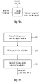
- the metadata converter is configured to apply a DirAC analysis to this pressure/velocity data as, for example, illustrated by the flowchart of Fig. 3c consisting of block 302, 304, 306.
- the DirAC parameters output by block 306 have a better quality than the DirAC parameters derived from the object metadata obtained by block 302, i.e., are enhanced DirAC parameters.
- Fig. 3b illustrates the conversion of a position for an object into the direction of arrival with respect to a reference position for the specific object.
- Fig. 3f illustrates a schematic diagram for explaining the functionality of the metadata converter 150.
- the metadata converter 150 receives the position of the object indicated by vector P in a coordinate system. Furthermore, the reference position, to which the DirAC metadata are to be related is given by vector R in the same coordinate system. Thus, the direction of arrival vector DoA extends from the tip of vector R to the tip of vector B. Thus, the actual DoA vector is obtained by subtracting the reference position R vector from the object position P vector.
- the vector difference is divided by the magnitude or length of the vector DoA.
- the length of the DoA vector can also be included into the metadata generated by the metadata converter 150 so that, additionally, the distance of the object from the reference point is also included in the metadata so that a selective manipulation of this object can also be performed based on the distance of the object from the reference position.
- the extract direction block 148 of Fig. 1f may also operate as discussed with respect to Fig. 3f , although other alternatives for calculating the DoA information and, optionally, the distance information can be applied as well.
- blocks 125 and 126 illustrated in Fig. 1c or 1d may operate in the similar way as discussed with respect to Fig. 3f .
- the Fig. 3a device may be configured to receive a plurality of audio object descriptions, and the metadata converter is configured to convert each metadata description directly into a DirAC description and, then, the metadata converter is configured to combine the individual DirAC metadata descriptions to obtain a combined DirAC description as the DirAC metadata illustrated in Fig. 3a .
- the combination is performed by calculating 320 a weighting factor for a first direction of arrival using a first energy and by calculating 322 a weighting factor for a second direction of arrival using a second energy, where the direction of arrival is processed by blocks 320, 332 related to the same time/frequency bin.
- a weighted addition is performed as also discussed with respect to item 144 in Fig. 1d .
- the procedure illustrated in Fig. 3a represents an embodiment of the first alternative Fig. 1d .
- the procedure would be that all diffuseness are set to zero or to a small value and, for a time/frequency bin, all different direction of arrival values that are given for this time/frequency bin are considered and the largest direction of arrival value is selected to be the combined direction of arrival value for this time/frequency bin.
- the second to largest value provided that the energy information for these two direction of arrival values are not so different.
- the direction of arrival value is selected whose energy is either the largest energy among the energies from the different contribution for this time frequency bin or the second or the third highest energy.
- the third aspect as described with respect to Figs. 3a to 3f are different from the first aspect in that the third aspect is also useful for the conversion of a single object description into a DirAC metadata.
- the input interface 100 may receive several object descriptions that are in the same object/metadata format.
- any format converter as discussed with respect to the first aspect in Fig. 1a is not required.
- the Fig. 3a embodiment may be useful in the context of receiving two different object descriptions using different object waveform signals and different object metadata as the first scene description and the second description as input into the format combiner 140, and the output of the metadata converter 150, 125, 126 or 148 may be a DirAC representation with DirAC metadata and, therefore, the DirAC analyzer 180 of Fig.
- the transport channel generator 160 corresponding to the downmixer 163 of Fig. 3a can be used in the context of the third aspect as well as the transport channel encoder 170, the metadata encoder 190 and, in this context, the output interface 300 of Fig. 3a corresponds to the output interface 200 of Fig. 1a .
- the output interface 300 of Fig. 3a corresponds to the output interface 200 of Fig. 1a .
- Figs. 4a, 4b illustrate a fourth aspect of the present invention in the context of an apparatus for performing a synthesis of audio data.
- the apparatus has an input interface 100 for receiving a DirAC description of an audio scene having DirAC metadata and additionally for receiving an object signal having object metadata.
- This audio scene encoder illustrated in Fig. 4b additionally comprises the metadata generator 400 for generating a combined metadata description comprising the DirAC metadata on the one hand and the object metadata on the other hand.
- the DirAC metadata comprises the direction of arrival for individual time/frequency tiles and the object metadata comprises a direction or additionally a distance or a diffuseness of an individual object.
- the input interface 100 is configured to receive, additionally, a transport signal associated with the DirAC description of the audio scene as illustrated in Fig. 4b , and the input interface is additionally configured for receiving an object waveform signal associated with the object signal. Therefore, the scene encoder further comprises a transport signal encoder for encoding the transport signal and the object waveform signal, and the transport encoder 170 may correspond to the encoder 170 of Fig. 1a .
- the metadata generator 140 that generates the combined metadata may be configured as discussed with respect to the first aspect, the second aspect or the third aspect.
- the metadata generator 400 is configured to generate, for the object metadata, a single broadband direction per time, i.e., for a certain time frame, and the metadata generator is configured to refresh the single broadband direction per time less frequently than the DirAC metadata.
- the fourth aspect of the present invention and, particularly, the metadata generator 400 represents a specific format converter where the common format is the DirAC format, and the input is a DirAC description for the first scene in the first format discussed with respect to Fig. 1a and the second scene is a single or a combined such as SAOC object signal.
- the output of the format converter 120 represents the output of the metadata generator 400 but, in contrast to an actual specific combination of the metadata by one of the two alternatives, for example, as discussed with respect to Fig. 1d , the object metadata is included in the output signal, i.e., the "combined metadata" separate from the metadata for the DirAC description to allow a selective modification for the object data.
- Fig. 2a represents a decoder-side implementation of the encoder illustrated in Fig. 4a, 4b with the provision that the decoder side of Fig. 2a device receives only a single DirAC description and the object metadata generated by the metadata generator 400 within the same bit stream as the "extra audio object metadata".
- the transport encoder 170 downmixes both data, i.e., the transport channel for the DirAC description and the waveform signal from the object, then the separation will be less perfect, but by means of additional object energy information, even a separation from a combined downmix channel and a selective modification of the object with respect to the DirAC description is available.
- Fig. 5a to 5d represent a further of fifth aspect of the invention in the context of an apparatus for performing a synthesis of audio data.
- an input interface 100 is provided for receiving a DirAC description of one or more audio objects and/or a DirAC description of a multi-channel signal and/or a DirAC description of a first order Ambisonics signal and/or a higher order Ambisonics signal, wherein the DirAC description comprises position information of the one or more objects or a side information for the first order Ambisonics signals or the high order Ambisonics signals or a position information for the multi-channel signal as side information or from a user interface.
- a manipulator 500 is configured for manipulating the DirAC description of the one or more audio objects, the DirAC description of the multi-channel signal, the DirAC description of the first order Ambisonics signals or the DirAC description of the high order Ambisonics signals to obtain a manipulated DirAC description.
- a DirAC synthesizer 220, 240 is configured for synthesizing this manipulated DirAC description to obtain synthesized audio data.
- the DirAC synthesizer 220, 240 comprises a DirAC renderer 222 as illustrated in Fig. 5b and the subsequently connected spectral-time converter 240 that outputs the manipulated time domain signal.
- the manipulator 500 is configured to perform a position-dependent weighting operation prior to DirAC rendering.
- the DirAC synthesizer when configured to output a plurality of objects of a first order Ambisonics signals or a high order Ambisonics signal or a multi-channel signal, the DirAC synthesizer is configured to use a separate spectral-time converter for each object or each component of the first or the high order Ambisonics signals or for each channel of the multichannel signal as illustrated in Fig. 5d at blocks 506, 508. As outlined in block 510 then the output of the corresponding separate conversions are added together provided that all the signals are in a common format, i.e., in compatible format.
- each representation could be manipulated separately as illustrated in block 502 in the parameter domain as already discussed with respect to Fig. 2b or 2c , and, then, a synthesis could be performed as outlined in block 504 for each manipulated description, and the synthesis could then be added in the time domain as discussed with respect to block 510 in Fig. 5d .
- the result of the individual DirAC synthesis procedures in the spectral domain could already be added in the spectral domain and then a single time domain conversion could be used as well.
- the manipulator 500 may be implemented as the manipulator discussed with respect to Fig. 2d or discussed with respect to any other aspect before.
- the fifth aspect of the present invention provides a significant feature with respect to the fact, when individual DirAC descriptions of very different sound signals are input, and when a certain manipulation of the individual descriptions is performed as discussed with respect to block 500 of Fig. 5a , where an input into the manipulator 500 may be a DirAC description of any format, including only a single format, while the second aspect was concentrating on the reception of at least two different DirAC descriptions or where the fourth aspect, for example, was related to the reception of a DirAC description on the one hand and an object signal description on the other hand.
- Fig. 6 illustrates another implementation for performing a synthesis different from the DirAC synthesizer.
- a sound field analyzer generates, for each source signal, a separate mono signal S and an original direction of arrival and when, depending on the translation information, a new direction of arrival is calculated
- the Ambisonics signal generator 430 of Fig. 6 would be used to generate a sound field description for the sound source signal, i.e., the mono signal S but for the new direction of arrival (DoA) data consisting of a horizontal angle ⁇ or an elevation angle ⁇ and an azimuth angle ⁇ .
- DoA new direction of arrival
- the Ambisonics signal generator 430 could be used, instead of the DirAC synthesizer 425, to generate, for each time/frequency bin, a full Ambisonics representation using the downmix signal or pressure signal or omnidirectional component for this time/frequency bin as the "mono signal S" of Fig. 6 . Then, an individual frequency-time conversion in frequency-time converter 426 for each of the W, X, Y, Z component would then result in a sound field description different from what is illustrated in Fig. 6 .
- Fig. 7a illustrates a DirAC analyzer as originally disclosed, for example, in the reference "Directional Audio Coding" from IWPASH of 2009.
- the DirAC analyzer comprises a bank of band filters 1310, an energy analyzer 1320, an intensity analyzer 1330, a temporal averaging block 1340 and a diffuseness calculator 1350 and the direction calculator 1360.
- DirAC both analysis and synthesis are performed in the frequency domain.
- the most commonly used frequency transforms include short time Fourier transform (STFT), and Quadrature mirror filter bank (QMF).
- STFT short time Fourier transform
- QMF Quadrature mirror filter bank
- the target of directional analysis is to estimate at each frequency band the direction of arrival of sound, together with an estimate if the sound is arriving from one or multiple directions at the same time. In principle, this can be performed with a number of techniques, however, the energetic analysis of sound field has been found to be suitable, which is illustrated in Fig. 7a .
- the energetic analysis can be performed, when the pressure signal and velocity signals in one, two or three dimensions are captured from a single position. In first-order B-format signals, the omnidirectional signal is called W-signal, which has been scaled down by the square root of two.
- the vector estimates the sound field velocity vector, and is also expressed in STFT domain.
- the energy E of the sound field is computed.
- the capturing of B-format signals can be obtained with either coincident positioning of directional microphones, or with a closely-spaced set of omnidirectional microphones. In some applications, the microphone signals may be formed in a computational domain, i.e., simulated.
- the direction of sound is defined to be the opposite direction of the intensity vector I. The direction is denoted as corresponding angular azimuth and elevation values in the transmitted metadata.
- the diffuseness of sound field is also computed using an expectation operator of the intensity vector and the energy.
- the outcome of this equation is a real-valued number between zero and one, characterizing if the sound energy is arriving from a single direction (diffuseness is zero), or from all directions (diffuseness is one). This procedure is appropriate in the case when the full 3D or less dimensional velocity information is available.
- Fig. 7b illustrates a DirAC synthesis, once again having a bank of band filters 1370, a virtual microphone block 1400, a direct/diffuse synthesizer block 1450, and a certain loudspeaker setup or a virtual intended loudspeaker setup 1460. Additionally, a diffuseness-gain transformer 1380, a vector based amplitude panning (VBAP) gain table block 1390, a microphone compensation block 1420, a loudspeaker gain averaging block 1430 and a distributer 1440 for other channels is used.
- VBAP vector based amplitude panning
- the 7b receives all B-format signals, for which a virtual microphone signal is computed for each loudspeaker direction of the loudspeaker setup 1460.
- the utilized directional pattern is typically a dipole.
- the virtual microphone signals are then modified in non-linear fashion, depending on the metadata.
- the low bitrate version of DirAC is not shown in Fig. 7b , however, in this situation, only one channel of audio is transmitted as illustrated in Fig. 6 .
- the difference in processing is that all virtual microphone signals would be replaced by the single channel of audio received.
- the virtual microphone signals are divided into two streams: the diffuse and the non-diffuse streams, which are processed separately.
- the non-diffuse sound is reproduced as point sources by using vector base amplitude panning (VBAP).
- panning a monophonic sound signal is applied to a subset of loudspeakers after multiplication with loudspeaker-specific gain factors.
- the gain factors are computed using the information of a loudspeaker setup, and specified panning direction.
- the input signal is simply panned to the directions implied by the metadata.
- each virtual microphone signal is multiplied with the corresponding gain factor, which produces the same effect with panning, however it is less prone to any non-linear artifacts.
- the directional metadata is subject to abrupt temporal changes.
- the gain factors for loudspeakers computed with VBAP are smoothed by temporal integration with frequency-dependent time constants equaling to about 50 cycle periods at each band. This effectively removes the artifacts, however, the changes in direction are not perceived to be slower than without averaging in most of the cases.
- the aim of the synthesis of the diffuse sound is to create perception of sound that surrounds the listener.
- the diffuse stream is reproduced by decorrelating the input signal and reproducing it from every loudspeaker.
- the virtual microphone signals of diffuse stream are already incoherent in some degree, and they need to be decorrelated only mildly.
- DirAC is formulated with a certain amount of virtual loudspeakers around the listener for the non-diffuse stream and a certain number of loudspeakers for the diffuse steam.
- the virtual loudspeakers are implemented as convolution of input signals with a measured head-related transfer functions (HRTFs).
- the present invention refers to the combination of different scenes in different formats using a common format, where the common format may, for example, be the B-format domain, the pressure/velocity domain or the metadata domain as discussed, for example, in items 120, 140 of Fig. 1a .
- a DirAC analysis 802 is performed in one alternative before the transmission in the encoder as discussed before with respect to item 180 of Fig. 1a .
- the result is encoded as discussed before with respect to the encoder 170 and the metadata encoder 190 and the encoded result is transmitted via the encoded output signal generated by the output interface 200.
- the result could be directly rendered by a Fig. 1a device when the output of block 160 of Fig. 1a and the output of block 180 of Fig. 1a is forwarded to a DirAC renderer.
- the Fig. 1a device would not be a specific encoder device but would be an analyzer and a corresponding renderer.
- FIG. 8 A further alternative is illustrated in the right branch of Fig. 8 , where a transmission from the encoder to the decoder is performed and, as illustrated in block 804, the DirAC analysis and the DirAC synthesis are performed subsequent to the transmission, i.e., at a decoder-side.
- This procedure would be the case, when the alternative of Fig. 1a is used, i.e., that the encoded output signal is a B-format signal without spatial metadata.
- the result could be rendered for replay or, alternatively, the result could even be encoded and again transmitted.
- a Dirac-based spatial audio coder that can encode multi-channel signals, Ambisonics formats and audio objects separately or simultaneously.
- the second aspect of the invention is related to the combination and rendering two or more DirAC descriptions in the spectral domain.
- the third aspect of the invention is related to the conversion of object metadata and optionally object waveform signals directly into the DirAC domain and in an embodiment the combination of several objects into an object representation.
- the third aspect of the invention addresses the amendment of the DirAC metadata with the directions and, optimally, the distance or diffuseness of the individual objects composing the combined audio scene represented by the DirAC parameters.
- This extra information is easily coded, since it consist mainly of a single broadband direction per time unit and can be refreshed less frequently than the other DirAC parameters since objects can be assumed to be either static or moving at a slow pace.
- the fourth aspect is related to the decoder side and exploits the known positions of audio objects.
- the positions can be given by the user though an interactive interface and can also be included as extra side-information within the bitstream.
- the aim is to be able to manipulate an output audio scene comprising a number of objects by individually changing the objects' attributes such as levels, equalization and/or spatial positions. It can also be envisioned to filter completely the object or restitute individual objects from the combined stream.
- the manipulation of the output audio scene can be achieved by jointly processing the spatial parameters of the DirAC metadata, the objects' metadata, interactive user input if present and the audio signals carried in the transport channels.
- the present invention provides, in further embodiments, and particularly with respect to the first aspect and also with respect to the other aspects different alternatives. These alternatives are the following:
- An inventively encoded audio signal can be stored on a digital storage medium or a non-transitory storage medium or can be transmitted on a transmission medium such as a wireless transmission medium or a wired transmission medium such as the Internet.
- aspects have been described in the context of an apparatus, it is clear that these aspects also represent a description of the corresponding method, where a block or device corresponds to a method step or a feature of a method step. Analogously, aspects described in the context of a method step also represent a description of a corresponding block or item or feature of a corresponding apparatus.
- embodiments of the invention can be implemented in hardware or in software.
- the implementation can be performed using a digital storage medium, for example a floppy disk, a DVD, a CD, a ROM, a PROM, an EPROM, an EEPROM or a FLASH memory, having electronically readable control signals stored thereon, which cooperate (or are capable of cooperating) with a programmable computer system such that the respective method is performed.
- a digital storage medium for example a floppy disk, a DVD, a CD, a ROM, a PROM, an EPROM, an EEPROM or a FLASH memory, having electronically readable control signals stored thereon, which cooperate (or are capable of cooperating) with a programmable computer system such that the respective method is performed.
- Some embodiments according to the invention comprise a data carrier having electronically readable control signals, which are capable of cooperating with a programmable computer system, such that one of the methods described herein is performed.
- embodiments of the present invention can be implemented as a computer program product with a program code, the program code being operative for performing one of the methods when the computer program product runs on a computer.
- the program code may for example be stored on a machine readable carrier.
- inventions comprise the computer program for performing one of the methods described herein, stored on a machine readable carrier or a non-transitory storage medium.
- an embodiment of the inventive method is, therefore, a computer program having a program code for performing one of the methods described herein, when the computer program runs on a computer.
- a further embodiment of the inventive methods is, therefore, a data carrier (or a digital storage medium, or a computer-readable medium) comprising, recorded thereon, the computer program for performing one of the methods described herein.
- a further embodiment of the inventive method is, therefore, a data stream or a sequence of signals representing the computer program for performing one of the methods described herein.
- the data stream or the sequence of signals may for example be configured to be transferred via a data communication connection, for example via the Internet.
- a further embodiment comprises a processing means, for example a computer, or a programmable logic device, configured to or adapted to perform one of the methods described herein.
- a processing means for example a computer, or a programmable logic device, configured to or adapted to perform one of the methods described herein.
- a further embodiment comprises a computer having installed thereon the computer program for performing one of the methods described herein.
- a programmable logic device for example a field programmable gate array
- a field programmable gate array may cooperate with a microprocessor in order to perform one of the methods described herein.
- the methods are preferably performed by any hardware apparatus.
Landscapes
- Engineering & Computer Science (AREA)
- Physics & Mathematics (AREA)
- Signal Processing (AREA)
- Acoustics & Sound (AREA)
- Audiology, Speech & Language Pathology (AREA)
- Health & Medical Sciences (AREA)
- Computational Linguistics (AREA)
- Human Computer Interaction (AREA)
- Multimedia (AREA)
- Mathematical Physics (AREA)
- Stereophonic System (AREA)
- Compression, Expansion, Code Conversion, And Decoders (AREA)
- Signal Processing For Digital Recording And Reproducing (AREA)
Applications Claiming Priority (3)
| Application Number | Priority Date | Filing Date | Title |
|---|---|---|---|
| EP17194816 | 2017-10-04 | ||
| EP18779381.5A EP3692523B1 (de) | 2017-10-04 | 2018-10-01 | Vorrichtung, verfahren und computerprogramm zur codierung, decodierung, szenenverarbeitung und für andere verfahren im zusammenhang mit einer dirac-basierten räumlichen audiocodierung |
| PCT/EP2018/076641 WO2019068638A1 (en) | 2017-10-04 | 2018-10-01 | APPARATUS, METHOD AND COMPUTER PROGRAM FOR CODING, DECODING, SCENE PROCESSING AND OTHER PROCEDURES RELATED TO DIRAC-BASED SPATIAL AUDIO CODING |
Related Parent Applications (2)
| Application Number | Title | Priority Date | Filing Date |
|---|---|---|---|
| EP18779381.5A Division-Into EP3692523B1 (de) | 2017-10-04 | 2018-10-01 | Vorrichtung, verfahren und computerprogramm zur codierung, decodierung, szenenverarbeitung und für andere verfahren im zusammenhang mit einer dirac-basierten räumlichen audiocodierung |
| EP18779381.5A Division EP3692523B1 (de) | 2017-10-04 | 2018-10-01 | Vorrichtung, verfahren und computerprogramm zur codierung, decodierung, szenenverarbeitung und für andere verfahren im zusammenhang mit einer dirac-basierten räumlichen audiocodierung |
Publications (2)
| Publication Number | Publication Date |
|---|---|
| EP3975176A2 true EP3975176A2 (de) | 2022-03-30 |
| EP3975176A3 EP3975176A3 (de) | 2022-07-27 |
Family
ID=60185972
Family Applications (2)
| Application Number | Title | Priority Date | Filing Date |
|---|---|---|---|
| EP21208008.9A Pending EP3975176A3 (de) | 2017-10-04 | 2018-10-01 | Vorrichtung, verfahren und computerprogramm zur codierung, szenenverarbeitung und für andere verfahren im zusammenhang mit einer dirac-basierten räumlichen audiocodierung |
| EP18779381.5A Active EP3692523B1 (de) | 2017-10-04 | 2018-10-01 | Vorrichtung, verfahren und computerprogramm zur codierung, decodierung, szenenverarbeitung und für andere verfahren im zusammenhang mit einer dirac-basierten räumlichen audiocodierung |
Family Applications After (1)
| Application Number | Title | Priority Date | Filing Date |
|---|---|---|---|
| EP18779381.5A Active EP3692523B1 (de) | 2017-10-04 | 2018-10-01 | Vorrichtung, verfahren und computerprogramm zur codierung, decodierung, szenenverarbeitung und für andere verfahren im zusammenhang mit einer dirac-basierten räumlichen audiocodierung |
Country Status (18)
| Country | Link |
|---|---|
| US (3) | US11368790B2 (de) |
| EP (2) | EP3975176A3 (de) |
| JP (2) | JP7297740B2 (de) |
| KR (2) | KR102468780B1 (de) |
| CN (2) | CN111630592B (de) |
| AR (2) | AR117384A1 (de) |
| AU (2) | AU2018344830B2 (de) |
| BR (1) | BR112020007486A2 (de) |
| CA (4) | CA3219540A1 (de) |
| ES (1) | ES2907377T3 (de) |
| MX (1) | MX2020003506A (de) |
| PL (1) | PL3692523T3 (de) |
| PT (1) | PT3692523T (de) |
| RU (1) | RU2759160C2 (de) |
| SG (1) | SG11202003125SA (de) |
| TW (1) | TWI700687B (de) |
| WO (1) | WO2019068638A1 (de) |
| ZA (1) | ZA202001726B (de) |
Families Citing this family (13)
| Publication number | Priority date | Publication date | Assignee | Title |
|---|---|---|---|---|
| WO2019204214A2 (en) | 2018-04-16 | 2019-10-24 | Dolby Laboratories Licensing Corporation | Methods, apparatus and systems for encoding and decoding of directional sound sources |
| EP3818524B1 (de) * | 2018-07-02 | 2023-12-13 | Dolby Laboratories Licensing Corporation | Verfahren und vorrichtungen zur erzeugung oder decodierung eines bitstroms mit immersiven audiosignalen |
| US11765536B2 (en) | 2018-11-13 | 2023-09-19 | Dolby Laboratories Licensing Corporation | Representing spatial audio by means of an audio signal and associated metadata |
| BR112021010972A2 (pt) * | 2018-12-07 | 2021-09-08 | Fraunhofer-Gesellschaft zur Förderung der angewandten Forschung e.V. | Aparelho e método para gerar uma descrição de campo de som |
| US11158335B1 (en) * | 2019-03-28 | 2021-10-26 | Amazon Technologies, Inc. | Audio beam selection |
| WO2020217781A1 (ja) | 2019-04-24 | 2020-10-29 | パナソニック インテレクチュアル プロパティ コーポレーション オブ アメリカ | 到来方向推定装置、システム、及び、到来方向推定方法 |
| GB2587335A (en) * | 2019-09-17 | 2021-03-31 | Nokia Technologies Oy | Direction estimation enhancement for parametric spatial audio capture using broadband estimates |
| US11430451B2 (en) * | 2019-09-26 | 2022-08-30 | Apple Inc. | Layered coding of audio with discrete objects |
| CN114616621A (zh) * | 2019-10-30 | 2022-06-10 | 杜比实验室特许公司 | 在浸入式语音及音频服务中的位速率分布 |
| TWI825492B (zh) * | 2020-10-13 | 2023-12-11 | 弗勞恩霍夫爾協會 | 對多個音頻對象進行編碼的設備和方法、使用兩個以上之相關音頻對象進行解碼的設備和方法、電腦程式及資料結構產品 |
| WO2022079044A1 (en) | 2020-10-13 | 2022-04-21 | Fraunhofer-Gesellschaft zur Förderung der angewandten Forschung e.V. | Apparatus and method for encoding a plurality of audio objects using direction information during a downmixing or apparatus and method for decoding using an optimized covariance synthesis |
| GB2608406A (en) * | 2021-06-30 | 2023-01-04 | Nokia Technologies Oy | Creating spatial audio stream from audio objects with spatial extent |
| WO2024069796A1 (ja) * | 2022-09-28 | 2024-04-04 | 三菱電機株式会社 | 音空間構築装置、音空間構築システム、プログラム及び音空間構築方法 |
Citations (1)
| Publication number | Priority date | Publication date | Assignee | Title |
|---|---|---|---|---|
| US9015051B2 (en) | 2007-03-21 | 2015-04-21 | Fraunhofer-Gesellschaft Zur Foerderung Der Angewandten Forschung E.V. | Reconstruction of audio channels with direction parameters indicating direction of origin |
Family Cites Families (26)
| Publication number | Priority date | Publication date | Assignee | Title |
|---|---|---|---|---|
| TW432806B (en) * | 1996-12-09 | 2001-05-01 | Matsushita Electric Ind Co Ltd | Audio decoding device |
| US8872979B2 (en) | 2002-05-21 | 2014-10-28 | Avaya Inc. | Combined-media scene tracking for audio-video summarization |
| TW200742359A (en) * | 2006-04-28 | 2007-11-01 | Compal Electronics Inc | Internet communication system |
| US9014377B2 (en) * | 2006-05-17 | 2015-04-21 | Creative Technology Ltd | Multichannel surround format conversion and generalized upmix |
| US20080004729A1 (en) * | 2006-06-30 | 2008-01-03 | Nokia Corporation | Direct encoding into a directional audio coding format |
| US8290167B2 (en) * | 2007-03-21 | 2012-10-16 | Fraunhofer-Gesellschaft Zur Foerderung Der Angewandten Forschung E.V. | Method and apparatus for conversion between multi-channel audio formats |
| US8509454B2 (en) | 2007-11-01 | 2013-08-13 | Nokia Corporation | Focusing on a portion of an audio scene for an audio signal |
| WO2009109217A1 (en) * | 2008-03-03 | 2009-09-11 | Nokia Corporation | Apparatus for capturing and rendering a plurality of audio channels |
| EP2154911A1 (de) * | 2008-08-13 | 2010-02-17 | Fraunhofer-Gesellschaft zur Förderung der angewandten Forschung e.V. | Vorrichtung zur Bestimmung eines räumlichen Mehrkanalausgangsaudiosignals |
| EP2154910A1 (de) * | 2008-08-13 | 2010-02-17 | Fraunhofer-Gesellschaft zur Förderung der angewandten Forschung e.V. | Vorrichtung zum Mischen von Raumtonströmen |
| PL2154677T3 (pl) * | 2008-08-13 | 2013-12-31 | Fraunhofer Ges Forschung | Urządzenie do wyznaczania konwertowanego przestrzennego sygnału audio |
| CN102016982B (zh) * | 2009-02-04 | 2014-08-27 | 松下电器产业株式会社 | 结合装置、远程通信系统以及结合方法 |
| EP2249334A1 (de) * | 2009-05-08 | 2010-11-10 | Fraunhofer-Gesellschaft zur Förderung der angewandten Forschung e.V. | Audioformat-Transkodierer |
| WO2011104418A1 (en) * | 2010-02-26 | 2011-09-01 | Nokia Corporation | Modifying spatial image of a plurality of audio signals |
| DE102010030534A1 (de) * | 2010-06-25 | 2011-12-29 | Iosono Gmbh | Vorrichtung zum Veränderung einer Audio-Szene und Vorrichtung zum Erzeugen einer Richtungsfunktion |
| EP2448289A1 (de) | 2010-10-28 | 2012-05-02 | Fraunhofer-Gesellschaft zur Förderung der angewandten Forschung e.V. | Vorrichtung und Verfahren zur Ableitung einer direktionalen Information und Systeme |
| EP2464145A1 (de) | 2010-12-10 | 2012-06-13 | Fraunhofer-Gesellschaft zur Förderung der angewandten Forschung e.V. | Vorrichtung und Verfahren zur Dekomposition eines Eingabesignals mit einem Downmixer |
| EP2600343A1 (de) * | 2011-12-02 | 2013-06-05 | Fraunhofer-Gesellschaft zur Förderung der angewandten Forschung e.V. | Vorrichtung und Verfahren zum Mischen von Raumtoncodierungsstreams auf Geometriebasis |
| WO2013156818A1 (en) * | 2012-04-19 | 2013-10-24 | Nokia Corporation | An audio scene apparatus |
| US9190065B2 (en) * | 2012-07-15 | 2015-11-17 | Qualcomm Incorporated | Systems, methods, apparatus, and computer-readable media for three-dimensional audio coding using basis function coefficients |
| CN103236255A (zh) * | 2013-04-03 | 2013-08-07 | 广西环球音乐图书有限公司 | 音频文件转化midi文件 |
| DE102013105375A1 (de) | 2013-05-24 | 2014-11-27 | Fraunhofer-Gesellschaft zur Förderung der angewandten Forschung e.V. | Tonsignalerzeuger, Verfahren und Computerprogramm zum Bereitstellen eines Tonsignals |
| US9847088B2 (en) * | 2014-08-29 | 2017-12-19 | Qualcomm Incorporated | Intermediate compression for higher order ambisonic audio data |
| KR101993348B1 (ko) * | 2014-09-24 | 2019-06-26 | 한국전자통신연구원 | 동적 포맷 변환을 지원하는 오디오 메타데이터 제공 장치 및 오디오 데이터 재생 장치, 상기 장치가 수행하는 방법 그리고 상기 동적 포맷 변환들이 기록된 컴퓨터에서 판독 가능한 기록매체 |
| KR102516625B1 (ko) | 2015-01-30 | 2023-03-30 | 디티에스, 인코포레이티드 | 몰입형 오디오를 캡처하고, 인코딩하고, 분산하고, 디코딩하기 위한 시스템 및 방법 |
| CN104768053A (zh) | 2015-04-15 | 2015-07-08 | 冯山泉 | 一种基于流分解和流重组的格式转换方法及系统 |
-
2018
- 2018-10-01 ES ES18779381T patent/ES2907377T3/es active Active
- 2018-10-01 PL PL18779381T patent/PL3692523T3/pl unknown
- 2018-10-01 CA CA3219540A patent/CA3219540A1/en active Pending
- 2018-10-01 EP EP21208008.9A patent/EP3975176A3/de active Pending
- 2018-10-01 WO PCT/EP2018/076641 patent/WO2019068638A1/en unknown
- 2018-10-01 PT PT187793815T patent/PT3692523T/pt unknown
- 2018-10-01 CA CA3134343A patent/CA3134343A1/en active Pending
- 2018-10-01 JP JP2020519284A patent/JP7297740B2/ja active Active
- 2018-10-01 EP EP18779381.5A patent/EP3692523B1/de active Active
- 2018-10-01 KR KR1020207012249A patent/KR102468780B1/ko active IP Right Grant
- 2018-10-01 KR KR1020227032462A patent/KR20220133311A/ko not_active Application Discontinuation
- 2018-10-01 RU RU2020115048A patent/RU2759160C2/ru active
- 2018-10-01 MX MX2020003506A patent/MX2020003506A/es unknown
- 2018-10-01 SG SG11202003125SA patent/SG11202003125SA/en unknown
- 2018-10-01 CN CN201880077928.6A patent/CN111630592B/zh active Active
- 2018-10-01 CN CN202311301426.6A patent/CN117395593A/zh active Pending
- 2018-10-01 BR BR112020007486-1A patent/BR112020007486A2/pt unknown
- 2018-10-01 CA CA3219566A patent/CA3219566A1/en active Pending
- 2018-10-01 CA CA3076703A patent/CA3076703C/en active Active
- 2018-10-01 AU AU2018344830A patent/AU2018344830B2/en active Active
- 2018-10-03 TW TW107134948A patent/TWI700687B/zh active
- 2018-10-04 AR ARP180102867A patent/AR117384A1/es active IP Right Grant
-
2020
- 2020-03-17 US US16/821,069 patent/US11368790B2/en active Active
- 2020-03-18 ZA ZA2020/01726A patent/ZA202001726B/en unknown
-
2021
- 2021-12-23 AU AU2021290361A patent/AU2021290361B2/en active Active
-
2022
- 2022-01-26 US US17/585,169 patent/US20220150635A1/en active Pending
- 2022-01-26 US US17/585,124 patent/US11729554B2/en active Active
- 2022-03-21 AR ARP220100655A patent/AR125562A2/es unknown
-
2023
- 2023-06-14 JP JP2023098016A patent/JP2023126225A/ja active Pending
Patent Citations (1)
| Publication number | Priority date | Publication date | Assignee | Title |
|---|---|---|---|---|
| US9015051B2 (en) | 2007-03-21 | 2015-04-21 | Fraunhofer-Gesellschaft Zur Foerderung Der Angewandten Forschung E.V. | Reconstruction of audio channels with direction parameters indicating direction of origin |
Non-Patent Citations (6)
| Title |
|---|
| DANIEL P. JARRETTOLIVER THIERGARTEMANUEL A. P. HABETSPATRICK A. NAYLOR: "Coherence-Based Diffuseness Estimation in the Spherical Harmonic Domain", IEEE 27TH CONVENTION OF ELECTRICAL AND ELECTRONICS ENGINEERS IN ISRAEL (IEEEI, 2012 |
| G. DEL GALDOF. KUECHM. KALLINGERR. SCHULTZ-AMLING: "Efficient merging of multiple audio streams for spatial sound reproduction in Directional Audio Coding", 2009 IEEE INTERNATIONAL CONFERENCE ON ACOUSTICS, SPEECH AND SIGNAL PROCESSING, TAIPEI, 2009, pages 265 - 268, XP031459217 |
| JURGEN HERRECORNELIA FALCHDIRK MAHNEGIOVANNI DEL GALDOMARKUS KALLINGEROLIVER THIERGART: "Interactive Teleconferencing Combining Spatial Audio Object Coding and DirAC Technology", J. AUDIO ENG. SOC., vol. 59, no. 12, December 2011 (2011-12-01), XP040574482 |
| M. V. LAITINENV. PULKKI: "Converting 5.1 audio recordings to B-format for directional audio coding reproduction", 2011 IEEE INTERNATIONAL CONFERENCE ON ACOUSTICS, SPEECH AND SIGNAL PROCESSING (ICASSP), PRAGUE, 2011, pages 61 - 64, XP032000663, DOI: 10.1109/ICASSP.2011.5946328 |
| R. SCHULTZ-AMLINGF. KUECHM. KALLINGERG. DEL GALDOJ. AHONENV. PULKKI: "Planar Microphone Array Processing for the Analysis and Reproduction of Spatial Audio using Directional Audio Coding", AUDIO ENGINEERING SOCIETY CONVENTION 124, AMSTERDAM, THE NETHERLANDS, 2008 |
| VILLE PULKKI: "Virtual source positioning using vector base amplitude panning", J. AUDIO ENG. SOC., vol. 45, no. 6, June 1997 (1997-06-01), pages 456 - 466 |
Also Published As
Similar Documents
| Publication | Publication Date | Title |
|---|---|---|
| EP3692523B1 (de) | Vorrichtung, verfahren und computerprogramm zur codierung, decodierung, szenenverarbeitung und für andere verfahren im zusammenhang mit einer dirac-basierten räumlichen audiocodierung | |
| US8611550B2 (en) | Apparatus for determining a converted spatial audio signal | |
| US20200145776A1 (en) | Concept for generating an enhanced sound-field description or a modified sound field description using a multi-layer description | |
| JP2022518744A (ja) | 空間オーディオ表現を符号化するための装置および方法、またはトランスポートメタデータを使用して符号化されたオーディオ信号を復号するための装置および方法、ならびに関連するコンピュータプログラム | |
| JP7311602B2 (ja) | 低次、中次、高次成分生成器を用いたDirACベースの空間音声符号化に関する符号化、復号化、シーン処理および他の手順を行う装置、方法およびコンピュータプログラム | |
| WO2015145782A1 (en) | Apparatus and method for surround audio signal processing | |
| CN115580822A (zh) | 空间音频捕获、传输和再现 | |
| EP3984027B1 (de) | Paketverlustverdeckung für dirac-basierte räumliche audiocodierung | |
| TWI834760B (zh) | 用於編碼、解碼、場景處理及與以指向性音訊編碼為基礎之空間音訊編碼有關的其他程序之裝置、方法及電腦程式 | |
| CN112133316A (zh) | 空间音频表示和渲染 | |
| JP2023548650A (ja) | 帯域幅拡張を用いて符号化されたオーディオシーンを処理するための装置、方法、またはコンピュータプログラム | |
| JP2023549033A (ja) | パラメータ平滑化を用いて符号化されたオーディオシーンを処理するための装置、方法、またはコンピュータプログラム |
Legal Events
| Date | Code | Title | Description |
|---|---|---|---|
| PUAI | Public reference made under article 153(3) epc to a published international application that has entered the european phase |
Free format text: ORIGINAL CODE: 0009012 |
|
| STAA | Information on the status of an ep patent application or granted ep patent |
Free format text: STATUS: THE APPLICATION HAS BEEN PUBLISHED |
|
| AC | Divisional application: reference to earlier application |
Ref document number: 3692523 Country of ref document: EP Kind code of ref document: P |
|
| AK | Designated contracting states |
Kind code of ref document: A2 Designated state(s): AL AT BE BG CH CY CZ DE DK EE ES FI FR GB GR HR HU IE IS IT LI LT LU LV MC MK MT NL NO PL PT RO RS SE SI SK SM TR |
|
| RAP3 | Party data changed (applicant data changed or rights of an application transferred) |
Owner name: FRAUNHOFER-GESELLSCHAFT ZUR FOERDERUNG DER ANGEWANDTEN FORSCHUNG E.V. |
|
| PUAL | Search report despatched |
Free format text: ORIGINAL CODE: 0009013 |
|
| AK | Designated contracting states |
Kind code of ref document: A3 Designated state(s): AL AT BE BG CH CY CZ DE DK EE ES FI FR GB GR HR HU IE IS IT LI LT LU LV MC MK MT NL NO PL PT RO RS SE SI SK SM TR |
|
| RIC1 | Information provided on ipc code assigned before grant |
Ipc: G10L 19/16 20130101ALI20220621BHEP Ipc: G10L 19/008 20130101AFI20220621BHEP |
|
| STAA | Information on the status of an ep patent application or granted ep patent |
Free format text: STATUS: REQUEST FOR EXAMINATION WAS MADE |
|
| 17P | Request for examination filed |
Effective date: 20230127 |
|
| RBV | Designated contracting states (corrected) |
Designated state(s): AL AT BE BG CH CY CZ DE DK EE ES FI FR GB GR HR HU IE IS IT LI LT LU LV MC MK MT NL NO PL PT RO RS SE SI SK SM TR |