EP3340648A1 - Verarbeitung von audiosignalen - Google Patents
Verarbeitung von audiosignalen Download PDFInfo
- Publication number
- EP3340648A1 EP3340648A1 EP16206555.1A EP16206555A EP3340648A1 EP 3340648 A1 EP3340648 A1 EP 3340648A1 EP 16206555 A EP16206555 A EP 16206555A EP 3340648 A1 EP3340648 A1 EP 3340648A1
- Authority
- EP
- European Patent Office
- Prior art keywords
- signal
- sound sources
- location
- audio signal
- rotated
- Prior art date
- Legal status (The legal status is an assumption and is not a legal conclusion. Google has not performed a legal analysis and makes no representation as to the accuracy of the status listed.)
- Granted
Links
- 230000005236 sound signal Effects 0.000 title claims abstract description 69
- 238000012545 processing Methods 0.000 title claims abstract description 15
- 238000000034 method Methods 0.000 claims abstract description 49
- 230000001419 dependent effect Effects 0.000 claims abstract description 4
- 239000011159 matrix material Substances 0.000 claims description 29
- 230000001131 transforming effect Effects 0.000 claims description 6
- 238000004590 computer program Methods 0.000 claims description 5
- 238000010586 diagram Methods 0.000 description 11
- 230000006870 function Effects 0.000 description 11
- 238000012546 transfer Methods 0.000 description 6
- 238000013459 approach Methods 0.000 description 4
- 230000003190 augmentative effect Effects 0.000 description 4
- 230000004807 localization Effects 0.000 description 4
- 238000012880 independent component analysis Methods 0.000 description 2
- 238000012986 modification Methods 0.000 description 2
- 230000004048 modification Effects 0.000 description 2
- 230000001052 transient effect Effects 0.000 description 2
- 230000000007 visual effect Effects 0.000 description 2
- 230000000694 effects Effects 0.000 description 1
- 238000004519 manufacturing process Methods 0.000 description 1
- 230000003278 mimic effect Effects 0.000 description 1
- 238000012805 post-processing Methods 0.000 description 1
- 230000006798 recombination Effects 0.000 description 1
- 238000005215 recombination Methods 0.000 description 1
- 238000000926 separation method Methods 0.000 description 1
Images


Classifications
-
- H—ELECTRICITY
- H04—ELECTRIC COMMUNICATION TECHNIQUE
- H04S—STEREOPHONIC SYSTEMS
- H04S7/00—Indicating arrangements; Control arrangements, e.g. balance control
- H04S7/30—Control circuits for electronic adaptation of the sound field
- H04S7/302—Electronic adaptation of stereophonic sound system to listener position or orientation
- H04S7/303—Tracking of listener position or orientation
-
- H—ELECTRICITY
- H04—ELECTRIC COMMUNICATION TECHNIQUE
- H04M—TELEPHONIC COMMUNICATION
- H04M3/00—Automatic or semi-automatic exchanges
- H04M3/42—Systems providing special services or facilities to subscribers
- H04M3/56—Arrangements for connecting several subscribers to a common circuit, i.e. affording conference facilities
- H04M3/568—Arrangements for connecting several subscribers to a common circuit, i.e. affording conference facilities audio processing specific to telephonic conferencing, e.g. spatial distribution, mixing of participants
-
- H—ELECTRICITY
- H04—ELECTRIC COMMUNICATION TECHNIQUE
- H04R—LOUDSPEAKERS, MICROPHONES, GRAMOPHONE PICK-UPS OR LIKE ACOUSTIC ELECTROMECHANICAL TRANSDUCERS; DEAF-AID SETS; PUBLIC ADDRESS SYSTEMS
- H04R1/00—Details of transducers, loudspeakers or microphones
- H04R1/20—Arrangements for obtaining desired frequency or directional characteristics
- H04R1/32—Arrangements for obtaining desired frequency or directional characteristics for obtaining desired directional characteristic only
- H04R1/40—Arrangements for obtaining desired frequency or directional characteristics for obtaining desired directional characteristic only by combining a number of identical transducers
- H04R1/406—Arrangements for obtaining desired frequency or directional characteristics for obtaining desired directional characteristic only by combining a number of identical transducers microphones
-
- H—ELECTRICITY
- H04—ELECTRIC COMMUNICATION TECHNIQUE
- H04S—STEREOPHONIC SYSTEMS
- H04S2400/00—Details of stereophonic systems covered by H04S but not provided for in its groups
- H04S2400/01—Multi-channel, i.e. more than two input channels, sound reproduction with two speakers wherein the multi-channel information is substantially preserved
-
- H—ELECTRICITY
- H04—ELECTRIC COMMUNICATION TECHNIQUE
- H04S—STEREOPHONIC SYSTEMS
- H04S2400/00—Details of stereophonic systems covered by H04S but not provided for in its groups
- H04S2400/15—Aspects of sound capture and related signal processing for recording or reproduction
-
- H—ELECTRICITY
- H04—ELECTRIC COMMUNICATION TECHNIQUE
- H04S—STEREOPHONIC SYSTEMS
- H04S2420/00—Techniques used stereophonic systems covered by H04S but not provided for in its groups
- H04S2420/01—Enhancing the perception of the sound image or of the spatial distribution using head related transfer functions [HRTF's] or equivalents thereof, e.g. interaural time difference [ITD] or interaural level difference [ILD]
Definitions
- the disclosure relates to processing multi-channel audio signals.
- Audio rotation is particularly useful for virtual/augmented reality applications.
- a user of a VR or AR device rotates their head, the displayed video rotates to match the user's movements.
- a more accurate impression of moving in the real world can be achieved if the sounds played to the user also seem to rotate with the user.
- the position of a person talking should appear to rotate when a listener rotates their head.
- a method of processing a multi-channel audio signal comprising the steps of:
- the step of determining the location of sound sources may comprise classifying sound sources as located in a first region or a second region relative to a recording device.
- the first region may be in front of the recording device and the second region may be behind the recording device.
- the step of applying a rotation operation to the signal may comprise:
- the step of generating a rotated audio signal may comprise combining the rotated first signal with the rotated second signal to form the rotated audio signal.
- the first and second rotation operations may rotate signals in opposite directions by the same rotation angle.
- the step of determining the location of sound sources may comprise determining the location of each of a plurality of sound sources within the audio signal.
- the step of determining the location of sound sources may further comprise determining a direction of arrival of each sound source at the recording device.
- the step of applying a rotation operation may comprise:
- the method may further comprise transforming the audio signal into the frequency domain, wherein the step of generating a rotated audio signal comprises transforming the signal into the time domain after the rotation operation has been applied to the signal.
- Other transforms may alternatively be applied, such as a wavelet transform.
- the step of determining a location of sound sources within the signal may comprise estimating the location of the sound sources using a regression algorithm.
- the step of determining a location of sound sources within the signal may comprise comparing the signal to pre-determined calibration information associated with the recording device. This may be done by establishing the location of sound sources by determining the values of s for which the function
- an audio processing device comprising:
- a computer program comprising instructions for causing a processor to perform the method according to the first aspect.
- the computer program may be a software implementation, and the computer may be considered as any appropriate hardware, including a digital signal processor, a microcontroller, and an implementation in read only memory (ROM), erasable programmable read only memory (EPROM) or electronically erasable programmable read only memory (EEPROM), as nonlimiting examples.
- the software implementation may be an assembly program.
- the computer program may be provided on a computer readable medium, which may be a physical computer readable medium, such as a disc or a memory device, or may be embodied as a transient signal.
- a transient signal may be a network download, including an internet download.
- a recording device 100 makes an audio recording comprising two sound sources (or, in the illustrated example, speakers), source 101 and source 102.
- the recording device 100 comprises two microphones 103, 104, so that two-channel audio can be recorded.
- the recording device 100 also comprises a camera 105 for visual recording.
- both sources 101 and 102 are located within the same half of a two dimensional plane around the recording device 100.
- the direction of arrival (DOA) of sound from sources 101, 102 at the recording device 100 lies within the azimuth range of 0-180° (referred to as "in front" of the device 100 below).
- An origin for measuring angles may be defined by a line 106 passing through the centre the microphones 103, 104.
- source 101 is located at an angle of 90° relative to the zero degree line or origin 106, and source 102 is located at 0°.
- the recorded audio may be played back to a listener, for example using a VR device.
- the video recording from camera 103 may also be played to the user. If the user rotates their head by an angle ⁇ , the video and audio should rotate by an equal angle to match the user's movements.
- a 90° clockwise rotation of the device 100 (representing an equivalent rotation of a user watching/listening to the recording) is shown.
- the sound sources 101, 102 must appear to have rotated by 90° anti clockwise.
- source 101 should be perceived to have moved from 90° to 180° relative to origin 106, while source 102 should be perceived to have moved from 0 to 90° relative to origin 106.
- a clockwise rotation of the device is applied. Anticlockwise rotations may alternatively be applied.
- the above conventional rotation matrix approach can correctly rotate audio signals when all the sound sources are located within a common half of a two dimensional plane relative to the recording device. However, if the sound sources are spread around the full azimuthal two dimensional plane, the conventional approach fails, as demonstrated in figure 2 .
- source 101 is again located during recording at an azimuthal angle of 90° relative to the origin 106, i.e. in front of the device 100.
- Source 102 is in this example located at an angle of 300° relative to the origin 106.
- Sound sources with a DOA in the azimuth range 180°-360° are referred to herein as "behind" the device 100.
- Microphones 103, 104 may be standard omnidirectional microphones, which do not record the direction of arrival of sound.
- the sine/cosine rotation technique described above is not designed to distinguish between sound sources located in front of and behind the device 100.
- Device 100 can determine an angle of arrival of the sound from a source, for example by comparing the difference in amplitude and/or phase of sound received at microphone 103 and microphone 104, but the solution is not unique.
- device 100 perceives source 102 to be in front of the device 100 at an angle of 60° relative to origin 106, as shown in figure 2b .
- the conventional matrix rotation method applies the same rotation angle 0 to all sound sources. For a user/device rotation of 90° clockwise, applying the conventional matrix will generate a rotated signal in which source 101 correctly appears to be at an angle 180°. However, because source 102 is misperceived to be at 60°, it is rotated to an apparent angle of 150°, as shown in figure 2c . This rotation is clearly not correct. Sources 101, 102 were originally separated by 150°, but in the rotated signal now seem to be separated by only 30°. This results in a rotated audio signal that will not match a rotated video signal. The visual position of source 102 will be 120° apart from the apparent direction of arrival of the sound from source 102.
- a method 300 of rotating an audio signal according to an embodiment of this disclosure is shown in figure 3 .
- a multi-channel (e.g. three-channel or higher) audio signal is provided at step 301.
- the audio signal may be a recording made by a recording device such as device 400 (see figure 4 ) having three or more microphones arranged in a planar array.
- the locations of the sound sources (such as speakers 101, 102) that produced the sounds within the audio signal are determined.
- the recording may for example comprise three or more channels, making it possible to extract position information from the audio signal.
- the determination can be made by for example comparing the recorded signal to calibration information, as described below, or by independent component analysis (ICA). Other methods may alternatively be used. Determining the location may comprise determining the actual position of each sound source, or classifying a sound source as in front of the device or behind the device.
- ICA independent component analysis
- a rotation operation is applied to the audio signal.
- a direction of the rotation operation depends upon the location of the sound source. For example, sound sources determined to be located in front of the recording device can be rotated in a first direction, and those determined to be located behind the recording device can be rotated in a second, opposite direction.
- step 304 a rotated audio signal is generated.
- Determining the location of the sound sources in the audio signal allows method 300 to correctly rotate audio signals, even if the sound sources are spread around the full 2D azimuthal plane, or even spread across full 3D space.
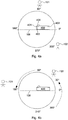
- FIG. 4a An example of the operation of method 300 is illustrated in figures 4a and 4b .
- FIG 4a the arrangement of sources 101, 102 is identical to that shown in figure 2a .
- a recording device 400 records sounds from a speaker 101 located at 90° and a speaker 102 located at 300° relative to an origin 106.
- the recording device 400 comprises three microphones 401-403 in a planar (or alternatively 3D) array.
- the recording device further comprises a camera 404.
- Figure 4b represents a 90° clockwise rotation of the user/device.
- Method 300 described above is used to process the recorded audio signal.
- Source 101 is rotated anti-clockwise to an apparent position of 180° to the origin 106, as was the case in figure 2c . Due to the determination of location of sound sources 101, 102, the correct initial position of source 102 is identified as being located at 300° rather than at 60°, unlike in figure 2b .
- Applying the 90° anticlockwise rotation results in source 102 being perceived to be at an angle of 30° to the origin 106.
- the perceived rotated positions of sources 101, 102 remain 150° apart, and the rotated sound will match a rotated video displayed to a user.
- Sound sources may be localised for example using a predefined calibration of the recording device.
- a calibration matrix H which maps the received signal to source locations may be estimated.
- the calibration matrix may be determined from sounds played at known source locations.
- the calibration may be performed for the recording device during its manufacture and stored in the device for later use.
- the estimation of the calibration matrix H may be similar to the estimation of a head-related transfer function [see reference 1].
- Other example algorithms to estimate the calibration matrix H include a multiplicative transfer function method [reference 2] or the relative transfer function estimation [reference 3]. Any appropriate input signal can be chosen for these methods. Some commonly used signals are white noise or speech.
- the sound source locations may be estimated from the signals received by the recording device.
- One algorithm that may be used to estimate the location of sound signals is known as the L 2 norm constraint least squares approach. This approach ensures the sparsity of the number of active sources.
- the relationship establishes the location of the sound sources by determining the values of s for which the function
- the recorded audio signal is divided into overlapping frames and transformed into the frequency domain, for example using a short-time Fourier transform (STFT) to produce the observed signal vector y .
- STFT short-time Fourier transform
- Other transforms may also be applicable, provided the appropriate reverse transform is applied after rotation to transform the signal back into the time domain.
- FIG. 5 illustrates an example of an algorithm 500 which can be used to rotate the audio signal.
- Algorithm 500 comprises generating a rotation matrix which relates the identified locations of sound sources to desired locations.
- Algorithm 500 may be used in particular where a calibration matrix H and sound source vector s have been determined during localisation, as described above.
- a rotation matrix is generated, which may comprise rotating the calibration matrix H to produce a rotated calibration matrix ⁇ whose columns are reordered from the columns of the original calibration matrix H according to the desired source locations
- the rotated signal ⁇ is transformed back into the time domain to produce a rotated audio signal.
- An alternative algorithm 600 is illustrated in figure 6 .
- sound sources in the signal are classified as front sound sources or back sound sources, i.e. whether they are in front or behind the audio recording device.
- Algorithm 600 thus does not require an exact location for each sound source to be determined in the localisation stage, only that the localisation is sufficient to determine whether a sound source is in front of the recording device or behind it. For example energy or other characteristics of the sound may be used to determine the appropriate classification. Classifications other than front/back may be used.
- the classification may classify sound sources as being in any first region or second region relative to the recording device, where the first and second regions are mutually exclusive.
- the algorithm 600 may classify sound sources as being above the recording device or below the recording device.
- the audio signal y is separated into two components, y front comprising signals from those sound sources classified as front sound sources and y back comprising signals from those sound sources classified as back sound sources.
- each of the separated signals y front and y back is rotated separately, for example using the sine/cosine rotation of equation ( 1 ).
- the two signals y front and y back are rotated by the same angle, but in opposite directions.
- the rotated signals are recombined to form a rotated output signal.
- the inverse transform may be applied, either before or after recombination, to transform the output signal into the time domain.
- BSS blind source separation
- a further alternative algorithm 700 is illustrated in figure 7 .
- sound sources in the signal are classified as front sound sources or back sound sources, similarly to step 601 above.
- a direction of arrival (DOA) of each sound source at the recording device is determined or estimated, for example using a two channel DOA algorithm.
- Step 702 may alternatively be performed before step 701.
- a full 2D plane direction of arrival an azimuth range of 0-360°
- the audio signal is rotated by applying a rotation matrix to rotate sound sources in consistent directions, similarly to steps 501 and 502 of algorithm 500, to produce a rotated output signal.
- the rotated output signal is inverse Fourier transformed into the time domain to produce a rotated audio signal.
- the methods and algorithms can be applied to any number of sound sources. Further, the methods and algorithms can be extended to enable audio rotation where the sound sources are distributed around full 3D space, not just in the 2D azimuthal plane.
- the localisation step may determine the 3D position of sound sources.
- the rotated matrix of algorithm 500 may relate sound source locations to desired sound source locations in full 3D space.
- the algorithm 600 may further comprise classifying the elevation of the sound sources, for example classifying sources as above the recording device or below the recording device. The audio signal may then be separated into those components classified as front and back and/or top and bottom. A similar elevation classification may be used in algorithm 700.
- a sensor may be used in addition to the microphones, or may replace one of the required microphones.
- the sensor may be any sensor that is able to determine a position of sound sources, or to classify their position (such as front/back, top/bottom).
- the sensor may be a vector microphone or a camera (using image processing to determine locations of sound sources).
- the methods and algorithms described above may be implemented with audio processing hardware, for example an audio processor associated with an audio, AR, or VR device.
- the processor may receive a non-rotated audio signal through an input, apply the above methods and algorithms to rotate the signal, and output a rotated audio signal through an output.
- the methods and algorithms may be implemented in software, such as audio processing software associated with an audio device or stand-alone software, such as a downloadable app.
- the methods and algorithms described above may be used with a smart device such as a smartphone, portable computer, or augmented reality device. For example, they can be used by the user of a smart device to rotate recorded audio signals.
- a smart device such as a smartphone, portable computer, or augmented reality device.
- the calling/called parties in the teleconference may have the flexibility to change the video and audio they see and hear, for example rotating the sound as the listener moves around a room.
- the methods and algorithms may be used to redistribute sound around a listener, for example to reposition sound sources from the side to the front of the listener. In this way, side sound sources which may otherwise be considered as interference signals to be discarded may be refocused by rotating them to the front of the listener. Further, the methods and algorithms may be used to remix music signals.
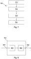
- FIG. 8 illustrates schematically an audio processing device 800 for performing a method according to the examples described above.
- the device 800 comprises an input 801 for receiving a multi-channel audio signal and an output 802 for outputting a rotated audio signal.
- the device 800 may be a processor suitably arranged or programmed to perform the methods as described above.
- the processor may for example comprise a location module 803, which is configured to determine the location of sound sources within an audio signal received at the input 801, and a rotation module 804 configured to apply a rotation operation to the audio signal, a direction of the rotation operation being dependent on the location of the sound sources in the signal.
- the device 800 may further comprise Fourier transform modules for transforming the input audio signal into the frequency domain and for transforming the output audio signal back into the time domain.
- the device 800 may also comprise further modules configured to perform other aspects of the methods described above.
Landscapes
- Physics & Mathematics (AREA)
- Engineering & Computer Science (AREA)
- Acoustics & Sound (AREA)
- Signal Processing (AREA)
- Stereophonic System (AREA)
- Circuit For Audible Band Transducer (AREA)
Priority Applications (2)
| Application Number | Priority Date | Filing Date | Title |
|---|---|---|---|
| EP16206555.1A EP3340648B1 (de) | 2016-12-23 | 2016-12-23 | Verarbeitung von audiosignalen |
| US15/828,881 US10602297B2 (en) | 2016-12-23 | 2017-12-01 | Processing audio signals |
Applications Claiming Priority (1)
| Application Number | Priority Date | Filing Date | Title |
|---|---|---|---|
| EP16206555.1A EP3340648B1 (de) | 2016-12-23 | 2016-12-23 | Verarbeitung von audiosignalen |
Publications (2)
| Publication Number | Publication Date |
|---|---|
| EP3340648A1 true EP3340648A1 (de) | 2018-06-27 |
| EP3340648B1 EP3340648B1 (de) | 2019-11-27 |
Family
ID=57799489
Family Applications (1)
| Application Number | Title | Priority Date | Filing Date |
|---|---|---|---|
| EP16206555.1A Active EP3340648B1 (de) | 2016-12-23 | 2016-12-23 | Verarbeitung von audiosignalen |
Country Status (2)
| Country | Link |
|---|---|
| US (1) | US10602297B2 (de) |
| EP (1) | EP3340648B1 (de) |
Families Citing this family (2)
| Publication number | Priority date | Publication date | Assignee | Title |
|---|---|---|---|---|
| KR102602942B1 (ko) * | 2019-01-07 | 2023-11-16 | 삼성전자 주식회사 | 오디오 정보 처리 장치의 위치에 기반하여 오디오 처리 알고리즘을 결정하는 전자 장치 및 방법 |
| US20220191305A1 (en) * | 2020-12-11 | 2022-06-16 | International Business Machines Corporation | Identifying a voice command boundary |
Citations (3)
| Publication number | Priority date | Publication date | Assignee | Title |
|---|---|---|---|---|
| US6021206A (en) * | 1996-10-02 | 2000-02-01 | Lake Dsp Pty Ltd | Methods and apparatus for processing spatialised audio |
| EP2346028A1 (de) * | 2009-12-17 | 2011-07-20 | Fraunhofer-Gesellschaft zur Förderung der Angewandten Forschung e.V. | Vorrichtung und Verfahren zur Umwandlung eines ersten parametrisch beabstandeten Audiosignals in ein zweites parametrisch beabstandetes Audiosignal |
| US20160142851A1 (en) * | 2013-06-18 | 2016-05-19 | Dolby Laboratories Licensing Corporation | Method for Generating a Surround Sound Field, Apparatus and Computer Program Product Thereof |
Family Cites Families (6)
| Publication number | Priority date | Publication date | Assignee | Title |
|---|---|---|---|---|
| JP4107300B2 (ja) * | 2005-03-10 | 2008-06-25 | ヤマハ株式会社 | サラウンドシステム |
| CN104935913B (zh) * | 2014-03-21 | 2018-12-04 | 杜比实验室特许公司 | 处理多个装置采集的音频或视频信号 |
| KR20160058607A (ko) | 2014-11-17 | 2016-05-25 | 현대자동차주식회사 | 영상 처리 장치 및 영상 처리 방법 |
| US9767618B2 (en) * | 2015-01-28 | 2017-09-19 | Samsung Electronics Co., Ltd. | Adaptive ambisonic binaural rendering |
| CN107950036B (zh) * | 2015-09-03 | 2020-06-05 | 杜比实验室特许公司 | 用于控制无线扬声器的音频棒 |
| US10251012B2 (en) * | 2016-06-07 | 2019-04-02 | Philip Raymond Schaefer | System and method for realistic rotation of stereo or binaural audio |
-
2016
- 2016-12-23 EP EP16206555.1A patent/EP3340648B1/de active Active
-
2017
- 2017-12-01 US US15/828,881 patent/US10602297B2/en active Active
Patent Citations (3)
| Publication number | Priority date | Publication date | Assignee | Title |
|---|---|---|---|---|
| US6021206A (en) * | 1996-10-02 | 2000-02-01 | Lake Dsp Pty Ltd | Methods and apparatus for processing spatialised audio |
| EP2346028A1 (de) * | 2009-12-17 | 2011-07-20 | Fraunhofer-Gesellschaft zur Förderung der Angewandten Forschung e.V. | Vorrichtung und Verfahren zur Umwandlung eines ersten parametrisch beabstandeten Audiosignals in ein zweites parametrisch beabstandetes Audiosignal |
| US20160142851A1 (en) * | 2013-06-18 | 2016-05-19 | Dolby Laboratories Licensing Corporation | Method for Generating a Surround Sound Field, Apparatus and Computer Program Product Thereof |
Non-Patent Citations (3)
| Title |
|---|
| C.I. CHENG; G.H. WAKEFIELD: "Introduction to head-related transfer functions (HRTFs): Representations of HRTFs in time, frequency, and space", AES: JOURNAL OF THE AUDIO ENGINEERING SOCIETY, vol. 49, no. 4, April 2001 (2001-04-01), pages 231 - 249 |
| ISRAEL COHEN: "Relative Transfer Function Identification Using Speech Signals", IEEE TRANSACTIONS ON SPEECH AND AUDIO PROCESSING, vol. 12, no. 5, October 2004 (2004-10-01), pages 451 - 459 |
| YEKUTIEL AVARGEL; ISRAEL COHEN: "On Multiplicative Transfer Function Approximation in the Short-Time Fourier Transform Domain", IEEE SIGNAL PROCESSING LETTERS, vol. 14, no. 5, June 2007 (2007-06-01), pages 337 - 340 |
Also Published As
| Publication number | Publication date |
|---|---|
| EP3340648B1 (de) | 2019-11-27 |
| US20180184225A1 (en) | 2018-06-28 |
| US10602297B2 (en) | 2020-03-24 |
Similar Documents
| Publication | Publication Date | Title |
|---|---|---|
| JP6466969B2 (ja) | 適応性のある関数に基づく矛盾しない音響場面再生のためのシステムおよび装置および方法 | |
| JP6367258B2 (ja) | オーディオ処理装置 | |
| US8160270B2 (en) | Method and apparatus for acquiring multi-channel sound by using microphone array | |
| CN102907120B (zh) | 用于声音处理的系统和方法 | |
| US10015443B2 (en) | Adjusting spatial congruency in a video conferencing system | |
| Amengual Garí et al. | Optimizations of the spatial decomposition method for binaural reproduction | |
| WO2017064368A1 (en) | Distributed audio capture and mixing | |
| JP2015019371A5 (de) | ||
| CN102859584A (zh) | 用以将第一参数式空间音频信号转换成第二参数式空间音频信号的装置与方法 | |
| Khan et al. | Video-aided model-based source separation in real reverberant rooms | |
| US20230096873A1 (en) | Apparatus, methods and computer programs for enabling reproduction of spatial audio signals | |
| CN114450977A (zh) | 用于在空间变换域中处理声场表示的装置、方法或计算机程序 | |
| US10602297B2 (en) | Processing audio signals | |
| CN108781310B (zh) | 选择要增强的视频的音频流的方法、装置、设备、介质 | |
| McKenzie et al. | Perceptually informed interpolation and rendering of spatial room impulse responses for room transitions | |
| Thiergart et al. | An acoustical zoom based on informed spatial filtering | |
| Laitinen et al. | Using spaced microphones with directional audio coding | |
| Gallo et al. | Extracting and re-rendering structured auditory scenes from field recordings | |
| Nguyen et al. | Spatialized audio multiparty teleconferencing with commodity miniature microphone array | |
| Vincent et al. | Acoustics: Spatial Properties | |
| He et al. | Time-Shifting-Based Primary Ambient Extraction | |
| Georgiou | Robust signal processing techniques for source localization and multisource spatial sound rendering for immersive environments | |
| Cobos Serrano | Application of sound source separation methods to advanced spatial audio systems |
Legal Events
| Date | Code | Title | Description |
|---|---|---|---|
| PUAI | Public reference made under article 153(3) epc to a published international application that has entered the european phase |
Free format text: ORIGINAL CODE: 0009012 |
|
| STAA | Information on the status of an ep patent application or granted ep patent |
Free format text: STATUS: THE APPLICATION HAS BEEN PUBLISHED |
|
| AK | Designated contracting states |
Kind code of ref document: A1 Designated state(s): AL AT BE BG CH CY CZ DE DK EE ES FI FR GB GR HR HU IE IS IT LI LT LU LV MC MK MT NL NO PL PT RO RS SE SI SK SM TR |
|
| AX | Request for extension of the european patent |
Extension state: BA ME |
|
| STAA | Information on the status of an ep patent application or granted ep patent |
Free format text: STATUS: REQUEST FOR EXAMINATION WAS MADE |
|
| STAA | Information on the status of an ep patent application or granted ep patent |
Free format text: STATUS: EXAMINATION IS IN PROGRESS |
|
| 17P | Request for examination filed |
Effective date: 20190102 |
|
| RBV | Designated contracting states (corrected) |
Designated state(s): AL AT BE BG CH CY CZ DE DK EE ES FI FR GB GR HR HU IE IS IT LI LT LU LV MC MK MT NL NO PL PT RO RS SE SI SK SM TR |
|
| 17Q | First examination report despatched |
Effective date: 20190215 |
|
| GRAP | Despatch of communication of intention to grant a patent |
Free format text: ORIGINAL CODE: EPIDOSNIGR1 |
|
| STAA | Information on the status of an ep patent application or granted ep patent |
Free format text: STATUS: GRANT OF PATENT IS INTENDED |
|
| INTG | Intention to grant announced |
Effective date: 20190717 |
|
| GRAS | Grant fee paid |
Free format text: ORIGINAL CODE: EPIDOSNIGR3 |
|
| GRAA | (expected) grant |
Free format text: ORIGINAL CODE: 0009210 |
|
| STAA | Information on the status of an ep patent application or granted ep patent |
Free format text: STATUS: THE PATENT HAS BEEN GRANTED |
|
| AK | Designated contracting states |
Kind code of ref document: B1 Designated state(s): AL AT BE BG CH CY CZ DE DK EE ES FI FR GB GR HR HU IE IS IT LI LT LU LV MC MK MT NL NO PL PT RO RS SE SI SK SM TR |
|
| REG | Reference to a national code |
Ref country code: GB Ref legal event code: FG4D |
|
| REG | Reference to a national code |
Ref country code: CH Ref legal event code: EP |
|
| REG | Reference to a national code |
Ref country code: AT Ref legal event code: REF Ref document number: 1208076 Country of ref document: AT Kind code of ref document: T Effective date: 20191215 |
|
| REG | Reference to a national code |
Ref country code: DE Ref legal event code: R096 Ref document number: 602016025010 Country of ref document: DE |
|
| REG | Reference to a national code |
Ref country code: IE Ref legal event code: FG4D |
|
| REG | Reference to a national code |
Ref country code: NL Ref legal event code: MP Effective date: 20191127 |
|
| REG | Reference to a national code |
Ref country code: LT Ref legal event code: MG4D |
|
| PG25 | Lapsed in a contracting state [announced via postgrant information from national office to epo] |
Ref country code: BG Free format text: LAPSE BECAUSE OF FAILURE TO SUBMIT A TRANSLATION OF THE DESCRIPTION OR TO PAY THE FEE WITHIN THE PRESCRIBED TIME-LIMIT Effective date: 20200227 Ref country code: FI Free format text: LAPSE BECAUSE OF FAILURE TO SUBMIT A TRANSLATION OF THE DESCRIPTION OR TO PAY THE FEE WITHIN THE PRESCRIBED TIME-LIMIT Effective date: 20191127 Ref country code: NO Free format text: LAPSE BECAUSE OF FAILURE TO SUBMIT A TRANSLATION OF THE DESCRIPTION OR TO PAY THE FEE WITHIN THE PRESCRIBED TIME-LIMIT Effective date: 20200227 Ref country code: GR Free format text: LAPSE BECAUSE OF FAILURE TO SUBMIT A TRANSLATION OF THE DESCRIPTION OR TO PAY THE FEE WITHIN THE PRESCRIBED TIME-LIMIT Effective date: 20200228 Ref country code: LT Free format text: LAPSE BECAUSE OF FAILURE TO SUBMIT A TRANSLATION OF THE DESCRIPTION OR TO PAY THE FEE WITHIN THE PRESCRIBED TIME-LIMIT Effective date: 20191127 Ref country code: NL Free format text: LAPSE BECAUSE OF FAILURE TO SUBMIT A TRANSLATION OF THE DESCRIPTION OR TO PAY THE FEE WITHIN THE PRESCRIBED TIME-LIMIT Effective date: 20191127 Ref country code: SE Free format text: LAPSE BECAUSE OF FAILURE TO SUBMIT A TRANSLATION OF THE DESCRIPTION OR TO PAY THE FEE WITHIN THE PRESCRIBED TIME-LIMIT Effective date: 20191127 Ref country code: LV Free format text: LAPSE BECAUSE OF FAILURE TO SUBMIT A TRANSLATION OF THE DESCRIPTION OR TO PAY THE FEE WITHIN THE PRESCRIBED TIME-LIMIT Effective date: 20191127 |
|
| PG25 | Lapsed in a contracting state [announced via postgrant information from national office to epo] |
Ref country code: IS Free format text: LAPSE BECAUSE OF FAILURE TO SUBMIT A TRANSLATION OF THE DESCRIPTION OR TO PAY THE FEE WITHIN THE PRESCRIBED TIME-LIMIT Effective date: 20200327 Ref country code: RS Free format text: LAPSE BECAUSE OF FAILURE TO SUBMIT A TRANSLATION OF THE DESCRIPTION OR TO PAY THE FEE WITHIN THE PRESCRIBED TIME-LIMIT Effective date: 20191127 Ref country code: HR Free format text: LAPSE BECAUSE OF FAILURE TO SUBMIT A TRANSLATION OF THE DESCRIPTION OR TO PAY THE FEE WITHIN THE PRESCRIBED TIME-LIMIT Effective date: 20191127 |
|
| PG25 | Lapsed in a contracting state [announced via postgrant information from national office to epo] |
Ref country code: AL Free format text: LAPSE BECAUSE OF FAILURE TO SUBMIT A TRANSLATION OF THE DESCRIPTION OR TO PAY THE FEE WITHIN THE PRESCRIBED TIME-LIMIT Effective date: 20191127 |
|
| PG25 | Lapsed in a contracting state [announced via postgrant information from national office to epo] |
Ref country code: DK Free format text: LAPSE BECAUSE OF FAILURE TO SUBMIT A TRANSLATION OF THE DESCRIPTION OR TO PAY THE FEE WITHIN THE PRESCRIBED TIME-LIMIT Effective date: 20191127 Ref country code: ES Free format text: LAPSE BECAUSE OF FAILURE TO SUBMIT A TRANSLATION OF THE DESCRIPTION OR TO PAY THE FEE WITHIN THE PRESCRIBED TIME-LIMIT Effective date: 20191127 Ref country code: RO Free format text: LAPSE BECAUSE OF FAILURE TO SUBMIT A TRANSLATION OF THE DESCRIPTION OR TO PAY THE FEE WITHIN THE PRESCRIBED TIME-LIMIT Effective date: 20191127 Ref country code: CZ Free format text: LAPSE BECAUSE OF FAILURE TO SUBMIT A TRANSLATION OF THE DESCRIPTION OR TO PAY THE FEE WITHIN THE PRESCRIBED TIME-LIMIT Effective date: 20191127 Ref country code: EE Free format text: LAPSE BECAUSE OF FAILURE TO SUBMIT A TRANSLATION OF THE DESCRIPTION OR TO PAY THE FEE WITHIN THE PRESCRIBED TIME-LIMIT Effective date: 20191127 Ref country code: PT Free format text: LAPSE BECAUSE OF FAILURE TO SUBMIT A TRANSLATION OF THE DESCRIPTION OR TO PAY THE FEE WITHIN THE PRESCRIBED TIME-LIMIT Effective date: 20200419 |
|
| REG | Reference to a national code |
Ref country code: CH Ref legal event code: PL |
|
| REG | Reference to a national code |
Ref country code: DE Ref legal event code: R081 Ref document number: 602016025010 Country of ref document: DE Owner name: GOODIX TECHNOLOGY (HK) COMPANY LIMITED, CN Free format text: FORMER OWNER: NXP B.V., EINDHOVEN, NL |
|
| REG | Reference to a national code |
Ref country code: BE Ref legal event code: MM Effective date: 20191231 |
|
| REG | Reference to a national code |
Ref country code: DE Ref legal event code: R097 Ref document number: 602016025010 Country of ref document: DE |
|
| PG25 | Lapsed in a contracting state [announced via postgrant information from national office to epo] |
Ref country code: MC Free format text: LAPSE BECAUSE OF FAILURE TO SUBMIT A TRANSLATION OF THE DESCRIPTION OR TO PAY THE FEE WITHIN THE PRESCRIBED TIME-LIMIT Effective date: 20191127 Ref country code: SK Free format text: LAPSE BECAUSE OF FAILURE TO SUBMIT A TRANSLATION OF THE DESCRIPTION OR TO PAY THE FEE WITHIN THE PRESCRIBED TIME-LIMIT Effective date: 20191127 Ref country code: SM Free format text: LAPSE BECAUSE OF FAILURE TO SUBMIT A TRANSLATION OF THE DESCRIPTION OR TO PAY THE FEE WITHIN THE PRESCRIBED TIME-LIMIT Effective date: 20191127 |
|
| REG | Reference to a national code |
Ref country code: AT Ref legal event code: MK05 Ref document number: 1208076 Country of ref document: AT Kind code of ref document: T Effective date: 20191127 |
|
| PLBE | No opposition filed within time limit |
Free format text: ORIGINAL CODE: 0009261 |
|
| STAA | Information on the status of an ep patent application or granted ep patent |
Free format text: STATUS: NO OPPOSITION FILED WITHIN TIME LIMIT |
|
| PG25 | Lapsed in a contracting state [announced via postgrant information from national office to epo] |
Ref country code: IE Free format text: LAPSE BECAUSE OF NON-PAYMENT OF DUE FEES Effective date: 20191223 Ref country code: FR Free format text: LAPSE BECAUSE OF NON-PAYMENT OF DUE FEES Effective date: 20200127 Ref country code: LU Free format text: LAPSE BECAUSE OF NON-PAYMENT OF DUE FEES Effective date: 20191223 |
|
| 26N | No opposition filed |
Effective date: 20200828 |
|
| PG25 | Lapsed in a contracting state [announced via postgrant information from national office to epo] |
Ref country code: PL Free format text: LAPSE BECAUSE OF FAILURE TO SUBMIT A TRANSLATION OF THE DESCRIPTION OR TO PAY THE FEE WITHIN THE PRESCRIBED TIME-LIMIT Effective date: 20191127 Ref country code: BE Free format text: LAPSE BECAUSE OF NON-PAYMENT OF DUE FEES Effective date: 20191231 Ref country code: AT Free format text: LAPSE BECAUSE OF FAILURE TO SUBMIT A TRANSLATION OF THE DESCRIPTION OR TO PAY THE FEE WITHIN THE PRESCRIBED TIME-LIMIT Effective date: 20191127 Ref country code: SI Free format text: LAPSE BECAUSE OF FAILURE TO SUBMIT A TRANSLATION OF THE DESCRIPTION OR TO PAY THE FEE WITHIN THE PRESCRIBED TIME-LIMIT Effective date: 20191127 Ref country code: LI Free format text: LAPSE BECAUSE OF NON-PAYMENT OF DUE FEES Effective date: 20191231 Ref country code: CH Free format text: LAPSE BECAUSE OF NON-PAYMENT OF DUE FEES Effective date: 20191231 |
|
| PG25 | Lapsed in a contracting state [announced via postgrant information from national office to epo] |
Ref country code: IT Free format text: LAPSE BECAUSE OF FAILURE TO SUBMIT A TRANSLATION OF THE DESCRIPTION OR TO PAY THE FEE WITHIN THE PRESCRIBED TIME-LIMIT Effective date: 20191127 |
|
| PG25 | Lapsed in a contracting state [announced via postgrant information from national office to epo] |
Ref country code: CY Free format text: LAPSE BECAUSE OF FAILURE TO SUBMIT A TRANSLATION OF THE DESCRIPTION OR TO PAY THE FEE WITHIN THE PRESCRIBED TIME-LIMIT Effective date: 20191127 |
|
| PG25 | Lapsed in a contracting state [announced via postgrant information from national office to epo] |
Ref country code: HU Free format text: LAPSE BECAUSE OF FAILURE TO SUBMIT A TRANSLATION OF THE DESCRIPTION OR TO PAY THE FEE WITHIN THE PRESCRIBED TIME-LIMIT; INVALID AB INITIO Effective date: 20161223 Ref country code: MT Free format text: LAPSE BECAUSE OF FAILURE TO SUBMIT A TRANSLATION OF THE DESCRIPTION OR TO PAY THE FEE WITHIN THE PRESCRIBED TIME-LIMIT Effective date: 20191127 |
|
| GBPC | Gb: european patent ceased through non-payment of renewal fee |
Effective date: 20201223 |
|
| PG25 | Lapsed in a contracting state [announced via postgrant information from national office to epo] |
Ref country code: GB Free format text: LAPSE BECAUSE OF NON-PAYMENT OF DUE FEES Effective date: 20201223 |
|
| PG25 | Lapsed in a contracting state [announced via postgrant information from national office to epo] |
Ref country code: TR Free format text: LAPSE BECAUSE OF FAILURE TO SUBMIT A TRANSLATION OF THE DESCRIPTION OR TO PAY THE FEE WITHIN THE PRESCRIBED TIME-LIMIT Effective date: 20191127 |
|
| PG25 | Lapsed in a contracting state [announced via postgrant information from national office to epo] |
Ref country code: MK Free format text: LAPSE BECAUSE OF FAILURE TO SUBMIT A TRANSLATION OF THE DESCRIPTION OR TO PAY THE FEE WITHIN THE PRESCRIBED TIME-LIMIT Effective date: 20191127 |
|
| PGFP | Annual fee paid to national office [announced via postgrant information from national office to epo] |
Ref country code: DE Payment date: 20231214 Year of fee payment: 8 |