EP2344873B1 - Collection system for purification flowstreams - Google Patents
Collection system for purification flowstreams Download PDFInfo
- Publication number
- EP2344873B1 EP2344873B1 EP09756585.7A EP09756585A EP2344873B1 EP 2344873 B1 EP2344873 B1 EP 2344873B1 EP 09756585 A EP09756585 A EP 09756585A EP 2344873 B1 EP2344873 B1 EP 2344873B1
- Authority
- EP
- European Patent Office
- Prior art keywords
- separator
- collection system
- pressure
- gas
- dripper
- Prior art date
- Legal status (The legal status is an assumption and is not a legal conclusion. Google has not performed a legal analysis and makes no representation as to the accuracy of the status listed.)
- Active
Links
- 238000000746 purification Methods 0.000 title description 2
- 239000007788 liquid Substances 0.000 claims description 49
- 239000002904 solvent Substances 0.000 claims description 16
- 238000000034 method Methods 0.000 claims description 10
- 238000004587 chromatography analysis Methods 0.000 claims description 7
- 230000008569 process Effects 0.000 claims description 7
- 238000004808 supercritical fluid chromatography Methods 0.000 claims description 7
- 238000004128 high performance liquid chromatography Methods 0.000 claims description 4
- 239000007789 gas Substances 0.000 description 24
- 239000007791 liquid phase Substances 0.000 description 9
- 238000012387 aerosolization Methods 0.000 description 5
- 239000006184 cosolvent Substances 0.000 description 4
- 239000007792 gaseous phase Substances 0.000 description 4
- 239000012071 phase Substances 0.000 description 4
- 238000000926 separation method Methods 0.000 description 4
- 239000000443 aerosol Substances 0.000 description 3
- 238000012864 cross contamination Methods 0.000 description 3
- 238000010586 diagram Methods 0.000 description 3
- 239000012530 fluid Substances 0.000 description 3
- 239000000203 mixture Substances 0.000 description 3
- 238000011084 recovery Methods 0.000 description 3
- 150000001875 compounds Chemical class 0.000 description 2
- 238000010438 heat treatment Methods 0.000 description 2
- 238000010008 shearing Methods 0.000 description 2
- 230000015572 biosynthetic process Effects 0.000 description 1
- 238000004581 coalescence Methods 0.000 description 1
- 230000003750 conditioning effect Effects 0.000 description 1
- 238000000605 extraction Methods 0.000 description 1
- 230000008014 freezing Effects 0.000 description 1
- 238000007710 freezing Methods 0.000 description 1
- 230000005484 gravity Effects 0.000 description 1
- 230000014759 maintenance of location Effects 0.000 description 1
- 238000012986 modification Methods 0.000 description 1
- 230000004048 modification Effects 0.000 description 1
- 230000009467 reduction Effects 0.000 description 1
- 238000004366 reverse phase liquid chromatography Methods 0.000 description 1
- 230000007480 spreading Effects 0.000 description 1
- 238000003892 spreading Methods 0.000 description 1
- 238000003860 storage Methods 0.000 description 1
- 238000000194 supercritical-fluid extraction Methods 0.000 description 1
Images
Classifications
-
- B—PERFORMING OPERATIONS; TRANSPORTING
- B01—PHYSICAL OR CHEMICAL PROCESSES OR APPARATUS IN GENERAL
- B01D—SEPARATION
- B01D15/00—Separating processes involving the treatment of liquids with solid sorbents; Apparatus therefor
- B01D15/08—Selective adsorption, e.g. chromatography
- B01D15/10—Selective adsorption, e.g. chromatography characterised by constructional or operational features
-
- G—PHYSICS
- G01—MEASURING; TESTING
- G01N—INVESTIGATING OR ANALYSING MATERIALS BY DETERMINING THEIR CHEMICAL OR PHYSICAL PROPERTIES
- G01N30/00—Investigating or analysing materials by separation into components using adsorption, absorption or similar phenomena or using ion-exchange, e.g. chromatography or field flow fractionation
- G01N30/02—Column chromatography
- G01N30/80—Fraction collectors
- G01N30/82—Automatic means therefor
-
- G—PHYSICS
- G01—MEASURING; TESTING
- G01N—INVESTIGATING OR ANALYSING MATERIALS BY DETERMINING THEIR CHEMICAL OR PHYSICAL PROPERTIES
- G01N30/00—Investigating or analysing materials by separation into components using adsorption, absorption or similar phenomena or using ion-exchange, e.g. chromatography or field flow fractionation
- G01N30/02—Column chromatography
- G01N30/26—Conditioning of the fluid carrier; Flow patterns
- G01N30/28—Control of physical parameters of the fluid carrier
- G01N30/32—Control of physical parameters of the fluid carrier of pressure or speed
- G01N2030/324—Control of physical parameters of the fluid carrier of pressure or speed speed, flow rate
-
- G—PHYSICS
- G01—MEASURING; TESTING
- G01N—INVESTIGATING OR ANALYSING MATERIALS BY DETERMINING THEIR CHEMICAL OR PHYSICAL PROPERTIES
- G01N30/00—Investigating or analysing materials by separation into components using adsorption, absorption or similar phenomena or using ion-exchange, e.g. chromatography or field flow fractionation
- G01N30/02—Column chromatography
Definitions
- a continuous collection system for recovery of dissolved solutes from the output stream of a purification system has been developed.
- the system may be either based on or used with supercritical fluid chromatography (SFC) or extraction (SFE) or other high pressure systems.
- SFC supercritical fluid chromatography
- SFE extraction
- HPLC high performance liquid chromatography
- a liquid co-solvent is mixed with a supercritical gas, such as CO2, to vary its strength as a solvent.
- a supercritical gas such as CO2
- the use of a high pressure system leads to undesired aerosolization of the co-solvent during collection of fractions of the eluting mixed gas liquid solvent stream. This aerosolization causes cross-contamination when attempting to collect separated compounds using a single fraction collection device for depressurization from a continuous stream.
- Prior art collection systems for supercritical fluid chromatography managed this problem by providing collection systems in which the collection vessels are maintained under high pressure. See, for example, US6632353 , US6685828 , US6413428 and US6656354 .
- the invention provides a collection system for continuous collections of fractions from a flowstream exiting a supercritical fluid chromatography system (5), the collection system comprising:
- the invention provides a collection system for collecting samples from a flowstream exiting a high performance liquid chromatography system, the collection system comprising:
- the invention provides a process for collecting samples in a flow stream exiting a supercritical fluid chromatography system (5), the flowstream having gas and liquid components, the process comprising the steps of:
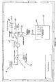
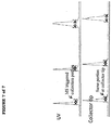
- an output flow stream 5 from a chromatography system flows through an automated back pressure regulator 10 toward a fraction collector 15, the fraction collector 15 maintained at a reduced pressure setting (reduced relative to the pressure used in the chromatography or extraction system), preferably at atmospheric pressure.
- the fraction collector is an open bed collector, although collectors that require a pressure above atmospheric pressure, for example up to below system pressure, about 100 bar.
- the term "below system pressure” refers to a pressure of up to 100 bar above atmospheric pressure.
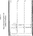
- the flow stream comprises a high pressure, monophasic fluid of 1) one or more incompressible liquids, in solution with 2) one or more highly dissolved gasses, liquefied gasses or supercritical fluids, and 3) dissolved solutes of interest.
- Incoming flow is reduced from system operating pressure, which is typically 100 bar or greater, to below system pressure down to atmospheric pressure.
- a first drop in pressure occurs as the flow stream exits the first backpressure regulator 10, to a level that is less than 100 bar and at or above atmospheric pressure (1 bar or 14 psi).
- the lower limit on pressure is atmospheric pressure or 5, 10, 15, 20, 25, 30, 35, 40, 45, 50, 55, 60, 65, 70, 75, 80, 85, 90, or 95 bar; the upper limit on pressure is less than 100 bar, 95, 90, 85, 80, 75, 70, 65, 60, 55, 50, 45, 40, 35, 30, 25, 20, 15, 10 or 5 bar.
- a solvent make-up pump 20 can be used to add solvent as necessary to the flow stream as it exits the back pressure regulator 10.
- Software is used to monitor the level of solvent in the flow stream and to maintain a minimal level of solvent flow, to allow near complete sample recovery. Maintaining the solvent flow within certain levels, for example, at least 10% of the total flow, usually between about 10% to 50% of the total flow, up to maximum system solvent flow, provides a predictable delay in peak flow through the system, and helps prevent peaks from spreading out and overlapping each other.
- the makeup solvent can be similar to or the same as the co-solvent used in the separation, or similar to the polarity of the compound that is being collected. This conditioning process also further minimizes the presence of aerosols within the flowstream.
- the determination of makeup solvent level is within the ability of one skilled in the art of chromatography systems, and is based on the solubility of the solute of interest, flow rate, hardware considerations, and other factors.
- the gas cools with the drop in pressure, and the flow stream usually requires heating (when supercritical fluids are used) to prevent formation of ice.
- the flow stream is heated via the heat exchanger 25, which monitors the temperature of the flow stream and heats the flow in a controlled manner, to achieve a flow stream comprised of a gaseous phase and a liquid phase.
- the flow stream will be maintained at a temperature of about 25° C to about 100°C, and the temperature will vary depending on the application. For example, if the solute is not thermally stable, a lower temperature may be needed, whereas a solute having a higher freezing point may require a higher temperature.
- the gaseous phase is comprised in the majority of the original dissolved or liquefied gaseous or supercritical components as well as a minor portion of evaporated liquid.
- the liquid phase is comprised primarily of the original liquid components (co-solvent) of the high pressure monophasic stream and dissolved solutes, as well as a minor amount of dissolved gasses from the gaseous phase.
- the flowstream is introduced into a single cylindrical vapor liquid separator 30 from which the majority of the gaseous and liquid phases exit by separate paths 32, 34.
- a single cylindrical vapor liquid separator 30 from which the majority of the gaseous and liquid phases exit by separate paths 32, 34.
- more than one separator, placed in series or in parallel, can be used.
- the collection system of the invention needs only a single gas-liquid separator.
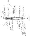
- the gas-liquid separator is shown in more detail in Figure 2 .
- the separator comprises an inlet flow port 50, a gas vent 55, a top cap 60, an outer vessel 70, an inner tube 75, a bottom cap 80, a liquid outflow port 85, and a drain port 90.
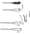
- a specially tapered tube with an increasing internal diameter, called the dripper 65, is inserted into the separator.
- the mouth of the dripper 67(through which the flow exits the dripper into the separator, the outlet) is wider than the diameter of the dripper where the flow enters the dripper 66 (inlet).
- the dimensions of the dripper are optimized for the system's flow rates, which assist in consolidating aerosol into a unified liquid stream.
- the ratio of the diameter of the outlet to the diameter of the inlet is between 2 - 100 to 1.
- the ratio of the diameter of the outlet to the diameter of the inlet is between about 2 - 4 to one, preferably about three to one.
- the ratio can be adjusted to accomodate flow rates of up to 1000 g/min.
- the flow stream mixture is directed to impact an inner wall 78 of the dripper at an angle tangential to the impact wall 76 of the separator, is preferably less than 45 degrees. This is the angle of the dripper's outlet in reference to a tangential plane at the impact point on the impact wall. This angle is not necessarily in a vertical orientation, and is the tangential angle.
- the angle of the dripper, relative to the separator's downward pointing vertical axis is between 10 and 80 degrees. In other words, the exit of the dripper is neither straight down nor straight sideways, but rather in-between. This angle is in a vertical orientation, and is not the tangential angle and preferably less than 45 degrees.
- Coalescence starts inside the dripper, and continues at the impact point for the liquid droplets of the stream.
- the dripper reaches down into the separator more than half way, minimizing the length of liquid flow path in the separator.
- the impact point and angle of impact serve to direct the liquid stream into a downward spiral toward the liquid exit point 85.
- the liquid then drains toward the bottom of the separator into the fraction collector 15 and collection vessels 47, such as test tubes, while the gaseous component rises to the gas vent exit 55 near the top of the separator.
- a second backpressure regulator 45 controls the internal pressure of the separator, controlling the pressure of the gas as it leaves the separator, and providing a force for driving the solvent to the fraction collector.
- the volume of the dripper 65 is substantially less than the volume of the inner tube 65 of the separator, approximately 50 - 100 times less for a flow rate of 100 g/min.
- the sizes of both the separator and dripper are optimized for the system's flow rate, resulting in a smaller dead volume and lower cross contamination.
- the internal cavity of the separator is maintained at an elevated pressure, for example, between about 1 bar to 100 bar, by means of the fixed or tunable flow restrictor (the second backpressure regulator 45 through which the gaseous flowstream passes.
- the internal pressurization provides two important functions. First, it reduces the kinetic energy of the gaseous components entering the separator. This provides less shearing force between vapor and liquid components of the entering stream.
- the benefits of lower shearing forces on the liquid phase include: 1) lower impact velocity of liquid droplets on the separator wall which results in dramatically lower re-aerosolization of the liquid phase; and 2) lower overall volume requirement for the separator which reduces the steady-state volume of liquid held in the chamber at any given composition of gas and liquid entering the separator.
- Internal pressurization further provides a driving force to remove the liquid through a second restrictive path originating near the bottom of the container.
- the restriction of the liquid flow path is selected to allow drainage slightly faster than the highest desired flow rate of liquid into the separator, as determined by the system flow rate. The restriction insures that the majority of entering gas phase components exit through the gas vent flowstream.
- the embodiment depicted in Figures 2 and 3 is designed for flow rates of up to about 100 g/min.
- the system can be scaled up or down, depending on the needs of the user.
- the system can be modified for use with flow rates anywhere between 10 and 1,000 g/min.
- the goal in designing a system that will work with a particular flow rate is to provide the appropriate reduction in velocity of the flow stream as it enters the separator, to minimize aerosolization of the liquid portion of the flow stream. Experimentation to optimize elements in a collection system is routinely conducted by those skilled in the art.
- the use of the dripper also eliminates the need for any baffle element near the gas vent since there is little liquid carried upwards along the separator wall.
- the liquid flowstream exiting the separator can be diverted by a valve to a variety of collection reservoirs.
- Such collection reservoirs may be intended for either recovery of desirable solutes in the liquid phase, or as a storage point for undesired solutes and solvents from the flow stream.
- the collection system can be easily automated in several ways. Selection of a multiport valve or a series of valves can direct multiple discrete flow segments to separate collection vessels. Also, since the flowstream is primarily liquid with a minor amount of entrained gas, it can be adapted to commercially available fraction collection systems, such as those used in HPLC systems, with only minor modifications.
- a rinse solvent can be pumped into the separation chamber through a rinse pump to clean the separator in between sample collection or sample runs.
- automation of the separator pressure control can be used to minimize excess gas exiting through the liquid path, by dynamically optimizing pressure for the current flow rate and gas/liquid ratio.
- the separator can be heated to a level, determined by the heat exchange capacity of the flows, by means of an infrared or resistive heating element to further drive out dissolved gasses and further minimize residual aerosols.
- automated rinsing of the chamber walls can be implemented, to minimize carryover between individual samples.
- the system can also be extended to multiple separators for parallel or serial collections, depending on the needs of the user.
- an initial separator could be optimized to separate the majority of the gas phase, diverting the liquid phase and the remaining portion of the gas phase to a second separator.
- the second separator would be optimized for lower gas flows, and would complete the separation of the gas and liquid phases.
Landscapes
- Chemical & Material Sciences (AREA)
- Analytical Chemistry (AREA)
- Chemical Kinetics & Catalysis (AREA)
- Physics & Mathematics (AREA)
- Health & Medical Sciences (AREA)
- Life Sciences & Earth Sciences (AREA)
- Biochemistry (AREA)
- General Health & Medical Sciences (AREA)
- General Physics & Mathematics (AREA)
- Immunology (AREA)
- Pathology (AREA)
- Sampling And Sample Adjustment (AREA)
- Treatment Of Liquids With Adsorbents In General (AREA)
Applications Claiming Priority (2)
| Application Number | Priority Date | Filing Date | Title |
|---|---|---|---|
| US19902608P | 2008-11-12 | 2008-11-12 | |
| PCT/US2009/006059 WO2010056313A1 (en) | 2008-11-12 | 2009-11-12 | Collection system for purification flowstreams |
Publications (2)
| Publication Number | Publication Date |
|---|---|
| EP2344873A1 EP2344873A1 (en) | 2011-07-20 |
| EP2344873B1 true EP2344873B1 (en) | 2018-05-30 |
Family
ID=41591639
Family Applications (1)
| Application Number | Title | Priority Date | Filing Date |
|---|---|---|---|
| EP09756585.7A Active EP2344873B1 (en) | 2008-11-12 | 2009-11-12 | Collection system for purification flowstreams |
Country Status (5)
| Country | Link |
|---|---|
| US (2) | US9205350B2 (enExample) |
| EP (1) | EP2344873B1 (enExample) |
| JP (1) | JP5597203B2 (enExample) |
| CN (1) | CN102216769B (enExample) |
| WO (1) | WO2010056313A1 (enExample) |
Families Citing this family (10)
| Publication number | Priority date | Publication date | Assignee | Title |
|---|---|---|---|---|
| CN103619433B (zh) * | 2011-06-17 | 2016-10-19 | 沃特世科技公司 | 用于超临界流体色谱的开床式常压收集的方法与装置 |
| EP3250325A4 (en) | 2015-01-30 | 2018-09-12 | Agilent Technologies, Inc. | Impact centrifugal separator and associated methods for fraction collection in supercritical fluid systems |
| CN107615063B (zh) * | 2015-04-10 | 2021-04-20 | 沃特世科技公司 | 气液分离后二氧化碳基色谱系统的冷却液体洗脱液 |
| WO2017143158A1 (en) * | 2016-02-18 | 2017-08-24 | Waters Technologies Corporation | Method of using chemical tags to improve the identification, quantification and spatial localization of components in a sample |
| CN109564200B (zh) * | 2016-08-15 | 2022-07-08 | 安捷伦科技有限公司 | 用于收集色谱级分的气液分离器 |
| US11015142B1 (en) * | 2016-10-20 | 2021-05-25 | Unified Science, LLC | Extraction system and methods for preparing a botanical oil |
| US10717024B2 (en) * | 2016-10-25 | 2020-07-21 | Waters Technologies Corporation | Gas liquid separator and associated systems and methods |
| DE102017130820A1 (de) * | 2017-05-16 | 2018-11-22 | Alexander Bozic | Gas-Flüssig-Abscheider für eine Chromatographie-Anlage |
| CN109357976A (zh) * | 2018-10-25 | 2019-02-19 | 中国海洋石油集团有限公司 | 一种多相流自动采集计量系统 |
| JP7063249B2 (ja) * | 2018-11-22 | 2022-05-09 | 株式会社島津製作所 | 分析支援方法、分析支援装置、分析支援プログラムおよび分析システム |
Citations (2)
| Publication number | Priority date | Publication date | Assignee | Title |
|---|---|---|---|---|
| EP1348956A2 (en) * | 2002-03-29 | 2003-10-01 | Berger Instruments, Inc. | Rapid sample collection in supercritical fluid chromatography |
| JP2008093572A (ja) * | 2006-10-12 | 2008-04-24 | Toshiba Corp | 高圧流体抜出しシステムおよび高圧流体抜出し装置 |
Family Cites Families (27)
| Publication number | Priority date | Publication date | Assignee | Title |
|---|---|---|---|---|
| US1255395A (en) * | 1916-05-05 | 1918-02-05 | Arthur E Duram | Liquid-separator and the like. |
| US1416632A (en) * | 1921-12-27 | 1922-05-16 | Fothergill Harry | Apparatus for removing gases from liquids |
| US1823301A (en) * | 1928-03-19 | 1931-09-15 | Guy O Marchant | Method of and means for separating and flowing oil and gas |
| US2336430A (en) * | 1941-02-15 | 1943-12-07 | Western Electric Co | Separating apparatus |
| US2884366A (en) * | 1958-03-21 | 1959-04-28 | Foxboro Co | Bubble trap for liquid systems |
| US3003580A (en) * | 1958-10-13 | 1961-10-10 | Phillips Petroleum Co | Separation of reaction products of hydrogenation of crude oil |
| USRE30836E (en) * | 1972-11-10 | 1981-12-29 | Kobe, Inc. | Liquid-gas separator unit |
| FR2527934A1 (fr) * | 1982-06-03 | 1983-12-09 | Elf Aquitaine | Procede de fractionnement de melanges par chromatographie d'elution avec fluide en etat supercritique et installation pour sa mise en oeuvre |
| FR2584618B1 (fr) * | 1985-07-09 | 1989-11-24 | Elf Aquitaine | Dispositif pour la mise en oeuvre de procedes d'extraction-separation-fractionnement par fluides supercritiques |
| US4681606A (en) * | 1986-02-26 | 1987-07-21 | Cobe Laboratories, Inc. | Drip chamber |
| JP2563133B2 (ja) * | 1989-01-20 | 1996-12-11 | 日本電子株式会社 | 超臨界流体クロマトグラフィー装置 |
| JP2839276B2 (ja) * | 1989-01-23 | 1998-12-16 | 日本分光工業株式会社 | 超臨界流体抽出・分離方法及び装置 |
| JPH04134402U (ja) * | 1991-05-31 | 1992-12-15 | 三菱重工業株式会社 | トラツプ |
| JP3437737B2 (ja) * | 1997-04-10 | 2003-08-18 | オルガノ株式会社 | 超臨界水反応装置 |
| US6685828B2 (en) * | 1999-09-16 | 2004-02-03 | Berger Instruments, Inc. | Automated sample collection in supercritical fluid chromatography |
| US6413428B1 (en) * | 1999-09-16 | 2002-07-02 | Berger Instruments, Inc. | Apparatus and method for preparative supercritical fluid chromatography |
| CN2623314Y (zh) * | 2003-02-18 | 2004-07-07 | 张荣华 | 超临界流体气液相分离装置 |
| JP4365170B2 (ja) * | 2003-08-29 | 2009-11-18 | ヤンマー株式会社 | 超臨界流体又は亜臨界流体による有機物質の反応装置における被処理材供給方法 |
| JP4319551B2 (ja) * | 2004-01-05 | 2009-08-26 | ダイセル化学工業株式会社 | 超臨界流体クロマトグラフィーによる物質の分離方法及びこれに用いられる気液分離装置 |
| US7131292B2 (en) * | 2004-02-18 | 2006-11-07 | Denso Corporation | Gas-liquid separator |
| JP2006136838A (ja) | 2004-11-15 | 2006-06-01 | Jasco Corp | 捕集物採取用ノズル |
| CN100348290C (zh) * | 2005-03-28 | 2007-11-14 | 浙江大学 | 四分区的超临界流体模拟移动床色谱装置 |
| FR2889665B1 (fr) * | 2005-08-12 | 2007-11-09 | Pic Solution Soc Par Actions S | Procede et installation pour la regulation du taux de modificateur dans une chromatographie ou extraction supercritique avec recyclage |
| JP2007120972A (ja) * | 2005-10-25 | 2007-05-17 | Jasco Corp | 超臨界システム |
| EP1779911A1 (en) * | 2005-10-28 | 2007-05-02 | M-I Epcon As | A separator tank |
| US7964029B2 (en) * | 2006-07-17 | 2011-06-21 | Thar Instrument, Inc. | Process flowstream collection system |
| WO2008066861A1 (en) * | 2006-11-30 | 2008-06-05 | Westlake Longview Corporation | High-pressure separator |
-
2009
- 2009-11-12 WO PCT/US2009/006059 patent/WO2010056313A1/en not_active Ceased
- 2009-11-12 JP JP2011536318A patent/JP5597203B2/ja not_active Expired - Fee Related
- 2009-11-12 CN CN200980145138.8A patent/CN102216769B/zh active Active
- 2009-11-12 US US13/063,571 patent/US9205350B2/en active Active
- 2009-11-12 EP EP09756585.7A patent/EP2344873B1/en active Active
-
2013
- 2013-11-20 US US14/085,387 patent/US9205351B2/en active Active
Patent Citations (2)
| Publication number | Priority date | Publication date | Assignee | Title |
|---|---|---|---|---|
| EP1348956A2 (en) * | 2002-03-29 | 2003-10-01 | Berger Instruments, Inc. | Rapid sample collection in supercritical fluid chromatography |
| JP2008093572A (ja) * | 2006-10-12 | 2008-04-24 | Toshiba Corp | 高圧流体抜出しシステムおよび高圧流体抜出し装置 |
Also Published As
| Publication number | Publication date |
|---|---|
| CN102216769B (zh) | 2014-10-29 |
| JP2012508882A (ja) | 2012-04-12 |
| US20140190890A1 (en) | 2014-07-10 |
| US9205350B2 (en) | 2015-12-08 |
| CN102216769A (zh) | 2011-10-12 |
| US9205351B2 (en) | 2015-12-08 |
| US20130186831A1 (en) | 2013-07-25 |
| WO2010056313A1 (en) | 2010-05-20 |
| EP2344873A1 (en) | 2011-07-20 |
| JP5597203B2 (ja) | 2014-10-01 |
Similar Documents
| Publication | Publication Date | Title |
|---|---|---|
| EP2344873B1 (en) | Collection system for purification flowstreams | |
| EP2618905B1 (en) | System and process for an active drain for gas-liquid separators | |
| US10279294B2 (en) | Self cleaning gas-liquid separator for serial or parallel collection of liquid fractions | |
| JP4675406B2 (ja) | 超臨界流体システムにおける試料回収容器と、試料回収装置および試料回収方法 | |
| EP2720769B1 (en) | Methods and devices for open-bed atmospheric collection in supercritical fluid chromatography | |
| US6413428B1 (en) | Apparatus and method for preparative supercritical fluid chromatography | |
| EP0544988B1 (en) | Decoupled flow and pressure setpoints in an extraction instrument using compressible fluids | |
| EP2040819B1 (en) | Process flowstream collection system | |
| US6685828B2 (en) | Automated sample collection in supercritical fluid chromatography | |
| CA2748128A1 (en) | Method of removing carbon dioxide from a fluid stream and fluid separation assembly | |
| NL1026299C1 (nl) | Inrichting en werkwijze voor het in fracties separeren van een stromend mediummengsel. | |
| US10376814B2 (en) | Impact centrifugal separator and associated methods for fraction collection in supercritical fluid systems | |
| JP6489129B2 (ja) | 超臨界流体装置から流出する試料の回収方法及び試料回収機構 | |
| HK1193068A (en) | Methods and devices for open-bed atmospheric collection for supercritical fluid chromatography | |
| HK1193068B (en) | Methods and devices for open-bed atmospheric collection for supercritical fluid chromatography |
Legal Events
| Date | Code | Title | Description |
|---|---|---|---|
| PUAI | Public reference made under article 153(3) epc to a published international application that has entered the european phase |
Free format text: ORIGINAL CODE: 0009012 |
|
| 17P | Request for examination filed |
Effective date: 20110311 |
|
| AK | Designated contracting states |
Kind code of ref document: A1 Designated state(s): AT BE BG CH CY CZ DE DK EE ES FI FR GB GR HR HU IE IS IT LI LT LU LV MC MK MT NL NO PL PT RO SE SI SK SM TR |
|
| AX | Request for extension of the european patent |
Extension state: AL BA RS |
|
| DAX | Request for extension of the european patent (deleted) | ||
| RAP1 | Party data changed (applicant data changed or rights of an application transferred) |
Owner name: WATERS TECHNOLOGIES CORPORATION |
|
| 17Q | First examination report despatched |
Effective date: 20141215 |
|
| GRAP | Despatch of communication of intention to grant a patent |
Free format text: ORIGINAL CODE: EPIDOSNIGR1 |
|
| INTG | Intention to grant announced |
Effective date: 20170424 |
|
| GRAS | Grant fee paid |
Free format text: ORIGINAL CODE: EPIDOSNIGR3 |
|
| GRAJ | Information related to disapproval of communication of intention to grant by the applicant or resumption of examination proceedings by the epo deleted |
Free format text: ORIGINAL CODE: EPIDOSDIGR1 |
|
| GRAL | Information related to payment of fee for publishing/printing deleted |
Free format text: ORIGINAL CODE: EPIDOSDIGR3 |
|
| INTC | Intention to grant announced (deleted) | ||
| GRAR | Information related to intention to grant a patent recorded |
Free format text: ORIGINAL CODE: EPIDOSNIGR71 |
|
| GRAA | (expected) grant |
Free format text: ORIGINAL CODE: 0009210 |
|
| AK | Designated contracting states |
Kind code of ref document: B1 Designated state(s): AT BE BG CH CY CZ DE DK EE ES FI FR GB GR HR HU IE IS IT LI LT LU LV MC MK MT NL NO PL PT RO SE SI SK SM TR |
|
| INTG | Intention to grant announced |
Effective date: 20180423 |
|
| REG | Reference to a national code |
Ref country code: GB Ref legal event code: FG4D |
|
| REG | Reference to a national code |
Ref country code: CH Ref legal event code: EP |
|
| REG | Reference to a national code |
Ref country code: AT Ref legal event code: REF Ref document number: 1004137 Country of ref document: AT Kind code of ref document: T Effective date: 20180615 |
|
| REG | Reference to a national code |
Ref country code: IE Ref legal event code: FG4D |
|
| REG | Reference to a national code |
Ref country code: DE Ref legal event code: R096 Ref document number: 602009052540 Country of ref document: DE |
|
| REG | Reference to a national code |
Ref country code: NL Ref legal event code: MP Effective date: 20180530 |
|
| REG | Reference to a national code |
Ref country code: LT Ref legal event code: MG4D |
|
| PG25 | Lapsed in a contracting state [announced via postgrant information from national office to epo] |
Ref country code: CY Free format text: LAPSE BECAUSE OF FAILURE TO SUBMIT A TRANSLATION OF THE DESCRIPTION OR TO PAY THE FEE WITHIN THE PRESCRIBED TIME-LIMIT Effective date: 20180530 Ref country code: LT Free format text: LAPSE BECAUSE OF FAILURE TO SUBMIT A TRANSLATION OF THE DESCRIPTION OR TO PAY THE FEE WITHIN THE PRESCRIBED TIME-LIMIT Effective date: 20180530 Ref country code: NO Free format text: LAPSE BECAUSE OF FAILURE TO SUBMIT A TRANSLATION OF THE DESCRIPTION OR TO PAY THE FEE WITHIN THE PRESCRIBED TIME-LIMIT Effective date: 20180830 Ref country code: SE Free format text: LAPSE BECAUSE OF FAILURE TO SUBMIT A TRANSLATION OF THE DESCRIPTION OR TO PAY THE FEE WITHIN THE PRESCRIBED TIME-LIMIT Effective date: 20180530 Ref country code: FI Free format text: LAPSE BECAUSE OF FAILURE TO SUBMIT A TRANSLATION OF THE DESCRIPTION OR TO PAY THE FEE WITHIN THE PRESCRIBED TIME-LIMIT Effective date: 20180530 Ref country code: BG Free format text: LAPSE BECAUSE OF FAILURE TO SUBMIT A TRANSLATION OF THE DESCRIPTION OR TO PAY THE FEE WITHIN THE PRESCRIBED TIME-LIMIT Effective date: 20180830 Ref country code: ES Free format text: LAPSE BECAUSE OF FAILURE TO SUBMIT A TRANSLATION OF THE DESCRIPTION OR TO PAY THE FEE WITHIN THE PRESCRIBED TIME-LIMIT Effective date: 20180530 |
|
| PG25 | Lapsed in a contracting state [announced via postgrant information from national office to epo] |
Ref country code: LV Free format text: LAPSE BECAUSE OF FAILURE TO SUBMIT A TRANSLATION OF THE DESCRIPTION OR TO PAY THE FEE WITHIN THE PRESCRIBED TIME-LIMIT Effective date: 20180530 Ref country code: HR Free format text: LAPSE BECAUSE OF FAILURE TO SUBMIT A TRANSLATION OF THE DESCRIPTION OR TO PAY THE FEE WITHIN THE PRESCRIBED TIME-LIMIT Effective date: 20180530 Ref country code: GR Free format text: LAPSE BECAUSE OF FAILURE TO SUBMIT A TRANSLATION OF THE DESCRIPTION OR TO PAY THE FEE WITHIN THE PRESCRIBED TIME-LIMIT Effective date: 20180831 |
|
| REG | Reference to a national code |
Ref country code: AT Ref legal event code: MK05 Ref document number: 1004137 Country of ref document: AT Kind code of ref document: T Effective date: 20180530 |
|
| PG25 | Lapsed in a contracting state [announced via postgrant information from national office to epo] |
Ref country code: NL Free format text: LAPSE BECAUSE OF FAILURE TO SUBMIT A TRANSLATION OF THE DESCRIPTION OR TO PAY THE FEE WITHIN THE PRESCRIBED TIME-LIMIT Effective date: 20180530 |
|
| PG25 | Lapsed in a contracting state [announced via postgrant information from national office to epo] |
Ref country code: AT Free format text: LAPSE BECAUSE OF FAILURE TO SUBMIT A TRANSLATION OF THE DESCRIPTION OR TO PAY THE FEE WITHIN THE PRESCRIBED TIME-LIMIT Effective date: 20180530 Ref country code: DK Free format text: LAPSE BECAUSE OF FAILURE TO SUBMIT A TRANSLATION OF THE DESCRIPTION OR TO PAY THE FEE WITHIN THE PRESCRIBED TIME-LIMIT Effective date: 20180530 Ref country code: EE Free format text: LAPSE BECAUSE OF FAILURE TO SUBMIT A TRANSLATION OF THE DESCRIPTION OR TO PAY THE FEE WITHIN THE PRESCRIBED TIME-LIMIT Effective date: 20180530 Ref country code: PL Free format text: LAPSE BECAUSE OF FAILURE TO SUBMIT A TRANSLATION OF THE DESCRIPTION OR TO PAY THE FEE WITHIN THE PRESCRIBED TIME-LIMIT Effective date: 20180530 Ref country code: CZ Free format text: LAPSE BECAUSE OF FAILURE TO SUBMIT A TRANSLATION OF THE DESCRIPTION OR TO PAY THE FEE WITHIN THE PRESCRIBED TIME-LIMIT Effective date: 20180530 Ref country code: RO Free format text: LAPSE BECAUSE OF FAILURE TO SUBMIT A TRANSLATION OF THE DESCRIPTION OR TO PAY THE FEE WITHIN THE PRESCRIBED TIME-LIMIT Effective date: 20180530 Ref country code: SK Free format text: LAPSE BECAUSE OF FAILURE TO SUBMIT A TRANSLATION OF THE DESCRIPTION OR TO PAY THE FEE WITHIN THE PRESCRIBED TIME-LIMIT Effective date: 20180530 |
|
| PG25 | Lapsed in a contracting state [announced via postgrant information from national office to epo] |
Ref country code: SM Free format text: LAPSE BECAUSE OF FAILURE TO SUBMIT A TRANSLATION OF THE DESCRIPTION OR TO PAY THE FEE WITHIN THE PRESCRIBED TIME-LIMIT Effective date: 20180530 Ref country code: IT Free format text: LAPSE BECAUSE OF FAILURE TO SUBMIT A TRANSLATION OF THE DESCRIPTION OR TO PAY THE FEE WITHIN THE PRESCRIBED TIME-LIMIT Effective date: 20180530 |
|
| REG | Reference to a national code |
Ref country code: DE Ref legal event code: R097 Ref document number: 602009052540 Country of ref document: DE |
|
| PLBE | No opposition filed within time limit |
Free format text: ORIGINAL CODE: 0009261 |
|
| STAA | Information on the status of an ep patent application or granted ep patent |
Free format text: STATUS: NO OPPOSITION FILED WITHIN TIME LIMIT |
|
| 26N | No opposition filed |
Effective date: 20190301 |
|
| PG25 | Lapsed in a contracting state [announced via postgrant information from national office to epo] |
Ref country code: SI Free format text: LAPSE BECAUSE OF FAILURE TO SUBMIT A TRANSLATION OF THE DESCRIPTION OR TO PAY THE FEE WITHIN THE PRESCRIBED TIME-LIMIT Effective date: 20180530 |
|
| REG | Reference to a national code |
Ref country code: CH Ref legal event code: PL |
|
| PG25 | Lapsed in a contracting state [announced via postgrant information from national office to epo] |
Ref country code: MC Free format text: LAPSE BECAUSE OF FAILURE TO SUBMIT A TRANSLATION OF THE DESCRIPTION OR TO PAY THE FEE WITHIN THE PRESCRIBED TIME-LIMIT Effective date: 20180530 Ref country code: LU Free format text: LAPSE BECAUSE OF NON-PAYMENT OF DUE FEES Effective date: 20181112 |
|
| REG | Reference to a national code |
Ref country code: BE Ref legal event code: MM Effective date: 20181130 |
|
| REG | Reference to a national code |
Ref country code: IE Ref legal event code: MM4A |
|
| PG25 | Lapsed in a contracting state [announced via postgrant information from national office to epo] |
Ref country code: CH Free format text: LAPSE BECAUSE OF NON-PAYMENT OF DUE FEES Effective date: 20181130 Ref country code: LI Free format text: LAPSE BECAUSE OF NON-PAYMENT OF DUE FEES Effective date: 20181130 |
|
| PG25 | Lapsed in a contracting state [announced via postgrant information from national office to epo] |
Ref country code: FR Free format text: LAPSE BECAUSE OF NON-PAYMENT OF DUE FEES Effective date: 20181130 Ref country code: IE Free format text: LAPSE BECAUSE OF NON-PAYMENT OF DUE FEES Effective date: 20181112 |
|
| PG25 | Lapsed in a contracting state [announced via postgrant information from national office to epo] |
Ref country code: BE Free format text: LAPSE BECAUSE OF NON-PAYMENT OF DUE FEES Effective date: 20181130 |
|
| PG25 | Lapsed in a contracting state [announced via postgrant information from national office to epo] |
Ref country code: MT Free format text: LAPSE BECAUSE OF NON-PAYMENT OF DUE FEES Effective date: 20181112 |
|
| PG25 | Lapsed in a contracting state [announced via postgrant information from national office to epo] |
Ref country code: TR Free format text: LAPSE BECAUSE OF FAILURE TO SUBMIT A TRANSLATION OF THE DESCRIPTION OR TO PAY THE FEE WITHIN THE PRESCRIBED TIME-LIMIT Effective date: 20180530 |
|
| PG25 | Lapsed in a contracting state [announced via postgrant information from national office to epo] |
Ref country code: PT Free format text: LAPSE BECAUSE OF FAILURE TO SUBMIT A TRANSLATION OF THE DESCRIPTION OR TO PAY THE FEE WITHIN THE PRESCRIBED TIME-LIMIT Effective date: 20180530 |
|
| PG25 | Lapsed in a contracting state [announced via postgrant information from national office to epo] |
Ref country code: MK Free format text: LAPSE BECAUSE OF NON-PAYMENT OF DUE FEES Effective date: 20180530 Ref country code: HU Free format text: LAPSE BECAUSE OF FAILURE TO SUBMIT A TRANSLATION OF THE DESCRIPTION OR TO PAY THE FEE WITHIN THE PRESCRIBED TIME-LIMIT; INVALID AB INITIO Effective date: 20091112 |
|
| PG25 | Lapsed in a contracting state [announced via postgrant information from national office to epo] |
Ref country code: IS Free format text: LAPSE BECAUSE OF FAILURE TO SUBMIT A TRANSLATION OF THE DESCRIPTION OR TO PAY THE FEE WITHIN THE PRESCRIBED TIME-LIMIT Effective date: 20180930 |
|
| P01 | Opt-out of the competence of the unified patent court (upc) registered |
Effective date: 20230612 |
|
| PGFP | Annual fee paid to national office [announced via postgrant information from national office to epo] |
Ref country code: DE Payment date: 20241022 Year of fee payment: 16 |
|
| PGFP | Annual fee paid to national office [announced via postgrant information from national office to epo] |
Ref country code: GB Payment date: 20241022 Year of fee payment: 16 |