EP2339699B1 - Grommet for electrical connector, and electrical connector comprising such a grommet - Google Patents
Grommet for electrical connector, and electrical connector comprising such a grommet Download PDFInfo
- Publication number
- EP2339699B1 EP2339699B1 EP11159896A EP11159896A EP2339699B1 EP 2339699 B1 EP2339699 B1 EP 2339699B1 EP 11159896 A EP11159896 A EP 11159896A EP 11159896 A EP11159896 A EP 11159896A EP 2339699 B1 EP2339699 B1 EP 2339699B1
- Authority
- EP
- European Patent Office
- Prior art keywords
- grommet
- central portion
- peripheral portion
- type joint
- peripheral
- Prior art date
- Legal status (The legal status is an assumption and is not a legal conclusion. Google has not performed a legal analysis and makes no representation as to the accuracy of the status listed.)
- Active
Links
Images


Classifications
-
- H—ELECTRICITY
- H01—ELECTRIC ELEMENTS
- H01R—ELECTRICALLY-CONDUCTIVE CONNECTIONS; STRUCTURAL ASSOCIATIONS OF A PLURALITY OF MUTUALLY-INSULATED ELECTRICAL CONNECTING ELEMENTS; COUPLING DEVICES; CURRENT COLLECTORS
- H01R13/00—Details of coupling devices of the kinds covered by groups H01R12/70 or H01R24/00 - H01R33/00
- H01R13/46—Bases; Cases
- H01R13/52—Dustproof, splashproof, drip-proof, waterproof, or flameproof cases
- H01R13/5205—Sealing means between cable and housing, e.g. grommet
- H01R13/5208—Sealing means between cable and housing, e.g. grommet having at least two cable receiving openings
-
- H—ELECTRICITY
- H01—ELECTRIC ELEMENTS
- H01R—ELECTRICALLY-CONDUCTIVE CONNECTIONS; STRUCTURAL ASSOCIATIONS OF A PLURALITY OF MUTUALLY-INSULATED ELECTRICAL CONNECTING ELEMENTS; COUPLING DEVICES; CURRENT COLLECTORS
- H01R13/00—Details of coupling devices of the kinds covered by groups H01R12/70 or H01R24/00 - H01R33/00
- H01R13/46—Bases; Cases
- H01R13/52—Dustproof, splashproof, drip-proof, waterproof, or flameproof cases
Definitions
- the invention relates to grommet-type joints for electrical connectors according to the preamble of claim 1, and to electrical connectors which are sealed by means of such joints.
- Grommet-type joints commonly used in the art are integrally made of an elastomeric material. They are arranged in dedicated rear skirts of connector housings and eventually held in place by a grid, which bears on the grommet rear side and which is releasably fastenable to the housing.
- Document US-A-6095860 is considered as the closest prior art and it discloses the features of the preamble of claim 1.
- the invention relates to grommets comprising
- the terminals are inserted through the grommet passages in respective chambers provided in the insulating housing.
- the central portion is continuously formed with the peripheral portion and/or attached to the peripheral portion at its corners.
- the central portion can only expand by radial compression of the elastomeric material upon insertion of the terminals.
- Said compression deformability is low, whereby the insertion force to be applied to the terminals and cable is relatively high.
- the low deformability of the grommet passages makes it difficult to use the same grommet for different cable diameters with a high sealing efficiency.
- the invention provides a grommet-type joint of the above-defined type, wherein recesses are provided between said central portion and said peripheral portion, said central portion being attached to said peripheral portion by flexible means. By this way the central portion is rotatory attached to the peripheral portion.
- the flexible means connecting the central portion to the peripheral portion act as articulations, such that the passages of the central part can come into a better alignment with the insertion axis and thus reduce the insertion force.
- the recesses also reduce the insertion force by facilitating the expansion of the elastomeric material upon insertion.
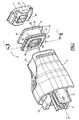
- a connector comprising a grommet-type joint (hereafter "grommet") is illustrated on Figures 1-4 .
- This connector is of a type used in an automotive application, and is intended to mate with a counterpart connector (not shown).
- the mating direction is referenced as X axis, which is oriented from the connector towards the counterpart.
- orientation or position terms used in the present description refer to this mating axis X.
- the terms “forward” or “front” read as oriented in the mating direction.
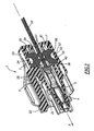
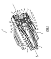
- the two-way connector 1 shown on Figures 1-4 comprises an insulating housing 3, wherein two terminal accommodating chambers 4 are formed, a grommet 5, and a rear grid 7.
- the connector 1 also comprises two terminals 9 crimped at the end of respective wires 10, and, in use, fixedly arranged in respective accommodating chambers 4 of the housing 3.
- terminals Only one of said terminals is shown on Fig. 2 and 4 , the terminals being not shown on Fig. 1 and 3 .
- the housing 3 has a generally parallelepipedic front part 21, wherein the accommodating chambers 4 are formed as through passages, a locking member 22 provided to engage a complementary locking member of the counterpart connector, and a rear skirt 23.
- Said rear skirt 23 mainly consists in a peripheral outer wall, which is generally parallelepiped-shaped and which projects rearwards from the rear end of the front part 21.
- the skirt 23 defines an inner recess, opened at the rear end, for accommodating the grommet 5 and the grid 7.
- the inner surface 24 of the skirt 23 is provided to be sealingly engaged by the outer peripheral surface of the grommet.
- the housing 3 has an inner annular shoulder 25 at the front end of the skirt, which defines a front axial abutment for the grommet 5.
- the housing 3 is preferably integrally made of a plastic material.
- the grid 7 is also preferably integrally made of a plastic material, and is essentially made as a cover having two through axial passages 34 corresponding to the chambers 4.
- the grid 7 also has locking means 35 provided to fasten the grid in the skirt 23 in its use position (see Fig. 1 ).
- the grommet 5 is overall parallelepiped-shaped, and has a front face 38 and a rear face 39. It essentially comprises a peripheral annular portion 41, a central portion 43, and flexible means 45, 47 connecting said central portion 43 to said peripheral portion 41.
- the grommet is preferably of unitary construction and made by moulding of a resilient elastomeric material.
- the peripheral annular portion 41 has an inner parallelepiped-shaped surface 51, and an outer surface 53.
- the outer surface 53 is formed with two axially spaced annular lips 55, which, in use, sealingly engage the inner surface 25 of the skirt 23.
- the lips 55 are axially separated by an annular grove 57, semi-circular in section, which is formed in the outer surface 53.
- the central portion 43 is also generally parallelepiped-shaped, and is formed with two axial through passages 64, corresponding to the respective passages 34 and accommodating chambers 4.
- Each of said passages 64 is defined by a respective sleeve 65, both sleeves constituting together the central portion 43.
- Each sleeve 65 is provided with two annular axially spaced-apart lips 67, projecting in the passage 64 to define narrow sections and, in use, sealingly engage the corresponding wire 10.
- the flexible means 45, 47 extend between the outer peripheral surface of the central portion 43 and the inner surface 24 of the peripheral portion 41.
- Preferentially flexible means include first walls 45 that extend in axial planes, i.e. planes parallel to axis X , and each sleeve 65 being connected to the peripheral portion 41 by at least one such axial wall 45.
- walls 45 are perpendicular to the inner surface 51 of annular portion 41 and for each sleeve 65, there is one wall starting from a median line of each of the sides which are facing the inner surface 51. This means that the planes defined by each wall 45 that is attaching one sleeve are going through the axis of the corresponding sleeve.
- Each sleeve 65 is connected to the peripheral portion 41 by at least a pair of coplanar opposite axial walls, which are coplanar with or centered on the respective passage axis, and a supplementary wall in a direction perpendicular to the first coplanar walls for the sleeves located at the two extremities of the central portion 43.
- This position of the walls 45 allows an easy deformation of the sleeves 65 along their diagonals which corresponds to the diagonals of the terminals, what allows those terminals to go easily through the grommet.
- the flexible walls also comprise one annular radial wall 47 which extends in a mid-section of the grommet 5, in other words at half-length of the central portion 43.
- the grommet 5 is substantially symmetrical with respect to the radial plane of the annular wall 47.
- the grommet 5 is thus provided with recesses 70 defined by the flexible walls 45, 47 between the peripheral portion 41 and the central portion 43. These recesses 70 extend from the radial wall 47 to either the front face 38 or the rear face 39, and are opened on either said front or rear face.
- the radial wall 47 constitutes a sealing wall which prevents water passage from the rear side 39 to the front side 38 of the grommet.
- the recesses 70 are blind hollow spaces in which the elastomeric material of the central portion can expand upon insertion of the terminals in the corresponding passages 64.
- the walls 45, 47 have a much lower thickness than the recesses, whereby they provide a highly flexible connection between the central portion 43 and the peripheral portion 41.
- the central portion 43 is floatably and rotatory (as a ball and socket joint) attached to the peripheral portion 41, which means that the central portion 43 is laterally or transversally displaceable with respect to the peripheral portion 41, and can also slightly rotate with respect to transversal axis to compensate misalignment and minimize the insertion force.
- the central portion 43 is biased toward a neutral position centred within the peripheral portion 41.
- the sleeves 65 are in the X direction slightly shorter than the peripheral portion 41.
- the peripheral portion 41 is in abutment against shoulder 25 there is a small clearance d in the X direction between the central portion 43 and the bottom portion of the said inner recess defined by the skirt 23.
- This allows the central portion 43 to move easily along the X axis or to rotate freely without coming into contact with the housing 3.
- a similar feature is built at the other side between the grommet and the grid 7. In another example a similar result could be obtained by having a small recess in the housing in front of the central portion 43.
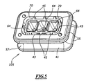
- Fig. 5 shows another example of grommet 105 which only differs from the grommet of Fig. 1-3 in that it is suitable for three-way connectors.
- the flexible axial walls 45 are symmetrically and regularly arranged on the central portion circumference, as it was the case in the preceding example.
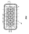
- Fig 6 shows the embodiment of a grommet 205 according to the invention for connectors with five terminals.
- the peripheral portion 41 and the central portion 43 are similar to the corresponding portions of the preceding embodiments.
- the flexible means connecting the central portion 43 to the peripheral portion 41 include walls 245 which are at an angle to the inner surface 51 of annular portion 41.
- Preferentially for each sleeve 65 there are two walls starting from a median line of each of the sides which are facing the inner surface 51, a first wall 245a starting in a first direction and a second wall 245b in a second direction symmetrical to the first one about an axial plane of the sleeve 65.
- the two walls can start from the same point at the surface 51 and connect on the sleeve at two separate lines.
- the walls when the cable is moving inside the sleeve, the movement being either a translation perpendicular to axis X or a rotation around the centre of the sleeve, the walls are mainly deformed by bending and not by stretching or compression as in the preceding embodiments, which means a reduced stiffness.
- the stiffness in translation and rotation can also be adjusted by the choice of angle and thickness of the walls.
- the invention would also be suitable for grommets having different numbers of passages for wires, and more generally would be also suitable for one- or multi-way grommets and connectors, wherein the ways are arranged in one or several rows.
Landscapes
- Connector Housings Or Holding Contact Members (AREA)
- Installation Of Indoor Wiring (AREA)
- Insulating Bodies (AREA)
Priority Applications (1)
| Application Number | Priority Date | Filing Date | Title |
|---|---|---|---|
| EP11159896A EP2339699B1 (en) | 2005-04-11 | 2006-04-11 | Grommet for electrical connector, and electrical connector comprising such a grommet |
Applications Claiming Priority (3)
| Application Number | Priority Date | Filing Date | Title |
|---|---|---|---|
| EP2005005203 | 2005-04-11 | ||
| EP11159896A EP2339699B1 (en) | 2005-04-11 | 2006-04-11 | Grommet for electrical connector, and electrical connector comprising such a grommet |
| EP06724241A EP1872446B3 (en) | 2005-04-11 | 2006-04-11 | Grommet for electrical connector, and electrical connector comprising such a grommet |
Related Parent Applications (2)
| Application Number | Title | Priority Date | Filing Date |
|---|---|---|---|
| EP06724241.2 Division | 2006-04-11 | ||
| EP06724241A Division-Into EP1872446B3 (en) | 2005-04-11 | 2006-04-11 | Grommet for electrical connector, and electrical connector comprising such a grommet |
Publications (2)
| Publication Number | Publication Date |
|---|---|
| EP2339699A1 EP2339699A1 (en) | 2011-06-29 |
| EP2339699B1 true EP2339699B1 (en) | 2012-03-21 |
Family
ID=36572478
Family Applications (2)
| Application Number | Title | Priority Date | Filing Date |
|---|---|---|---|
| EP11159896A Active EP2339699B1 (en) | 2005-04-11 | 2006-04-11 | Grommet for electrical connector, and electrical connector comprising such a grommet |
| EP06724241A Active EP1872446B3 (en) | 2005-04-11 | 2006-04-11 | Grommet for electrical connector, and electrical connector comprising such a grommet |
Family Applications After (1)
| Application Number | Title | Priority Date | Filing Date |
|---|---|---|---|
| EP06724241A Active EP1872446B3 (en) | 2005-04-11 | 2006-04-11 | Grommet for electrical connector, and electrical connector comprising such a grommet |
Country Status (7)
| Country | Link |
|---|---|
| US (1) | US7762842B2 (enExample) |
| EP (2) | EP2339699B1 (enExample) |
| JP (1) | JP2008536277A (enExample) |
| KR (1) | KR20070122536A (enExample) |
| CN (2) | CN101171725B (enExample) |
| AT (2) | ATE518281T1 (enExample) |
| WO (1) | WO2006108609A1 (enExample) |
Families Citing this family (21)
| Publication number | Priority date | Publication date | Assignee | Title |
|---|---|---|---|---|
| DE102005056328B4 (de) * | 2005-11-25 | 2008-01-31 | Woco Industrietechnik Gmbh | Dichtung, insbesondere Dichtungsmatte, für mindestens einen elektrischen Steckverbinder |
| WO2011005371A1 (en) * | 2009-07-10 | 2011-01-13 | 3M Innovative Properties Company | Sealing member |
| JP2013504847A (ja) * | 2009-09-11 | 2013-02-07 | エフシーアイ・オートモティヴ・ホールディング | マット状シールジョイント、当該シールマットを備えている電気コネクタ、及び当該シールマットの製造方法 |
| KR102162746B1 (ko) | 2009-10-21 | 2020-10-07 | 가부시키가이샤 한도오따이 에네루기 켄큐쇼 | 아날로그 회로 및 반도체 장치 |
| DE102010019600B4 (de) * | 2010-05-05 | 2012-04-26 | Tyco Electronics Amp Gmbh | Dichtelement |
| CN102906884B (zh) * | 2010-05-20 | 2015-09-02 | 行田电线株式会社 | 太阳能电池组件用端子箱 |
| JP5923898B2 (ja) * | 2011-08-30 | 2016-05-25 | ブラザー工業株式会社 | 現像装置 |
| AU2013266657C1 (en) * | 2012-05-22 | 2017-08-24 | Commscope Technologies Llc | Ruggedized fiber optic connector |
| DE102012212274B4 (de) * | 2012-07-13 | 2018-06-07 | Te Connectivity Germany Gmbh | Elektrischer Stecker mit Abdichtung und Verfahren zur Herstellung des elektrischen Steckers |
| JP6236312B2 (ja) * | 2013-12-26 | 2017-11-22 | 矢崎総業株式会社 | リアホルダ |
| JP6057304B2 (ja) * | 2014-11-26 | 2017-01-11 | 矢崎総業株式会社 | 弾性シール部材 |
| CN206610949U (zh) * | 2016-09-14 | 2017-11-03 | 泰科电子(上海)有限公司 | 用于连接导线的连接器和连接器组件 |
| KR102729125B1 (ko) * | 2017-01-20 | 2024-11-13 | 삼성전자주식회사 | 케이블 방수 장치 |
| JP2018200765A (ja) * | 2017-05-25 | 2018-12-20 | 矢崎総業株式会社 | コネクタ |
| JP6998816B2 (ja) * | 2018-03-30 | 2022-01-18 | 古河電気工業株式会社 | グロメット |
| EP3629426A1 (en) * | 2018-09-27 | 2020-04-01 | Tyco Electronics Japan G.K. | Seal member and connector assembly |
| JP6894877B2 (ja) * | 2018-10-10 | 2021-06-30 | 矢崎総業株式会社 | 防水コネクタ |
| TWM629291U (zh) | 2021-07-07 | 2022-07-11 | 大陸商富加宜電子(南通)有限公司 | 一種混合式連接器 |
| DE102021121353B3 (de) * | 2021-08-17 | 2023-02-16 | Conta-Clip Verbindungstechnik Gesellschaft mit beschränkter Haftung | Anordnung mit einer Kabelwanddurchführung für mehrere Kabel und Steckverbinder |
| CN118591946A (zh) * | 2022-01-30 | 2024-09-03 | 理想工业公司 | 具有高进入防护的电连接器 |
| DE102023123538A1 (de) * | 2023-08-31 | 2025-03-06 | Te Connectivity Solutions Gmbh | Tülle, durch die ein elektrischer Stecker hindurchführbar ist |
Family Cites Families (36)
| Publication number | Priority date | Publication date | Assignee | Title |
|---|---|---|---|---|
| GB8404107D0 (en) * | 1984-02-16 | 1984-03-21 | Allied Corp | Grommet for connectors |
| US4713021A (en) * | 1985-05-17 | 1987-12-15 | Amp Incorporated | Sealed electrical connector and method of using same |
| US4648672A (en) * | 1985-05-17 | 1987-03-10 | Amp Incorporated | Wire seal |
| US4690478A (en) * | 1986-04-10 | 1987-09-01 | United Technologies Automotive, Inc. | Sealed electrical connector assembly |
| US4973266A (en) * | 1988-08-09 | 1990-11-27 | Dill Products Incorporated | Combined terminal secondary lock and seal |
| DE69033684T2 (de) * | 1989-10-24 | 2001-06-07 | The Whitaker Corp., Wilmington | Abgedichteter elektrischer Verbinder |
| DE69205511T2 (de) * | 1991-02-15 | 1996-04-11 | Framatome Connectors Connectral, Suresnes | Elektrischer steckverbinder mit abgedichteter drahtdurchführung. |
| JP2905388B2 (ja) * | 1994-03-24 | 1999-06-14 | 矢崎総業株式会社 | コネクタの防水構造 |
| JP3317587B2 (ja) * | 1994-07-19 | 2002-08-26 | タイコエレクトロニクスアンプ株式会社 | 防水栓及びこれを使用した防水コネクタ |
| US5667406A (en) * | 1994-07-27 | 1997-09-16 | Sumitomo Wiring Systems, Ltd. | Waterproof seal for connector and method for forming same |
| JP3109794B2 (ja) * | 1994-09-27 | 2000-11-20 | ヒロセ電機株式会社 | 防水コネクタ |
| JPH0982402A (ja) * | 1995-09-07 | 1997-03-28 | Yazaki Corp | シールパッキン及び機器直付けコネクタ |
| US5871373A (en) * | 1996-02-23 | 1999-02-16 | Labinal Components And Systems, Inc. | Electrical connector |
| JPH10223303A (ja) * | 1997-02-06 | 1998-08-21 | Yazaki Corp | 防水コネクタ用ゴム栓 |
| WO1998037597A1 (en) * | 1997-02-19 | 1998-08-27 | The Whitaker Corporation | Electrical connector with a family seal, and family seal |
| US6176739B1 (en) * | 1997-02-20 | 2001-01-23 | The Whitaker Corporation | Sealed electrical conductor assembly |
| JP2978144B2 (ja) * | 1997-07-01 | 1999-11-15 | 日本アンテナ株式会社 | ダミー内蔵同軸コネクター |
| JP3276907B2 (ja) * | 1997-11-26 | 2002-04-22 | 本田技研工業株式会社 | 防水コネクタ |
| JPH11250976A (ja) * | 1998-03-03 | 1999-09-17 | Japan Aviation Electronics Ind Ltd | 防水型同軸レセプタクルコネクタ |
| US6114629A (en) * | 1998-09-28 | 2000-09-05 | The United States Of America As Represented By The Secretary Of The Navy | Grommet having metal insert |
| JP2000353567A (ja) * | 1999-06-10 | 2000-12-19 | Yazaki Corp | 防水コネクタ |
| JP3691288B2 (ja) * | 1999-06-10 | 2005-09-07 | 矢崎総業株式会社 | 防水コネクタ |
| JP3691300B2 (ja) * | 1999-08-26 | 2005-09-07 | 矢崎総業株式会社 | 防水コネクタ |
| JP3380528B2 (ja) * | 2000-07-13 | 2003-02-24 | 日本圧着端子製造株式会社 | 防水コネクタ |
| JP2002117930A (ja) * | 2000-10-06 | 2002-04-19 | Tyco Electronics Amp Kk | 防水グロメット |
| JP2002231375A (ja) * | 2001-01-30 | 2002-08-16 | Yazaki Corp | 補機モジュールの封止構造 |
| JP3991670B2 (ja) * | 2001-12-06 | 2007-10-17 | 住友電装株式会社 | コネクタ |
| US6814632B1 (en) * | 2002-06-04 | 2004-11-09 | Raytheon Company | Electrical connector system having contact body with integral nonmetallic sleeve |
| FR2844644B1 (fr) * | 2002-09-12 | 2006-04-28 | Framatome Connectors Int | Systeme d'etancheite pour connecteur electrique multibroche |
| US6986677B2 (en) * | 2003-06-25 | 2006-01-17 | Tyco Electronics Nederland B.V. | Seal carrying electrical contact |
| EP1555728B1 (de) * | 2004-01-16 | 2007-03-14 | Delphi Technologies, Inc. | Elektrischer Verbinder |
| JP2005317385A (ja) * | 2004-04-28 | 2005-11-10 | Tyco Electronics Amp Kk | 防水型コネクタ用シール部材及び防水型コネクタ |
| JP2006140019A (ja) * | 2004-11-11 | 2006-06-01 | Tyco Electronics Amp Kk | 防水コネクタおよびシール部材 |
| JP4761931B2 (ja) * | 2005-10-27 | 2011-08-31 | 矢崎総業株式会社 | 端子可動コネクタ |
| US7115822B1 (en) * | 2006-02-21 | 2006-10-03 | Joy Mm Delaware, Inc. | Indirect entry cable gland assembly |
| US7371115B1 (en) * | 2006-12-15 | 2008-05-13 | Delphi Technologies, Inc. | Mat seal device |
-
2006
- 2006-04-11 AT AT06724241T patent/ATE518281T1/de not_active IP Right Cessation
- 2006-04-11 JP JP2008505796A patent/JP2008536277A/ja active Pending
- 2006-04-11 CN CN2006800156899A patent/CN101171725B/zh active Active
- 2006-04-11 EP EP11159896A patent/EP2339699B1/en active Active
- 2006-04-11 US US11/918,265 patent/US7762842B2/en active Active
- 2006-04-11 KR KR1020077026089A patent/KR20070122536A/ko not_active Withdrawn
- 2006-04-11 EP EP06724241A patent/EP1872446B3/en active Active
- 2006-04-11 WO PCT/EP2006/003320 patent/WO2006108609A1/en not_active Ceased
- 2006-04-11 CN CN201110184701.1A patent/CN102394438B/zh active Active
- 2006-04-11 AT AT11159896T patent/ATE550810T1/de active
Also Published As
| Publication number | Publication date |
|---|---|
| CN102394438A (zh) | 2012-03-28 |
| CN101171725B (zh) | 2012-02-15 |
| CN101171725A (zh) | 2008-04-30 |
| EP1872446A1 (en) | 2008-01-02 |
| US7762842B2 (en) | 2010-07-27 |
| KR20070122536A (ko) | 2007-12-31 |
| ATE518281T1 (de) | 2011-08-15 |
| JP2008536277A (ja) | 2008-09-04 |
| CN102394438B (zh) | 2015-01-07 |
| US20090215312A1 (en) | 2009-08-27 |
| ATE550810T1 (de) | 2012-04-15 |
| EP1872446B3 (en) | 2012-11-07 |
| EP2339699A1 (en) | 2011-06-29 |
| EP1872446B1 (en) | 2011-07-27 |
| WO2006108609A1 (en) | 2006-10-19 |
Similar Documents
| Publication | Publication Date | Title |
|---|---|---|
| EP2339699B1 (en) | Grommet for electrical connector, and electrical connector comprising such a grommet | |
| US4713021A (en) | Sealed electrical connector and method of using same | |
| US4832615A (en) | Sealed connector having unitary molded housing | |
| US4637674A (en) | Annular connector seal | |
| EP1872445B1 (en) | Improved grommet-type joint for electrical connector, and electrical connector comprising such a joint | |
| US6058977A (en) | Rubber stopper for waterproof connector | |
| US6059594A (en) | Sealed electrical connector | |
| KR102060894B1 (ko) | 밀봉된 전기 커넥터 조립체 및 와이어 밀봉부 | |
| US20020001987A1 (en) | Connector | |
| EP0221952B1 (en) | Wire seal | |
| CA2954065A1 (en) | Connector assembly | |
| EP3783747A1 (en) | Seal part | |
| JP2021034153A5 (ja) | コネクタ用シール構造及びコネクタ | |
| US20220320790A1 (en) | Elastomer seal spring | |
| US5888107A (en) | Male contact | |
| CN105390856A (zh) | 连接器 | |
| US20010012717A1 (en) | Connector | |
| EP0529463B1 (en) | Seals for an electrical connector | |
| US20250323452A1 (en) | Seal For A Connector | |
| US20240030643A1 (en) | Connector assembly with terminal position assurance and blocking feature | |
| US20250260194A1 (en) | Cable assembly including a hood adapter and hood | |
| GB2077055A (en) | Electrical connector assembly | |
| US20090042429A1 (en) | Sealed Connection Device and Sealed Connector Counterpart | |
| JP2025067288A (ja) | 端子金具 | |
| WO2007128337A1 (en) | Electrical connector |
Legal Events
| Date | Code | Title | Description |
|---|---|---|---|
| PUAI | Public reference made under article 153(3) epc to a published international application that has entered the european phase |
Free format text: ORIGINAL CODE: 0009012 |
|
| 17P | Request for examination filed |
Effective date: 20110325 |
|
| AC | Divisional application: reference to earlier application |
Ref document number: 1872446 Country of ref document: EP Kind code of ref document: P |
|
| AK | Designated contracting states |
Kind code of ref document: A1 Designated state(s): AT BE BG CH CY CZ DE DK EE ES FI FR GB GR HU IE IS IT LI LT LU LV MC NL PL PT RO SE SI SK TR |
|
| GRAP | Despatch of communication of intention to grant a patent |
Free format text: ORIGINAL CODE: EPIDOSNIGR1 |
|
| RIC1 | Information provided on ipc code assigned before grant |
Ipc: H01R 13/52 20060101AFI20110726BHEP |
|
| GRAS | Grant fee paid |
Free format text: ORIGINAL CODE: EPIDOSNIGR3 |
|
| GRAA | (expected) grant |
Free format text: ORIGINAL CODE: 0009210 |
|
| RAP1 | Party data changed (applicant data changed or rights of an application transferred) |
Owner name: FCI AUTOMOTIVE HOLDING |
|
| AC | Divisional application: reference to earlier application |
Ref document number: 1872446 Country of ref document: EP Kind code of ref document: P |
|
| AK | Designated contracting states |
Kind code of ref document: B1 Designated state(s): AT BE BG CH CY CZ DE DK EE ES FI FR GB GR HU IE IS IT LI LT LU LV MC NL PL PT RO SE SI SK TR |
|
| REG | Reference to a national code |
Ref country code: GB Ref legal event code: FG4D |
|
| REG | Reference to a national code |
Ref country code: CH Ref legal event code: EP |
|
| REG | Reference to a national code |
Ref country code: IE Ref legal event code: FG4D |
|
| REG | Reference to a national code |
Ref country code: AT Ref legal event code: REF Ref document number: 550810 Country of ref document: AT Kind code of ref document: T Effective date: 20120415 |
|
| REG | Reference to a national code |
Ref country code: DE Ref legal event code: R096 Ref document number: 602006028401 Country of ref document: DE Effective date: 20120524 |
|
| REG | Reference to a national code |
Ref country code: NL Ref legal event code: VDEP Effective date: 20120321 |
|
| PG25 | Lapsed in a contracting state [announced via postgrant information from national office to epo] |
Ref country code: LT Free format text: LAPSE BECAUSE OF FAILURE TO SUBMIT A TRANSLATION OF THE DESCRIPTION OR TO PAY THE FEE WITHIN THE PRESCRIBED TIME-LIMIT Effective date: 20120321 |
|
| LTIE | Lt: invalidation of european patent or patent extension |
Effective date: 20120321 |
|
| PG25 | Lapsed in a contracting state [announced via postgrant information from national office to epo] |
Ref country code: LV Free format text: LAPSE BECAUSE OF FAILURE TO SUBMIT A TRANSLATION OF THE DESCRIPTION OR TO PAY THE FEE WITHIN THE PRESCRIBED TIME-LIMIT Effective date: 20120321 Ref country code: FI Free format text: LAPSE BECAUSE OF FAILURE TO SUBMIT A TRANSLATION OF THE DESCRIPTION OR TO PAY THE FEE WITHIN THE PRESCRIBED TIME-LIMIT Effective date: 20120321 Ref country code: GR Free format text: LAPSE BECAUSE OF FAILURE TO SUBMIT A TRANSLATION OF THE DESCRIPTION OR TO PAY THE FEE WITHIN THE PRESCRIBED TIME-LIMIT Effective date: 20120622 |
|
| REG | Reference to a national code |
Ref country code: AT Ref legal event code: MK05 Ref document number: 550810 Country of ref document: AT Kind code of ref document: T Effective date: 20120321 |
|
| PG25 | Lapsed in a contracting state [announced via postgrant information from national office to epo] |
Ref country code: CY Free format text: LAPSE BECAUSE OF FAILURE TO SUBMIT A TRANSLATION OF THE DESCRIPTION OR TO PAY THE FEE WITHIN THE PRESCRIBED TIME-LIMIT Effective date: 20120321 |
|
| PG25 | Lapsed in a contracting state [announced via postgrant information from national office to epo] |
Ref country code: EE Free format text: LAPSE BECAUSE OF FAILURE TO SUBMIT A TRANSLATION OF THE DESCRIPTION OR TO PAY THE FEE WITHIN THE PRESCRIBED TIME-LIMIT Effective date: 20120321 Ref country code: RO Free format text: LAPSE BECAUSE OF FAILURE TO SUBMIT A TRANSLATION OF THE DESCRIPTION OR TO PAY THE FEE WITHIN THE PRESCRIBED TIME-LIMIT Effective date: 20120321 Ref country code: IS Free format text: LAPSE BECAUSE OF FAILURE TO SUBMIT A TRANSLATION OF THE DESCRIPTION OR TO PAY THE FEE WITHIN THE PRESCRIBED TIME-LIMIT Effective date: 20120721 Ref country code: BE Free format text: LAPSE BECAUSE OF FAILURE TO SUBMIT A TRANSLATION OF THE DESCRIPTION OR TO PAY THE FEE WITHIN THE PRESCRIBED TIME-LIMIT Effective date: 20120321 Ref country code: SE Free format text: LAPSE BECAUSE OF FAILURE TO SUBMIT A TRANSLATION OF THE DESCRIPTION OR TO PAY THE FEE WITHIN THE PRESCRIBED TIME-LIMIT Effective date: 20120321 Ref country code: SI Free format text: LAPSE BECAUSE OF FAILURE TO SUBMIT A TRANSLATION OF THE DESCRIPTION OR TO PAY THE FEE WITHIN THE PRESCRIBED TIME-LIMIT Effective date: 20120321 Ref country code: PL Free format text: LAPSE BECAUSE OF FAILURE TO SUBMIT A TRANSLATION OF THE DESCRIPTION OR TO PAY THE FEE WITHIN THE PRESCRIBED TIME-LIMIT Effective date: 20120321 Ref country code: CZ Free format text: LAPSE BECAUSE OF FAILURE TO SUBMIT A TRANSLATION OF THE DESCRIPTION OR TO PAY THE FEE WITHIN THE PRESCRIBED TIME-LIMIT Effective date: 20120321 |
|
| PG25 | Lapsed in a contracting state [announced via postgrant information from national office to epo] |
Ref country code: SK Free format text: LAPSE BECAUSE OF FAILURE TO SUBMIT A TRANSLATION OF THE DESCRIPTION OR TO PAY THE FEE WITHIN THE PRESCRIBED TIME-LIMIT Effective date: 20120321 Ref country code: MC Free format text: LAPSE BECAUSE OF NON-PAYMENT OF DUE FEES Effective date: 20120430 Ref country code: PT Free format text: LAPSE BECAUSE OF FAILURE TO SUBMIT A TRANSLATION OF THE DESCRIPTION OR TO PAY THE FEE WITHIN THE PRESCRIBED TIME-LIMIT Effective date: 20120723 |
|
| REG | Reference to a national code |
Ref country code: CH Ref legal event code: PL |
|
| REG | Reference to a national code |
Ref country code: IE Ref legal event code: MM4A |
|
| PLBE | No opposition filed within time limit |
Free format text: ORIGINAL CODE: 0009261 |
|
| STAA | Information on the status of an ep patent application or granted ep patent |
Free format text: STATUS: NO OPPOSITION FILED WITHIN TIME LIMIT |
|
| PG25 | Lapsed in a contracting state [announced via postgrant information from national office to epo] |
Ref country code: DK Free format text: LAPSE BECAUSE OF FAILURE TO SUBMIT A TRANSLATION OF THE DESCRIPTION OR TO PAY THE FEE WITHIN THE PRESCRIBED TIME-LIMIT Effective date: 20120321 Ref country code: AT Free format text: LAPSE BECAUSE OF FAILURE TO SUBMIT A TRANSLATION OF THE DESCRIPTION OR TO PAY THE FEE WITHIN THE PRESCRIBED TIME-LIMIT Effective date: 20120321 Ref country code: LI Free format text: LAPSE BECAUSE OF NON-PAYMENT OF DUE FEES Effective date: 20120430 Ref country code: IE Free format text: LAPSE BECAUSE OF NON-PAYMENT OF DUE FEES Effective date: 20120411 Ref country code: NL Free format text: LAPSE BECAUSE OF FAILURE TO SUBMIT A TRANSLATION OF THE DESCRIPTION OR TO PAY THE FEE WITHIN THE PRESCRIBED TIME-LIMIT Effective date: 20120321 Ref country code: CH Free format text: LAPSE BECAUSE OF NON-PAYMENT OF DUE FEES Effective date: 20120430 |
|
| 26N | No opposition filed |
Effective date: 20130102 |
|
| GBPC | Gb: european patent ceased through non-payment of renewal fee |
Effective date: 20120621 |
|
| REG | Reference to a national code |
Ref country code: DE Ref legal event code: R097 Ref document number: 602006028401 Country of ref document: DE Effective date: 20130102 |
|
| PG25 | Lapsed in a contracting state [announced via postgrant information from national office to epo] |
Ref country code: GB Free format text: LAPSE BECAUSE OF NON-PAYMENT OF DUE FEES Effective date: 20120621 |
|
| PG25 | Lapsed in a contracting state [announced via postgrant information from national office to epo] |
Ref country code: BG Free format text: LAPSE BECAUSE OF FAILURE TO SUBMIT A TRANSLATION OF THE DESCRIPTION OR TO PAY THE FEE WITHIN THE PRESCRIBED TIME-LIMIT Effective date: 20120621 |
|
| PG25 | Lapsed in a contracting state [announced via postgrant information from national office to epo] |
Ref country code: ES Free format text: LAPSE BECAUSE OF FAILURE TO SUBMIT A TRANSLATION OF THE DESCRIPTION OR TO PAY THE FEE WITHIN THE PRESCRIBED TIME-LIMIT Effective date: 20120702 |
|
| PG25 | Lapsed in a contracting state [announced via postgrant information from national office to epo] |
Ref country code: TR Free format text: LAPSE BECAUSE OF FAILURE TO SUBMIT A TRANSLATION OF THE DESCRIPTION OR TO PAY THE FEE WITHIN THE PRESCRIBED TIME-LIMIT Effective date: 20120321 |
|
| PG25 | Lapsed in a contracting state [announced via postgrant information from national office to epo] |
Ref country code: LU Free format text: LAPSE BECAUSE OF NON-PAYMENT OF DUE FEES Effective date: 20120411 |
|
| PG25 | Lapsed in a contracting state [announced via postgrant information from national office to epo] |
Ref country code: HU Free format text: LAPSE BECAUSE OF FAILURE TO SUBMIT A TRANSLATION OF THE DESCRIPTION OR TO PAY THE FEE WITHIN THE PRESCRIBED TIME-LIMIT Effective date: 20060411 |
|
| REG | Reference to a national code |
Ref country code: FR Ref legal event code: TP Owner name: DELPHI INTERNATIONAL OPERATIONS LUXEMBOURG S.A, LU Effective date: 20140715 |
|
| REG | Reference to a national code |
Ref country code: FR Ref legal event code: PLFP Year of fee payment: 11 |
|
| REG | Reference to a national code |
Ref country code: FR Ref legal event code: PLFP Year of fee payment: 12 |
|
| REG | Reference to a national code |
Ref country code: FR Ref legal event code: PLFP Year of fee payment: 13 |
|
| REG | Reference to a national code |
Ref country code: DE Ref legal event code: R081 Ref document number: 602006028401 Country of ref document: DE Owner name: APTIV TECHNOLOGIES LIMITED, BB Free format text: FORMER OWNER: FCI AUTOMOTIVE HOLDING, GUYANCOURT, FR |
|
| P01 | Opt-out of the competence of the unified patent court (upc) registered |
Effective date: 20230519 |
|
| PGFP | Annual fee paid to national office [announced via postgrant information from national office to epo] |
Ref country code: FR Payment date: 20250314 Year of fee payment: 20 |
|
| REG | Reference to a national code |
Ref country code: DE Ref legal event code: R081 Ref document number: 602006028401 Country of ref document: DE Owner name: APTIV TECHNOLOGIES AG, CH Free format text: FORMER OWNER: APTIV TECHNOLOGIES LIMITED, ST. MICHAEL, BB |
|
| PGFP | Annual fee paid to national office [announced via postgrant information from national office to epo] |
Ref country code: DE Payment date: 20250313 Year of fee payment: 20 |
|
| PGFP | Annual fee paid to national office [announced via postgrant information from national office to epo] |
Ref country code: IT Payment date: 20250313 Year of fee payment: 20 |