EP2337984B1 - Vessel with a reinforced corrugated membrane - Google Patents
Vessel with a reinforced corrugated membrane Download PDFInfo
- Publication number
- EP2337984B1 EP2337984B1 EP09784452.6A EP09784452A EP2337984B1 EP 2337984 B1 EP2337984 B1 EP 2337984B1 EP 09784452 A EP09784452 A EP 09784452A EP 2337984 B1 EP2337984 B1 EP 2337984B1
- Authority
- EP
- European Patent Office
- Prior art keywords
- tank
- reinforcing element
- membrane
- reinforcing
- corrugation
- Prior art date
- Legal status (The legal status is an assumption and is not a legal conclusion. Google has not performed a legal analysis and makes no representation as to the accuracy of the status listed.)
- Active
Links
- 239000012528 membrane Substances 0.000 title claims description 43
- 230000003014 reinforcing effect Effects 0.000 claims description 83
- 239000011120 plywood Substances 0.000 claims description 11
- 239000002184 metal Substances 0.000 claims description 6
- 239000004417 polycarbonate Substances 0.000 claims description 6
- 229920000515 polycarbonate Polymers 0.000 claims description 6
- 239000000463 material Substances 0.000 claims description 4
- 239000004697 Polyetherimide Substances 0.000 claims description 3
- 239000004698 Polyethylene Substances 0.000 claims description 3
- 239000004794 expanded polystyrene Substances 0.000 claims description 3
- 238000007667 floating Methods 0.000 claims description 3
- 239000003365 glass fiber Substances 0.000 claims description 3
- 229920001601 polyetherimide Polymers 0.000 claims description 3
- -1 polyethylene Polymers 0.000 claims description 3
- 229920000573 polyethylene Polymers 0.000 claims description 3
- 229910001220 stainless steel Inorganic materials 0.000 claims description 3
- 239000010935 stainless steel Substances 0.000 claims description 3
- 238000010276 construction Methods 0.000 claims 1
- 230000004888 barrier function Effects 0.000 description 5
- 239000007789 gas Substances 0.000 description 5
- 230000002706 hydrostatic effect Effects 0.000 description 4
- 239000004033 plastic Substances 0.000 description 4
- 229920003023 plastic Polymers 0.000 description 4
- 230000008602 contraction Effects 0.000 description 3
- 230000000694 effects Effects 0.000 description 3
- 239000003949 liquefied natural gas Substances 0.000 description 3
- 238000004519 manufacturing process Methods 0.000 description 3
- 238000009826 distribution Methods 0.000 description 2
- 238000003754 machining Methods 0.000 description 2
- 230000002787 reinforcement Effects 0.000 description 2
- 238000004088 simulation Methods 0.000 description 2
- 238000001125 extrusion Methods 0.000 description 1
- 238000002347 injection Methods 0.000 description 1
- 239000007924 injection Substances 0.000 description 1
- 238000009434 installation Methods 0.000 description 1
- 238000000034 method Methods 0.000 description 1
- 238000000465 moulding Methods 0.000 description 1
- 238000007789 sealing Methods 0.000 description 1
- 239000000243 solution Substances 0.000 description 1
- 238000003466 welding Methods 0.000 description 1
Images


Classifications
-
- F—MECHANICAL ENGINEERING; LIGHTING; HEATING; WEAPONS; BLASTING
- F17—STORING OR DISTRIBUTING GASES OR LIQUIDS
- F17C—VESSELS FOR CONTAINING OR STORING COMPRESSED, LIQUEFIED OR SOLIDIFIED GASES; FIXED-CAPACITY GAS-HOLDERS; FILLING VESSELS WITH, OR DISCHARGING FROM VESSELS, COMPRESSED, LIQUEFIED, OR SOLIDIFIED GASES
- F17C3/00—Vessels not under pressure
- F17C3/02—Vessels not under pressure with provision for thermal insulation
- F17C3/025—Bulk storage in barges or on ships
- F17C3/027—Wallpanels for so-called membrane tanks
-
- F—MECHANICAL ENGINEERING; LIGHTING; HEATING; WEAPONS; BLASTING
- F17—STORING OR DISTRIBUTING GASES OR LIQUIDS
- F17C—VESSELS FOR CONTAINING OR STORING COMPRESSED, LIQUEFIED OR SOLIDIFIED GASES; FIXED-CAPACITY GAS-HOLDERS; FILLING VESSELS WITH, OR DISCHARGING FROM VESSELS, COMPRESSED, LIQUEFIED, OR SOLIDIFIED GASES
- F17C2201/00—Vessel construction, in particular geometry, arrangement or size
- F17C2201/01—Shape
- F17C2201/0147—Shape complex
- F17C2201/0157—Polygonal
-
- F—MECHANICAL ENGINEERING; LIGHTING; HEATING; WEAPONS; BLASTING
- F17—STORING OR DISTRIBUTING GASES OR LIQUIDS
- F17C—VESSELS FOR CONTAINING OR STORING COMPRESSED, LIQUEFIED OR SOLIDIFIED GASES; FIXED-CAPACITY GAS-HOLDERS; FILLING VESSELS WITH, OR DISCHARGING FROM VESSELS, COMPRESSED, LIQUEFIED, OR SOLIDIFIED GASES
- F17C2201/00—Vessel construction, in particular geometry, arrangement or size
- F17C2201/05—Size
- F17C2201/052—Size large (>1000 m3)
-
- F—MECHANICAL ENGINEERING; LIGHTING; HEATING; WEAPONS; BLASTING
- F17—STORING OR DISTRIBUTING GASES OR LIQUIDS
- F17C—VESSELS FOR CONTAINING OR STORING COMPRESSED, LIQUEFIED OR SOLIDIFIED GASES; FIXED-CAPACITY GAS-HOLDERS; FILLING VESSELS WITH, OR DISCHARGING FROM VESSELS, COMPRESSED, LIQUEFIED, OR SOLIDIFIED GASES
- F17C2203/00—Vessel construction, in particular walls or details thereof
- F17C2203/01—Reinforcing or suspension means
- F17C2203/011—Reinforcing means
- F17C2203/012—Reinforcing means on or in the wall, e.g. ribs
-
- F—MECHANICAL ENGINEERING; LIGHTING; HEATING; WEAPONS; BLASTING
- F17—STORING OR DISTRIBUTING GASES OR LIQUIDS
- F17C—VESSELS FOR CONTAINING OR STORING COMPRESSED, LIQUEFIED OR SOLIDIFIED GASES; FIXED-CAPACITY GAS-HOLDERS; FILLING VESSELS WITH, OR DISCHARGING FROM VESSELS, COMPRESSED, LIQUEFIED, OR SOLIDIFIED GASES
- F17C2209/00—Vessel construction, in particular methods of manufacturing
- F17C2209/23—Manufacturing of particular parts or at special locations
- F17C2209/232—Manufacturing of particular parts or at special locations of walls
-
- F—MECHANICAL ENGINEERING; LIGHTING; HEATING; WEAPONS; BLASTING
- F17—STORING OR DISTRIBUTING GASES OR LIQUIDS
- F17C—VESSELS FOR CONTAINING OR STORING COMPRESSED, LIQUEFIED OR SOLIDIFIED GASES; FIXED-CAPACITY GAS-HOLDERS; FILLING VESSELS WITH, OR DISCHARGING FROM VESSELS, COMPRESSED, LIQUEFIED, OR SOLIDIFIED GASES
- F17C2221/00—Handled fluid, in particular type of fluid
- F17C2221/03—Mixtures
- F17C2221/032—Hydrocarbons
- F17C2221/033—Methane, e.g. natural gas, CNG, LNG, GNL, GNC, PLNG
-
- F—MECHANICAL ENGINEERING; LIGHTING; HEATING; WEAPONS; BLASTING
- F17—STORING OR DISTRIBUTING GASES OR LIQUIDS
- F17C—VESSELS FOR CONTAINING OR STORING COMPRESSED, LIQUEFIED OR SOLIDIFIED GASES; FIXED-CAPACITY GAS-HOLDERS; FILLING VESSELS WITH, OR DISCHARGING FROM VESSELS, COMPRESSED, LIQUEFIED, OR SOLIDIFIED GASES
- F17C2223/00—Handled fluid before transfer, i.e. state of fluid when stored in the vessel or before transfer from the vessel
- F17C2223/01—Handled fluid before transfer, i.e. state of fluid when stored in the vessel or before transfer from the vessel characterised by the phase
- F17C2223/0146—Two-phase
- F17C2223/0153—Liquefied gas, e.g. LPG, GPL
- F17C2223/0161—Liquefied gas, e.g. LPG, GPL cryogenic, e.g. LNG, GNL, PLNG
-
- F—MECHANICAL ENGINEERING; LIGHTING; HEATING; WEAPONS; BLASTING
- F17—STORING OR DISTRIBUTING GASES OR LIQUIDS
- F17C—VESSELS FOR CONTAINING OR STORING COMPRESSED, LIQUEFIED OR SOLIDIFIED GASES; FIXED-CAPACITY GAS-HOLDERS; FILLING VESSELS WITH, OR DISCHARGING FROM VESSELS, COMPRESSED, LIQUEFIED, OR SOLIDIFIED GASES
- F17C2223/00—Handled fluid before transfer, i.e. state of fluid when stored in the vessel or before transfer from the vessel
- F17C2223/03—Handled fluid before transfer, i.e. state of fluid when stored in the vessel or before transfer from the vessel characterised by the pressure level
- F17C2223/033—Small pressure, e.g. for liquefied gas
-
- F—MECHANICAL ENGINEERING; LIGHTING; HEATING; WEAPONS; BLASTING
- F17—STORING OR DISTRIBUTING GASES OR LIQUIDS
- F17C—VESSELS FOR CONTAINING OR STORING COMPRESSED, LIQUEFIED OR SOLIDIFIED GASES; FIXED-CAPACITY GAS-HOLDERS; FILLING VESSELS WITH, OR DISCHARGING FROM VESSELS, COMPRESSED, LIQUEFIED, OR SOLIDIFIED GASES
- F17C2260/00—Purposes of gas storage and gas handling
- F17C2260/01—Improving mechanical properties or manufacturing
- F17C2260/011—Improving strength
-
- F—MECHANICAL ENGINEERING; LIGHTING; HEATING; WEAPONS; BLASTING
- F17—STORING OR DISTRIBUTING GASES OR LIQUIDS
- F17C—VESSELS FOR CONTAINING OR STORING COMPRESSED, LIQUEFIED OR SOLIDIFIED GASES; FIXED-CAPACITY GAS-HOLDERS; FILLING VESSELS WITH, OR DISCHARGING FROM VESSELS, COMPRESSED, LIQUEFIED, OR SOLIDIFIED GASES
- F17C2270/00—Applications
- F17C2270/01—Applications for fluid transport or storage
- F17C2270/0102—Applications for fluid transport or storage on or in the water
- F17C2270/0105—Ships
- F17C2270/0107—Wall panels
Landscapes
- Engineering & Computer Science (AREA)
- Mechanical Engineering (AREA)
- Physics & Mathematics (AREA)
- Thermal Sciences (AREA)
- General Engineering & Computer Science (AREA)
- Filling Or Discharging Of Gas Storage Vessels (AREA)
- Separation Using Semi-Permeable Membranes (AREA)
- Chemical & Material Sciences (AREA)
- Combustion & Propulsion (AREA)
- Ocean & Marine Engineering (AREA)
Description
La présente invention se rapporte à une cuve étanche. En particulier, la présente invention se rapporte à une cuve étanche et thermiquement isolée destinée au transport de gaz naturel liquéfié (GNL) par navire.The present invention relates to a sealed tank. In particular, the present invention relates to a sealed and thermally insulated tank for the transport of liquefied natural gas (LNG) by ship.
Le document
En fonctionnement, des contraintes mécaniques sont générées dans la membrane. Ces contraintes ont plusieurs sources : la rétraction thermique lors de la mise à froid de la cuve, l'effet de la poutre du navire, la pression hydrostatique due au chargement, ainsi que la pression dynamique due au mouvement de la cargaison, notamment en raison de la houle.In operation, mechanical stresses are generated in the membrane. These constraints have several sources: the thermal shrinkage during the cold setting of the tank, the effect of the beam of the ship, the hydrostatic pressure due to loading, as well as the dynamic pressure due to the movement of the cargo, in particular because of the swell.
Les ondes prévues sur les plaques métalliques de la membrane sont destinées à permettre à la membrane de se déformer pour limiter les contraintes engendrées par la rétraction thermique et l'effet de la poutre du navire.The waves provided on the metal plates of the membrane are intended to allow the membrane to deform to limit the stresses generated by the thermal shrinkage and the effect of the beam of the ship.
On a constaté que la pression dynamique pouvait provoquer des déformations plastiques des ondes. Or, à l'usage, de telles déformations peuvent conduire à dégrader la flexibilité des plaques et nuire à l'étanchéité de la membrane, notamment au niveau des jonctions entre plaques.It has been found that the dynamic pressure can cause plastic deformations of the waves. However, in use, such deformations can lead to degrade the flexibility of the plates and affect the sealing of the membrane, especially at the junctions between plates.
Pour augmenter la résistance à la pression de la membrane et limiter les déformations plastiques, le document
Cependant, il peut être intéressant d'accroitre encore la résistance à la pression de la membrane.However, it may be advantageous to further increase the pressure resistance of the membrane.
Un problème que la présente invention propose de résoudre est de fournir une cuve qui ne présente pas au moins certains des inconvénients précités de l'art antérieur. En particulier, un but de l'invention est d'améliorer la résistance à la pression de la membrane, afin d'éviter ou d'en limiter les déformations plastiques.A problem that the present invention proposes to solve is to provide a vessel that does not exhibit at least some of the aforementioned drawbacks of the prior art. In particular, an object of the invention is to improve the pressure resistance of the membrane, in order to avoid or limit the plastic deformations.
La solution proposée par l'invention est une cuve étanche, dont au moins une paroi comprend une membrane étanche et conforme à la revendication 1.The solution proposed by the invention is a sealed tank, at least one wall comprises a waterproof membrane and according to
On a constaté qu'un tel élément de renfort permet de limiter les contraintes générées dans la membrane. Bien entendu, la membrane peut comprendre plusieurs plaques, la plaque peut présenter plusieurs ondes, et un élément de renfort peut être agencé sous une ou plusieurs ondes d'une ou plusieurs plaques. Le support peut être par exemple une couche thermiquement isolante, et plus précisément un panneau en contreplaqué d'une couche thermiquement isolante.It has been found that such a reinforcing element makes it possible to limit the stresses generated in the membrane. Of course, the membrane may comprise several plates, the plate may have several waves, and a reinforcing element may be arranged under one or more waves of one or more plates. The support may be for example a thermally insulating layer, and more specifically a plywood panel with a thermally insulating layer.
Selon un mode de réalisation, l'élément de renfort présente un passage interne qui permet à du gaz de circuler entre l'onde et le support en traversant l'élément de renfort.According to one embodiment, the reinforcing element has an internal passage that allows gas to flow between the wave and the support through the reinforcing element.
Selon un mode de réalisation, un passage externe permet à du gaz de circuler entre l'onde et le support en contournant l'élément de renfort.According to one embodiment, an external passage allows gas to flow between the wave and the support bypassing the reinforcing element.
Avantageusement, l'élément de renfort est réalisé en un matériau choisi parmi : le contreplaqué, le polyéthylène, le polycarbonate, le polycarbonate renforcé de fibres de verres, le polyéther imide, et le polystyrène expansé.Advantageously, the reinforcing element is made of a material chosen from: plywood, polyethylene, polycarbonate, polycarbonate reinforced with glass fibers, polyether imide, and expanded polystyrene.
Selon un mode de réalisation, l'élément de renfort comprend une enveloppe externe dont la forme correspond sensiblement à la forme de l'onde.According to one embodiment, the reinforcing element comprises an outer envelope whose shape corresponds substantially to the shape of the wave.
De préférence, l'élément de renfort comprend au moins un voile de renfort à l'intérieur de ladite enveloppe.Preferably, the reinforcing element comprises at least one reinforcing web inside said envelope.
Avantageusement, en l'absence de produit contenu dans la cuve, la distance minimale entre l'élément de renfort et l'onde est comprise entre 0 % et 5 % de la hauteur de l'onde.Advantageously, in the absence of product contained in the tank, the minimum distance between the reinforcing element and the wave is between 0% and 5% of the height of the wave.
De préférence, la plaque présente une première série d'ondes parallèles entre elles, et une deuxième série d'ondes parallèles entre elles et transverses aux ondes de la première série, l'élément de renfort étant inséré sous une onde de la première série. Bien entendu, plusieurs éléments de renfort peuvent être insérés sous plusieurs ondes de la première série.Preferably, the plate has a first series of waves parallel to each other, and a second series of waves parallel to each other and transverse to the waves of the first series, the reinforcing element being inserted under a wave of the first series. Of course, several reinforcing elements can be inserted under several waves of the first series.
Avantageusement, l'élément de renfort est inséré sous l'onde de manière glissante par rapport à la membrane et au support. Dans ce cas, la fabrication de la cuve ne nécessite pas d'étape de fixation de l'élément de renfort.Advantageously, the reinforcing element is inserted under the wave slidably with respect to the membrane and the support. In this case, the manufacture of the tank does not require a fixing step of the reinforcing element.
Dans une variante, l'élément de renfort est fixé à la membrane ou au support. Cela permet d'assurer que l'élément de renfort reste positionné à l'endroit voulu.In a variant, the reinforcing element is fixed to the membrane or to the support. This ensures that the reinforcing element remains positioned at the desired location.
Selon un mode de réalisation, la membrane présente une contre-dépouille, l'élément de renfort étant clipsé à, ou coincé dans, la contre-dépouille.According to one embodiment, the membrane has an undercut, the reinforcing element being clipped to, or wedged in, the undercut.
Selon un mode de réalisation, au moins deux éléments de renfort sont agencés respectivement sous deux ondes adjacentes de la membrane, l'un desdits deux éléments de renfort formant une butée pour l'autre desdits deux éléments de renfort. Ainsi, un élément de renfort est rendu prisonnier par l'autre et est donc maintenu en place.According to one embodiment, at least two reinforcing elements are respectively arranged under two adjacent waves of the membrane, one of said two reinforcing elements forming a stop for the other of said two reinforcing elements. Thus, a reinforcing element is made prisoner by the other and is thus held in place.
Avantageusement, l'élément de renfort présente au moins un point faible apte à se déformer ou se rompre s'il est soumis à une contrainte supérieure à un seuil déterminé.Advantageously, the reinforcing element has at least one weak point able to deform or break if it is subjected to a stress greater than a determined threshold.
Cela permet de connaître, par des déformations plastiques contrôlées de la membrane, les pressions subies par la membrane et d'identifier d'éventuels risques d'endommagement pour le support sous-jacent.This makes it possible to know, by controlled plastic deformation of the membrane, the pressures experienced by the membrane and to identify possible risks of damage for the underlying support.
De préférence, à distance de l'onde, la membrane est en contact avec le support.Preferably, at a distance from the wave, the membrane is in contact with the support.
L'invention fournit également un ouvrage flottant comprenant une cuve selon l'invention ci-dessus. Il peut s'agir d'un navire ou d'un autre type d'installation flottante.The invention also provides a floating structure comprising a tank according to the invention above. It can be a ship or other type of floating installation.
L'invention sera mieux comprise, et d'autres buts, détails, caractéristiques et avantages de celle-ci apparaîtront plus clairement au cours de la description suivante d'un mode de réalisation particulier de l'invention, donné uniquement à titre illustratif et non limitatif, en référence aux dessins annexés. Sur ces dessins :
- la
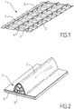
figure 1 est une vue en perspective d'une plaque ondulée d'une cuve selon un mode de réalisation de l'invention, - la
figure 2 est une vue en perspective et en coupe d'une onde de la plaque ondulée de lafigure 1 , et d'un élément de renfort selon une première variante, - les
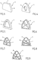
figures 3 à 9 représentent, en perspective, différentes variantes de l'élément de renfort, et - les
figures 10 et 11 représentent, en coupe, d'autres variantes de l'élément de renfort, - la
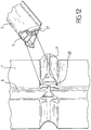
figure 12 montre une vue de dessus de la plaque de lafigure 1 , au niveau d'un croisement d'ondes, ainsi qu'une vue en perspective et en coupe partielle d'un élément de renfort fixé par clipsage sous une onde, - la
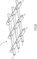
figure 13 représente un élément de renfort destiné à être agencé simultanément sous plusieurs ondes, et - la
figure 14 représente, en perspective éclatée, deux éléments de renfort coopérant entre eux.
- the
figure 1 is a perspective view of a corrugated plate of a tank according to an embodiment of the invention, - the
figure 2 is a perspective view in section of a wave of the corrugated plate of thefigure 1 , and a reinforcing element according to a first variant, - the
Figures 3 to 9 represent, in perspective, different variants of the reinforcing element, and - the
Figures 10 and 11 represent, in section, other variants of the reinforcing element, - the
figure 12 shows a top view of the plaque of thefigure 1 , at a wave crossing, and a perspective view in partial section of a reinforcing element fixed by clipping under a wave, - the
figure 13 represents a reinforcing element intended to be arranged simultaneously under several waves, and - the
figure 14 represents, in exploded perspective, two reinforcing elements cooperating with each other.
Une cuve selon un mode de réalisation de l'invention peut présenter une structure multicouche de manière similaire aux cuves des documents
La plaque 1 représentée sur la
Comme le montre la
En variante, la plaque 1 pourrait présenter un nombre différent de grandes ondes 2 et/ou de petites ondes 3. En variante également, les ondes de la plaque 1 pourraient présenter des nervures de renfort comme décrit dans
Sur la
Dans l'exemple de la
Plusieurs éléments de renfort 5 peuvent être agencés, chacun sous une grande onde 2 entre deux petites ondes 3. Le nombre et la répartition des éléments de renfort 5 peuvent être déterminés en fonction de la répartition des contraintes prévues en fonctionnement dans la membrane de la cuve.Several reinforcing
En variante, la longueur de l'élément de renfort 5 peut être inférieure à la distance entre deux petites ondes 3 ou, si la géométrie du croisement entre ondes le permet, supérieure à cette distance. En variante également, des éléments de renfort 5 peuvent être prévus sous les petites ondes 3.Alternatively, the length of the reinforcing
L'élément de renfort 5 est mis en place comme représenté sur la
De nombreuses formes peuvent convenir pour l'élément de renfort 5. Les
L'élément de renfort 5 de la
L'élément de renfort 5 de la
L'élément de renfort 5 de la
Les éléments de renfort des
Les éléments de renfort 5 des
L'élément de renfort 5 de la
La
La
La
Les différentes formes d'élément de renfort 5 proposées ci-dessus permettent aux ondes de se déformer en cas de contraction thermique, et offrent un support aux ondes en cas de déformation due aux pressions hydrostatique et dynamique. Pour atteindre ce but, on peut prévoir que, lorsque la cuve est vide (donc en l'absence de chargement thermique et de pression hydrostatique ou dynamique), la distance minimale entre l'élément de renfort 5 et l'onde sous laquelle il se trouve soit comprise entre 0 % et 5 % de la hauteur de l'onde.The various forms of reinforcing
Les différentes formes d'élément de renfort 5 présentent chacune des propriétés particulières : coût et facilité de fabrication, résistance mécanique, quantité de matière,... En fonction des applications, on peut choisir la forme la plus appropriée.The different forms of
Des simulations numériques ont été réalisées pour vérifier l'effet de l'élément de renfort 5 sur les contraintes engendrées dans la membrane, par comparaison avec une membrane sans élément de renfort. Ces simulations ont montré que :
- en cas de chargement thermique (contraction de la membrane due au froid), la présence d'un élément de renfort 5 n'introduit pas de contraintes indésirables dans la membrane,
- en cas de chargement thermique et de chargement en pression uniforme (correspondant à la pression hydrostatique de la cargaison), la présence d'un élément de renfort 5 permet de diminuer les contraintes dans la membrane, et
- en cas de chargement thermique et de chargement en pression asymétrique (correspondant à la pression dynamique de la cargaison), la présence d'un élément de renfort 5 permet de diminuer les contraintes dans la membrane.
- in case of thermal loading (contraction of the membrane due to cold), the presence of a reinforcing
element 5 does not introduce undesirable stresses in the membrane, - in the case of thermal loading and uniform pressure loading (corresponding to the hydrostatic pressure of the cargo), the presence of a reinforcing
element 5 makes it possible to reduce the stresses in the membrane, and - in the case of thermal loading and asymmetric pressure loading (corresponding to the dynamic pressure of the cargo), the presence of a reinforcing
element 5 makes it possible to reduce the stresses in the membrane.
Bien que l'invention ait été décrite en liaison avec un mode de réalisation particulier, il est bien évident qu'elle n'y est nullement limitée et qu'elle comprend tous les équivalents techniques des moyens décrits ainsi que leurs combinaisons si celles-ci entrent dans le cadre de l'invention, telle que définie par les revendications.Although the invention has been described in connection with a particular embodiment, it is obvious that it is not limited thereto and that it comprises all the technical equivalents of the means described and their combinations if they are within the scope of the invention as defined by the claims.
Claims (12)
- A fluidtight tank, of which at least one wall comprises a fluidtight membrane intended to be in contact with product contained in the tank, and a plane support adjacent to the membrane, in which tank the membrane comprises at least one corrugated metal sheet (1) made of stainless steel of plane, rectangular overall shape, the corrugated metal sheet having a first series of mutually parallel corrugations (2) and a second series of mutually parallel corrugations (3) which run transverse to the corrugations of the first series and plane portions arranged between the corrugations, wherein the plane portions of the corrugated metal sheet rest on the plane support, characterized in that the fluidtight tank comprises a reinforcing element (5) inserted under a corrugation (2) of the first series between the membrane and the support, in which the reinforcing element has a length that corresponds to the distance between two corrugations of the second series.
- The tank as claimed in claim 1, in which the reinforcing element has an internal passage (9) which allows gas to flow between the corrugation and the support, passing through the reinforcing element.
- The tank as claimed in one of the preceding claims, in which an external passage allows gas to circulate between the corrugation and the support, bypassing the reinforcing element.
- The tank as claimed in one of the preceding claims, in which the reinforcing element is made of a material chosen from: plywood, polyethylene, polycarbonate, glass fiber reinforced polycarbonate, polyether imide and expanded polystyrene.
- The tank as claimed in one of the preceding claims, in which the reinforcing element comprises an outer envelope the shape of which corresponds substantially to the shape of the corrugation.
- The tank as claimed in claim 5, in which the reinforcing element comprises at least one reinforcing web (10) inside said envelope.
- The tank as claimed in one of the preceding claims, in which, when the tank contains no product, the minimum distance between the reinforcing element and the corrugation is comprised between 0% and 5% of the height of the corrugation.
- The tank as claimed in one of the preceding claims, in which the reinforcing element is inserted under the corrugation such that it can slide with respect to the membrane and to the support.
- The tank as claimed in one of claims 1 to 7, in which the reinforcing element is fixed to the membrane or to the support.
- The tank as claimed in claim 9, in which the membrane has an undercut (20), the reinforcing element being clipped to or wedged in the undercut.
- The tank as claimed in one of the preceding claims, in which at least two reinforcing elements are positioned respectively under two adjacent corrugations of the membrane, one of said two reinforcing elements forming an end stop for the other of said two reinforcing elements.
- A floating construction comprising a tank as claimed in one of the preceding claims.
Priority Applications (2)
| Application Number | Priority Date | Filing Date | Title |
|---|---|---|---|
| EP12154056.1A EP2453159B1 (en) | 2008-10-08 | 2009-06-30 | Tank with reinforced corrugated membrane |
| EP12155836.5A EP2455650B1 (en) | 2008-10-08 | 2009-06-30 | Tank with reinforced corrugated membrane |
Applications Claiming Priority (2)
| Application Number | Priority Date | Filing Date | Title |
|---|---|---|---|
| FR0805567A FR2936784B1 (en) | 2008-10-08 | 2008-10-08 | REINFORCED CORRUGATED MEMBRANE TANK |
| PCT/FR2009/051267 WO2010040922A1 (en) | 2008-10-08 | 2009-06-30 | Vessel with a reinforced corrugated membrane |
Related Child Applications (4)
| Application Number | Title | Priority Date | Filing Date |
|---|---|---|---|
| EP12155836.5A Division EP2455650B1 (en) | 2008-10-08 | 2009-06-30 | Tank with reinforced corrugated membrane |
| EP12155836.5A Division-Into EP2455650B1 (en) | 2008-10-08 | 2009-06-30 | Tank with reinforced corrugated membrane |
| EP12154056.1A Division EP2453159B1 (en) | 2008-10-08 | 2009-06-30 | Tank with reinforced corrugated membrane |
| EP12154056.1A Division-Into EP2453159B1 (en) | 2008-10-08 | 2009-06-30 | Tank with reinforced corrugated membrane |
Publications (2)
| Publication Number | Publication Date |
|---|---|
| EP2337984A1 EP2337984A1 (en) | 2011-06-29 |
| EP2337984B1 true EP2337984B1 (en) | 2019-11-27 |
Family
ID=40586195
Family Applications (3)
| Application Number | Title | Priority Date | Filing Date |
|---|---|---|---|
| EP12155836.5A Active EP2455650B1 (en) | 2008-10-08 | 2009-06-30 | Tank with reinforced corrugated membrane |
| EP12154056.1A Active EP2453159B1 (en) | 2008-10-08 | 2009-06-30 | Tank with reinforced corrugated membrane |
| EP09784452.6A Active EP2337984B1 (en) | 2008-10-08 | 2009-06-30 | Vessel with a reinforced corrugated membrane |
Family Applications Before (2)
| Application Number | Title | Priority Date | Filing Date |
|---|---|---|---|
| EP12155836.5A Active EP2455650B1 (en) | 2008-10-08 | 2009-06-30 | Tank with reinforced corrugated membrane |
| EP12154056.1A Active EP2453159B1 (en) | 2008-10-08 | 2009-06-30 | Tank with reinforced corrugated membrane |
Country Status (12)
| Country | Link |
|---|---|
| EP (3) | EP2455650B1 (en) |
| JP (3) | JP5379234B2 (en) |
| KR (7) | KR20220003163A (en) |
| CN (3) | CN102588733B (en) |
| AU (1) | AU2009301016B2 (en) |
| BR (1) | BRPI0920667B1 (en) |
| ES (2) | ES2821391T3 (en) |
| FR (1) | FR2936784B1 (en) |
| MX (1) | MX2011003688A (en) |
| MY (2) | MY154077A (en) |
| RU (3) | RU2535293C2 (en) |
| WO (1) | WO2010040922A1 (en) |
Families Citing this family (29)
| Publication number | Priority date | Publication date | Assignee | Title |
|---|---|---|---|---|
| CN101959752B (en) * | 2008-03-03 | 2014-03-26 | 三星重工业株式会社 | Reinforcement member for membrane of liquefied natural gas cargo, membrane assembly having same, and construction method for same |
| FR2936784B1 (en) * | 2008-10-08 | 2010-10-08 | Gaztransp Et Technigaz | REINFORCED CORRUGATED MEMBRANE TANK |
| FR2963818B1 (en) * | 2010-08-11 | 2014-01-03 | Gaztransp Et Technigaz | SEALED WALL STRUCTURE |
| KR101236746B1 (en) | 2010-11-17 | 2013-02-25 | 삼성중공업 주식회사 | membrane reinforcement of LNG ship |
| KR101337639B1 (en) * | 2011-12-13 | 2013-12-05 | 삼성중공업 주식회사 | Combination structure of reinforcing member for primary barrier of lng storage tank |
| KR101337642B1 (en) * | 2011-12-16 | 2013-12-05 | 삼성중공업 주식회사 | Liquefied Natural Gas storage tank and method to manufacture the same |
| KR101349875B1 (en) * | 2011-12-16 | 2014-01-16 | 주식회사 티엠씨 | Fixing structure of reinforcing member for primary barrier of lng storage tank |
| KR101349881B1 (en) * | 2012-06-13 | 2014-01-16 | 삼성중공업 주식회사 | Device for fixing the primary barrier reinforcement member of lng storage tank |
| FR2998256B1 (en) | 2012-11-16 | 2019-12-20 | Gaztransport Et Technigaz | PROCESS FOR THE MANUFACTURE OF A WATERPROOF AND THERMALLY INSULATED TANK WALL |
| FR3009745B1 (en) * | 2013-08-15 | 2016-01-29 | Gaztransp Et Technigaz | SEALED AND THERMALLY INSULATING TANK WITH ANGLE PIECE |
| CN104209080B (en) * | 2014-09-09 | 2016-08-24 | 清华大学 | Tongue tray ripple packing |
| CN105561880B (en) * | 2014-10-13 | 2018-08-10 | 彭碳科技有限公司 | A kind of container containing energy of composite construction |
| FR3039248B1 (en) * | 2015-07-24 | 2017-08-18 | Gaztransport Et Technigaz | WATERPROOF AND THERMALLY INSULATING TANK WITH A REINFORCING PIECE |
| FR3050008B1 (en) * | 2016-04-11 | 2018-04-27 | Gaztransport Et Technigaz | WATERPROOF TANK WITH CORRUGATED SEALING MEMBRANES |
| KR102490347B1 (en) * | 2016-10-24 | 2023-01-20 | 대우조선해양 주식회사 | Reinforcing member for corrugated membrane and lng storage tank having the reinforcing member |
| FR3061046B1 (en) | 2016-12-23 | 2019-05-24 | Gaztransport Et Technigaz | FOLDING DEVICE FOR FORMING A CORRUGATION IN A METAL SHEET AND METHOD OF USING THE SAME |
| JP6766948B2 (en) * | 2017-03-22 | 2020-10-14 | 株式会社Ihi | Low temperature tank and its manufacturing method |
| FR3074253B1 (en) * | 2017-11-27 | 2019-11-01 | Gaztransport Et Technigaz | SEALED AND THERMALLY INSULATED TANK |
| FR3077278B1 (en) * | 2018-02-01 | 2020-02-07 | Gaztransport Et Technigaz | WATERPROOF WALL WITH REINFORCED CORRUGATED MEMBRANE |
| FR3083789B1 (en) * | 2018-07-13 | 2020-07-10 | Gaztransport Et Technigaz | TANK WALL COMPRISING A SEALING MEMBRANE HAVING A CORRUGATION HAVING A REINFORCED CURVILINE PORTION |
| FR3084438B1 (en) * | 2018-07-26 | 2020-07-31 | Gaztransport Et Technigaz | WATERPROOF AND THERMALLY INSULATED TANK |
| FR3084346B1 (en) * | 2018-07-27 | 2020-12-25 | Gaztransport Et Technigaz | WATERPROOF WALL WITH REINFORCED CORRUGATED MEMBRANE |
| FR3087871B1 (en) * | 2018-10-31 | 2022-09-09 | Gaztransport Et Technigaz | SECURING CONNECTION PARTS ON THE EDGE OF A PLATE CONSTITUTIVE OF A SEALED TANK WITH CORRUGATED MEMBRANES |
| FR3094338B1 (en) * | 2019-03-26 | 2021-09-10 | Gaztransport Et Technigaz | Device for maintaining wave reinforcements when installing a tank wall. |
| CN112124523B (en) * | 2020-04-21 | 2022-10-14 | 沪东中华造船(集团)有限公司 | Installation method for film reinforcing wedge of Mark3 type liquid cargo tank |
| CN112145954B (en) * | 2020-09-21 | 2022-04-26 | 浙江振申绝热科技股份有限公司 | Tank bottom structure of metal inner tank of membrane type low-temperature storage tank |
| FR3133900A1 (en) | 2022-03-28 | 2023-09-29 | Gaztransport Et Technigaz | Waterproof and thermally insulating tank |
| FR3135773A1 (en) | 2022-05-23 | 2023-11-24 | Gaztransport Et Technigaz | WATERPROOF AND THERMALLY INSULATING TANK INTEGRATED INTO A SUPPORT STRUCTURE |
| CN115817725A (en) * | 2022-12-12 | 2023-03-21 | 中太海事技术(上海)有限公司 | Arrangement form of corrugated membrane |
Family Cites Families (34)
| Publication number | Priority date | Publication date | Assignee | Title |
|---|---|---|---|---|
| US3341051A (en) * | 1964-12-24 | 1967-09-12 | Exxon Research Engineering Co | Cryogenic insulation system |
| JPS43290Y1 (en) * | 1966-05-30 | 1968-01-09 | ||
| SU820673A3 (en) * | 1974-01-24 | 1981-04-07 | Текнигаз С.А. (Фирма) | Thermoinsulating tank wall |
| JPS53160816U (en) * | 1977-05-24 | 1978-12-16 | ||
| JPS5452317A (en) * | 1977-10-04 | 1979-04-24 | Ishikawajima Harima Heavy Ind Co Ltd | Double shell roof membrane type low temperture underground tank |
| JPS5559024U (en) * | 1978-10-17 | 1980-04-22 | ||
| JPS5578896A (en) * | 1978-12-12 | 1980-06-13 | Kawasaki Heavy Ind Ltd | Membrane structure of low temperature tank |
| JPS55122600U (en) * | 1979-02-23 | 1980-08-30 | ||
| JPS55122600A (en) * | 1979-03-15 | 1980-09-20 | Matsushita Electric Ind Co Ltd | Steam iron |
| JPS56109993A (en) * | 1980-02-05 | 1981-08-31 | Ishikawajima Harima Heavy Ind Co Ltd | Expansion joint used in fluid storing tank at corner part of its side wall |
| JPS5710598U (en) * | 1980-06-20 | 1982-01-20 | ||
| JPS57165900U (en) * | 1981-04-14 | 1982-10-19 | ||
| JPS6098296A (en) * | 1983-10-31 | 1985-06-01 | Mitsubishi Heavy Ind Ltd | Low-temperature corrugated expansion joint |
| JPS6098298A (en) * | 1983-11-02 | 1985-06-01 | Mitsubishi Heavy Ind Ltd | Bent membrane corrugation |
| JPH02109885A (en) * | 1988-10-14 | 1990-04-23 | Nkk Corp | Container equipped with jacket |
| SU1610189A1 (en) * | 1988-12-13 | 1990-11-30 | Институт Электросварки Им.Е.О.Патона | Gas cylinder |
| FR2669396B1 (en) * | 1990-11-19 | 1997-05-09 | Inst Francais Du Petrole | LOW UNIT WEIGHT TANK, ESPECIALLY FOR THE STORAGE OF PRESSURIZED FLUIDS AND ITS MANUFACTURING METHOD. |
| FR2706578B1 (en) * | 1993-06-18 | 1995-09-01 | Inst Francais Du Petrole | Pressure oil storage tank. |
| FR2735847B1 (en) * | 1995-06-22 | 1997-08-14 | Korea Gas Corp | MEMBRANE FOR LIQUEFIED NATURAL GAS STORAGE TANK |
| EP0855212B1 (en) * | 1995-09-21 | 2006-11-15 | Asahi Kasei Kabushiki Kaisha | Hollow fiber membrane module |
| DZ2535A1 (en) * | 1997-06-20 | 2003-01-08 | Exxon Production Research Co | Advanced process for liquefying natural gas. |
| FR2781557B1 (en) * | 1998-07-24 | 2000-09-15 | Gaz Transport & Technigaz | IMPROVEMENT FOR A WATERPROOF AND THERMALLY INSULATING TANK WITH PREFABRICATED PANELS |
| US6547092B1 (en) * | 2000-11-14 | 2003-04-15 | Solomon Chervatsky | Pressure vessel with thin unstressed metallic liner |
| JP2002181288A (en) * | 2000-12-14 | 2002-06-26 | Ishikawajima Harima Heavy Ind Co Ltd | Low-temperature liquefied gas membrane tank |
| FR2861060B1 (en) * | 2003-10-16 | 2006-01-06 | Gaz Transport & Technigaz | WATERPROOF STRUCTURE AND TANK PROVIDED WITH SUCH A STRUCTURE |
| KR100706509B1 (en) * | 2003-11-25 | 2007-04-11 | 현대중공업 주식회사 | Membrance metal panel of insulated cargo thaks of LNG carrier |
| KR100750487B1 (en) * | 2004-02-02 | 2007-08-22 | 현대중공업 주식회사 | Membrane metal panel with flat welding joint part for insulated cargo tanks of LNG carrier |
| US7456493B2 (en) * | 2005-04-15 | 2008-11-25 | Alps Electric Co., Ltd. | Structure for mounting semiconductor part in which bump and land portion are hardly detached from each other and method of manufacturing mounting substrate used therein |
| WO2008007837A1 (en) * | 2006-07-11 | 2008-01-17 | Hyundai Heavy Industries Co., Ltd. | Seam butt type insulation system having weldable secondary barrier for lng tanks |
| CN101959752B (en) * | 2008-03-03 | 2014-03-26 | 三星重工业株式会社 | Reinforcement member for membrane of liquefied natural gas cargo, membrane assembly having same, and construction method for same |
| EP2310016B1 (en) | 2008-08-05 | 2017-10-04 | Omeros Corporation | Pde10 inhibitors and related compositions and methods |
| FR2936784B1 (en) * | 2008-10-08 | 2010-10-08 | Gaztransp Et Technigaz | REINFORCED CORRUGATED MEMBRANE TANK |
| JP2012066540A (en) | 2010-09-27 | 2012-04-05 | Panasonic Corp | Gas barrier film |
| JP2012066539A (en) | 2010-09-27 | 2012-04-05 | Toppan Printing Co Ltd | Metal mask and solder paste printing method using the metal mask |
-
2008
- 2008-10-08 FR FR0805567A patent/FR2936784B1/en not_active Expired - Fee Related
-
2009
- 2009-06-30 ES ES12154056T patent/ES2821391T3/en active Active
- 2009-06-30 KR KR1020217043168A patent/KR20220003163A/en not_active Application Discontinuation
- 2009-06-30 EP EP12155836.5A patent/EP2455650B1/en active Active
- 2009-06-30 KR KR1020147007291A patent/KR20140042936A/en active Search and Examination
- 2009-06-30 RU RU2012105125/06A patent/RU2535293C2/en active
- 2009-06-30 BR BRPI0920667-1A patent/BRPI0920667B1/en not_active IP Right Cessation
- 2009-06-30 KR KR1020117010310A patent/KR20110070998A/en active Application Filing
- 2009-06-30 CN CN201210056610.4A patent/CN102588733B/en active Active
- 2009-06-30 WO PCT/FR2009/051267 patent/WO2010040922A1/en active Application Filing
- 2009-06-30 CN CN201210056536.6A patent/CN102588732B/en active Active
- 2009-06-30 EP EP12154056.1A patent/EP2453159B1/en active Active
- 2009-06-30 RU RU2011116959/06A patent/RU2505737C2/en active
- 2009-06-30 AU AU2009301016A patent/AU2009301016B2/en active Active
- 2009-06-30 KR KR1020127006125A patent/KR20120031313A/en active Search and Examination
- 2009-06-30 KR KR1020167004287A patent/KR101645155B1/en active IP Right Grant
- 2009-06-30 JP JP2011530521A patent/JP5379234B2/en active Active
- 2009-06-30 MX MX2011003688A patent/MX2011003688A/en active IP Right Grant
- 2009-06-30 CN CN2009801398437A patent/CN102177389A/en active Pending
- 2009-06-30 MY MYPI2011001568A patent/MY154077A/en unknown
- 2009-06-30 ES ES09784452T patent/ES2767975T3/en active Active
- 2009-06-30 KR KR1020177026964A patent/KR102594126B1/en active IP Right Grant
- 2009-06-30 KR KR1020127006124A patent/KR20120031312A/en active Search and Examination
- 2009-06-30 EP EP09784452.6A patent/EP2337984B1/en active Active
- 2009-06-30 RU RU2012107912/06A patent/RU2533271C2/en active
- 2009-06-30 MY MYPI2014002054A patent/MY174853A/en unknown
-
2012
- 2012-03-23 JP JP2012066539A patent/JP5778606B2/en active Active
- 2012-03-23 JP JP2012066540A patent/JP5379258B2/en active Active
Non-Patent Citations (1)
| Title |
|---|
| None * |
Also Published As
Similar Documents
| Publication | Publication Date | Title |
|---|---|---|
| EP2337984B1 (en) | Vessel with a reinforced corrugated membrane | |
| EP3198186B1 (en) | Sealed and insulating vessel comprising a bridging element between the panels of the secondary insulation barrier | |
| FR3001945A1 (en) | WATERPROOF AND THERMALLY INSULATING WALL FOR FLUID STORAGE TANK | |
| EP3004719B1 (en) | Method for manufacturing a freestanding body for thermal insulation of a vessel for storing a fluid and freestanding body produced thereby | |
| FR3077278A1 (en) | WATERPROOFING WALL WITH REINFORCED CORRUGATED MEMBRANE | |
| WO2012020194A1 (en) | Impervious wall structure | |
| EP3365592B1 (en) | Vessel including insulating corner blocks provided with stress relief slots | |
| EP3004718B1 (en) | Self-supporting case for thermally insulating a fluid storage tank and method for producing such a case | |
| FR3084347A1 (en) | WATERPROOF WALL WITH REINFORCED CORRUGATED MEMBRANE | |
| EP3596383B1 (en) | Thermally insulating sealed tank comprising a reinforcing insulating plug | |
| FR3052229A1 (en) | SEALED AND THERMALLY INSULATING TANK INTEGRATED IN A POLYEDRIAL CARRIER STRUCTURE | |
| FR3014085A1 (en) | SELF-CONDUCTING BODY FOR THE THERMAL INSULATION OF A STORAGE TANK FOR A FLUID | |
| FR3102228A1 (en) | Sealed and thermally insulating tank | |
| EP3055606B1 (en) | Self-supporting box for thermally insulating a fluid storage tank and method for producing such a box | |
| FR3084346A1 (en) | WATERPROOF WALL WITH REINFORCED CORRUGATED MEMBRANE | |
| FR3083789A1 (en) | TANK WALL COMPRISING A SEALING MEMBRANE HAVING A CORRUGATION HAVING A REINFORCED CURVILINE PORTION | |
| WO2022090341A1 (en) | Sealed and thermally insulating tank | |
| WO2022013031A1 (en) | Sealed and thermally insulating tank | |
| FR3115853A1 (en) | Watertight and thermally insulated tank | |
| WO2020193653A1 (en) | Storage facility for liquefied gas | |
| FR3112587A1 (en) | Watertight and thermally insulated tank | |
| FR3118118A1 (en) | Sealed and thermally insulating tank comprising a bridging element | |
| FR3094453A1 (en) | Storage facility for liquefied gas | |
| FR3077513A1 (en) | PILLAR SPACE | |
| FR3115093A1 (en) | Watertight and thermally insulated tank |
Legal Events
| Date | Code | Title | Description |
|---|---|---|---|
| PUAI | Public reference made under article 153(3) epc to a published international application that has entered the european phase |
Free format text: ORIGINAL CODE: 0009012 |
|
| 17P | Request for examination filed |
Effective date: 20110317 |
|
| AK | Designated contracting states |
Kind code of ref document: A1 Designated state(s): AT BE BG CH CY CZ DE DK EE ES FI FR GB GR HR HU IE IS IT LI LT LU LV MC MK MT NL NO PL PT RO SE SI SK TR |
|
| AX | Request for extension of the european patent |
Extension state: AL BA RS |
|
| DAX | Request for extension of the european patent (deleted) | ||
| TPAC | Observations filed by third parties |
Free format text: ORIGINAL CODE: EPIDOSNTIPA |
|
| 17Q | First examination report despatched |
Effective date: 20121113 |
|
| TPAC | Observations filed by third parties |
Free format text: ORIGINAL CODE: EPIDOSNTIPA |
|
| TPAC | Observations filed by third parties |
Free format text: ORIGINAL CODE: EPIDOSNTIPA |
|
| RAP1 | Party data changed (applicant data changed or rights of an application transferred) |
Owner name: GAZTRANSPORT ET TECHNIGAZ S.A. |
|
| STAA | Information on the status of an ep patent application or granted ep patent |
Free format text: STATUS: EXAMINATION IS IN PROGRESS |
|
| RAP1 | Party data changed (applicant data changed or rights of an application transferred) |
Owner name: GAZTRANSPORT ET TECHNIGAZ |
|
| GRAP | Despatch of communication of intention to grant a patent |
Free format text: ORIGINAL CODE: EPIDOSNIGR1 |
|
| STAA | Information on the status of an ep patent application or granted ep patent |
Free format text: STATUS: GRANT OF PATENT IS INTENDED |
|
| INTG | Intention to grant announced |
Effective date: 20190319 |
|
| GRAJ | Information related to disapproval of communication of intention to grant by the applicant or resumption of examination proceedings by the epo deleted |
Free format text: ORIGINAL CODE: EPIDOSDIGR1 |
|
| STAA | Information on the status of an ep patent application or granted ep patent |
Free format text: STATUS: EXAMINATION IS IN PROGRESS |
|
| INTC | Intention to grant announced (deleted) | ||
| GRAS | Grant fee paid |
Free format text: ORIGINAL CODE: EPIDOSNIGR3 |
|
| STAA | Information on the status of an ep patent application or granted ep patent |
Free format text: STATUS: GRANT OF PATENT IS INTENDED |
|
| GRAP | Despatch of communication of intention to grant a patent |
Free format text: ORIGINAL CODE: EPIDOSNIGR1 |
|
| GRAA | (expected) grant |
Free format text: ORIGINAL CODE: 0009210 |
|
| STAA | Information on the status of an ep patent application or granted ep patent |
Free format text: STATUS: THE PATENT HAS BEEN GRANTED |
|
| INTG | Intention to grant announced |
Effective date: 20190930 |
|
| RIN1 | Information on inventor provided before grant (corrected) |
Inventor name: CANLER, GERY Inventor name: DELETRE, BRUNO Inventor name: YATAGHENE, MOKRANE |
|
| AK | Designated contracting states |
Kind code of ref document: B1 Designated state(s): AT BE BG CH CY CZ DE DK EE ES FI FR GB GR HR HU IE IS IT LI LT LU LV MC MK MT NL NO PL PT RO SE SI SK TR |
|
| REG | Reference to a national code |
Ref country code: GB Ref legal event code: FG4D Free format text: NOT ENGLISH |
|
| REG | Reference to a national code |
Ref country code: CH Ref legal event code: EP |
|
| REG | Reference to a national code |
Ref country code: AT Ref legal event code: REF Ref document number: 1207068 Country of ref document: AT Kind code of ref document: T Effective date: 20191215 |
|
| REG | Reference to a national code |
Ref country code: DE Ref legal event code: R096 Ref document number: 602009060565 Country of ref document: DE |
|
| REG | Reference to a national code |
Ref country code: IE Ref legal event code: FG4D Free format text: LANGUAGE OF EP DOCUMENT: FRENCH |
|
| REG | Reference to a national code |
Ref country code: NO Ref legal event code: T2 Effective date: 20191127 |
|
| REG | Reference to a national code |
Ref country code: NL Ref legal event code: FP |
|
| REG | Reference to a national code |
Ref country code: LT Ref legal event code: MG4D |
|
| PG25 | Lapsed in a contracting state [announced via postgrant information from national office to epo] |
Ref country code: FI Free format text: LAPSE BECAUSE OF FAILURE TO SUBMIT A TRANSLATION OF THE DESCRIPTION OR TO PAY THE FEE WITHIN THE PRESCRIBED TIME-LIMIT Effective date: 20191127 Ref country code: LV Free format text: LAPSE BECAUSE OF FAILURE TO SUBMIT A TRANSLATION OF THE DESCRIPTION OR TO PAY THE FEE WITHIN THE PRESCRIBED TIME-LIMIT Effective date: 20191127 Ref country code: SE Free format text: LAPSE BECAUSE OF FAILURE TO SUBMIT A TRANSLATION OF THE DESCRIPTION OR TO PAY THE FEE WITHIN THE PRESCRIBED TIME-LIMIT Effective date: 20191127 Ref country code: BG Free format text: LAPSE BECAUSE OF FAILURE TO SUBMIT A TRANSLATION OF THE DESCRIPTION OR TO PAY THE FEE WITHIN THE PRESCRIBED TIME-LIMIT Effective date: 20200227 Ref country code: LT Free format text: LAPSE BECAUSE OF FAILURE TO SUBMIT A TRANSLATION OF THE DESCRIPTION OR TO PAY THE FEE WITHIN THE PRESCRIBED TIME-LIMIT Effective date: 20191127 Ref country code: GR Free format text: LAPSE BECAUSE OF FAILURE TO SUBMIT A TRANSLATION OF THE DESCRIPTION OR TO PAY THE FEE WITHIN THE PRESCRIBED TIME-LIMIT Effective date: 20200228 |
|
| PG25 | Lapsed in a contracting state [announced via postgrant information from national office to epo] |
Ref country code: HR Free format text: LAPSE BECAUSE OF FAILURE TO SUBMIT A TRANSLATION OF THE DESCRIPTION OR TO PAY THE FEE WITHIN THE PRESCRIBED TIME-LIMIT Effective date: 20191127 Ref country code: IS Free format text: LAPSE BECAUSE OF FAILURE TO SUBMIT A TRANSLATION OF THE DESCRIPTION OR TO PAY THE FEE WITHIN THE PRESCRIBED TIME-LIMIT Effective date: 20200327 |
|
| REG | Reference to a national code |
Ref country code: ES Ref legal event code: FG2A Ref document number: 2767975 Country of ref document: ES Kind code of ref document: T3 Effective date: 20200619 |
|
| PG25 | Lapsed in a contracting state [announced via postgrant information from national office to epo] |
Ref country code: EE Free format text: LAPSE BECAUSE OF FAILURE TO SUBMIT A TRANSLATION OF THE DESCRIPTION OR TO PAY THE FEE WITHIN THE PRESCRIBED TIME-LIMIT Effective date: 20191127 Ref country code: PT Free format text: LAPSE BECAUSE OF FAILURE TO SUBMIT A TRANSLATION OF THE DESCRIPTION OR TO PAY THE FEE WITHIN THE PRESCRIBED TIME-LIMIT Effective date: 20200419 Ref country code: DK Free format text: LAPSE BECAUSE OF FAILURE TO SUBMIT A TRANSLATION OF THE DESCRIPTION OR TO PAY THE FEE WITHIN THE PRESCRIBED TIME-LIMIT Effective date: 20191127 Ref country code: RO Free format text: LAPSE BECAUSE OF FAILURE TO SUBMIT A TRANSLATION OF THE DESCRIPTION OR TO PAY THE FEE WITHIN THE PRESCRIBED TIME-LIMIT Effective date: 20191127 Ref country code: CZ Free format text: LAPSE BECAUSE OF FAILURE TO SUBMIT A TRANSLATION OF THE DESCRIPTION OR TO PAY THE FEE WITHIN THE PRESCRIBED TIME-LIMIT Effective date: 20191127 |
|
| REG | Reference to a national code |
Ref country code: DE Ref legal event code: R097 Ref document number: 602009060565 Country of ref document: DE |
|
| PG25 | Lapsed in a contracting state [announced via postgrant information from national office to epo] |
Ref country code: SK Free format text: LAPSE BECAUSE OF FAILURE TO SUBMIT A TRANSLATION OF THE DESCRIPTION OR TO PAY THE FEE WITHIN THE PRESCRIBED TIME-LIMIT Effective date: 20191127 |
|
| REG | Reference to a national code |
Ref country code: AT Ref legal event code: MK05 Ref document number: 1207068 Country of ref document: AT Kind code of ref document: T Effective date: 20191127 |
|
| PLBE | No opposition filed within time limit |
Free format text: ORIGINAL CODE: 0009261 |
|
| STAA | Information on the status of an ep patent application or granted ep patent |
Free format text: STATUS: NO OPPOSITION FILED WITHIN TIME LIMIT |
|
| 26N | No opposition filed |
Effective date: 20200828 |
|
| PG25 | Lapsed in a contracting state [announced via postgrant information from national office to epo] |
Ref country code: AT Free format text: LAPSE BECAUSE OF FAILURE TO SUBMIT A TRANSLATION OF THE DESCRIPTION OR TO PAY THE FEE WITHIN THE PRESCRIBED TIME-LIMIT Effective date: 20191127 Ref country code: SI Free format text: LAPSE BECAUSE OF FAILURE TO SUBMIT A TRANSLATION OF THE DESCRIPTION OR TO PAY THE FEE WITHIN THE PRESCRIBED TIME-LIMIT Effective date: 20191127 Ref country code: PL Free format text: LAPSE BECAUSE OF FAILURE TO SUBMIT A TRANSLATION OF THE DESCRIPTION OR TO PAY THE FEE WITHIN THE PRESCRIBED TIME-LIMIT Effective date: 20191127 |
|
| REG | Reference to a national code |
Ref country code: DE Ref legal event code: R119 Ref document number: 602009060565 Country of ref document: DE |
|
| PG25 | Lapsed in a contracting state [announced via postgrant information from national office to epo] |
Ref country code: IT Free format text: LAPSE BECAUSE OF FAILURE TO SUBMIT A TRANSLATION OF THE DESCRIPTION OR TO PAY THE FEE WITHIN THE PRESCRIBED TIME-LIMIT Effective date: 20191127 Ref country code: MC Free format text: LAPSE BECAUSE OF FAILURE TO SUBMIT A TRANSLATION OF THE DESCRIPTION OR TO PAY THE FEE WITHIN THE PRESCRIBED TIME-LIMIT Effective date: 20191127 |
|
| REG | Reference to a national code |
Ref country code: CH Ref legal event code: PL |
|
| PG25 | Lapsed in a contracting state [announced via postgrant information from national office to epo] |
Ref country code: LU Free format text: LAPSE BECAUSE OF NON-PAYMENT OF DUE FEES Effective date: 20200630 |
|
| REG | Reference to a national code |
Ref country code: BE Ref legal event code: MM Effective date: 20200630 |
|
| PG25 | Lapsed in a contracting state [announced via postgrant information from national office to epo] |
Ref country code: IE Free format text: LAPSE BECAUSE OF NON-PAYMENT OF DUE FEES Effective date: 20200630 Ref country code: LI Free format text: LAPSE BECAUSE OF NON-PAYMENT OF DUE FEES Effective date: 20200630 Ref country code: CH Free format text: LAPSE BECAUSE OF NON-PAYMENT OF DUE FEES Effective date: 20200630 |
|
| PG25 | Lapsed in a contracting state [announced via postgrant information from national office to epo] |
Ref country code: DE Free format text: LAPSE BECAUSE OF NON-PAYMENT OF DUE FEES Effective date: 20210101 Ref country code: BE Free format text: LAPSE BECAUSE OF NON-PAYMENT OF DUE FEES Effective date: 20200630 |
|
| PG25 | Lapsed in a contracting state [announced via postgrant information from national office to epo] |
Ref country code: TR Free format text: LAPSE BECAUSE OF FAILURE TO SUBMIT A TRANSLATION OF THE DESCRIPTION OR TO PAY THE FEE WITHIN THE PRESCRIBED TIME-LIMIT Effective date: 20191127 Ref country code: MT Free format text: LAPSE BECAUSE OF FAILURE TO SUBMIT A TRANSLATION OF THE DESCRIPTION OR TO PAY THE FEE WITHIN THE PRESCRIBED TIME-LIMIT Effective date: 20191127 Ref country code: CY Free format text: LAPSE BECAUSE OF FAILURE TO SUBMIT A TRANSLATION OF THE DESCRIPTION OR TO PAY THE FEE WITHIN THE PRESCRIBED TIME-LIMIT Effective date: 20191127 |
|
| PG25 | Lapsed in a contracting state [announced via postgrant information from national office to epo] |
Ref country code: MK Free format text: LAPSE BECAUSE OF FAILURE TO SUBMIT A TRANSLATION OF THE DESCRIPTION OR TO PAY THE FEE WITHIN THE PRESCRIBED TIME-LIMIT Effective date: 20191127 |
|
| P01 | Opt-out of the competence of the unified patent court (upc) registered |
Effective date: 20230614 |
|
| PGFP | Annual fee paid to national office [announced via postgrant information from national office to epo] |
Ref country code: NO Payment date: 20230524 Year of fee payment: 15 Ref country code: NL Payment date: 20230525 Year of fee payment: 15 Ref country code: FR Payment date: 20230622 Year of fee payment: 15 |
|
| PGFP | Annual fee paid to national office [announced via postgrant information from national office to epo] |
Ref country code: GB Payment date: 20230620 Year of fee payment: 15 Ref country code: ES Payment date: 20230706 Year of fee payment: 15 |