EP2334522B1 - Airbag module for a motor vehicle - Google Patents
Airbag module for a motor vehicle Download PDFInfo
- Publication number
- EP2334522B1 EP2334522B1 EP09743882A EP09743882A EP2334522B1 EP 2334522 B1 EP2334522 B1 EP 2334522B1 EP 09743882 A EP09743882 A EP 09743882A EP 09743882 A EP09743882 A EP 09743882A EP 2334522 B1 EP2334522 B1 EP 2334522B1
- Authority
- EP
- European Patent Office
- Prior art keywords
- airbag module
- generating device
- movable element
- movement generating
- airbag
- Prior art date
- Legal status (The legal status is an assumption and is not a legal conclusion. Google has not performed a legal analysis and makes no representation as to the accuracy of the status listed.)
- Not-in-force
Links
Images


Classifications
-
- B—PERFORMING OPERATIONS; TRANSPORTING
- B60—VEHICLES IN GENERAL
- B60R—VEHICLES, VEHICLE FITTINGS, OR VEHICLE PARTS, NOT OTHERWISE PROVIDED FOR
- B60R21/00—Arrangements or fittings on vehicles for protecting or preventing injuries to occupants or pedestrians in case of accidents or other traffic risks
- B60R21/02—Occupant safety arrangements or fittings, e.g. crash pads
- B60R21/16—Inflatable occupant restraints or confinements designed to inflate upon impact or impending impact, e.g. air bags
- B60R21/23—Inflatable members
- B60R21/239—Inflatable members characterised by their venting means
-
- B—PERFORMING OPERATIONS; TRANSPORTING
- B60—VEHICLES IN GENERAL
- B60R—VEHICLES, VEHICLE FITTINGS, OR VEHICLE PARTS, NOT OTHERWISE PROVIDED FOR
- B60R21/00—Arrangements or fittings on vehicles for protecting or preventing injuries to occupants or pedestrians in case of accidents or other traffic risks
- B60R21/02—Occupant safety arrangements or fittings, e.g. crash pads
- B60R21/16—Inflatable occupant restraints or confinements designed to inflate upon impact or impending impact, e.g. air bags
- B60R21/20—Arrangements for storing inflatable members in their non-use or deflated condition; Arrangement or mounting of air bag modules or components
- B60R21/201—Packaging straps or envelopes for inflatable members
-
- B—PERFORMING OPERATIONS; TRANSPORTING
- B60—VEHICLES IN GENERAL
- B60R—VEHICLES, VEHICLE FITTINGS, OR VEHICLE PARTS, NOT OTHERWISE PROVIDED FOR
- B60R21/00—Arrangements or fittings on vehicles for protecting or preventing injuries to occupants or pedestrians in case of accidents or other traffic risks
- B60R21/02—Occupant safety arrangements or fittings, e.g. crash pads
- B60R21/16—Inflatable occupant restraints or confinements designed to inflate upon impact or impending impact, e.g. air bags
- B60R21/23—Inflatable members
- B60R21/231—Inflatable members characterised by their shape, construction or spatial configuration
- B60R21/2334—Expansion control features
- B60R21/2338—Tethers
- B60R2021/23382—Internal tether means
- B60R2021/23384—Internal tether means having ends which are movable or detachable during deployment
-
- B—PERFORMING OPERATIONS; TRANSPORTING
- B60—VEHICLES IN GENERAL
- B60R—VEHICLES, VEHICLE FITTINGS, OR VEHICLE PARTS, NOT OTHERWISE PROVIDED FOR
- B60R21/00—Arrangements or fittings on vehicles for protecting or preventing injuries to occupants or pedestrians in case of accidents or other traffic risks
- B60R21/02—Occupant safety arrangements or fittings, e.g. crash pads
- B60R21/16—Inflatable occupant restraints or confinements designed to inflate upon impact or impending impact, e.g. air bags
- B60R21/23—Inflatable members
- B60R21/239—Inflatable members characterised by their venting means
- B60R2021/2395—Inflatable members characterised by their venting means comprising means to control the venting
-
- B—PERFORMING OPERATIONS; TRANSPORTING
- B60—VEHICLES IN GENERAL
- B60R—VEHICLES, VEHICLE FITTINGS, OR VEHICLE PARTS, NOT OTHERWISE PROVIDED FOR
- B60R21/00—Arrangements or fittings on vehicles for protecting or preventing injuries to occupants or pedestrians in case of accidents or other traffic risks
- B60R21/02—Occupant safety arrangements or fittings, e.g. crash pads
- B60R21/16—Inflatable occupant restraints or confinements designed to inflate upon impact or impending impact, e.g. air bags
- B60R21/26—Inflatable occupant restraints or confinements designed to inflate upon impact or impending impact, e.g. air bags characterised by the inflation fluid source or means to control inflation fluid flow
- B60R2021/26017—Inflatable occupant restraints or confinements designed to inflate upon impact or impending impact, e.g. air bags characterised by the inflation fluid source or means to control inflation fluid flow a cooling agent being added to the inflation fluid
-
- Y—GENERAL TAGGING OF NEW TECHNOLOGICAL DEVELOPMENTS; GENERAL TAGGING OF CROSS-SECTIONAL TECHNOLOGIES SPANNING OVER SEVERAL SECTIONS OF THE IPC; TECHNICAL SUBJECTS COVERED BY FORMER USPC CROSS-REFERENCE ART COLLECTIONS [XRACs] AND DIGESTS
- Y10—TECHNICAL SUBJECTS COVERED BY FORMER USPC
- Y10S—TECHNICAL SUBJECTS COVERED BY FORMER USPC CROSS-REFERENCE ART COLLECTIONS [XRACs] AND DIGESTS
- Y10S102/00—Ammunition and explosives
- Y10S102/704—Coolants
Definitions
- the invention relates to an airbag module for a motor vehicle according to the preamble of claim 1.
- Such an airbag module has an airbag package, comprising an airbag which is inflatable to protect a person with gas, an additional movable element which is adapted and intended to influence a state variable of the airbag, wherein this state variable is a pressure the gas in the gas bag can act, and a protective cover, which surrounds an interior of the airbag package gas-tight, wherein the airbag and the movable member are arranged in that interior space.
- a protective cover may be formed of a flexible, also elastic material.
- it is a protective cover in the form of a protective film.
- such an airbag module has a motion generating device (actuator) associated with the movable element, which is designed to drive the movable element.
- An airbag module for a motor vehicle which has an airbag with a tether on the passenger side and a tether on the vehicle body side.
- An intermediate portion of the tether on the vehicle body side is held on the housing of the air bag module by a holding mechanism.
- the distance between the housing and the tether on the occupant side is reduced when the tether on the vehicle body side is held by the holding mechanism, wherein the distance is increased when the tether on the vehicle body side is released from the holding mechanism.
- the tether on the passenger side and the tether on the vehicle body side are connected to each other.
- the invention is based on the problem to provide an airbag module of the type mentioned, which is improved in terms of the claimed space.
- the movement generating device is arranged separately outside the interior of the airbag package, so at least by the protective cover of the arranged in the interior of the airbag package components the airbag module is disconnected.
- the gas required for inflating the airbag is preferably provided by a separate, different from the movement generating device gas generator, which is arranged in particular outside the interior of the airbag package.
- the movement generating device is configured to move the movable element out of an initial position in which the movable element does not influence said state variable such that the movable element influences the state variable, wherein the state variable is preferably the pressure of the gas bag Gas is trading.
- the gas bag can be adapted to the weight (size) and the position of a person to be protected relative to the gas bag. It is preferably provided that by means of the movable element of the said pressure in particular constant (during the inflation process) or can be lowered (eg in the so-called out-of-position case in which the occupant to be protected is too close to the airbag ).
- the movement-generating device is preferably designed to apply a pressure to the movable element.
- This pressure is preferably provided pyrotechnically by the motion generating device (gas generator).
- the interior surrounded by the protective cover is preferably evacuated, ie, the pressure prevailing in the interior of the airbag package is significantly lower than the atmospheric pressure under standard conditions, so that the protective cover due to the Inner space prevailing negative pressure (preferably vacuum) contracts and closely conforms to the components of the airbag module therein.
- the airbag module for supporting components of the airbag module has a carrier arranged outside the interior of the airbag packet, by way of which the airbag module can also be fastened in or on a motor vehicle.
- the movement generating device is attached to the carrier.
- the movement generating device is preferably inserted along a first direction into a passage opening formed on the carrier, so that a free end portion of the movement generating device, via which the pressure for urging the movable element is provided, enters the carrier of the airbag module along the first direction.
- a region of the protective sleeve faces a front side of the movement generating device which extends transversely to the first direction, this region of the protective sleeve being destroyed by the pressure and / or the heat of a pressure-conveying gas provided by the movement-generating device. Namely, this acts first on that area of the protective cover and then on the movable element behind it.
- the free end portion of the motion generating device along the first direction is opposite to the movable element.
- the free end portion of the movement generating device is inserted along the first direction in a further passage opening of a arranged in the interior of the airbag package component of the airbag module or is arranged along the first direction before that further passage opening, said further passage opening preferably with the carrier formed through opening is aligned, ie, the two openings are opposite to each other along the first direction.
- This component is preferably a clamping element, a flange (a diffuser) or a reservoir for storing a coolant. That component can also unite the above functions in any desired way, that is, for example, be formed as a clamping element for an airbag, wherein that clamping element a Reservoir forms. In that clamping element may further be a circumferential flange of a diffuser.
- That further passage opening has a peripheral edge surrounding the further passage opening, from which, in the first direction, a wall of the said component running around the further passage opening projects, which can surround the end section transversely to the first direction.
- the free end portion of the movement generating device is applied to that wall, at least with the interposition of the protective cover of the airbag package.
- a free end portion of the movement generating device encompassing the first direction encompassing sealing element which serves on the one hand the protection of the protective cover and on the other hand for sealing the further passage opening, wherein said end portion may rest with the interposition of the sealing element and the protective cover on the wall.
- the sealing element surrounds the free end portion and the protective cover engages in the region of the free end portion that sealing element and the free end portion of the movement generating device.
- a sleeve surrounding the movement-generating device is provided, which is fastened to the carrier of the airbag module on a peripheral edge region of the through-opening of the carrier for fixing the movement-generating device.
- the sleeve serves at the same time to protect the movement generating device.
- the further, provided in the interior of the airbag package component is designed as a clamping element for clamping the airbag on the support of the airbag module, wherein the clamping element is preferably formed by a circumferential flange of a diffuser of the airbag module.
- a diffuser is designed to swirl gases emitted by the gas generator.
- the clamping element is formed as a reservoir, which is adapted and intended to receive a coolant, which serves for cooling in the gas bag located gases.
- a coolant which serves for cooling in the gas bag located gases.
- the movable element is preferably designed to press the cooling liquid out of the reservoir when it moves out of the initial position in order to release the coolant into an interior space of the airbag.
- the pressurized movable member is formed as a piston, which passes the said pressure to the cooling liquid by in turn pressurizing the cooling liquid. The cooling liquid is thereby expelled from the reservoir.
- a piston can also be in the form of a flexible membrane.
- the movable element is adapted to close in its initial position, an outflow opening of the airbag module through which in an open state gas from the gas bag can escape into an outer space surrounding the airbag module, wherein the movable element when moving out of the Initial position opens the discharge opening, so that gas can be discharged from the gas bag through that discharge opening from the gas bag.
- the movable element In its initial position, the movable element is preferably fastened to a part of the airbag module arranged in the interior of the airbag package, wherein that part is preferably a diffuser for steering gases to be introduced into the airbag.
- the movable element is fixed via a predetermined breaking connection to said part of the airbag module, wherein said predetermined breaking connection is preferably destroyed when moving out of the movable element from its initial position, so that the movable element is preferably freely movable.
- the said outflow opening is formed on a diffuser, in particular on a flange of the diffuser, via which the diffuser on the support of the airbag module can be fixed, wherein the flange can also serve to clamp the airbag on the support of the airbag module.
- the movable element is designed to fix a tether on the carrier in its initial position, so that a closure of a discharge opening of the gas bag, which cooperates with the catch strap, closes those outflow opening formed on the gas bag.
- Such an openable discharge opening is used for discharging gas from the gas bag for influencing the pressure prevailing in the gas bag, so that the gas bag can be adapted specifically to the size (weight) and position (relative to the gas bag) of a person to be protected.
- the tether is also preferably fixed to the movable member so that the movable member releases the tether when moving out of the initial position, so that the tether is no longer set on the movable member on the support of the airbag module.
- the underlying opening mechanism can be designed in such a way that the tether is under tension at a moving element located in the initial position while holding a closure in front of the discharge opening, wherein the tether loosens when moving out of the movable element from the initial position so that the Closure is no longer located in front of the discharge opening and this releases.
- the movable element In its initial position, the movable element is preferably fixed via a predetermined breaking connection to a part of the airbag module arranged in the interior of the airbag package, which is preferably a flange of a diffuser of the airbag module.
- the predetermined breaking connection is set up and intended to be severed upon application of the movable element with the pressure provided by the movement generating device, so that the movable element is moved out of its initial position by the said pressure. In this case, the said relaxation of the tether occurs.
- the movable element may serve both as a closure for a discharge opening provided on the airbag module (for example, on the diffuser or on the flange of the diffuser) and for releasing a tether which cooperates with a discharge opening of the gas bag. Possibly. can be dispensed with the tether or on the outlet formed on the gas bag.
- a free end portion of the tether for fixing the tether on the movable member is positively disposed in a recess of the movable member.
- a free end portion of the tether for fixing the tether on the movable member is inserted into a through hole of the movable member, said end portion engages behind a particular edge of the movable element bordering the passage opening.
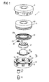
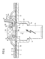
- FIG. 1 shows in connection with FIG. 2 an inventive airbag module 1.
- the airbag module 1 is a driver airbag module.
- teaching of the invention is also applicable to other types of airbag modules, in particular passenger airbag modules.
- the airbag module 1 has an airbag 2 and a diffuser 21 arranged in the airbag 2 for swirling gases generated by a gas generator 30.
- the diffuser 21 is cap-shaped and has a peripheral flange 22 connected to the diffuser 21, which can be detachably (eg screwed) or non-detachable (eg welded connection) connected to the diffuser 21 or integrally formed on the diffuser 21 ,
- the flange 22 is formed as a reservoir for storing a coolant 60.
- the airbag 2 and the diffuser 21 together with the flange 22 are arranged in a surrounding by a protective cover 40 interior 41 and form in this way together with said protective cover 40, a gas bag package 4.
- the interior 41 of the airbag package 4 is evacuated, so that airbag package 4 possible small construction fails.
- the gas generator 30 which is arranged in a predetermined by the diffuser 21 indentation of the airbag package 4, and that outside of the airbag package 4th
- a carrier 5 For carrying the airbag package 4 and the gas generator 30, a carrier 5 is provided, which has a floor 50 extending along an extension plane with a central, continuous gas generator recess 51, through which Gas generator 30 projects in sections, wherein the gas generator 30 is fixed via a peripheral flange 31 of the gas generator 30 to a gas generator recess 51 bordering edge region 52 of the bottom 50 of the carrier 5.
- a first direction R which preferably runs along the steering axis in a driver airbag module, projects from a wall 53 of the carrier 5, which rotates the gas generator 30 in a plane (extension plane of the bottom 50) that extends transversely to the first direction R.
- a cover 6 of the airbag module 1 is also defined, which covers the gas bag package 4 and the underlying gas generator 30.
- a movement generating device 70 in the form of a gas generator is provided at the bottom 50 of the carrier 5 by means of a sleeve 71, which sleeve 71 surrounds the gas generator 70 transversely to the first direction R.
- the motion generating device 70 has a cylindrical shape, wherein the cylinder axis is parallel to the first direction R.
- said sleeve 71 is preferably formed as a hollow cylinder.
- the movement generating device 70 is fixed to the carrier 5 so that the movement generating device 70 with a free end portion 72 along the first direction R is in through a formed on the bottom 50 through hole 54 in the carrier 5 of the airbag module 1 in.
- a sealing element 80 is provided (optionally), which surrounds the free end portion 72 of the movement generating device 70 transversely to the first direction R.
- the sleeve 71 on a free end portion 72 of the movement generating device 70 encircling edge portion 73 of the sleeve 71 has a groove 74 into which a passage opening 54 of the carrier 5 surging edge 55 of Bottom 50 of the carrier 5 engages, so that the sleeve 71 is fixed to the bottom 50 of the carrier 5.
- the sleeve 71 further has an inner side 75 facing the movement-generating device 70, on which a groove 76 is likewise formed, in which a circumferential region 77 of the movement-generating device 70 engages, so that the movement-generating device 70 is firmly seated in the sleeve 71.
- the sleeve 71 is dimensioned so that the movement generating device 70 projects with its free end portion 72 along the first direction R in the carrier 5 of the airbag module.
- the optional sealing element 80 engages around the free end portion 72 of the movement generating device 70 transversely to the first direction R closed annular.
- the passage opening 54 of the bottom 50 of the carrier 5 is located along the first direction R a congruent, further passage opening 23 (in the FIG. 1 not visible) of the circumferential, designed as a reservoir clamping element 22 opposite.
- the free end portion 72 of the movement generating device 71 may also be introduced, projecting from a peripheral region 24 of that further passage opening 23 along the first direction R, a wall 25 which rotates said free end portion 72 of the movement generating device 70 transversely to the first direction R. wherein the free end portion 72 of the movement generating device 70 may be inserted into the further through hole 23 so that the free end portion 72 encompassing sealing element 80 presses the protective cover 40 of the airbag package 4 against that wall 25. If no such sealing element 80 is present, the movement generating device 70 may be configured and provided to press the protective cover 40 of the airbag package 4 against that wall 25 via its free end section 72.
- the sealing element 80 thus serves, on the one hand, to protect the protective covering 40 of the airbag package 4.
- the sealing element 80 has an encircling extension 26 which extends transversely to the first direction R and which extends along the first direction R between mutually facing edge regions of the two through-openings 54, 23 is arranged, such that it seals those two through holes 54, 23.
- the further passage opening 23 of the clamping element 22 is therefore only of the Protective cover 40 closed.
- a region 42, which covers the further through-opening 23, of that protective covering 40 faces a front side 78 of the movement-generating device 70 which extends transversely to the first direction R.
- Said clamping element 22 forms a reservoir for a cooling liquid 60 circulating around the gas generator 30, it being possible to introduce pressure into the reservoir 22 via the said further passage 23.
- the said reservoir 22 is divided along the first direction R into two parts 27, 28, namely a first part 28 and a second part 27 which are liquid-tight by a movable element 90 in the form of a flexible membrane are separated from each other, wherein said membrane 90 is annular in area and in particular the gas generator 30 rotates transversely to the first direction R.
- a pressure for example by generating combustion gases (gas generator), destroy these hot gases the end face 78 of the movement generating device 70 opposite region 42 of the protective cover 40, penetrate through the further passage opening 23 therethrough into the first part 28 of the reservoir 22 and act on the transversely to the first direction R extending, located in an initial position membrane 90 of the reservoir 22.
- the diaphragm 90 movable member
- the membrane 90 may be in the initial position - as in the FIG. 2 shown - but also plan to extend along a plane.
- the membrane 90 along the first direction R is pressed away from the bottom 50 of the carrier 5, so that a possibly Reverses the existing curvature and points now in the first direction R.
- the membrane 90 takes along the cooling liquid 60 along the first direction R and places it through the outflow openings 100 of the reservoir 22 in the area surrounded by the airbag 2 Interior 29 of the airbag 2 free.
- Those outflow openings 100 are in this case formed on an upper side 22a of the circulating reservoir 22 (clamping element or circumferential flange of the diffuser) facing the interior 29 of the airbag 2.
- the outflow openings 100 of the reservoir 22 are provided with closures which are destroyed (opened) as a result of the pressure imparted by the membrane 90.
- the said reservoir 22 is arranged in the interior 29 of the airbag 2.
- the reservoir 22 defines the gas bag 2 of the gas bag package 4 on the carrier 5 of the airbag module 1.
- a peripheral edge region 2 a of an inflow opening of the airbag 2, through which the diffuser 21 and the reservoir 22 are introduced into the interior 29 of the airbag 2 is clamped between the bottom 50 of the carrier 5 and the said reservoir 22.
- the movement generating device 70 can be triggered by a sensor system for releasing the coolant 60 at any time, before, during and after the airbag 2 is inflated.
- the time of triggering of the movement-generating device 70 can preferably be calculated by means of evaluation electronics, namely Depending on the parameters detected by the sensor, such as the size (weight) and the position of an occupant to be protected relative to the airbag 2.
- the determination of the timing of the triggering of the movement generating device 70 can be done in real time.
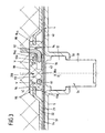
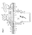
- FIG. 3 shows in connection with the FIGS. 4 to 7 a further embodiment of an airbag module according to the invention, with a gas bag package 4 and a carrier 5 in the manner of FIGS. 1 and 2 ,
- no reservoir 22 is provided with a cooling liquid 60, but a mechanism for triggering a tether 92 which opens in an exposed, not energized state, a discharge opening (not shown) of the airbag 2.
- two adjacent passage openings are formed on a circumferential flange 22 of a diffuser 21, which can serve in the manner already described for clamping a gas bag 2 on the bottom 50 of the carrier 5 of the airbag module 1, referred to as the first and second openings 93, 94, with depending on a peripheral edge region 93a, 94a, to which a holding element 95 is molded for the tether 92, so that that holding element 95, the first, larger opening 93 closes and leaves the second opening 94 in sections.
- the holding element 95 has a movable element 90, which is arranged in the first opening 93 and is connected via a circumferential predetermined breaking connection V with a frame 96 of the holding element 95. About this frame 96, the holding element 95 is preferably connected to the flange 22.
- movable element 90 is opposite to the first direction R from a free end portion 90 a of the movable member 90 from around which a loop formed at a free end of the tether 92 97 is wrapped.
- a departing from this loop 97 middle portion 98 of the tether 92 is now from the bottom 50 of the carrier 5 facing side of the flange 22 of the diffuser 21 forth through the exposed second opening 94 on a bottom 50 of the carrier 5 of the airbag module 1 side facing away the flange 22 is guided.
- the said catching strap 92 is thus fixed to the flange 22 of the diffuser 21. That middle section 98 of the tether 92 cooperates suitably with a discharge opening of the airbag 2, such that that outflow opening is closed with an inflated airbag 2, as long as the tether 92 on the movable member 90 and the free end portion 90 a of the movable member 90th Around loop 97 is fixed to the flange 22 of the diffuser 21.
- the holding element 95 in particular the movable element 90 is located with its free end portion 90 a, around which said loop 97 of the tether 92 is wrapped, along the first direction R of the end face 78 of the free end portion 72 of the movement generating device 70 opposite.
- the movement generating device 70 itself is seated in a passage opening 54 of the bottom 50 of the carrier 5 of the airbag module 1, according to FIG FIG. 3 that passage opening 54 of the bottom 50 of the carrier 5 is formed in a region of the carrier 5 projecting from the bottom 50 counter to the first direction R.
- the free end portion 72 of the motion generating device 70 which projects into the carrier 5 engages behind a peripheral edge region 55 of said through opening 54 of the bottom 50 of the carrier 5. If the motion generating device 70 is triggered, this can lead to a happen any time that can be determined by an evaluation in real time (preferably, depending on the size (weight) and the position of a person to be protected with respect to the airbag), the movement generating device 70 acts on a portion 42 of the protective cover 40, along the first direction R is opposite the movable member 90, with a hot gas, so that that portion 42 of the protective cover 40 is severed and the underlying movable member 90 is subjected to a corresponding pressure.
- the movable element 90 itself can close a discharge opening 200 of the airbag module 1 formed on the diffuser 21, in particular on the flange 22, in its initial position, which can be formed by the first opening 93.
- the movable member 90 releases the discharge port 200 when it is moved out of its initial position (by destroying the predetermined breaking joint V).
- gases which are present in the gas bag 2 can then escape from the gas bag 2 and, if appropriate, be discharged into an outer space surrounding the airbag module 1. Possibly. can be dispensed with the tether 90, so that by means of the movable member 90, only provided on the diffuser 22 outlet opening 200 can be opened.
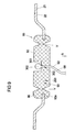
- FIGS. 8 and 9 show an alternative shape of the in the FIG. 6 shown movable element 90, wherein the tether 92 is not fixed by means of a loop 97 on the movable member 90.
- the movable element 90 has a recess 301 in which a free end portion 300 of the tether 92, which is integrally formed on the central portion 98 of the tether 92, permanently positively held (embedded), so that the movable member 90 when it is moved out of its initial position, the free end portion 300 of the tether 92 entrains.
- the free end portion 300 of the tether 92 passes through according to FIG. 9
- the movable element 90 when it is moved from its initial position, the free end portion 300 of the tether 92 with.
- the first opening 93 is present.
- This has the edge region 93a, to which the retaining element 95 is molded for the tether 92, so that the retaining element 95, the first opening 93 closes.
- the movable element 90 is in turn arranged in the first opening 93 and connected via a peripheral predetermined breaking connection V with a frame 96 of the holding element 95, which is molded onto the said edge region 93a.
- the first opening 93 can also form an outflow opening 200 of the airbag module 1 described above, so that if necessary also in the embodiments according to FIGS. 8 and 9 on a tether 92 (and arranged in the gas bag 2 discharge opening) can be omitted.
- the free end portion 72 of the motion generating device 70 along the first direction R in or before another through hole 23 of a arranged in the interior 41 of the airbag package component 4 of the 22 Airbag module 1 is arranged.
- passage opening 54 of the carrier 5 is aligned with the further passage opening 23 of that component 22.
- a peripheral wall 25 of the component 22 protrudes from a further through opening 23 bounding edge 24 along the first direction R, wherein that wall 25, the free end portion 72 of the movement generating device 70 rotates transversely to the first direction R, and wherein the free end portion 72 in particular on that wall 25 at least with the interposition of the protective cover 40 is present.
- an embodiment may be characterized by a sealing element 80 encircling the free end portion 72 of the movement generating device 70 in a plane extending transversely to the first direction R abutting the free end portion 72, wherein the protective cover 40 that sealing element 80 rotates along said plane, and wherein the free end portion 72 abuts in particular on the wall 25 with the interposition of the sealing element 80 and the protective cover 40.
- the reservoir 22 is formed by a circumferential flange of a diffuser 21 of the airbag module 1.
- the said part 21 is formed as a diffuser for distributing gases.
- the outflow opening 200 is formed on the diffuser 21.
- the tether 92 for fixing to the movable member 90 has a loop 97 which surrounds the located in the initial position movable member 90.
- a free end portion 300 of the tether 92 for fixing the tether 92 on the movable element 90 is arranged in a form-fitting manner in a recess 301 of the movable element 90.
- a free end portion 300 of the tether 92 for fixing the tether 92 on the movable member 90 in a through hole 302 of the movable member 90 is arranged, said free end portion 300 in particular a through opening 302 bordering edge portion 303 of the movable element 90th engages behind.
Description
Die Erfindung betrifft ein Airbagmodul für ein Kraftfahrzeug gemäß dem Oberbegriff des Anspruchs 1.The invention relates to an airbag module for a motor vehicle according to the preamble of claim 1.
Ein derartiges Airbagmodul weist ein Gassackpaket auf, umfassend einen Gassack, der zum Schutz einer Person mit Gas aufblasbar ist, ein zusätzliches bewegbares Element, das dazu eingerichtet und vorgesehen ist, eine Zustandsgröße des Gassackes zu beeinflussen, wobei es sich bei dieser Zustandsgröße um einen Druck des im Gassack befindlichen Gases handeln kann, und eine Schutzhülle, die einen Innenraum des Gassackpaketes gasdicht umgibt, wobei der Gassack und das bewegbare Element in jenem Innenraum angeordnet sind. Eine solche Schutzhülle kann aus einem flexiblen, auch elastischen Material gebildet sein. Vorzugsweise handelt es sich um eine Schutzhülle in Form einer Schutzfolie. Des Weiteren weist ein solches Airbagmodul eine dem bewegbaren Element zugeordnete Bewegungserzeugungsvorrichtung (Aktuator) auf, die dazu ausgebildet ist, das bewegbare Element anzutreiben.Such an airbag module has an airbag package, comprising an airbag which is inflatable to protect a person with gas, an additional movable element which is adapted and intended to influence a state variable of the airbag, wherein this state variable is a pressure the gas in the gas bag can act, and a protective cover, which surrounds an interior of the airbag package gas-tight, wherein the airbag and the movable member are arranged in that interior space. Such a protective cover may be formed of a flexible, also elastic material. Preferably, it is a protective cover in the form of a protective film. Furthermore, such an airbag module has a motion generating device (actuator) associated with the movable element, which is designed to drive the movable element.
In der gattungsgemäßen
Der Erfindung liegt das Problem zugrunde, ein Airbagmodul der eingangs genannten Art bereitzustellen, das im Hinblick auf den beanspruchten Bauraum verbessert ist.The invention is based on the problem to provide an airbag module of the type mentioned, which is improved in terms of the claimed space.
Dieses Problem wird durch ein Airbagmodul mit den Merkmalen des Anspruchs 1 gelöst.This problem is solved by an airbag module having the features of claim 1.
Danach ist vorgesehen, dass die Bewegungserzeugungsvorrichtung separat außerhalb des Innenraumes des Gassackpaketes angeordnet ist, also zumindest durch die Schutzhülle von den im Innenraum des Gassackpaketes angeordneten Komponenten des Airbagmoduls getrennt ist. Dies ermöglicht eine kleinbauende Ausführung des Gassackpaketes, da aufgrund der außerhalb des Gassackpaketes angeordneten Bewegungserzeugungsvorrichtung das Gassackpaket auf einfache Weise kompaktifiziert werden kann (durch Evakuieren des durch die Schutzhülle umgebenen Innenraumes des Gassackpaketes), insbesondere kann die Faltung des Gassackes einfacher ausfallen, da das Faltbild die Bewegungserzeugungsvorrichtung nicht berücksichtigen muss.Thereafter, it is provided that the movement generating device is arranged separately outside the interior of the airbag package, so at least by the protective cover of the arranged in the interior of the airbag package components the airbag module is disconnected. This allows a small-sized design of the airbag package, since due to the outside of the airbag package arranged movement generating device, the airbag package can be compacted in a simple manner (by evacuating the surrounded by the protective shell of the airbag package), in particular, the folding of the airbag can be simpler, since the folding picture the Motion generation device does not have to consider.
Das zum Aufblasen des Gassackes benötigte Gas wird vorzugsweise durch einen separaten, von der Bewegungserzeugungsvorrichtung verschiedenen Gasgenerator bereitgestellt, der insbesondere außerhalb des Innenraumes des Gassackpaketes angeordnet ist.The gas required for inflating the airbag is preferably provided by a separate, different from the movement generating device gas generator, which is arranged in particular outside the interior of the airbag package.
Bevorzugt ist die Bewegungserzeugungsvorrichtung dazu ausgebildet, das bewegbare Element aus einer Anfangsposition, in der das bewegbare Element nicht die besagte Zustandsgröße beeinflusst, derart herauszubewegen, dass das bewegbare Element die Zustandsgröße beeinflusst, wobei es sich vorzugsweise bei jener Zustandsgröße um den Druck des im Gassack befindlichen Gases handelt. Hierdurch kann der Gassack an das Gewicht (Größe) und die Position einer zu schützenden Person relativ zum Gassack angepasst werden. Es ist dabei bevorzugt vorgesehen, dass mittels des bewegbaren Elementes der besagte Druck insbesondere konstant (während des Aufblasvorganges) oder erniedrigt werden kann (z.B. im so genannten out-of-position-Fall, bei dem der zu schützende Insasse sich zu nah am Gassack befindet).Preferably, the movement generating device is configured to move the movable element out of an initial position in which the movable element does not influence said state variable such that the movable element influences the state variable, wherein the state variable is preferably the pressure of the gas bag Gas is trading. As a result, the gas bag can be adapted to the weight (size) and the position of a person to be protected relative to the gas bag. It is preferably provided that by means of the movable element of the said pressure in particular constant (during the inflation process) or can be lowered (eg in the so-called out-of-position case in which the occupant to be protected is too close to the airbag ).
Um das bewegbare Element aus dessen Anfangsposition heraus bewegen zu können, ist die Bewegungserzeugungsvorrichtung bevorzugt dazu ausgebildet, das bewegbare Element mit einem Druck zu beaufschlagen. Dieser Druck wird durch die Bewegungserzeugungsvorrichtung vorzugsweise pyrotechnisch bereitgestellt (Gasgenerator).In order to be able to move the movable element out of its initial position, the movement-generating device is preferably designed to apply a pressure to the movable element. This pressure is preferably provided pyrotechnically by the motion generating device (gas generator).
Um die Ausmaße des Gassackpaketes möglichst gering zu halten, ist der durch die Schutzhülle umgebene Innenraum vorzugsweise evakuiert, d.h., der im Innenraum des Gassackpaketes herrschende Druck ist signifikant niedriger als der atmosphärische Druck unter Standardbedingungen, so dass sich die Schutzhülle aufgrund des im Innenraum herrschenden Unterdrucks (vorzugsweise Vakuum) zusammenzieht und sich eng an die darin befindlichen Komponenten des Airbagmoduls anschmiegt.In order to keep the dimensions of the airbag package as low as possible, the interior surrounded by the protective cover is preferably evacuated, ie, the pressure prevailing in the interior of the airbag package is significantly lower than the atmospheric pressure under standard conditions, so that the protective cover due to the Inner space prevailing negative pressure (preferably vacuum) contracts and closely conforms to the components of the airbag module therein.
Des Weiteren weist das Airbagmodul zum Tragen von Komponenten des Airbagmoduls einen außerhalb des Innenraumes des Gassackpaketes angeordneten Träger auf, über den das Airbagmodul auch in oder an einem Kraftfahrzeug befestigt werden kann. Vorzugsweise ist die Bewegungserzeugungsvorrichtung an dem Träger befestigt.Furthermore, the airbag module for supporting components of the airbag module has a carrier arranged outside the interior of the airbag packet, by way of which the airbag module can also be fastened in or on a motor vehicle. Preferably, the movement generating device is attached to the carrier.
Weiterhin ist die Bewegungserzeugungsvorrichtung bevorzugt entlang einer ersten Richtung in eine am Träger ausgebildete Durchgangsöffnung eingeführt, so dass ein freier Endabschnitt der Bewegungserzeugungsvorrichtung, über den der Druck zum Beaufschlagen des bewegbaren Elementes bereitgestellt wird, entlang der ersten Richtung in den Träger des Airbagmoduls herein steht. Dabei liegt insbesondere ein Bereich der Schutzhülle einer quer zur ersten Richtung erstreckten Stirnseite der Bewegungserzeugungsvorrichtung gegenüber, wobei dieser Bereich der Schutzhülle durch den durch die Bewegungserzeugungsvorrichtung bereitgestellten Druck und /oder die Wärme eines den Druck vermittelnden Gases zerstört wird. Dieser beaufschlagt nämlich zuerst jenen Bereich der Schutzhülle und sodann das dahinter liegende bewegbare Element. Vorzugsweise liegt der freie Endabschnitt der Bewegungserzeugungsvorrichtung entlang der ersten Richtung dem bewegbaren Element gegenüber.Furthermore, the movement generating device is preferably inserted along a first direction into a passage opening formed on the carrier, so that a free end portion of the movement generating device, via which the pressure for urging the movable element is provided, enters the carrier of the airbag module along the first direction. In this case, in particular, a region of the protective sleeve faces a front side of the movement generating device which extends transversely to the first direction, this region of the protective sleeve being destroyed by the pressure and / or the heat of a pressure-conveying gas provided by the movement-generating device. Namely, this acts first on that area of the protective cover and then on the movable element behind it. Preferably, the free end portion of the motion generating device along the first direction is opposite to the movable element.
In einem Ausführungsbeispiel der Erfindung ist der freie Endabschnitt der Bewegungserzeugungsvorrichtung entlang der ersten Richtung in eine weitere Durchgangsöffnung einer im Innenraum des Gassackpaketes angeordneten Komponente des Airbagmoduls eingeführt oder ist entlang der ersten Richtung vor jener weiteren Durchgangsöffnung angeordnet, wobei jene weitere Durchgangsöffnung vorzugsweise mit der am Träger ausgebildeten Durchgangsöffnung fluchtet, d.h., die beiden Öffnungen liegen einander entlang der ersten Richtung gegenüber. Bei jener Komponente handelt es sich bevorzugt um ein Klemmelement, einen Flansch (eines Diffusors) oder ein Reservoir zum Speichern eines Kühlmittels. Jene Komponente kann die vorstehenden Funktionen auch in beliebiger Weise vereinen, also z.B. als ein Klemmelement für einen Gassack ausgebildet sein, wobei jenes Klemmelement ein Reservoir bildet. Bei jenem Klemmelement kann es sich des Weiteren um einen umlaufenden Flansch eines Diffusors handeln.In one embodiment of the invention, the free end portion of the movement generating device is inserted along the first direction in a further passage opening of a arranged in the interior of the airbag package component of the airbag module or is arranged along the first direction before that further passage opening, said further passage opening preferably with the carrier formed through opening is aligned, ie, the two openings are opposite to each other along the first direction. This component is preferably a clamping element, a flange (a diffuser) or a reservoir for storing a coolant. That component can also unite the above functions in any desired way, that is, for example, be formed as a clamping element for an airbag, wherein that clamping element a Reservoir forms. In that clamping element may further be a circumferential flange of a diffuser.
Jene weitere Durchgangsöffnung weist einen die weitere Durchgangsöffnung umlaufenden Rand auf, von dem in der ersten Richtung eine die weiterer Durchgangsöffnung umlaufende Wandung der besagten Komponente absteht, die den Endabschnitt quer zur ersten Richtung umgeben kann. Vorzugsweise liegt der freie Endabschnitt der Bewegungserzeugungsvorrichtung an jener Wandung an, und zwar zumindest unter Zwischenlage der Schutzhülle des Gassackpaketes.That further passage opening has a peripheral edge surrounding the further passage opening, from which, in the first direction, a wall of the said component running around the further passage opening projects, which can surround the end section transversely to the first direction. Preferably, the free end portion of the movement generating device is applied to that wall, at least with the interposition of the protective cover of the airbag package.
Optional ist ein den freien Endabschnitt der Bewegungserzeugungsvorrichtung quer zur ersten Richtung umgreifendes Dichtelement vorgesehen, das einerseits dem Schutz der Schutzhülle und andererseits zur Abdichtung der weiteren Durchgangsöffnung dient, wobei der besagte Endabschnitt unter Zwischenlage des Dichtelementes und der Schutzhülle an der Wandung anliegen kann. Dabei umgreift das Dichtelement den freien Endabschnitt und die Schutzhülle umgreift im Bereich des freien Endabschnittes jenes Dichtelement und den freien Endabschnitt der Bewegungserzeugungsvorrichtung.Optionally, a free end portion of the movement generating device encompassing the first direction encompassing sealing element is provided which serves on the one hand the protection of the protective cover and on the other hand for sealing the further passage opening, wherein said end portion may rest with the interposition of the sealing element and the protective cover on the wall. In this case, the sealing element surrounds the free end portion and the protective cover engages in the region of the free end portion that sealing element and the free end portion of the movement generating device.
Zum Tragen der Bewegungserzeugungsvorrichtung ist eine die Bewegungserzeugungsvorrichtung umgebene Hülse vorgesehen, die zum Festlegen der Bewegungserzeugungsvorrichtung am Träger des Airbagmoduls an einem umlaufenden Randbereich der Durchgangsöffnung des Trägers befestigt ist. Die Hülse dient dabei gleichzeitig zum Schutz der Bewegungserzeugungsvorrichtung.For carrying the movement-generating device, a sleeve surrounding the movement-generating device is provided, which is fastened to the carrier of the airbag module on a peripheral edge region of the through-opening of the carrier for fixing the movement-generating device. The sleeve serves at the same time to protect the movement generating device.
Bevorzugt ist die weitere, im Innenraum des Gassackpaketes vorgesehene Komponente als ein Klemmelement zum Festklemmen des Gassackes am Träger des Airbagmoduls ausgebildet, wobei das Klemmelement vorzugsweise durch einen umlaufenden Flansch eines Diffusors des Airbagmoduls gebildet ist. Ein solcher Diffusor ist dazu ausgebildet vom Gasgenerator ausgestoßene Gase zu verwirbeln.Preferably, the further, provided in the interior of the airbag package component is designed as a clamping element for clamping the airbag on the support of the airbag module, wherein the clamping element is preferably formed by a circumferential flange of a diffuser of the airbag module. Such a diffuser is designed to swirl gases emitted by the gas generator.
Besonders bevorzugt ist das Klemmelement als ein Reservoir ausgebildet, das dazu eingerichtet und vorgesehen ist, ein Kühlmittel aufzunehmen, das zum Kühlen im Gassack befindlicher Gase dient. Durch Kühlen von heißen, im Gassack befindlichen Gasen, kann der im Gassack herrschende Druck innerhalb kürzester Zeit abgesenkt werden. Dabei ist das bewegbare Element vorzugsweise dazu ausgebildet, beim Herausbewegen aus der Anfangsposition die Kühlflüssigkeit aus dem Reservoir heraus zu drücken, um das Kühlmittel in einen Innenraum des Gassackes freizusetzen. D.h., das druckbeaufschlagte bewegbare Element ist als Kolben ausgebildet, der den besagten Druck an die Kühlflüssigkeit weitergibt, indem er seinerseits die Kühlflüssigkeit mit Druck beaufschlagt. Die Kühlflüssigkeit wird hierdurch aus dem Reservoir ausgestoßen. Ein solcher Kolben kann natürlich auch in Form einer flexiblen Membran vorliegen.Particularly preferably, the clamping element is formed as a reservoir, which is adapted and intended to receive a coolant, which serves for cooling in the gas bag located gases. By cooling hot gases in the gas bag, the pressure prevailing in the gas bag can be lowered within a very short time become. In this case, the movable element is preferably designed to press the cooling liquid out of the reservoir when it moves out of the initial position in order to release the coolant into an interior space of the airbag. That is, the pressurized movable member is formed as a piston, which passes the said pressure to the cooling liquid by in turn pressurizing the cooling liquid. The cooling liquid is thereby expelled from the reservoir. Of course, such a piston can also be in the form of a flexible membrane.
In einer weiteren Ausführungsform der Erfindung ist das bewegbare Element dazu ausgebildet, in seiner Anfangsposition eine Abströmöffnung des Airbagmoduls zu verschließen, durch die in einem geöffneten Zustand Gas aus dem Gassack in einen das Airbagmodul umgebenden Außenraum entweichen kann, wobei das bewegbare Element beim Herausbewegen aus der Anfangsposition die Abströmöffnung öffnet, so dass Gas aus dem Gassack durch jene Abströmöffnung hindurch aus dem Gassack abgelassen werden kann.In a further embodiment of the invention, the movable element is adapted to close in its initial position, an outflow opening of the airbag module through which in an open state gas from the gas bag can escape into an outer space surrounding the airbag module, wherein the movable element when moving out of the Initial position opens the discharge opening, so that gas can be discharged from the gas bag through that discharge opening from the gas bag.
Bevorzugt ist das bewegbare Element in seiner Anfangsposition an einem im Innenraum des Gassackpakets angeordneten Teil des Airbagmoduls befestigt, wobei es sich bei jenem Teil vorzugsweise um einen Diffusor zum Lenken in den Gassack einzuleitender Gase handelt.In its initial position, the movable element is preferably fastened to a part of the airbag module arranged in the interior of the airbag package, wherein that part is preferably a diffuser for steering gases to be introduced into the airbag.
Bevorzugt ist das bewegbare Element über eine Sollbruchverbindung an dem besagten Teil des Airbagmoduls festgelegt, wobei jene Sollbruchverbindung bevorzugt beim Herausbewegen des bewegbaren Elementes aus seiner Anfangsposition zerstört wird, so dass das bewegbare Element vorzugsweise frei beweglich ist.Preferably, the movable element is fixed via a predetermined breaking connection to said part of the airbag module, wherein said predetermined breaking connection is preferably destroyed when moving out of the movable element from its initial position, so that the movable element is preferably freely movable.
Besonders bevorzugt ist die besagte Abströmöffnung an einem Diffusor ausgebildet, und zwar insbesondere an einem Flansch des Diffusors, über den der Diffusor am Träger des Airbagmoduls festlegbar ist, wobei der Flansch auch zum Festklemmen des Gassackes am Träger des Airbagmoduls dienen kann.Particularly preferably, the said outflow opening is formed on a diffuser, in particular on a flange of the diffuser, via which the diffuser on the support of the airbag module can be fixed, wherein the flange can also serve to clamp the airbag on the support of the airbag module.
In einer weiteren Ausführungsform der Erfindung ist das bewegbare Element dazu ausgebildet, in seiner Anfangsposition ein Fangband am Träger festzulegen, so dass ein mit dem Fangband zusammenwirkender Verschluss einer Abströmöffnung des Gassackes jene am Gassack ausgebildete Abströmöffnung verschließt. Eine solche öffenbare Abströmöffnung dient zum Ablassen von Gas aus dem Gassack zum Beeinflussen des im Gassack herrschenden Druckes, so dass der Gassack gezielt an die Größe (Gewicht) und Position (relativ zum Gassack) einer zu schützenden Person angepasst werden kann. Das Fangband ist weiterhin vorzugsweise derart am bewegbaren Element festgelegt, dass das bewegbare Element das Fangband beim Herausbewegen aus der Anfangsposition freigibt, so dass das Fangband nicht mehr über das bewegbare Element am Träger des Airbagmoduls festgelegt ist. Dies bewirkt ein Öffnen des Verschlusses der Abströmöffnung. Der zugrunde liegende Öffnungsmechanismus kann dabei dergestalt ausgebildet sein, dass das Fangband bei einem in der Anfangsposition befindlichen bewegbaren Element unter Spannung steht und dabei einen Verschluss vor der Abströmöffnung hält, wobei sich das Fangband beim Herausbewegen des bewegbaren Elementes aus der Anfangsposition derart lockert, dass der Verschluss nicht länger vor der Abströmöffnung angeordnet ist und diese freigibt.In a further embodiment of the invention, the movable element is designed to fix a tether on the carrier in its initial position, so that a closure of a discharge opening of the gas bag, which cooperates with the catch strap, closes those outflow opening formed on the gas bag. Such an openable discharge opening is used for discharging gas from the gas bag for influencing the pressure prevailing in the gas bag, so that the gas bag can be adapted specifically to the size (weight) and position (relative to the gas bag) of a person to be protected. The tether is also preferably fixed to the movable member so that the movable member releases the tether when moving out of the initial position, so that the tether is no longer set on the movable member on the support of the airbag module. This causes an opening of the closure of the discharge opening. The underlying opening mechanism can be designed in such a way that the tether is under tension at a moving element located in the initial position while holding a closure in front of the discharge opening, wherein the tether loosens when moving out of the movable element from the initial position so that the Closure is no longer located in front of the discharge opening and this releases.
Bevorzugt ist das bewegbare Element in seiner Anfangsposition über eine Sollbruchverbindung an einem im Innenraum des Gassackpakets angeordneten Teil des Airbagmoduls festgelegt, bei dem es sich vorzugsweise um einen Flansch eines Diffusors des Airbagmoduls handelt. Die Sollbruchverbindung ist dazu eingerichtet und vorgesehen, beim Beaufschlagen des bewegbaren Elementes mit dem durch die Bewegungserzeugungsvorrichtung bereitgestellten Druck durchtrennt zu werden, so dass das bewegbare Element durch den besagten Druck aus seiner Anfangsposition heraus bewegt wird. Hierbei tritt die besagte Lockerung des Fangbandes auf.In its initial position, the movable element is preferably fixed via a predetermined breaking connection to a part of the airbag module arranged in the interior of the airbag package, which is preferably a flange of a diffuser of the airbag module. The predetermined breaking connection is set up and intended to be severed upon application of the movable element with the pressure provided by the movement generating device, so that the movable element is moved out of its initial position by the said pressure. In this case, the said relaxation of the tether occurs.
Natürlich kann das bewegbare Element sowohl als Verschluss einer am Airbagmodul (z.B. am Diffusor oder am Flansch des Diffusors) vorgesehenen Abströmöffnung dienen, als auch zum Freigeben eines Fangbandes, dass mit einer Abströmöffnung des Gassackes zusammenwirkt. Ggf. kann auf das Fangband bzw. auf die am Gassack ausgebildete Abströmöffnung verzichtet werden.Of course, the movable element may serve both as a closure for a discharge opening provided on the airbag module (for example, on the diffuser or on the flange of the diffuser) and for releasing a tether which cooperates with a discharge opening of the gas bag. Possibly. can be dispensed with the tether or on the outlet formed on the gas bag.
Zum Festlegen des Fangbandes am bewegbaren Bereich weist dieses an einem freien Ende eine Schlaufe auf, die um das bewegbare Element herumgelegt ist.To set the tether on the movable portion of this has at a free end a loop which is wrapped around the movable member.
Alternativ hierzu ist ein freier Endabschnitt des Fangbandes zum Festlegen des Fangbandes am bewegbaren Element formschlüssig in einer Ausnehmung des bewegbaren Elementes angeordnet.Alternatively, a free end portion of the tether for fixing the tether on the movable member is positively disposed in a recess of the movable member.
In einer weiteren alternativen Variante ist ein freier Endabschnitt des Fangbandes zum Festlegen des Fangbandes am bewegbaren Element in eine Durchgangsöffnung des bewegbaren Elementes eingeführt, wobei jener Endabschnitt insbesondere einen die Durchgangsöffnung berandenden Randbereich des bewegbaren Elementes hintergreift.In a further alternative variant, a free end portion of the tether for fixing the tether on the movable member is inserted into a through hole of the movable member, said end portion engages behind a particular edge of the movable element bordering the passage opening.
Die dargestellten Merkmale und Vorteile der Erfindung sollen anhand der nachfolgenden Figurenbeschreibungen von Ausführungsbeispielen verdeutlicht werden.The illustrated features and advantages of the invention will become apparent from the following description of exemplary embodiments.
Es zeigen:
- Fig. 1:
- eine Explosionsansicht einer Ausführungsform des erfindungsgemäßen Airbagmoduls,
- Fig. 2:
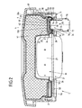
- eine geschnittene Ansicht des in der
Figur 1 gezeigten Airbagmoduls, - Fig. 3:
- eine ausschnitthafte Schnittdarstellung einer weiteren Ausführungsform des erfindungsgemäßen Airbagmoduls mit arretiertem Fangband,
- Fig. 4:
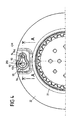
- eine ausschnitthafte Draufsicht auf einen Diffusor (samt Flansch) des in der
Figur 3 gezeigten Airbagmoduls, - Fig. 5:
- einen ausschnitthaften Schnitt entlang der Linie A-A der
Figur 4 , - Fig. 6:
- eine ausschnitthafte Schnittdarstellung des in der
Figur 3 gezeigten Airbagmoduls mit ausgelöster Bewegungserzeugungsvorrichtung, - Fig. 7:
- eine ausschnitthafte Schnittdarstellung des in
der Figur 6 gezeigten Airbagmoduls, wobei das druckbeaufschlagte bewegbare Element das Fangband freigegeben hat, - Fig. 8:
- einen alternativen Schnitt einer Abwandlung des in
der Figur 6 gezeigten bewegbaren Elementes, und - Fig. 9:
- einen weiteren alternativen Schnitt einer Abwandlung des in
der Figur 6 gezeigten bewegbaren Elementes.
- Fig. 1:
- an exploded view of an embodiment of the airbag module according to the invention,
- Fig. 2:
- a sectional view of the in the
FIG. 1 shown airbag module, - 3:
- 2 a sectional sectional view of a further embodiment of the airbag module according to the invention with a locked tether,
- 4:
- a fragmentary plan view of a diffuser (including flange) of the in the
FIG. 3 shown airbag module, - Fig. 5:
- a section along the line AA the
FIG. 4 . - Fig. 6:
- a fragmentary sectional view of the in the
FIG. 3 shown airbag module with triggered motion generating device, - Fig. 7:
- a fragmentary sectional view of the in the
FIG. 6 shown airbag module, wherein the pressurized movable element has released the tether, - Fig. 8:
- an alternative section of a modification of the in
FIG. 6 shown movable element, and - Fig. 9:
- another alternative section of a modification of the in
FIG. 6 shown movable element.
Das Airbagmodul 1 weist einen Gassack 2 und einen im Gassack 2 angeordneten Diffusor 21 zum Verwirbeln durch einen Gasgenerator 30 erzeugter Gase auf.The airbag module 1 has an
Der Diffusor 21 ist kappenförmig ausgebildet und weist einen mit dem Diffusor 21 verbundenen, umlaufenden Flansch 22 auf, der lösbar (z.B. Schraubverbindung) bzw. unlösbar (z.B. Schweißverbindung) mit dem Diffusor 21 verbunden sein kann oder aber einstückig an den Diffusor 21 angeformt sein kann. Der Flansch 22 ist dabei als ein Reservoir zum Speichern eines Kühlmittels 60 ausgebildet.The
Der Gassack 2 und der Diffusor 21 samt Flansch 22 sind in einem durch eine Schutzhülle 40 umgebenen Innenraum 41 angeordnet und bilden auf diese Weise zusammen mit der besagten Schutzhülle 40 ein Gassackpaket 4. Der Innenraum 41 des Gassackpaketes 4 ist evakuiert, so dass Gassackpaket 4 möglichst kleinbauend ausfällt.The
Zum Aufblasen des Gassackes 2 dient der Gasgenerator 30, der in einer durch den Diffusor 21 vorgegebenen Eindrückung des Gassackpaketes 4 angeordnet ist, und zwar außerhalb des Gassackpaketes 4.To inflate the
Zum Tragen des Gassackpaketes 4 und des Gasgenerators 30 ist ein Träger 5 vorgesehen, der einen entlang einer Erstreckungsebene erstreckten Boden 50 mit einer mittigen, durchgängigen Gasgeneratoraussparung 51 aufweist, durch die der Gasgenerator 30 abschnittsweise herausragt, wobei der Gasgenerator 30 über einen umlaufenden Flansch 31 des Gasgenerators 30 an einem die Gasgeneratoraussparung 51 berandenden Randbereich 52 des Bodens 50 des Trägers 5 festgelegt ist. Vom Boden 50 steht entlang einer ersten Richtung R, die bei einem Fahrerairbagmodul vorzugsweise entlang der Lenkachse verläuft, eine Wand 53 des Trägers 5 ab, die den Gasgenerator 30 in einer quer zur ersten Richtung R erstreckten Ebene (Erstreckungsebene des Bodens 50) umläuft. An jener Wand 53 ist ebenfalls eine Abdeckung 6 des Airbagmoduls 1 festgelegt, die das Gassackpaket 4 und den darunter liegenden Gasgenerator 30 überdeckt.For carrying the
Zum Freisetzen des im Reservoir 22 gespeicherten Kühlmittels 60 ist eine Bewegungserzeugungsvorrichtung 70 in Form eines Gasgenerators vorgesehen, die am Boden 50 des Trägers 5 mittels einer Hülse 71 festgelegt ist, wobei jene Hülse 71 den Gasgenerator 70 quer zur ersten Richtung R umgreift. Vorzugsweise weist die Bewegungserzeugungsvorrichtung 70 eine zylindrische Form auf, wobei die Zylinderachse parallel zur ersten Richtung R verläuft. Entsprechend ist die besagte Hülse 71 vorzugsweise als ein Hohlzylinder ausgebildet.In order to release the
Die Bewegungserzeugungsvorrichtung 70 ist so am Träger 5 festgelegt, dass die Bewegungserzeugungsvorrichtung 70 mit einem freien Endabschnitt 72 entlang der ersten Richtung R durch eine am Boden 50 ausgebildete Durchgangsöffnung 54 in den Träger 5 des Airbagmoduls 1 herein steht.The
Zum Abdichten der Durchgangsöffnung 54 des Bodens 50 und zum Schutz der Schutzhülle 40 ist (optional) ein Dichtelement 80 vorgesehen, das den freien Endabschnitt 72 der Bewegungserzeugungsvorrichtung 70 quer zur ersten Richtung R umgreift.For sealing the passage opening 54 of the bottom 50 and for protecting the
Die Einzelheiten der Anordnung der Bewegungserzeugungsvorrichtung 70 bezüglich des Reservoirs 22 sind in der Schnittdarstellung gemäß
Danach weist die Hülse 71 an einem den freien Endabschnitt 72 der Bewegungserzeugungsvorrichtung 70 umlaufenden Randbereich 73 der Hülse 71 eine Nut 74 auf, in die ein die Durchgangsöffnung 54 des Trägers 5 brandender Rand 55 des Bodens 50 des Trägers 5 eingreift, so dass die Hülse 71 am Boden 50 des Trägers 5 festgelegt ist. Die Hülse 71 weist weiterhin eine der Bewegungserzeugungsvorrichtung 70 zugewandte Innenseite 75 auf, an der ebenfalls eine Nut 76 ausgebildet ist, in die ein umlaufender Bereich 77 der Bewegungserzeugungsvorrichtung 70 eingreift, so dass die Bewegungserzeugungsvorrichtung 70 fest in der Hülse 71 sitzt.Thereafter, the
Die Hülse 71 ist so bemessen, dass die Bewegungserzeugungsvorrichtung 70 mit ihrem freien Endabschnitt 72 entlang der ersten Richtung R in den Träger 5 des Airbagmoduls hineinragt. Das optionale Dichtelement 80 umgreift dabei den freien Endabschnitt 72 der Bewegungserzeugungsvorrichtung 70 quer zur ersten Richtung R geschlossen ringförmig.The
Der Durchgangsöffnung 54 des Bodens 50 des Trägers 5 liegt entlang der ersten Richtung R eine deckungsgleiche, weitere Durchgangsöffnung 23 (in der
Das Dichtelement 80 dient somit zum einen zum Schutz der Schutzhülle 40 des Gassackpaketes 4. Zum anderen weist das Dichtelement 80 einen umlaufenden, quer zur ersten Richtung R erstreckten Fortsatz 26 auf, der entlang der ersten Richtung R zwischen einander zugewandten Randbereichen der beiden Durchgangsöffnungen 54, 23 angeordnet ist, derart, dass er jene beiden Durchgangsöffnungen 54, 23 abdichtet. Die weitere Durchgangsöffnung 23 des Klemmelementes 22 wird also lediglich von der Schutzhülle 40 verschlossen. Hierbei liegt ein die weitere Durchgangsöffnung 23 überdeckender Bereich 42 jener Schutzhülle 40 einer quer zur ersten Richtung R erstreckten Stirnseite 78 der Bewegungserzeugungsvorrichtung 70 gegenüber.The sealing
Das besagte Klemmelement 22 bildet ein den Gasgenerator 30 umlaufendes Reservoir für eine Kühlflüssigkeit 60 aus, wobei über die besagte weitere Durchgangsöffnung 23 Druck in das Reservoir 22 eingeleitet werden kann. Zum Herausdrücken der im Reservoir 22 befindlichen Kühlflüssigkeit 60 ist das besagte Reservoir 22 entlang der ersten Richtung R in zwei Teile 27, 28 unterteilt, nämlich einen ersten Teil 28 und einen zweiten Teil 27, die durch ein bewegbares Element 90 in Form einer flexiblen Membran flüssigkeitsdicht voneinander getrennt sind, wobei jene Membran 90 flächig ringförmig ausgebildet ist und insbesondere den Gasgenerator 30 quer zur ersten Richtung R umläuft.Said clamping
Stellt nun die Bewegungserzeugungsvorrichtung 70 über ihren freien Endabschnitt 72 einen Druck bereit, zum Beispiel durch ein Erzeugen von Verbrennungsgasen (Gasgenerator), zerstören diese heißen Gase den der Stirnseite 78 der Bewegungserzeugungsvorrichtung 70 gegenüberliegenden Bereich 42 der Schutzhülle 40, dringen durch die weitere Durchgangsöffnung 23 hindurch in den ersten Teil 28 des Reservoirs 22 ein und beaufschlagen die quer zur ersten Richtung R erstreckte, in einer Anfangsposition befindliche Membran 90 des Reservoirs 22. In der Anfangsposition kann die Membran 90 (bewegbares Element) dabei eine Wölbung in Richtung auf den Boden 50 des Trägers 5 aufweisen, so dass im zweiten Teil 27 des Reservoirs 22 ein entsprechendes Volumen zum Speichern des Kühlmittels 60 vorhanden ist. Die Membran 90 kann sich in der Anfangsposition - wie in der
Beim Beaufschlagen der dem Boden 50 des Trägers 5 zugewandten Seite 91 jener Membran 90 mit dem durch die Bewegungserzeugungsvorrichtung 70 bereitgestellten Druck (heiße Gase) wird die Membran 90 entlang der ersten Richtung R vom Boden 50 des Trägers 5 weg gedrückt, so dass sich eine ggf. vorhandene Wölbung umkehrt und nunmehr in die erste Richtung R weist. Hierbei nimmt die Membran 90 die Kühlflüssigkeit 60 entlang der ersten Richtung R mit und setzt sie durch die Ausströmöffnungen 100 des Reservoirs 22 in den vom Gassack 2 umgebenen Innenraum 29 des Gassackes 2 frei. Jene Ausströmöffnungen 100 sind dabei an einer dem Innenraum 29 des Gassackes 2 zugewandten Oberseite 22a des umlaufenden Reservoirs 22 (Klemmelement bzw. umlaufender Flansch des Diffusors) ausgebildet. Vorzugsweise sind die Ausströmöffnungen 100 des Reservoirs 22 mit Verschlüssen versehen, die infolge des durch die Membran 90 vermittelten Druckes zerstört (geöffnet) werden.When loading the bottom 50 of the
Damit das Kühlmittel 60 direkt in einen Innenraum 29 des Gassackes 2 verströmt werden kann, ist das besagte Reservoir 22 in dem Innenraum 29 des Gassackes 2 angeordnet. Gleichzeitig legt das Reservoir 22 den Gassack 2 des Gassackpaketes 4 am Träger 5 des Airbagmoduls 1 fest. Hierzu wird ein umlaufender Randbereich 2a einer Einströmöffnung des Gassackes 2, durch die hindurch der Diffusor 21 und das Reservoir 22 in den Innenraum 29 des Gassackes 2 eingeführt sind, zwischen dem Boden 50 des Trägers 5 und dem besagten Reservoir 22 festgeklemmt.So that the
Die Bewegungserzeugungsvorrichtung 70 kann zum Freisetzen des Kühlmittels 60 zu einem beliebigen Zeitpunkt durch eine Sensorik ausgelöst werden, und zwar vor, während und nach dem Aufblasen des Gassackes 2. Der Zeitpunkt des Auslösens der Bewegungserzeugungsvorrichtung 70 kann vorzugsweise durch eine Auswerteelektronik errechnet werden, und zwar in Abhängigkeit von durch die Sensorik erfassten Parametern, wie zum Beispiel der Größe (Gewicht) und der Position eines zu schützenden Insassen relativ zum Gassack 2. Die Bestimmung des Zeitpunktes der Auslösung der Bewegungserzeugungsvorrichtung 70 kann in Echtzeit erfolgen.The
Durch das Versprühen des Kühlmittels 60 in den Innenraum 29 des Gassackes 2 werden die dort befindlichen Gase gekühlt, so dass nach bekannten Gesetzen der Physik der in jenem Innenraum 29 des Gassackes 2 herrschende Druck entsprechend herabgesetzt wird.By spraying the
Im Gegensatz zu den
Hierzu sind an einem umlaufenden Flansch 22 eines Diffusors 21, der in bereits beschriebener Weise zum Festklemmen eines Gassackes 2 am Boden 50 des Trägers 5 des Airbagmoduls 1 dienen kann, zwei nebeneinander liegende Durchgangsöffnungen ausgebildet, bezeichnet als erste und zweite Öffnung 93, 94, mit je einem umlaufenden Randbereich 93a, 94a, an die ein Halteelement 95 für das Fangband 92 angespritzt ist, so dass jenes Halteelement 95 die erste, größere Öffnung 93 verschließt und die zweite Öffnung 94 abschnittsweise frei lässt. Das Halteelement 95 weist ein bewegbares Element 90 auf, das in der ersten Öffnung 93 angeordnet ist und über eine umlaufende Sollbruchverbindung V mit einem Rahmen 96 des Halteelementes 95 verbunden ist. Über diesen Rahmen 96 ist das Halteelement 95 vorzugsweise mit dem Flansch 22 verbunden.For this purpose, two adjacent passage openings are formed on a
Von jenem bewegbaren Element 90 steht entgegen der ersten Richtung R ein freier Endbereich 90a des bewegbaren Elementes 90 ab, um den eine an einem freien Ende des Fangbandes 92 ausgebildete Schlaufe 97 herumgelegt ist. Ein von dieser Schlaufe 97 abgehender mittlerer Abschnitt 98 des Fangbandes 92 ist nun von der dem Boden 50 des Trägers 5 zugewandten Seite des Flansches 22 des Diffusors 21 her durch die freigelassene zweite Öffnung 94 auf eine dem Boden 50 des Trägers 5 des Airbagmoduls 1 abgewandte Seite des Flansches 22 geführt.From that
Über die Schlaufe 97 ist das besagte Fangband 92 somit am Flansch 22 des Diffusors 21 festgelegt. Jener mittlere Abschnitt 98 des Fangbandes 92 wirkt geeignet mit einer Abströmöffnung des Gassackes 2 zusammen, derart, dass jene Abströmöffnung bei einem aufgeblasenen Gassack 2 verschlossen ist, solange das Fangband 92 über das bewegbare Element 90 und die um den freien Endbereich 90a des bewegbaren Elementes 90 herum gelegte Schlaufe 97 am Flansch 22 des Diffusors 21 festgelegt ist.Via the
Das Halteelement 95, insbesondere das bewegbare Element 90 liegt mit seinem freien Endbereich 90a, um den die besagte Schlaufe 97 des Fangbandes 92 herumgelegt ist, entlang der ersten Richtung R der Stirnseite 78 des freien Endabschnittes 72 der Bewegungserzeugungsvorrichtung 70 gegenüber. Entlang der ersten Richtung R sind lediglich die Schutzhülle 40 des Gassackpaketes 4 sowie gegebenenfalls ein Bereich des Gassackes 2 zwischen der Bewegungserzeugungsvorrichtung 70 und dem Halteelement 95 angeordnet. Die Bewegungserzeugungsvorrichtung 70 selbst sitzt in einer Durchgangsöffnung 54 des Bodens 50 des Trägers 5 des Airbagmoduls 1, wobei gemäß
Alternativ oder ergänzend zu dem vorstehend beschriebenen Fangbandmechanismus kann das bewegbare Element 90 selbst eine am Diffusor 21, insbesondere am Flansch 22, ausgebildete Abströmöffnung 200 des Airbagmoduls 1 in seiner Anfangsposition verschließen, die durch die erste Öffnung 93 gebildet sein kann.As an alternative or in addition to the above-described tether mechanism, the
Hierbei gibt das bewegbare Element 90 die besagte Abströmöffnung 200 frei, wenn es aus seiner Anfangsposition (unter Zerstörung der Sollbruchverbindung V) herausbewegt wird. Durch die am Diffusor 21 ausgebildete Abströmöffnung 200 können dann im Gassack 2 befindliche Gase aus dem Gassack 2 entweichen und ggf. in einen das Airbagmodul 1 umgebenden Außenraum abgeströmt werden. Ggf. kann auf das Fangband 90 verzichtet werden, so dass mittels des bewegbaren Elementes 90 lediglich die am Diffusor 22 vorgesehene Abströmöffnung 200 geöffnet werden kann.At this time, the
Die
Gemäß
Alternativ hierzu durchgreift der freie Endabschnitt 300 des Fangbandes 92 gemäß
Im Gegensatz zur
Insbesondere sollen noch einmal die folgenden Ausgestaltungen des Erfindungsgedankens herausgestellt werden: So ist in einem Ausführungsbeispiel vorgesehen, dass der freie Endabschnitt 72 der Bewegungserzeugungsvorrichtung 70 entlang der ersten Richtung R in oder vor einer weiteren Durchgangsöffnung 23 einer im Innenraum 41 des Gassackpaketes 4 angeordneten Komponente 22 des Airbagmoduls 1 angeordnet ist.In particular, the following embodiments of the inventive idea are again emphasized: Thus, in one embodiment, the
Weiterhin kann vorgesehen sein, dass die Durchgangsöffnung 54 des Trägers 5 mit der weiteren Durchgangsöffnung 23 jener Komponente 22 fluchtet.Furthermore, it can be provided that the passage opening 54 of the
Weiterhin kann vorgesehen sein, dass von einem die weitere Durchgangsöffnung 23 begrenzenden Rand 24 entlang der ersten Richtung R eine umlaufende Wandung 25 der Komponente 22 absteht, wobei jene Wandung 25 den freien Endabschnitt 72 der Bewegungserzeugungsvorrichtung 70 quer zur ersten Richtung R umläuft, und wobei der freie Endabschnitt 72 insbesondere an jener Wandung 25 zumindest unter Zwischenlage der Schutzhülle 40 anliegt.Furthermore, it can be provided that a
Weiterhin kann eine Ausführungsform gekennzeichnet sein durch ein den freien Endabschnitt 72 der Bewegungserzeugungsvorrichtung 70 in einer quer zur ersten Richtung R erstreckten Ebene umlaufendes Dichtelement 80, das am freien Endabschnitt 72 anliegt, wobei die Schutzhülle 40 jenes Dichtelement 80 entlang der besagten Ebene umläuft, und wobei der freie Endabschnitt 72 insbesondere an der Wandung 25 unter Zwischenlage des Dichtelementes 80 und der Schutzhülle 40 anliegt.Furthermore, an embodiment may be characterized by a sealing
Weiterhin kann vorgesehen sein, dass das Reservoir 22 durch einen umlaufenden Flansch eines Diffusors 21 des Airbagmoduls 1 gebildet ist.Furthermore, it can be provided that the
Weiterhin kann vorgesehen sein, dass das besagte Teil 21 als ein Diffusor zum Verteilen von Gasen ausgebildet ist.Furthermore, it can be provided that the said
Weiterhin kann vorgesehen sein, dass die Abströmöffnung 200 am Diffusor 21 ausgebildet ist.Furthermore, it can be provided that the
Weiterhin kann vorgesehen sein, dass das Fangband 92 zum Festlegen am bewegbaren Element 90 eine Schlaufe 97 aufweist, die das in der Anfangsposition befindliche bewegbare Element 90 umgreift.Furthermore, it can be provided that the
Weiterhin kann vorgesehen sein, dass ein freier Endabschnitt 300 des Fangbandes 92 zum Festlegen des Fangbandes 92 am bewegbaren Element 90 formschlüssig in einer Ausnehmung 301 des bewegbaren Elementes 90 angeordnet ist.Furthermore, it can be provided that a
Weiterhin kann vorgesehen sein, dass ein freier Endabschnitt 300 des Fangbandes 92 zum Festlegen des Fangbandes 92 am bewegbaren Element 90 in einer Durchgangsöffnung 302 des bewegbaren Elementes 90 angeordnet ist, wobei jener freie Endabschnitt 300 insbesondere einen die Durchgangsöffnung 302 berandenden Randbereich 303 des bewegbaren Elementes 90 hintergreift.Furthermore, it can be provided that a
Claims (15)
- Airbag module for a motor vehicle, comprising• a gas sack package (4), comprising- a gas sack (2),- an additional movable element (90) configured and provided to influence a state variable of the gas sack (2), and- a gas-tight protective covering (40) that defines an inner space (41) of the gas sack package (4), wherein the gas sack (2) and the moveable element (90) are arranged in said inner space (41), and• a movement generating device (70) configured and provided to move the moveable element (90), in order to influence the state variable,characterized in that
the movement generating device (70) is arranged separately outside the inner space (41) of the gas sack package (4), so that it is at least separated by the protective covering (40) from the components (2, 90) of the airbag module arranged in the inner space (41) of the gas sack package (4). - Airbag module according to claim 1, characterized in that the movement generating device (70) is configured and provided to move the movable element (90) out of an initial position, in which the movable element (90) does not influence said state variable, in a way that the movable element (90) influences said state variable.
- Airbag module according to claim 1 or 2, characterized in that the state variable is a pressure inside the gas sack (2).
- Airbag module according to one of the preceding claims, characterized in that the movement generating device (70) is configured and provided to act on the movable element (90) with a pressure, in order to move the movable element (90) out of the initial position, wherein the movement generating device (70) is particularly formed as a gas generator.
- Airbag module according to one of the preceding claims, characterized in that the inner space (41) of the gas sack package (4) is evacuated for compacting the gas sack package (4).
- Airbag module according to one of the preceding claims, characterized by a carrier (5) of the airbag module (1) for carrying the gas sack package (4), wherein particularly the movement generating device (70) is arranged on the carrier (5).
- Airbag module according to the claims 4 and 6, characterized in that the movement generating device (70) is arranged in a through-opening (54) of the carrier (5), so that a free end portion (72) of the movement generating device (70) via which the pressure for acting on the movable element (90) is provided, protrudes along a first direction (R) out of said through-opening (54), wherein particularly the free end portion (72) of the movement generating device (70) faces the movable element (90) along the first direction (R).
- Airbag module according to claim 7, characterized in that a region (42) of the protective covering (40) faces a front face (78) of the movement generating device (70) extending across the first direction (R), wherein said region (42) is destroyed, when the movement generating device (70) provides said pressure.
- Airbag module according to one of the claims 7 to 8, characterized in that the free end portion (72) of the movement generating device (70) is arranged along the first direction (R) in or in front of a further through-opening (23) of a component (22) of the airbag module (1) arranged in the inner space (41) of the gas sack package (4).
- Airbag module according to one of the claims 7 to 9, characterized by a shell (71) for carrying the movement generating device (70), wherein said shell (71) encompasses the movement generating device (70) and is, for fixing the movement generating device (70) to the carrier (5) of the airbag module (1), fixed to a circulating boundary region (55) of the through-opening (54) of the carrier (5).
- Airbag module according to claim 6 and according to claim 9 or claim 10 when referred back to claim 9, characterized in that the further component (22) is formed as a reservoir for storing a coolant (60), particularly as a reservoir in the form of a clamping element for clamping the gas sack (2) to the carrier (5) of the airbag module (1), wherein particularly the movable element (90) is configured and provided to press the coolant (60) out of the reservoir (22) upon moving out of the initial position, in order to set free the coolant (60) into an inner space (29) of the gas sack (2).
- Airbag module according to claim 2 and one of the claims 3 to 8 when referred back to claim 2, characterized in that the movable element (90) is fixed in its initial position to a part (21) of the airbag module (1) arranged in the inner space (41) of the gas sack package (4).
- Airbag module according to claim 12, characterized in that the movable element (90) is fixed through a predetermined breaking connection (V) to the part (21) of the airbag module, wherein said predetermined breaking connection (V), upon moving of the movable element (90) out of its initial position, is severed.
- Airbag module according to claim 2 or one of the claims 3 to 8, 12 to 13 when referred back to claim 2, characterized in that the movable element (90) is configured and provided to close a discharge opening (200) of the airbag module in its initial position, through which, in an opened state, gas can escape out of the gas sack (2), wherein the movable element (90) upon moving out of the initial position sets free the discharge opening (200), so that gas can escape through the discharge opening (200) out of the gas sack (2).
- Airbag module according to claim 2 or one of the claims 3 to 8, 12 to 14 when referred back to claim 2, characterized in that the movable element (90) is configured and provided to fix in its initial position a tether (92) to the airbag module in a way, that a closure of a discharge opening of the gas sack (2) interacting with the tether (92) closes said discharge opening, wherein the movable element (90) upon moving out of the initial position sets free the tether (92), so that said closure is opened.
Applications Claiming Priority (2)
| Application Number | Priority Date | Filing Date | Title |
|---|---|---|---|
| DE102008050759A DE102008050759B4 (en) | 2008-10-07 | 2008-10-07 | Airbag module for a motor vehicle |
| PCT/EP2009/062681 WO2010040669A1 (en) | 2008-10-07 | 2009-09-30 | Airbag module for a motor vehicle |
Publications (2)
| Publication Number | Publication Date |
|---|---|
| EP2334522A1 EP2334522A1 (en) | 2011-06-22 |
| EP2334522B1 true EP2334522B1 (en) | 2012-09-05 |
Family
ID=41393654
Family Applications (1)
| Application Number | Title | Priority Date | Filing Date |
|---|---|---|---|
| EP09743882A Not-in-force EP2334522B1 (en) | 2008-10-07 | 2009-09-30 | Airbag module for a motor vehicle |
Country Status (6)
| Country | Link |
|---|---|
| US (1) | US8109533B2 (en) |
| EP (1) | EP2334522B1 (en) |
| JP (1) | JP5443499B2 (en) |
| CN (1) | CN102123891B (en) |
| DE (1) | DE102008050759B4 (en) |
| WO (1) | WO2010040669A1 (en) |
Families Citing this family (4)
| Publication number | Priority date | Publication date | Assignee | Title |
|---|---|---|---|---|
| DE102009055266A1 (en) * | 2009-12-23 | 2011-06-30 | Takata-Petri Ag, 63743 | Airbag module for a motor vehicle |
| FR3059092B1 (en) * | 2016-11-18 | 2018-12-14 | Safran Aircraft Engines | PYROTECHNIC DEVICE |
| DE202017105555U1 (en) * | 2017-09-14 | 2018-12-17 | Dalphi Metal Espana, S.A. | Inflation protection to prevent damage when inflating a gas bag |
| JP2023090502A (en) * | 2021-12-17 | 2023-06-29 | 豊田合成株式会社 | air bag device |
Family Cites Families (19)
| Publication number | Priority date | Publication date | Assignee | Title |
|---|---|---|---|---|
| DE10114208A1 (en) | 2001-03-23 | 2002-05-08 | Trw Automotive Safety Sys Gmbh | Gasbag module assembly process involves stowing at least one component in cover, creating negative pressure in cover and closing it, making it gastight |
| US6648371B2 (en) * | 2001-07-12 | 2003-11-18 | Delphi Technologies, Inc. | Variable venting air bag assembly |
| US20030107207A1 (en) * | 2001-10-12 | 2003-06-12 | Trw Inc. | Air bag module with vent cover |
| US6773030B2 (en) | 2002-07-24 | 2004-08-10 | Trw Vehicle Safety Systems Inc. | Air bag with vent |
| US7055856B2 (en) * | 2003-02-06 | 2006-06-06 | Key Safety Systems, Inc. | Airbag module for selectively venting airbag inflation gas |
| ES2283982T3 (en) * | 2003-04-16 | 2007-11-01 | Key Safety Systems, Inc. | AIRBAG MODULE WITH CONTROLLED EVACUATION OF INFLATION GAS. |
| DE102006013359A1 (en) | 2005-06-10 | 2006-12-14 | Takata-Petri Ag | Airbag module for a motor vehicle |
| DE102005060684A1 (en) | 2005-06-10 | 2006-12-21 | Takata-Petri Ag | Airbag module for motor vehicle has second flow outlet opening connected to gas outlet opening of gas generator in such way that gas flowing from this outlet opening is directly at least partially into outer chamber |
| DE202005011878U1 (en) * | 2005-07-21 | 2005-10-13 | Takata-Petri Ag | Airbag module for motor vehicle has protective casing enclosing gas generator body with opening(s) through which ignition device protrudes out of casing and sealed gas-tight by at least one sealing element |
| DE102005039419B4 (en) * | 2005-08-16 | 2011-01-13 | Takata-Petri Ag | Occupant restraint system |
| DE202005016457U1 (en) * | 2005-10-17 | 2006-01-19 | Takata-Petri Ag | Airbag module for a motor vehicle |
| JP4877733B2 (en) * | 2005-12-28 | 2012-02-15 | タカタ株式会社 | Manufacturing method of airbag module |
| DE102006010953A1 (en) * | 2006-03-03 | 2007-09-06 | Takata-Petri Ag | Airbag module for a motor vehicle |
| JP2007261411A (en) | 2006-03-28 | 2007-10-11 | Toyoda Gosei Co Ltd | Airbag device |
| JP4898271B2 (en) * | 2006-04-18 | 2012-03-14 | タカタ株式会社 | Airbag device, vehicle, and method of manufacturing airbag device |
| JP2008137588A (en) * | 2006-12-05 | 2008-06-19 | Toyoda Gosei Co Ltd | Actuator with working pin |
| DE202007003906U1 (en) * | 2007-03-12 | 2007-07-12 | Takata-Petri Ag | Airbag arrangements for a vehicle occupant restraint system |
| JP4885035B2 (en) * | 2007-03-30 | 2012-02-29 | 日本プラスト株式会社 | Airbag device |
| JP4996550B2 (en) * | 2008-06-11 | 2012-08-08 | タカタ株式会社 | Airbag device |
-
2008
- 2008-10-07 DE DE102008050759A patent/DE102008050759B4/en not_active Expired - Fee Related
-
2009
- 2009-09-30 WO PCT/EP2009/062681 patent/WO2010040669A1/en active Application Filing
- 2009-09-30 EP EP09743882A patent/EP2334522B1/en not_active Not-in-force
- 2009-09-30 JP JP2011529543A patent/JP5443499B2/en not_active Expired - Fee Related
- 2009-09-30 CN CN2009801319670A patent/CN102123891B/en not_active Expired - Fee Related
-
2011
- 2011-01-13 US US13/006,254 patent/US8109533B2/en not_active Expired - Fee Related
Also Published As
| Publication number | Publication date |
|---|---|
| WO2010040669A1 (en) | 2010-04-15 |
| US20110109065A1 (en) | 2011-05-12 |
| JP2012505097A (en) | 2012-03-01 |
| JP5443499B2 (en) | 2014-03-19 |
| EP2334522A1 (en) | 2011-06-22 |
| CN102123891A (en) | 2011-07-13 |
| US8109533B2 (en) | 2012-02-07 |
| DE102008050759A1 (en) | 2010-04-08 |
| DE102008050759B4 (en) | 2012-04-26 |
| CN102123891B (en) | 2013-08-28 |
Similar Documents
| Publication | Publication Date | Title |
|---|---|---|
| DE10210328B4 (en) | Airbag system for motor vehicles | |
| EP2019004B1 (en) | Airbag module for a motor vehicle | |
| DE4139042A1 (en) | CONTACT DEVICE FOR AN AIRBAG MODULE | |
| DE102009023961A1 (en) | Actuator with release bolt | |
| EP2334522B1 (en) | Airbag module for a motor vehicle | |
| EP1155924A2 (en) | Air bag module | |
| DE102006005540A1 (en) | Vehicle`s occupant protecting apparatus, has occupant protection device deployable away from vehicle roof into engagement with occupant`s head positioned against side structure to move head laterally away from side structure | |
| DE10204627B4 (en) | Inflator for airbags with initiator holder | |
| DE10122956B4 (en) | airbag module | |
| DE29907607U1 (en) | Protection device with gas bag for motor vehicle occupants | |
| EP1877288B1 (en) | Airbag module for a motor vehicle | |
| EP1238866B1 (en) | Airbag module | |
| EP2176096B1 (en) | Airbag module for a motor vehicle | |
| EP1890915B1 (en) | Airbag module | |
| DE102016213693A1 (en) | Gas generator assembly for a vehicle occupant restraint system | |
| DE202004000801U1 (en) | Device for actuating a vehicle security system | |
| DE102005027310A1 (en) | Automotive air bag has an external gas guide with strap to fixed attachment point | |
| DE202011001429U1 (en) | Airbag module for a motor vehicle | |
| DE102007053591A1 (en) | Gas bag module i.e. side gas bag module, for passenger restraint system, has gas generator arranged opposite to hole of casing in blown up condition of bag, and tape fastened within area of generator and to element | |
| DE112007003431T5 (en) | airbag module | |
| DE2143165A1 (en) | STEERING WHEEL FOR A MOTOR VEHICLE OR THE LIKE | |
| DE102012007406A1 (en) | Airbag device used in motor car, has pneumatic drive that drives holder inside the housing in responsive to release signal, and release device releases strap or airbag section from retaining position | |
| EP1893521B1 (en) | Airbag module for a motor vehicle | |
| EP1854679B1 (en) | Steering system with airbag for a motor vehicle | |
| DE102006060689A1 (en) | Opening device for a pressurized gas container's outflow opening sealed by a membrane, particularly for a clean-gas generator to inflate an airbag, uses a plunger moved by super pressure |
Legal Events
| Date | Code | Title | Description |
|---|---|---|---|
| PUAI | Public reference made under article 153(3) epc to a published international application that has entered the european phase |
Free format text: ORIGINAL CODE: 0009012 |
|
| 17P | Request for examination filed |
Effective date: 20110406 |
|
| AK | Designated contracting states |
Kind code of ref document: A1 Designated state(s): AT BE BG CH CY CZ DE DK EE ES FI FR GB GR HR HU IE IS IT LI LT LU LV MC MK MT NL NO PL PT RO SE SI SK SM TR |
|
| AX | Request for extension of the european patent |
Extension state: AL BA RS |
|
| DAX | Request for extension of the european patent (deleted) | ||
| GRAP | Despatch of communication of intention to grant a patent |
Free format text: ORIGINAL CODE: EPIDOSNIGR1 |
|
| RAP1 | Party data changed (applicant data changed or rights of an application transferred) |
Owner name: TAKATA AG |
|
| GRAS | Grant fee paid |
Free format text: ORIGINAL CODE: EPIDOSNIGR3 |
|
| GRAA | (expected) grant |
Free format text: ORIGINAL CODE: 0009210 |
|
| AK | Designated contracting states |
Kind code of ref document: B1 Designated state(s): AT BE BG CH CY CZ DE DK EE ES FI FR GB GR HR HU IE IS IT LI LT LU LV MC MK MT NL NO PL PT RO SE SI SK SM TR |
|
| REG | Reference to a national code |
Ref country code: GB Ref legal event code: FG4D Free format text: NOT ENGLISH |
|
| REG | Reference to a national code |
Ref country code: CH Ref legal event code: EP |
|
| REG | Reference to a national code |
Ref country code: AT Ref legal event code: REF Ref document number: 573958 Country of ref document: AT Kind code of ref document: T Effective date: 20120915 |
|
| REG | Reference to a national code |
Ref country code: IE Ref legal event code: FG4D Free format text: LANGUAGE OF EP DOCUMENT: GERMAN |
|
| REG | Reference to a national code |
Ref country code: DE Ref legal event code: R096 Ref document number: 502009004628 Country of ref document: DE Effective date: 20121025 |
|
| REG | Reference to a national code |
Ref country code: NL Ref legal event code: VDEP Effective date: 20120905 |
|
| PG25 | Lapsed in a contracting state [announced via postgrant information from national office to epo] |
Ref country code: HR Free format text: LAPSE BECAUSE OF FAILURE TO SUBMIT A TRANSLATION OF THE DESCRIPTION OR TO PAY THE FEE WITHIN THE PRESCRIBED TIME-LIMIT Effective date: 20120905 Ref country code: NO Free format text: LAPSE BECAUSE OF FAILURE TO SUBMIT A TRANSLATION OF THE DESCRIPTION OR TO PAY THE FEE WITHIN THE PRESCRIBED TIME-LIMIT Effective date: 20121205 Ref country code: LT Free format text: LAPSE BECAUSE OF FAILURE TO SUBMIT A TRANSLATION OF THE DESCRIPTION OR TO PAY THE FEE WITHIN THE PRESCRIBED TIME-LIMIT Effective date: 20120905 Ref country code: FI Free format text: LAPSE BECAUSE OF FAILURE TO SUBMIT A TRANSLATION OF THE DESCRIPTION OR TO PAY THE FEE WITHIN THE PRESCRIBED TIME-LIMIT Effective date: 20120905 |
|
| REG | Reference to a national code |
Ref country code: LT Ref legal event code: MG4D Effective date: 20120905 |
|
| PG25 | Lapsed in a contracting state [announced via postgrant information from national office to epo] |
Ref country code: LV Free format text: LAPSE BECAUSE OF FAILURE TO SUBMIT A TRANSLATION OF THE DESCRIPTION OR TO PAY THE FEE WITHIN THE PRESCRIBED TIME-LIMIT Effective date: 20120905 Ref country code: GR Free format text: LAPSE BECAUSE OF FAILURE TO SUBMIT A TRANSLATION OF THE DESCRIPTION OR TO PAY THE FEE WITHIN THE PRESCRIBED TIME-LIMIT Effective date: 20121206 Ref country code: SI Free format text: LAPSE BECAUSE OF FAILURE TO SUBMIT A TRANSLATION OF THE DESCRIPTION OR TO PAY THE FEE WITHIN THE PRESCRIBED TIME-LIMIT Effective date: 20120905 Ref country code: SE Free format text: LAPSE BECAUSE OF FAILURE TO SUBMIT A TRANSLATION OF THE DESCRIPTION OR TO PAY THE FEE WITHIN THE PRESCRIBED TIME-LIMIT Effective date: 20120905 |
|
| BERE | Be: lapsed |
Owner name: TAKATA A.G. Effective date: 20120930 |
|
| PG25 | Lapsed in a contracting state [announced via postgrant information from national office to epo] |
Ref country code: CZ Free format text: LAPSE BECAUSE OF FAILURE TO SUBMIT A TRANSLATION OF THE DESCRIPTION OR TO PAY THE FEE WITHIN THE PRESCRIBED TIME-LIMIT Effective date: 20120905 Ref country code: IS Free format text: LAPSE BECAUSE OF FAILURE TO SUBMIT A TRANSLATION OF THE DESCRIPTION OR TO PAY THE FEE WITHIN THE PRESCRIBED TIME-LIMIT Effective date: 20130105 Ref country code: ES Free format text: LAPSE BECAUSE OF FAILURE TO SUBMIT A TRANSLATION OF THE DESCRIPTION OR TO PAY THE FEE WITHIN THE PRESCRIBED TIME-LIMIT Effective date: 20121216 Ref country code: NL Free format text: LAPSE BECAUSE OF FAILURE TO SUBMIT A TRANSLATION OF THE DESCRIPTION OR TO PAY THE FEE WITHIN THE PRESCRIBED TIME-LIMIT Effective date: 20120905 Ref country code: RO Free format text: LAPSE BECAUSE OF FAILURE TO SUBMIT A TRANSLATION OF THE DESCRIPTION OR TO PAY THE FEE WITHIN THE PRESCRIBED TIME-LIMIT Effective date: 20120905 Ref country code: EE Free format text: LAPSE BECAUSE OF FAILURE TO SUBMIT A TRANSLATION OF THE DESCRIPTION OR TO PAY THE FEE WITHIN THE PRESCRIBED TIME-LIMIT Effective date: 20120905 Ref country code: MC Free format text: LAPSE BECAUSE OF NON-PAYMENT OF DUE FEES Effective date: 20120930 |
|
| PG25 | Lapsed in a contracting state [announced via postgrant information from national office to epo] |
Ref country code: PL Free format text: LAPSE BECAUSE OF FAILURE TO SUBMIT A TRANSLATION OF THE DESCRIPTION OR TO PAY THE FEE WITHIN THE PRESCRIBED TIME-LIMIT Effective date: 20120905 Ref country code: SK Free format text: LAPSE BECAUSE OF FAILURE TO SUBMIT A TRANSLATION OF THE DESCRIPTION OR TO PAY THE FEE WITHIN THE PRESCRIBED TIME-LIMIT Effective date: 20120905 Ref country code: PT Free format text: LAPSE BECAUSE OF FAILURE TO SUBMIT A TRANSLATION OF THE DESCRIPTION OR TO PAY THE FEE WITHIN THE PRESCRIBED TIME-LIMIT Effective date: 20130107 |
|
| REG | Reference to a national code |
Ref country code: IE Ref legal event code: MM4A |
|
| PLBE | No opposition filed within time limit |
Free format text: ORIGINAL CODE: 0009261 |
|
| STAA | Information on the status of an ep patent application or granted ep patent |
Free format text: STATUS: NO OPPOSITION FILED WITHIN TIME LIMIT |
|
| PG25 | Lapsed in a contracting state [announced via postgrant information from national office to epo] |
Ref country code: IE Free format text: LAPSE BECAUSE OF NON-PAYMENT OF DUE FEES Effective date: 20120930 Ref country code: DK Free format text: LAPSE BECAUSE OF FAILURE TO SUBMIT A TRANSLATION OF THE DESCRIPTION OR TO PAY THE FEE WITHIN THE PRESCRIBED TIME-LIMIT Effective date: 20120905 Ref country code: BE Free format text: LAPSE BECAUSE OF NON-PAYMENT OF DUE FEES Effective date: 20120930 Ref country code: BG Free format text: LAPSE BECAUSE OF FAILURE TO SUBMIT A TRANSLATION OF THE DESCRIPTION OR TO PAY THE FEE WITHIN THE PRESCRIBED TIME-LIMIT Effective date: 20121205 |
|
| REG | Reference to a national code |
Ref country code: FR Ref legal event code: ST Effective date: 20130628 |
|
| 26N | No opposition filed |
Effective date: 20130606 |
|
| PG25 | Lapsed in a contracting state [announced via postgrant information from national office to epo] |
Ref country code: FR Free format text: LAPSE BECAUSE OF NON-PAYMENT OF DUE FEES Effective date: 20121105 Ref country code: IT Free format text: LAPSE BECAUSE OF FAILURE TO SUBMIT A TRANSLATION OF THE DESCRIPTION OR TO PAY THE FEE WITHIN THE PRESCRIBED TIME-LIMIT Effective date: 20120905 |
|
| REG | Reference to a national code |
Ref country code: DE Ref legal event code: R097 Ref document number: 502009004628 Country of ref document: DE Effective date: 20130606 |
|
| PG25 | Lapsed in a contracting state [announced via postgrant information from national office to epo] |
Ref country code: MT Free format text: LAPSE BECAUSE OF FAILURE TO SUBMIT A TRANSLATION OF THE DESCRIPTION OR TO PAY THE FEE WITHIN THE PRESCRIBED TIME-LIMIT Effective date: 20120905 Ref country code: CY Free format text: LAPSE BECAUSE OF FAILURE TO SUBMIT A TRANSLATION OF THE DESCRIPTION OR TO PAY THE FEE WITHIN THE PRESCRIBED TIME-LIMIT Effective date: 20120905 |
|
| PG25 | Lapsed in a contracting state [announced via postgrant information from national office to epo] |
Ref country code: TR Free format text: LAPSE BECAUSE OF FAILURE TO SUBMIT A TRANSLATION OF THE DESCRIPTION OR TO PAY THE FEE WITHIN THE PRESCRIBED TIME-LIMIT Effective date: 20120905 |
|
| REG | Reference to a national code |
Ref country code: CH Ref legal event code: PL |
|
| GBPC | Gb: european patent ceased through non-payment of renewal fee |
Effective date: 20130930 |
|
| PG25 | Lapsed in a contracting state [announced via postgrant information from national office to epo] |
Ref country code: SM Free format text: LAPSE BECAUSE OF FAILURE TO SUBMIT A TRANSLATION OF THE DESCRIPTION OR TO PAY THE FEE WITHIN THE PRESCRIBED TIME-LIMIT Effective date: 20120905 Ref country code: LU Free format text: LAPSE BECAUSE OF NON-PAYMENT OF DUE FEES Effective date: 20120930 |
|
| PG25 | Lapsed in a contracting state [announced via postgrant information from national office to epo] |
Ref country code: HU Free format text: LAPSE BECAUSE OF FAILURE TO SUBMIT A TRANSLATION OF THE DESCRIPTION OR TO PAY THE FEE WITHIN THE PRESCRIBED TIME-LIMIT Effective date: 20090930 Ref country code: CH Free format text: LAPSE BECAUSE OF NON-PAYMENT OF DUE FEES Effective date: 20130930 Ref country code: LI Free format text: LAPSE BECAUSE OF NON-PAYMENT OF DUE FEES Effective date: 20130930 Ref country code: GB Free format text: LAPSE BECAUSE OF NON-PAYMENT OF DUE FEES Effective date: 20130930 |
|
| PG25 | Lapsed in a contracting state [announced via postgrant information from national office to epo] |
Ref country code: MK Free format text: LAPSE BECAUSE OF FAILURE TO SUBMIT A TRANSLATION OF THE DESCRIPTION OR TO PAY THE FEE WITHIN THE PRESCRIBED TIME-LIMIT Effective date: 20120905 |
|
| REG | Reference to a national code |
Ref country code: AT Ref legal event code: MM01 Ref document number: 573958 Country of ref document: AT Kind code of ref document: T Effective date: 20140930 |
|
| PG25 | Lapsed in a contracting state [announced via postgrant information from national office to epo] |
Ref country code: AT Free format text: LAPSE BECAUSE OF NON-PAYMENT OF DUE FEES Effective date: 20140930 |
|
| REG | Reference to a national code |
Ref country code: DE Ref legal event code: R082 Ref document number: 502009004628 Country of ref document: DE Representative=s name: MAIKOWSKI & NINNEMANN PATENTANWAELTE PARTNERSC, DE Ref country code: DE Ref legal event code: R081 Ref document number: 502009004628 Country of ref document: DE Owner name: JOYSON SAFETY SYSTEMS GERMANY GMBH, DE Free format text: FORMER OWNER: TAKATA AG, 63743 ASCHAFFENBURG, DE |
|
| PGFP | Annual fee paid to national office [announced via postgrant information from national office to epo] |
Ref country code: DE Payment date: 20191129 Year of fee payment: 11 |
|
| REG | Reference to a national code |
Ref country code: DE Ref legal event code: R119 Ref document number: 502009004628 Country of ref document: DE |
|
| PG25 | Lapsed in a contracting state [announced via postgrant information from national office to epo] |
Ref country code: DE Free format text: LAPSE BECAUSE OF NON-PAYMENT OF DUE FEES Effective date: 20210401 |