JP5443499B2 - Airbag module for automobile - Google Patents
Airbag module for automobile Download PDFInfo
- Publication number
- JP5443499B2 JP5443499B2 JP2011529543A JP2011529543A JP5443499B2 JP 5443499 B2 JP5443499 B2 JP 5443499B2 JP 2011529543 A JP2011529543 A JP 2011529543A JP 2011529543 A JP2011529543 A JP 2011529543A JP 5443499 B2 JP5443499 B2 JP 5443499B2
- Authority
- JP
- Japan
- Prior art keywords
- gas bag
- airbag module
- movable element
- opening
- gas
- Prior art date
- Legal status (The legal status is an assumption and is not a legal conclusion. Google has not performed a legal analysis and makes no representation as to the accuracy of the status listed.)
- Expired - Fee Related
Links
Images


Classifications
-
- B—PERFORMING OPERATIONS; TRANSPORTING
- B60—VEHICLES IN GENERAL
- B60R—VEHICLES, VEHICLE FITTINGS, OR VEHICLE PARTS, NOT OTHERWISE PROVIDED FOR
- B60R21/00—Arrangements or fittings on vehicles for protecting or preventing injuries to occupants or pedestrians in case of accidents or other traffic risks
- B60R21/02—Occupant safety arrangements or fittings, e.g. crash pads
- B60R21/16—Inflatable occupant restraints or confinements designed to inflate upon impact or impending impact, e.g. air bags
- B60R21/23—Inflatable members
- B60R21/239—Inflatable members characterised by their venting means
-
- B—PERFORMING OPERATIONS; TRANSPORTING
- B60—VEHICLES IN GENERAL
- B60R—VEHICLES, VEHICLE FITTINGS, OR VEHICLE PARTS, NOT OTHERWISE PROVIDED FOR
- B60R21/00—Arrangements or fittings on vehicles for protecting or preventing injuries to occupants or pedestrians in case of accidents or other traffic risks
- B60R21/02—Occupant safety arrangements or fittings, e.g. crash pads
- B60R21/16—Inflatable occupant restraints or confinements designed to inflate upon impact or impending impact, e.g. air bags
- B60R21/20—Arrangements for storing inflatable members in their non-use or deflated condition; Arrangement or mounting of air bag modules or components
- B60R21/201—Packaging straps or envelopes for inflatable members
-
- B—PERFORMING OPERATIONS; TRANSPORTING
- B60—VEHICLES IN GENERAL
- B60R—VEHICLES, VEHICLE FITTINGS, OR VEHICLE PARTS, NOT OTHERWISE PROVIDED FOR
- B60R21/00—Arrangements or fittings on vehicles for protecting or preventing injuries to occupants or pedestrians in case of accidents or other traffic risks
- B60R21/02—Occupant safety arrangements or fittings, e.g. crash pads
- B60R21/16—Inflatable occupant restraints or confinements designed to inflate upon impact or impending impact, e.g. air bags
- B60R21/23—Inflatable members
- B60R21/231—Inflatable members characterised by their shape, construction or spatial configuration
- B60R21/2334—Expansion control features
- B60R21/2338—Tethers
- B60R2021/23382—Internal tether means
- B60R2021/23384—Internal tether means having ends which are movable or detachable during deployment
-
- B—PERFORMING OPERATIONS; TRANSPORTING
- B60—VEHICLES IN GENERAL
- B60R—VEHICLES, VEHICLE FITTINGS, OR VEHICLE PARTS, NOT OTHERWISE PROVIDED FOR
- B60R21/00—Arrangements or fittings on vehicles for protecting or preventing injuries to occupants or pedestrians in case of accidents or other traffic risks
- B60R21/02—Occupant safety arrangements or fittings, e.g. crash pads
- B60R21/16—Inflatable occupant restraints or confinements designed to inflate upon impact or impending impact, e.g. air bags
- B60R21/23—Inflatable members
- B60R21/239—Inflatable members characterised by their venting means
- B60R2021/2395—Inflatable members characterised by their venting means comprising means to control the venting
-
- B—PERFORMING OPERATIONS; TRANSPORTING
- B60—VEHICLES IN GENERAL
- B60R—VEHICLES, VEHICLE FITTINGS, OR VEHICLE PARTS, NOT OTHERWISE PROVIDED FOR
- B60R21/00—Arrangements or fittings on vehicles for protecting or preventing injuries to occupants or pedestrians in case of accidents or other traffic risks
- B60R21/02—Occupant safety arrangements or fittings, e.g. crash pads
- B60R21/16—Inflatable occupant restraints or confinements designed to inflate upon impact or impending impact, e.g. air bags
- B60R21/26—Inflatable occupant restraints or confinements designed to inflate upon impact or impending impact, e.g. air bags characterised by the inflation fluid source or means to control inflation fluid flow
- B60R2021/26017—Inflatable occupant restraints or confinements designed to inflate upon impact or impending impact, e.g. air bags characterised by the inflation fluid source or means to control inflation fluid flow a cooling agent being added to the inflation fluid
-
- Y—GENERAL TAGGING OF NEW TECHNOLOGICAL DEVELOPMENTS; GENERAL TAGGING OF CROSS-SECTIONAL TECHNOLOGIES SPANNING OVER SEVERAL SECTIONS OF THE IPC; TECHNICAL SUBJECTS COVERED BY FORMER USPC CROSS-REFERENCE ART COLLECTIONS [XRACs] AND DIGESTS
- Y10—TECHNICAL SUBJECTS COVERED BY FORMER USPC
- Y10S—TECHNICAL SUBJECTS COVERED BY FORMER USPC CROSS-REFERENCE ART COLLECTIONS [XRACs] AND DIGESTS
- Y10S102/00—Ammunition and explosives
- Y10S102/704—Coolants
Description
本発明は、請求項1の前段部分(前文)に係る自動車用のエアバッグモジュールに関する。
The present invention relates to an airbag module for an automobile according to the front part (preface) of
そのようなエアバッグモジュールは、人を保護するべく膨張可能なガスバッグを有するガスバッグ包体と、ガスバッグの状態変数に影響を及ぼす(状態変数に作用する)よう追加で構成配置された可動要素を備え、ここでは前記状態変数をガスバッグ内のガスの圧力とすることができ、更にガスバッグ包体の内部空間を気密状に取り囲む保護カバーを備え、ガスバッグ及び可動要素が前記内部空間に配置される。そのような保護カバーを柔軟且つ伸縮性の素材によって形成することができる。保護フィルムの形態の保護カバーを用いるのが好ましい。更に、そのようなエアバッグモジュールは、可動要素に割り当てられて前記可動要素を作動させるよう構成された作動装置(アクチュエーター)を備えている。 Such an air bag module has a gas bag envelope with an inflatable gas bag to protect a person, and a moveable additionally configured to influence (act on) the state variables of the gas bag. And the state variable can be the pressure of the gas in the gas bag, and further includes a protective cover that hermetically surrounds the inner space of the gas bag envelope, and the gas bag and the movable element are disposed in the inner space. Placed in. Such a protective cover can be formed of a flexible and stretchable material. It is preferable to use a protective cover in the form of a protective film. Furthermore, such an airbag module comprises an actuating device (actuator) that is assigned to the movable element and is configured to actuate the movable element.
本発明の課題は、先述の種類のエアバッグモジュールにおいて使用される取り付け空間についての改良を図ることである。 An object of the present invention is to improve the mounting space used in the aforementioned type of airbag module.
この課題は、請求項1に記載の特徴を有するエアバッグモジュールによって達成される。
This object is achieved by an airbag module having the features of
これにより、作動装置は、ガスバッグ包体の内部空間の外側に分離して配設され、即ち保護カバーによってエアバッグモジュールのうちガスバッグ包体の内部空間に配設される構成要素とは少なくとも分離される。これにより、作動装置がガスバッグ包体の外側に配設されるため、ガスバッグ包体が小型である実施形態においては、(保護カバーによって取り囲まれるガスバッグ包体の内部空間が排気状態にされることによって)ガスバッグ包体を簡便に小型化することができ、特には保持状況が作動装置によらないためガスバッグをより簡便に保持することが可能となる。 Thus, the actuating device is separately disposed outside the internal space of the gas bag package, that is, the component disposed in the internal space of the gas bag package of the airbag module by the protective cover is at least To be separated. Thereby, since the operating device is disposed outside the gas bag package, in the embodiment in which the gas bag package is small, the internal space of the gas bag package surrounded by the protective cover is exhausted. Therefore, the gas bag can be easily reduced in size, and in particular, since the holding state does not depend on the operating device, the gas bag can be held more easily.
ガスバッグの膨張に必要なガスは、作動装置とは異なる分離型のガス発生器(「ガスジェネレータ」ともいう)によって供給されるのが好ましく、当該ガス発生器は、ガスバッグ包体の内部空間の外側に部分的に配設される。 The gas required for the expansion of the gas bag is preferably supplied by a separate gas generator (also referred to as “gas generator”) different from the operating device, and the gas generator is provided in the internal space of the gas bag package. Partially disposed on the outside.
好ましくは、作動装置は、可動要素が状態変数に影響しない初期位置を外れて、可動要素が前記状態変数に影響を及ぼすように当該可動要素を移動させる構成とされ、前記状態変数はガスバッグ内のガスの圧力とされるのが好ましい。ここで、ガスバッグを保護乗員の体重(体格)及びガスバッグに対する位置に適合させることができる。このため、前記圧力は(膨張動作の間は)一定とされ、或いは可動要素によって低下可能とされる(例えば、いわゆるアウト・オブ・ポジションの場合で、この場合には保護乗員がガスバッグに極端に近接して配置される)。 Preferably, the actuating device is configured to move the movable element so that the movable element moves out of the initial position where the movable element does not affect the state variable, and the movable element affects the state variable. Preferably, the gas pressure is Here, the gas bag can be adapted to the weight (physique) of the protective occupant and the position relative to the gas bag. For this reason, the pressure is constant (during the inflating operation) or can be lowered by a movable element (for example in the case of so-called out-of-position, in which case the protective occupant is extremely Placed close to).
可動要素をその初期位置から外れるように移動させるためには、作動装置は、可動要素に所定の圧力を作用させるよう構成されるのが好ましい。この圧力は、作動装置(ガス発生器)によって点火式の形態で付与されるのが好ましい。 In order to move the movable element away from its initial position, the actuating device is preferably configured to exert a predetermined pressure on the movable element. This pressure is preferably applied in the form of an ignition by an actuating device (gas generator).
ガスバッグ包体の大きさ(寸法)を極力小さく維持するために、保護カバーによって取り囲まれる内部空間が排気状態とされるのが好ましく、即ちガスバッグ包体の内部空間の圧力が標準状況下では大気圧よりも相当に低く、これにより保護カバーは、内部空間が低圧(好ましくは真空状態)となることで収縮し、またその内部空間に存在するエアバッグモジュールの構成要素に被着される。 In order to keep the size (dimension) of the gas bag envelope as small as possible, it is preferable that the internal space surrounded by the protective cover is in an exhausted state, that is, the pressure in the internal space of the gas bag envelope is under normal conditions. It is considerably lower than the atmospheric pressure, so that the protective cover contracts when the internal space becomes a low pressure (preferably in a vacuum state) and is attached to the components of the airbag module existing in the internal space.
更に、エアバッグモジュールは、エアバッグモジュールの構成要素を保持するべくガスバッグ包体の内部空間の外側に配設された保持体を備えており、エアバッグモジュールは、当該保持体によっても車両に固定可能とされる。好ましくは、作動装置が保持体に取り付け固定される。 Further, the airbag module includes a holding body disposed outside the inner space of the gas bag package so as to hold the components of the airbag module, and the airbag module is also attached to the vehicle by the holding body. It can be fixed. Preferably, the actuator is attached and fixed to the holding body.
更に、作動装置は、保持体内に形成された貫通開口に第1の方向に沿って挿入されるのが好ましく、これにより作動装置のうち可動装置に圧力を作用させる自由端部が、第1の方向に沿ってエアバッグモジュールの保持体内へと突出する。このため、特に保護カバーの所定の領域が、作動装置のうち第1の方向と交差して延在する前面に対向し、保護カバーの前記領域は、作動装置により付与される圧力によって及び/又は圧力をもたらすガスの熱によって破断される。即ち、ガスの熱は、最初に保護カバーの前記領域に作用し、その後にその裏側の可動要素に作用する。好ましくは、作動装置の自由端部が第1の方向に沿って可動要素に対向する。 Furthermore, the actuating device is preferably inserted along a first direction into a through-opening formed in the holding body, so that the free end portion that applies pressure to the movable device of the actuating device has a first end. It projects into the holding body of the airbag module along the direction. For this reason, in particular, a predetermined area of the protective cover faces the front surface of the actuating device that extends across the first direction, and said area of the protective cover depends on the pressure applied by the actuating device and / or It is broken by the heat of the gas that brings pressure. That is, the heat of the gas first acts on the area of the protective cover and then acts on the movable element behind it. Preferably, the free end of the actuating device faces the movable element along the first direction.
本発明の一実施形態では、作動装置の自由端部は、エアバッグモジュールのうちガスバッグ包体の内部空間に配設された、或いは第1の方向に沿って別の貫通開口の前方に配設された構成要素の別の貫通開口内へと、第1の方向に沿って挿入され、前記別の貫通開口は、好ましくは保持体に形成された別の貫通開口と一直線上に配置される、即ち2つの開口が第1の方向に沿って互いに対向する。好ましくは、前記構成要素は、クランプ要素(「固定要素」ないし「係止要素」ともいう)、(ディフューザー(ガス拡散用の「拡散器」ないし「散気装置」ともいう)の)フランジ、又は冷却液(クーラント)を貯留する貯留部(リザーバー)として構成され得る。前記構成要素は、前述の機能を任意の形態で統合することもでき、即ちガスバッグ用のクランプ要素として構成可能とされ、前記クランプ要素が貯留部を形成する。更に、前記クランプ要素をディフューザーの環状のフランジとして構成することもできる。 In one embodiment of the present invention, the free end of the actuating device is disposed in the interior space of the gas bag package of the airbag module or arranged in front of another through-opening along the first direction. Inserted in a first direction into another through-opening of the component provided, said another through-opening being preferably arranged in line with another through-opening formed in the holding body That is, the two openings face each other along the first direction. Preferably, said component is a clamping element (also referred to as “fixing element” or “locking element”), a flange (of a diffuser (also referred to as “diffuser” or “aeration device” for gas diffusion)), or It can be configured as a reservoir (reservoir) that stores a coolant (coolant). The component can also integrate the aforementioned functions in any form, i.e. it can be configured as a clamping element for a gas bag, and the clamping element forms a reservoir. Furthermore, the clamping element can also be configured as an annular flange of the diffuser.
前記別の貫通開口は、別の貫通開口を循環する端部領域を有し、貫通開口を循環する壁部が当該端部領域から第1の方向に突出し、当該壁部は、第1の方向と交差して自由端部を取り囲むことができる。好ましくは、作動装置の自由端部が前記壁部に、即ちガスバッグ包体の保護カバーの少なくとも介在部に当接する。 The another through-opening has an end region that circulates through the other through-opening, and a wall portion that circulates through the through-opening protrudes from the end region in the first direction, and the wall portion extends in the first direction. And can surround the free end. Preferably, the free end of the actuating device contacts the wall, that is, at least the intervening portion of the protective cover of the gas bag envelope.
必要に応じては、第1の方向と交差して作動装置の自由端部を取り囲むシール要素が設けられ、当該シール要素は、一方では保護カバーを保護する機能を、他方では別の貫通開口を密閉状にシールする機能を果たし、前記自由端部は、シール要素と保護カバーとの介在部にて壁部に当接可能とされる。このため、シール要素が自由端部を取り囲み、また保護カバーは、自由端部の領域にて前記シール要素と作動装置の自由端部を取り囲む。 If necessary, a sealing element is provided which intersects the first direction and surrounds the free end of the actuator, the sealing element on the one hand functioning to protect the protective cover and on the other hand to another through-opening. It functions to seal hermetically, and the free end can be brought into contact with the wall at the interposed portion between the sealing element and the protective cover. For this purpose, the sealing element surrounds the free end, and the protective cover surrounds the sealing element and the free end of the actuating device in the region of the free end.
作動装置を保持するべくこの作動装置を取り囲むシェルが設けられ、当該シェルは、作動装置をエアバッグモジュールの保持体に固定するべく、保持体の貫通開口の環状の端部領域に取り付けられる。 A shell is provided surrounding the actuating device to hold the actuating device, and the shell is attached to the annular end region of the through opening of the holding body to secure the actuating device to the holding body of the airbag module.
好ましくは、ガスバッグ包体の内部空間に設けられた別の構成要素が、ガスバッグをエアバッグモジュールの保持体に固定するためのクランプ要素として構成され、このクランプ要素は、エアバッグモジュールのディフューザーの環状のフランジによって構成される。そのようなディフューザーは、ガス発生器によって吐出されたガスを旋回させるように構成される。 Preferably, another component provided in the interior space of the gas bag enclosure is configured as a clamp element for fixing the gas bag to the holding body of the airbag module, and the clamp element is a diffuser of the airbag module. It is comprised by the annular flange. Such a diffuser is configured to swirl the gas discharged by the gas generator.
特に好ましくは、クランプ要素は、ガスバッグ内のガスを冷却する機能を果たす冷却液を貯留する貯留部として構成される。ガスバッグ内の高温ガスの冷却によって、ガスバッグ内の圧力が短時間のうちに低下可能とされる。このため、可動要素は、初期位置を外れて移動する際、ガスバッグの内部空間へと冷却液を放出するべく冷却液を貯留部外へと押し出すように構成されるのが好ましい。換言すれば、加圧された可動要素は、冷却液の一部に所定圧力を作用させることによって冷却液に前記圧力を伝達するピストンとして構成される。ここで、冷却液が貯留部外へと排出される。勿論、そのようなピストンを柔軟な膜によって構成することもできる。 Particularly preferably, the clamping element is configured as a reservoir for storing a coolant that performs the function of cooling the gas in the gas bag. By cooling the hot gas in the gas bag, the pressure in the gas bag can be reduced in a short time. For this reason, when the movable element moves out of the initial position, it is preferable that the movable element is configured to push the cooling liquid out of the storage portion so as to discharge the cooling liquid into the internal space of the gas bag. In other words, the pressurized movable element is configured as a piston that transmits the pressure to the coolant by applying a predetermined pressure to a part of the coolant. Here, the coolant is discharged out of the reservoir. Of course, such a piston can also be constituted by a flexible membrane.
本発明の別の実施形態では、可動要素は、その初期位置にてエアバッグモジュールの吐出開口を閉鎖するように構成され、開放状態ではガスは当該吐出開口を通じてガスバッグ外へエアバッグモジュールを取り囲む外側空間へと排出可能とされ、初期位置を外れて移動する際、可動要素が吐出開口を開放し、これによりガスバッグ外の前記吐出開口を通じてガスバッグ外へとガスが吐出可能とされる。 In another embodiment of the invention, the movable element is configured to close the discharge opening of the airbag module in its initial position, and in the open state the gas surrounds the airbag module out of the gas bag through the discharge opening. When the movable element can be discharged to the outer space and moves out of the initial position, the movable element opens the discharge opening, whereby gas can be discharged out of the gas bag through the discharge opening outside the gas bag.
好ましくは、可動要素はその吐出位置においてエアバッグモジュールのうちガスバッグ包体の内部空間に配設された部位に取り付けられ、前記部位は、ガスバッグ内へと吐出されるガスを誘導するディフューザーとされるのが好ましい。 Preferably, the movable element is attached to a portion of the airbag module disposed in the internal space of the gas bag package at the discharge position, and the portion includes a diffuser that guides gas discharged into the gas bag. Preferably it is done.
好ましくは、可動要素は、規定の開裂接続部を介してエアバッグモジュールの前記部位に固定され、前記規定の開裂接続部は、可動要素がその初期位置を外れて移動する際に開裂するのが好ましく、これにより可動要素は移動自在されるのが好ましい。 Preferably, the movable element is fixed to the part of the airbag module via a defined tear connection, the defined tear connection being cleaved when the movable element moves out of its initial position. Preferably, this makes the movable element movable.
特に好ましくは、前記吐出開口はディフューザーに、即ち特にはディフューザーのフランジに設けられ、ディフューザーは、当該フランジを介してエアバッグモジュールの保持体に固定可能とされ、このフランジは、ガスバッグをエアバッグモジュールの保持体に固定する機能を果たすこともできる。 Particularly preferably, the discharge opening is provided in the diffuser, i.e. in particular in the flange of the diffuser, the diffuser being fixable to the holding body of the airbag module via the flange, this flange being able to fix the gas bag to the airbag It can also serve to fix to the module holder.
本発明の別の実施形態では、可動要素はその初期位置においてテザーを保持体に固定するよう構成され、これによりテザーと相互作用するガスバッグの吐出開口の閉鎖部によって、ガスバッグ内に形成された前記吐出開口が閉鎖される。そのような開放が可能とされた吐出開口は、ガスバッグ内の圧力に影響を及ぼす(圧力に作用する)べく、ガスバッグ外へとガスを吐出する機能を果たし、これにより保護乗員の体格(体重)及び(ガスバッグに対する)位置にガスバッグを正確に適合させることができる。好ましくは、テザーは更に、可動要素が初期位置を外れて移動する際にテザーを解放するように可動要素に固定され、これによりテザーはもはや可動要素によってはエアバッグモジュールの保持体に固定されない。これにより、吐出開口の閉鎖部が開放される。従って、この開放機構では基本的に可動要素がその初期位置にあり、これにより吐出開口の前方で閉鎖部を保持する場合に、テザーに張力が作用するよう構成することができ、テザーは、可動要素が初期位置を外れて移動する際、閉鎖部がもはや吐出開口の前方に配設されず解放されるように緩められる。 In another embodiment of the invention, the movable element is configured to secure the tether to the retainer in its initial position, thereby forming in the gas bag by a closure of the gas bag discharge opening that interacts with the tether. The discharge opening is closed. The discharge opening that can be opened as described above functions to discharge gas to the outside of the gas bag in order to affect (act on the pressure) the pressure in the gas bag. The gas bag can be precisely matched to the weight) and position (relative to the gas bag). Preferably, the tether is further secured to the movable element so as to release the tether as the movable element moves out of its initial position, so that the tether is no longer secured to the airbag module holder by the movable element. Thereby, the closing part of the discharge opening is opened. Therefore, in this opening mechanism, the movable element is basically in its initial position, so that when the closing part is held in front of the discharge opening, the tether can be configured to be tensioned. As the element moves out of its initial position, the closure is loosened so that it is no longer disposed in front of the discharge opening and is released.
好ましくは、可動要素はその初期位置においては規定の開裂接続部を介してエアバッグモジュールのうちガスバッグ包体の内部空間に配設された部位に固定され、当該部位は、エアバッグモジュールのディフューザーのフランジとされるのが好ましい。規定の開裂接続部は、作動装置によって付与された所定の圧力を可動要素に作用させる機能を果たすよう構成配置され、これにより可動要素は前記圧力によってその初期位置を外れて移動する。ここで、テザーの前記緩みが生じる。 Preferably, in the initial position, the movable element is fixed to a portion of the airbag module disposed in the inner space of the gas bag package through a predetermined tear connection, and the portion is a diffuser of the airbag module. It is preferable to be a flange. The defined tear connection is configured and arranged to perform the function of applying a predetermined pressure applied by the actuator to the movable element, whereby the movable element is moved out of its initial position by the pressure. Here, the loosening of the tether occurs.
勿論、可動要素は、ガスバッグの吐出開口と相互作用するテザーを解放するのみならず、エアバッグモジュール内に(例えば、ディフューザーに、或いはディフューザーのフランジに)設けられた吐出開口の閉鎖部としての機構を果たすこともできる。結果的に、テザー或いはガスバッグ内に形成される吐出開口を省略することができる。 Of course, the movable element not only releases the tether that interacts with the gas bag outlet opening, but also as a closure for the outlet opening provided in the airbag module (eg, on the diffuser or on the flange of the diffuser). It can also serve a mechanism. As a result, the discharge opening formed in the tether or the gas bag can be omitted.
テザーを可動領域に固定するべく、テザーは可動要素のまわりに配置される自由端部に環状のループを備える。 In order to secure the tether to the movable region, the tether comprises an annular loop at the free end disposed around the movable element.
変更例として、テザーの自由端部は、テザーを可動要素に固定するべく、形状適合によるフォームフィットの形態で可動要素の凹部内に配設される。 As a modification, the free end of the tether is disposed in the recess of the movable element in a form-fit form fit to secure the tether to the movable element.
別の変更例では、テザーを可動要素に固定するべく、テザーの自由端部が可動要素の貫通開口に挿入され、前記自由端部が特に可動要素のうち貫通開口を規定する端部領域の裏側に係合する。 In another modification, to secure the tether to the movable element, the free end of the tether is inserted into the through-opening of the movable element, and the free end particularly behind the end region defining the through-opening of the movable element Engage with.
本発明の前述の特徴及び利点は、以下の実施形態の図面の説明によって明確化される。 The foregoing features and advantages of the present invention will be clarified by the following description of the drawings of the embodiments.
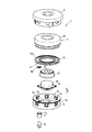
図1には、本発明にかかるエアバッグモジュール1が図2とともに示されている。このエアバッグモジュール1は、運転者用のエアバッグモジュールとされる。一方で、本発明における特徴は、別の種類のエアバッグモジュール、特に助手席乗員用のエアバッグモジュールにも適用可能とされる。
FIG. 1 shows an
エアバッグモジュール1は、ガスバッグ2(「エアバッグ」ないし「ガス袋体」ともいう)と、ガス発生器30(「ガスジェネレータ」ともいう)によって生じたガスを旋回させるべくガスバッグ2内に設けられるディフューザー21(ガス拡散用の「拡散器」ないし「散気装置」ともいう)とを備えている。
The
ディフューザー21は、キャップ状(「凸形状」ともいう)に形成されており、また当該ディフューザー21に接続される環状のフランジ22(「突縁」ともいう)を備えており、このフランジは、(例えば、ネジによる接続によって)接続解除可能となるように、又は(例えば、溶接による接続によって)接続解除不能となるようにディフューザー21に接続することができ、或いはディフューザー21と一体状に構成することができる。このため、フランジ22は、冷却液(クーラント)60を貯留する貯留部(リザーバー)として構成される。
The
ガスバッグ2と、フランジ22を備えるディフューザー21は、保護カバー40によって取り囲まれる内部空間41に配置され、またこのため、前記保護カバー40とともにガスバッグ包体4(「ガスバッグケース」ないし「ガスバッグ収容体」ともいう)を形成している。このガスバッグ包体4の内部空間41は、排気状態とされるため、ガスバッグ包体4が可能な限り小さなサイズとされる。
The
ガス発生器30は、ガスバッグ2を膨張させる機能を果たし、当該ガス発生器30は、ガスバッグ包体4のうちディフューザー21によって規定される凹み部分、即ちガスバッグ包体4の外側(外部)に配置されている。
The
ガスバッグ包体4及びガス発生器30を保持するために保持体5(「キャリア」ないし「支持体」ともいう)が設けられており、当該保持体には、所定の延在面に沿って延在し、中央部分に貫通状に形成されたガス発生器凹部51を備えた底部50が設けられており、ガス発生器30の一部が当該ガス発生器凹部から突出し、このガス発生器30は、ガス発生器30まわりのフランジ31(「突縁」ともいう)を介して、ガス発生器凹部51の範囲を規定する保持体5の底部50の端部領域52に固定されている。保持体5の壁部53は、底部50から所定の第1の方向Rに沿って突出し、運転者用のエアバッグモジュールの場合、好ましくはステアリング軸に沿って延在し、当該壁部53は、第1の方向Rと交差して延在する所定平面(底部50の延在面)に関してガス発生器30のまわりを環状に取り囲む。エアバッグモジュール1のカバー部6(「被覆部」ともいう)もまた前記壁部53に固定されており、当該カバー部6がガスバッグ包体4とその下方に配置されたガス発生器30とを被覆している。
A holding body 5 (also referred to as “carrier” or “support”) is provided to hold the
貯留部22に貯留された冷却液60を解放ないし放出するために、ガス発生器の形態の作動装置70(「駆動装置」ないし「動作発生装置」ともいう)が設けられており、当該作動装置は、シェル71によって保持体5の底部50に固定されており、前記シェル71は、第1の方向Rと交差する方向に関しガス発生器70を取り囲んでいる。好ましくは作動装置70が円柱形状とされ、その円柱軸が第1の方向Rと平行に延在する。同様に、前記シェル71が中空円筒状に構成されるのが好ましい。
In order to release or discharge the
作動装置70は保持体5に固定されており、当該作動装置70は、底部50に形成された貫通開口54を通じてエアバッグモジュール1の保持体5内へと第1の方向Rに沿ってその自由端部72が突出している。
The
底部50の貫通開口54を密閉状にシールし、また保護カバー40を保護するためにシール要素80が(必要に応じて適宜に)設けられ、当該シール要素80は、第1の方向Rと交差する方向に関し作動装置70の自由端部72を取り囲む。
In order to seal the through opening 54 of the bottom 50 in a hermetically sealed manner and to protect the
貯留部22に対するこの作動装置70の配置の詳細については、図2の断面構構造にて示されている。
The details of the arrangement of the operating
これによれば、シェル71は、このシェル71の端部領域73に、作動装置70の自由端部72のまわりに環状に形成された溝部74を備えており、保持体5の底部50のうち保持体5の貫通開口54を規定する端部55が当該溝部74に係合しており、これによりシェル71が保持体5の底部50に固定されている。更に、このシェル71は、作動装置70に対向する内面75を備えており、当該内面にも溝部76が設けられており、この溝部76に作動装置70の環状領域77が係合し、これにより作動装置70がシェル71内に強固に取り付け固定されている。
According to this, the
シェル71は、作動装置70がその自由端部72にて第1の方向Rに沿ってエアバッグモジュールの保持体5内へと突出するように寸法設定される。従って、必要に応じて適宜に設けられるシール要素80は、第1の方向Rと交差する方向に関し作動装置70の自由端部72を、閉じた環状の形態で取り囲む。
The
貯留部として構成された環状のクランプ要素(「固定要素」ないし「係止要素」ともいう)22の別の合同の貫通開口23(図1には図示されていない)が、第1の方向Rに沿って保持体5の底部50の貫通開口55に対向している。作動装置71の自由端部72をこの貫通開口23に挿入することもでき、ここでは前記別の貫通開口23の端部領域24から第1の方向Rに沿って壁部25が突出し、第1の方向Rと交差する方向に関し作動装置70の前記自由端部72のまわりを当該壁部25が環状に取り囲み、作動装置70の自由端部72が別の貫通開口23に挿入可能とされ、自由端部72を取り囲むシール要素80は、前記壁部25に対しガスバッグ包体4の保護カバー40を押圧する。そのようなシール要素80を備えていない場合には、作動装置70は、前記壁部25に対するガスバッグ包体4の保護カバー40の押圧をその自由端部72によって行うよう構成配置される。
Another joint through-opening 23 (not shown in FIG. 1) of the annular clamping element (also referred to as “fixing element” or “locking element”) 22 configured as a reservoir is in the first direction R. Along the through opening 55 of the bottom 50 of the holding
従って、シール要素80は、ガスバッグ包体4の保護カバー40を保護する機能を果たす。他方では、シール要素80は、第1の方向Rと交差して延在する環状の突出部26を備えており、当該突出部26は、第1の方向Rに関し互いに対向する2つの貫通開口54,23の端部領域の間に配置され、このようにして前記2つの貫通開口54,23をシールする。このため、クランプ要素22の別の貫通開口23が保護カバー40によって単に閉鎖される。ここで、前記保護カバー40のうち別の貫通開口23を被覆する所定の領域42は、作動装置70のうち第1の方向Rと交差して延在する前面78に対向している。
Accordingly, the sealing
前記クランプ要素22は、ガス発生器30のまわりを環状に取り囲む冷却液60用の貯留部を形成しており、前記貫通開口23を通じて貯留部22内へと所定圧力の導入が可能とされる。貯留部22内の冷却液60を押し出すために、前記貯留部22が第1の方向Rに沿って2つの部位27,28、即ち第1の部位28と第2の部位27とに区画されており、これらの部位は柔軟な薄膜の形態の可動要素90を隔てて互いに分離されており、前記薄膜90は平坦な環状で、且つ特にガス発生器30まわりを第1の方向Rと交差して環状に取り囲む構成とされる。
The
作動装置70がその自由端部72にて、例えば燃焼ガスの発生(ガス発生器)によって所定の圧力を生じた場合、これによる高温ガスは、保護カバー40のうち作動装置70の前面78に対向する領域42を破壊して、別の貫通開口23を通じて貯留部22の第1の部位28に入り込み、またその初期位置において第1の方向Rと交差して延在する薄膜90を加圧する。従って、薄膜90(可動要素)は、この初期位置では保持体5の底部50に向かう膨張部(「突出部」ともいう)を形成することができ、これにより冷却液60を収容するのに対応した容積が貯留部22の第2の部位27に形成されている。一方で、この初期位置において薄膜90が、図2に示すように所定平面に沿って平坦状に延在することもできる。
When the
前記薄膜90のうち保持体5の底部50に対向する対向面91が作動装置70によって所定の圧力(高温ガス)で加圧されると、この薄膜90は第1の方向Rに沿って保持体5の底部50から離間する方向に押圧され、これにより結果的に膨張部の向きが逆に(裏返しに)なって第1の方向Rを向く。ここで、薄膜90は、第1の方向Rに沿って冷却液60に作用し、貯留部22の流出開口100を通じガスバッグ2のうち当該ガスバッグ2によって取り囲まれた内部空間29へと冷却液60を放出する。このため、前記流出開口100は、環状の貯留部22のうちガスバッグ2の内部空間29に対向する上面22a(クランプ要素又はディフューザーの環状のフランジ)に形成されている。好ましくは、貯留部22の流出開口100は閉鎖部を備え、薄膜90を介して伝達される圧力によって当該閉鎖部が破壊(開口)される。
When the facing
冷却液60をガスバッグ2の内部空間29へと直接吐出できるようにするため、ガスバッグ2の内部空間29に前記貯留部22が配設されている。同時に、貯留部22がガスバッグ包体4のガスバッグ2をエアバッグモジュール1の保持体5に固定している。このため、ガスバッグ2のうち、ディフューザー21及び貯留部22がガスバッグ2の内部空間29へと挿入されるのを許容する流入開口の環状の端部領域2aが、保持体5の底部50と前記貯留部22との間に固定される。
The
冷却液60を放出するべく、作動装置70はセンサシステムによって任意の時点で、即ちガスバッグ2の膨張前、膨張時及び膨張後での作動が可能とされる。作動装置70のこの作動時点は、好ましくは評価用の電子機器によって算出可能とされ、即ち例えば保護乗員の体格(体重)及びガスバッグ2に対する位置のように、センサシステムで検出されるパラメータに依存するのが好ましい。作動装置70の作動時点は、リアルタイム方式による実時間での設定が可能とされる。
In order to release the
冷却液60をガスバッグ2の内部空間29へと噴射することによって、その周辺部分のガスが冷却され、これにより公知の物理法則に基づいてガスバッグ2の内部空間29の圧力はそれに応じて低下する。
By injecting the cooling
図3には、図1及び図2におけるガスバッグ包体4及び保持体5を有する本発明のエアバッグモジュールの別実施の形態が、図4から図7とともに示されている。
FIG. 3 shows another embodiment of the airbag module of the present invention having the
図1及び図2と対比すると、ガスバッグ包体4の内部空間41には冷却液60を貯留する貯留部22が設けられていないが、テザー92(「繋留帯」ないし「拘束帯」ともいう)を作動させるための機構が設けられており、このテザーは解放された無負荷の状態ではガスバッグ2の吐出開口(図示省略)を開放する構成とされる。
Compared with FIGS. 1 and 2, the
このため、既に前述した形態でガスバッグ2をエアバッグモジュール1の保持体5の底部50に固定する機能を果たすことができるディフューザー21の環状のフランジ22には、隣接する2つの貫通開口が形成されており、当該貫通開口は、テザー92用の保持要素95が成形された環状の端部領域93a,94aをそれぞれ有する第1及び第2開口93,94とされ、これにより前記保持要素95は、相対的に大きい第1開口93を閉鎖し、また第2開口94の一部は開口状態が維持される。保持要素95は可動要素90を備え、当該可動要素は、第1開口93内に配置され、また予め規定された開裂可能な環状の開裂接続部Vを介して保持要素95のフレーム96に接続されている。保持要素95は、このフレーム96を介してフランジ22に接続されるのが好ましい。
For this reason, two adjacent through openings are formed in the
前記可動要素90から第1の方向Rとは反対方向に当該可動要素90の自由端部90aが突出しており、その自由端部90aのまわりにはテザー92の自由端部に形成された環状のループ97(「環状部」ともいう)が配設されている。テザー92のうちこのループ97から離間した中央部98は、左側開口の第2開口94を通じてディフューザー21のフランジ22のうち保持体5の底部50に対向する面から、フランジ22のうちエアバッグモジュール1の保持体5の底部50とは反対側の面に延在している。
A
従って、前記テザー92は、ループ97を介してディフューザー21のフランジ22に固定されている。膨張ガスバッグ2の場合、可動要素90と可動要素90の自由端部90aまわりに配設されたループ97とによってテザー92がディフューザー21のフランジ22に固定される構成にあっては、テザー92の前記中央部98は、ガスバッグ2の吐出開口が閉鎖されるように当該吐出開口に適宜の形態で作用する。
Accordingly, the
保持要素95、特に可動要素90は、テザー92の前記ループ97が周囲に配設されたその自由端部90aが、第1の方向Rに沿って作動装置70の自由端部72の前面78と対向している。ガスバッグ包体4の保護カバー40は、結果的にはガスバッグ2の所定領域とともに第1の方向Rに沿って作動装置70と保持装置95との間に配設される。作動装置70自体がエアバッグモジュール1の保持体5の底部50の貫通開口54に配設され、図3に示すように保持体5の底部50の前記貫通開口54は、保持体5のうち底部50から第1の方向Rと反対方向に突出した領域に形成されている。作動装置70をエアバッグモジュール1の保持体5に固定するために、作動装置70のうち保持体5内へと突出する自由端部72は、保持体5の底部50の前記貫通開口54の環状の端部領域55の裏側に係合している。評価用の電子機器によってリアルタイム方式で設定可能な任意の時点(好ましくは、保護乗員の体格(体重)及びガスバッグに対する位置に依存する時点)で作動装置70が作動した場合、この作動装置70によって保護カバー40のうち第1の方向Rに沿って可動要素90に対向する領域42に高温ガスが作用し、これにより保護カバー40の前記領域42が分断され、その裏側に配置された可動要素90が所定の圧力で加圧される。このため、可動要素90と保持要素95のフレーム96(固定部分)との間の規定の開裂可能な開裂接続部Vが開裂(「破断」ともいう)し、これにより可動要素90はその初期位置を外れて移動し、ガスバッグ2の前記吐出開口を開放するべくテザー92のループ97を解放する(図6及び図7参照)。
The holding
前述のテザーによる機構の変更又は追加として、可動要素90は、その初期位置においては、エアバッグモジュール1のうちディフューザー21自体に形成された、特にはフランジ22に形成された吐出開口200を閉鎖可能とされ、第1開口93によってこの吐出開口200を形成することができる。
As a change or addition of the mechanism by the aforementioned tether, the
ここで、可動要素90は、(開裂可能な規定の開裂接続部Vの開裂時に)その初期位置を外れて移動する際に前記吐出開口200を開放する。このとき、ガスバッグ2内のガスは、ディフューザー21に形成されている吐出開口200を通じて排出可能とされ、また結果的にエアバッグモジュール1を取り囲む外側空間へと吐出可能とされる。その結果、テザー90を省略することができ、これにより単にディフューザー21に設けられた吐出開口200が可動要素90によって開放可能とされる。
Here, the
図8及び図9には、図6に示されている可動要素90の変更の実施形態が示されており、この場合にはテザー92はループ97によっては可動要素90に固定されない。
FIGS. 8 and 9 show an embodiment of a modification of the
図8によれば、可動要素90は凹部301を備えており、テザー92のうち当該テザー92の中央部98と一体状に形成された自由端部300は、形状がぴったりと適合する形態(フォームフィットの形態)でその凹部内に常時に保持され(埋設され)、これにより可動要素90は、その初期位置を外れて移動する際にテザー92の自由端部300を伴って移動する。
According to FIG. 8, the
変更例として、テザー92の自由端部300は、図9に示すように可動要素90に形成された貫通開口302に係合し、またこれにより前記貫通開口302のうち当該貫通開口302を規定する端部領域303の裏側に係合する。また、この変形例では、可動要素90は、その初期位置を外れて移動する際にテザー92の自由端部300を伴って移動する。
As a modification, the
図8及び図9における実施形態では、図6の実施形態と対比して、第1開口93のみが形成される。この第1開口93は、テザー92用の保持要素95が成形された端部領域93aを備えており、これにより保持要素95が第1開口93を閉鎖している。また、可動要素90は、第1開口93に配置されており、環状に形成された開裂可能な規定の接続部Vを介して、前記端部領域93aに成形された保持要素95のフレーム96に接続されている。勿論、第1開口93が前述のエアバッグモジュール1の吐出開口200を形成することも可能であり、これにより図8及び図9に示す実施形態の場合において、結果的にテザー92(及びガスバッグ2内に配設される吐出開口)を省略することもできる。
8 and 9, only the
特に、本発明の原理による以下の実施形態が再度説明され、実施形態の1つでは、作動装置70の自由端部72は、エアバッグモジュール1のうちガスバッグ包体4の内部空間41に配設された構成要素22の別の貫通開口23の中に或いは前方に、第1の方向Rに沿って配設される。
In particular, the following embodiment according to the principles of the present invention will be described again. In one embodiment, the
更に、保持体5の貫通開口54が前記構成要素22の別の貫通開口23と一直線上に配置されるよう構成することができる。
Furthermore, the through-opening 54 of the holding
更に、構成要素22の環状の壁部25が、別の貫通開口23を規定する端部領域24から第1の方向Rに沿って突出するよう構成することができ、前記壁部25は、作動装置70の自由端部72のまわりに第1の方向Rと交差して環状に延在し、また自由端部72は少なくとも保護カバー40が介在した状態で前記壁部25に部分的に当接する。
Furthermore, the annular wall 25 of the
更に、実施形態の1つでは、第1の方向Rと交差する所定平面にて作動装置70の自由端部72のまわりに環状に延在するシール要素80が特徴とされ、当該シール要素80が自由端部72上に位置し、また自由端部72はシール要素80及び保護カバー40が介在した状態で壁部25に部分的に当接する。
Furthermore, in one embodiment, the sealing
更に、貯留部22が、エアバッグモジュール1のディフューザー21の環状のフランジによって形成されるよう構成することができる。
Furthermore, the
更に、前記部位21をガスの拡散(分散)のためのディフューザーとして構成することができる。
Furthermore, the
更に、吐出開口200がディフューザー21内に形成されるよう構成することができる。
Further, the
更に、テザー92がそれを可動要素90に固定するためのループ97を備えるよう構成することができ、初期位置にある可動要素90を当該ループ97が取り囲む。
Further, the
更に、テザー92の自由端部300が、テザー92を可動要素90に固定するべく、形状適合によるフォームフィットの形態で可動要素90の凹部301に配設されるよう構成することができる。
Furthermore, the
更に、テザー92の自由端部300が、テザー92を可動要素90に固定するべく、可動要素90の貫通開口302内に配設されるよう構成することができ、前記自由端部300は、貫通開口302を規定する可動要素90の端部領域303の裏側に部分的に係合する。
In addition, the
本発明は、「(態様1)請求項1から3のうちのいずれか一項に記載のエアバッグモジュールであって、前記作動装置(70)は、前記可動要素(90)が前記初期位置から外れて移動するように前記可動要素(90)に圧力を作用させる構成とされ、前記作動装置(70)が特にガス発生器とされることを特徴とするエアバッグモジュール。」として構成することができる。The present invention provides the airbag module according to any one of
また、本発明は、「(態様2)請求項1から3、態様1のうちのいずれか一項に記載のエアバッグモジュールであって、前記ガスバッグ包体(4)の前記内部空間(41)は、前記ガスバッグ包体(4)を圧縮するべく排気状態とされることを特徴とするエアバッグモジュール。」として構成することができる。Further, the present invention provides the airbag module according to any one of
また、本発明は、「(態様3)請求項1から3、態様1、2のうちのいずれか一項に記載のエアバッグモジュールであって、当該エアバッグモジュール(1)は前記ガスバッグ包体(4)を保持するための保持体(5)を備え、特に前記保持体(5)上に前記作動装置(70)が配設されていることを特徴とするエアバッグモジュール。」として構成することができる。Further, the present invention provides: ((Aspect 3) The airbag module according to any one of
また、本発明は、「(態様4)態様1から3のうちのいずれか一項に記載のエアバッグモジュールであって、前記作動装置(70)は、前記保持体(5)の貫通開口(54)に配設され、これにより前記作動装置(70)のうち前記可変要素(90)に圧力を作用させる自由端部(72)が、第1の方向(R)に沿って前記貫通開口(54)外へと突出し、特に前記作動装置(70)の前記自由端部(72)が前記第1の方向(R)に沿って前記可変要素(90)に対向することを特徴とするエアバッグモジュール。」として構成することができる。Moreover, this invention is "the airbag module as described in any one of the (aspect 4) aspect 1-3, Comprising: The said action | operation apparatus (70) is a through-opening (" 54), whereby a free end (72) that applies pressure to the variable element (90) of the actuator (70) is formed in the through-opening ( 54) An airbag projecting outward, in particular, wherein the free end (72) of the actuating device (70) faces the variable element (90) along the first direction (R). Module. "
また、本発明は、「(態様5)態様4に記載のエアバッグモジュールであって、前記保護カバー(40)の領域(42)が、前記作動装置のうち前記第1の方向(R)と交差して延在する前面(78)に対向し、前記作動装置(72)が前記圧力を付与する際に前記領域(42)が破断されることを特徴とするエアバッグモジュール。」として構成することができる。Moreover, this invention is "the airbag module as described in (Aspect 5)
また、本発明は、「(態様6)態様4または5に記載のエアバッグモジュールであって、前記作動装置(70)の前記自由端部(72)は、当該エアバッグモジュール(1)のうち前記ガスバッグ包体(4)の前記内部空間(41)に配設された構成要素(22)の別の貫通開口(23)内に、或いは当該別の貫通開口の前方に前記第1の方向(R)に沿って配設されることを特徴とするエアバッグモジュール。」として構成することができる。Moreover, this invention is "the airbag module as described in (aspect 6)
また、本発明は、「(態様7)態様4から6のうちのいずれか一項に記載のエアバッグモジュールであって、前記作動装置(70)を保持するためのシェル(71)を備え、前記シェル(71)は、前記作動装置(70)を取り囲むとともに、当該エアバッグモジュール(1)の前記保持体(5)に前記作動装置(70)を固定するべく前記保持体(5)の前記貫通開口(54)の環状の端部領域(55)に固定されていることを特徴とするエアバッグモジュール。」として構成することができる。Further, the present invention provides the airbag module according to any one of (Aspect 7)
また、本発明は、「(態様8)態様3、6、態様6に従属の態様7のうちのいずれか一項に記載のエアバッグモジュールであって、前記構成要素(22)は、冷却液(60)を貯留する貯留部として、特には当該エアバッグモジュール(1)の前記保持体(5)に前記エアバッグ(2)を固定するための固定要素の形態の貯留部として構成され、特に前記可動要素(90)は、前記初期位置を外れて移動する際、前記冷却液(60)を前記ガスバッグ(2)の内部空間(29)に放出するべく前記冷却液(60)を前記構成要素(22)外へと押し出すことを特徴とするエアバッグモジュール。」として構成することができる。Further, the present invention provides the airbag module according to any one of (Aspect 8),
また、本発明は、「(態様9)請求項2、請求項2に従属の請求項3、請求項2に従属の態様1から5のうちのいずれか一項に記載のエアバッグモジュールであって、前記可動要素(90)は、その初期位置において、当該エアバッグモジュール(1)のうち前記ガスバッグ包体(4)の前記内部空間(41)に配設された部位(21)に固定されていることを特徴とするエアバッグモジュール。」として構成することができる。Further, the present invention provides an airbag module according to any one of (Aspect 9), Claim 3 dependent on
また、本発明は、「(態様10)態様9に記載のエアバッグモジュールであって、前記可動要素(90)は、規定の開裂接続部(V)を介して当該エアバッグモジュールの前記部位(21)に固定され、前記規定の開裂接続部(V)は、前記可変要素(90)がその初期位置を外れて移動する際に開裂することを特徴とするエアバッグモジュール。」として構成することができる。Further, the present invention provides the airbag module according to (Aspect 10) Aspect 9, wherein the movable element (90) is connected to the portion of the airbag module (V) via a predetermined cleavage connection (V). 21), and the prescribed cleavage connection (V) is torn when the variable element (90) moves out of its initial position. Can do.
また、本発明は、「(態様11)請求項2、請求項2に従属の請求項3、請求項2に従属の態様1から5、9、10のうちのいずれか一項に記載のエアバッグモジュールであって、前記可変要素(90)は、その初期位置で当該エアバッグモジュールの吐出開口(200)を閉鎖し、開放状態でこの吐出開口を通じて前記ガスバッグ(2)外へとガスが排出可能とされ、前記可変要素(90)は前記初期位置を外れて移動する際に前記吐出開口(200)を開放し、これにより前記吐出開口(200)を通じて前記ガスバッグ(2)外へとガスが排出されることを特徴とするエアバッグモジュール。」として構成することができる。In addition, the present invention provides: (Air according to any one of (Aspect 11)
また、本発明は、(態様12)請求項2、請求項2に従属の請求項3、請求項2に従属の態様1から5、9から11のうちのいずれか一項に記載のエアバッグモジュールであって、前記可変要素(90)は、その初期位置において当該エアバッグモジュールにテザー(92)を固定し、前記ガスバッグ(2)のうち前記テザー(92)と相互作用する吐出開口の閉鎖部が前記吐出開口を閉止し、前記可変要素(90)は、前記初期位置を外れて移動する際に前記テザー(92)を解放し、これにより前記閉鎖部が開放されることを特徴とするエアバッグモジュール。」として構成することができる。Further, the present invention relates to (Aspect 12), the airbag according to any one of
1 エアバッグモジュール
2 ガスバッグ
2a 端部領域
4 ガスバッグ包体
5 保持体
6 カバー部
21 ディフューザー
22 フランジ(クランプ要素)
22a 上面
23 貫通開口
24 端部領域
25 壁部
26 突出部
27 第1の部位
28 第2の部位
29 内部空間
30 ガス発生器
31 フランジ
40 保護カバー
41 内部空間
42 領域
50 底部
51 ガス発生器凹部
52 端部領域
53 壁部
54 貫通開口
55 端部(貫通開口)
60 冷却液
70 作動装置
71 シェル
72 自由端部
73 端部領域
74 溝部
75 内面
76 溝部
77 環状領域
78 前面
80 シール要素
90 可動要素(薄膜)
90a 自由端部
91 対向面
92 テザー
93 第1開口
93a 端部領域
94 第2開口
94a 端部領域
95 保持要素
96 フレーム
97 ループ
98 中央部
100 流出開口
200 吐出開口
300 自由端部
301 凹部
302 貫通開口
303 端部領域
DESCRIPTION OF
60
90a
Claims (6)
前記ガスバッグ包体(4)は、ガスバッグ(2)と、前記ガスバッグ(2)の状態変数に影響を及ぼす可動要素(90)と、前記ガスバッグ包体(4)の内部空間(41)を区画する気密性の保護カバー(40)とを含み、前記ガスバッグ(2)及び前記可動要素(90)が前記内部空間(41)に配設され、前記作動装置(70)は、前記状態変数に影響を及ぼすべく前記可動要素(90)を移動させる自動車用のエアバッグモジュールであって、
前記作動装置(70)は、前記ガスバッグ包体(4)の前記内部空間(41)の外側に分離して配設され、これにより前記保護カバー(40)によって、当該エアバッグモジュールのうち前記ガスバッグ包体(4)の前記内部空間(41)に配設された構成要素(2,90)と少なくとも分離されることを特徴とするエアバッグモジュール。 A gas bag envelope (4) and an actuating device (70);
The gas bag package (4) includes a gas bag (2), a movable element (90) that affects a state variable of the gas bag (2), and an internal space (41) of the gas bag package (4). And the gas bag (2) and the movable element (90) are disposed in the internal space (41), and the operating device (70) An automotive airbag module that moves the movable element (90) to affect a state variable,
The actuating device (70) is separately disposed outside the internal space (41) of the gas bag package (4), whereby the protective cover (40) allows the air bag module to An air bag module, wherein the air bag module is separated from at least the component (2, 90) disposed in the internal space (41) of the gas bag package (4).
前記作動装置(70)は、前記可動要素(90)が前記状態変数に影響を及ぼすように、前記可動要素(90)が前記状態変数に影響しない初期位置から外れるよう前記可動要素(90)を移動させることを特徴とするエアバッグモジュール。 The airbag module according to claim 1,
The actuating device (70) moves the movable element (90) out of an initial position where the movable element (90) does not affect the state variable so that the movable element (90) affects the state variable. An airbag module that is moved.
前記状態変数は前記ガスバッグ(2)内の圧力であることを特徴とするエアバッグモジュール。 The airbag module according to claim 1 or 2,
The airbag module wherein the state variables, which is a pressure within said gas bag (2).
前記ガスバッグ包体(4)の前記内部空間(41)は、前記ガスバッグ包体(4)を圧縮するべく排気状態とされることを特徴とするエアバッグモジュール。 The airbag module according to any one of claims 1 to 3 ,
The air bag module according to claim 1, wherein the internal space (41) of the gas bag package (4) is in an exhausted state so as to compress the gas bag package (4).
当該エアバッグモジュール(1)は前記ガスバッグ包体(4)を保持するための保持体(5)を備え、特に前記保持体(5)上に前記作動装置(70)が配設されていることを特徴とするエアバッグモジュール。 The airbag module according to any one of claims 1 to 4 ,
The airbag module (1) includes a holding body (5) for holding the gas bag package (4), and in particular, the operating device (70) is disposed on the holding body (5). An air bag module.
前記可動要素(90)は、前記初期位置において、当該エアバッグモジュール(1)の前記ガスバッグ包体(4)の前記内部空間(41)に配設された部位(21)に固定されていることを特徴とするエアバッグモジュール。
The airbag module according to any one of claims 2 to 5 ,
Said movable element (90), said at an initial position, is fixed to the airbag module (1) of the gas bag the envelope (4) the interior space (41) to be disposed a site (21) An air bag module.
Applications Claiming Priority (3)
| Application Number | Priority Date | Filing Date | Title |
|---|---|---|---|
| DE102008050759A DE102008050759B4 (en) | 2008-10-07 | 2008-10-07 | Airbag module for a motor vehicle |
| DE102008050759.8 | 2008-10-07 | ||
| PCT/EP2009/062681 WO2010040669A1 (en) | 2008-10-07 | 2009-09-30 | Airbag module for a motor vehicle |
Publications (3)
| Publication Number | Publication Date |
|---|---|
| JP2012505097A JP2012505097A (en) | 2012-03-01 |
| JP2012505097A5 JP2012505097A5 (en) | 2012-11-01 |
| JP5443499B2 true JP5443499B2 (en) | 2014-03-19 |
Family
ID=41393654
Family Applications (1)
| Application Number | Title | Priority Date | Filing Date |
|---|---|---|---|
| JP2011529543A Expired - Fee Related JP5443499B2 (en) | 2008-10-07 | 2009-09-30 | Airbag module for automobile |
Country Status (6)
| Country | Link |
|---|---|
| US (1) | US8109533B2 (en) |
| EP (1) | EP2334522B1 (en) |
| JP (1) | JP5443499B2 (en) |
| CN (1) | CN102123891B (en) |
| DE (1) | DE102008050759B4 (en) |
| WO (1) | WO2010040669A1 (en) |
Families Citing this family (4)
| Publication number | Priority date | Publication date | Assignee | Title |
|---|---|---|---|---|
| DE102009055266A1 (en) * | 2009-12-23 | 2011-06-30 | Takata-Petri Ag, 63743 | Airbag module for a motor vehicle |
| FR3059092B1 (en) * | 2016-11-18 | 2018-12-14 | Safran Aircraft Engines | PYROTECHNIC DEVICE |
| DE202017105555U1 (en) * | 2017-09-14 | 2018-12-17 | Dalphi Metal Espana, S.A. | Inflation protection to prevent damage when inflating a gas bag |
| JP2023090502A (en) * | 2021-12-17 | 2023-06-29 | 豊田合成株式会社 | air bag device |
Family Cites Families (19)
| Publication number | Priority date | Publication date | Assignee | Title |
|---|---|---|---|---|
| DE10114208A1 (en) | 2001-03-23 | 2002-05-08 | Trw Automotive Safety Sys Gmbh | Gasbag module assembly process involves stowing at least one component in cover, creating negative pressure in cover and closing it, making it gastight |
| US6648371B2 (en) * | 2001-07-12 | 2003-11-18 | Delphi Technologies, Inc. | Variable venting air bag assembly |
| US20030107207A1 (en) * | 2001-10-12 | 2003-06-12 | Trw Inc. | Air bag module with vent cover |
| US6773030B2 (en) | 2002-07-24 | 2004-08-10 | Trw Vehicle Safety Systems Inc. | Air bag with vent |
| US7055856B2 (en) * | 2003-02-06 | 2006-06-06 | Key Safety Systems, Inc. | Airbag module for selectively venting airbag inflation gas |
| ES2283982T3 (en) * | 2003-04-16 | 2007-11-01 | Key Safety Systems, Inc. | AIRBAG MODULE WITH CONTROLLED EVACUATION OF INFLATION GAS. |
| DE102006013359A1 (en) | 2005-06-10 | 2006-12-14 | Takata-Petri Ag | Airbag module for a motor vehicle |
| DE102005060684A1 (en) | 2005-06-10 | 2006-12-21 | Takata-Petri Ag | Airbag module for motor vehicle has second flow outlet opening connected to gas outlet opening of gas generator in such way that gas flowing from this outlet opening is directly at least partially into outer chamber |
| DE202005011878U1 (en) * | 2005-07-21 | 2005-10-13 | Takata-Petri Ag | Airbag module for motor vehicle has protective casing enclosing gas generator body with opening(s) through which ignition device protrudes out of casing and sealed gas-tight by at least one sealing element |
| DE102005039419B4 (en) * | 2005-08-16 | 2011-01-13 | Takata-Petri Ag | Occupant restraint system |
| DE202005016457U1 (en) * | 2005-10-17 | 2006-01-19 | Takata-Petri Ag | Airbag module for a motor vehicle |
| JP4877733B2 (en) * | 2005-12-28 | 2012-02-15 | タカタ株式会社 | Manufacturing method of airbag module |
| DE102006010953A1 (en) * | 2006-03-03 | 2007-09-06 | Takata-Petri Ag | Airbag module for a motor vehicle |
| JP2007261411A (en) | 2006-03-28 | 2007-10-11 | Toyoda Gosei Co Ltd | Airbag device |
| JP4898271B2 (en) * | 2006-04-18 | 2012-03-14 | タカタ株式会社 | Airbag device, vehicle, and method of manufacturing airbag device |
| JP2008137588A (en) * | 2006-12-05 | 2008-06-19 | Toyoda Gosei Co Ltd | Actuator with working pin |
| DE202007003906U1 (en) * | 2007-03-12 | 2007-07-12 | Takata-Petri Ag | Airbag arrangements for a vehicle occupant restraint system |
| JP4885035B2 (en) * | 2007-03-30 | 2012-02-29 | 日本プラスト株式会社 | Airbag device |
| JP4996550B2 (en) * | 2008-06-11 | 2012-08-08 | タカタ株式会社 | Airbag device |
-
2008
- 2008-10-07 DE DE102008050759A patent/DE102008050759B4/en not_active Expired - Fee Related
-
2009
- 2009-09-30 WO PCT/EP2009/062681 patent/WO2010040669A1/en active Application Filing
- 2009-09-30 EP EP09743882A patent/EP2334522B1/en not_active Not-in-force
- 2009-09-30 JP JP2011529543A patent/JP5443499B2/en not_active Expired - Fee Related
- 2009-09-30 CN CN2009801319670A patent/CN102123891B/en not_active Expired - Fee Related
-
2011
- 2011-01-13 US US13/006,254 patent/US8109533B2/en not_active Expired - Fee Related
Also Published As
| Publication number | Publication date |
|---|---|
| WO2010040669A1 (en) | 2010-04-15 |
| US20110109065A1 (en) | 2011-05-12 |
| JP2012505097A (en) | 2012-03-01 |
| EP2334522B1 (en) | 2012-09-05 |
| EP2334522A1 (en) | 2011-06-22 |
| CN102123891A (en) | 2011-07-13 |
| US8109533B2 (en) | 2012-02-07 |
| DE102008050759A1 (en) | 2010-04-08 |
| DE102008050759B4 (en) | 2012-04-26 |
| CN102123891B (en) | 2013-08-28 |
Similar Documents
| Publication | Publication Date | Title |
|---|---|---|
| JP4823319B2 (en) | Airbag module for vehicles | |
| JP4100129B2 (en) | Airbag device | |
| US7469926B2 (en) | Active venting inflator device | |
| US8015906B2 (en) | Actuator with actuating pin | |
| JP5443499B2 (en) | Airbag module for automobile | |
| JP2012505097A5 (en) | ||
| US7802810B2 (en) | Airbag module for a motor vehicle | |
| JP2007506611A (en) | Airbag device for vehicle | |
| US7686329B2 (en) | Airbag module for a motor vehicle | |
| JP4809504B2 (en) | Airbag module for automobile | |
| US7900959B2 (en) | Airbag apparatus | |
| JP2007315533A (en) | Stopper | |
| JP2010535663A (en) | Airbag module for vehicles | |
| JPH09175302A (en) | Air bag device | |
| JP5924217B2 (en) | Air bag device for knee protection | |
| WO2012132158A1 (en) | Air bag device | |
| US20060097498A1 (en) | Gas bag module | |
| JPH03279058A (en) | Retractor for seat belt | |
| JP4014104B2 (en) | Airbag device | |
| JP4014105B2 (en) | Airbag device | |
| JPH09272391A (en) | Cover for air bag | |
| JP4014103B2 (en) | Airbag device | |
| JP2578456Y2 (en) | Airbag device | |
| JP5020804B2 (en) | Airbag device | |
| JP2000043673A (en) | Airbag device |
Legal Events
| Date | Code | Title | Description |
|---|---|---|---|
| A521 | Written amendment |
Free format text: JAPANESE INTERMEDIATE CODE: A523 Effective date: 20120914 |
|
| A621 | Written request for application examination |
Free format text: JAPANESE INTERMEDIATE CODE: A621 Effective date: 20120914 |
|
| A977 | Report on retrieval |
Free format text: JAPANESE INTERMEDIATE CODE: A971007 Effective date: 20131115 |
|
| TRDD | Decision of grant or rejection written | ||
| A01 | Written decision to grant a patent or to grant a registration (utility model) |
Free format text: JAPANESE INTERMEDIATE CODE: A01 Effective date: 20131128 |
|
| A61 | First payment of annual fees (during grant procedure) |
Free format text: JAPANESE INTERMEDIATE CODE: A61 Effective date: 20131219 |
|
| R150 | Certificate of patent or registration of utility model |
Free format text: JAPANESE INTERMEDIATE CODE: R150 |
|
| LAPS | Cancellation because of no payment of annual fees |