EP2330505B1 - Procédé de gestion de fonctionnement de système de traitement d'informations - Google Patents
Procédé de gestion de fonctionnement de système de traitement d'informations Download PDFInfo
- Publication number
- EP2330505B1 EP2330505B1 EP09814346.4A EP09814346A EP2330505B1 EP 2330505 B1 EP2330505 B1 EP 2330505B1 EP 09814346 A EP09814346 A EP 09814346A EP 2330505 B1 EP2330505 B1 EP 2330505B1
- Authority
- EP
- European Patent Office
- Prior art keywords
- information processing
- processing device
- workload
- power
- power consumption
- Prior art date
- Legal status (The legal status is an assumption and is not a legal conclusion. Google has not performed a legal analysis and makes no representation as to the accuracy of the status listed.)
- Not-in-force
Links
- 230000010365 information processing Effects 0.000 title claims description 207
- 238000007726 management method Methods 0.000 title claims description 28
- 238000003860 storage Methods 0.000 claims description 51
- 238000012545 processing Methods 0.000 claims description 34
- 238000001816 cooling Methods 0.000 claims description 32
- 238000000034 method Methods 0.000 claims description 19
- 238000004088 simulation Methods 0.000 claims description 12
- 238000002474 experimental method Methods 0.000 claims description 2
- 238000011156 evaluation Methods 0.000 description 35
- 238000010586 diagram Methods 0.000 description 21
- 239000003795 chemical substances by application Substances 0.000 description 19
- 238000004378 air conditioning Methods 0.000 description 12
- 230000020169 heat generation Effects 0.000 description 9
- 238000012546 transfer Methods 0.000 description 9
- 238000004458 analytical method Methods 0.000 description 8
- 238000012800 visualization Methods 0.000 description 8
- 238000013500 data storage Methods 0.000 description 6
- 238000005516 engineering process Methods 0.000 description 4
- 230000006872 improvement Effects 0.000 description 4
- 238000013459 approach Methods 0.000 description 3
- 238000004364 calculation method Methods 0.000 description 3
- 230000007423 decrease Effects 0.000 description 3
- 238000005259 measurement Methods 0.000 description 3
- 238000005457 optimization Methods 0.000 description 3
- CURLTUGMZLYLDI-UHFFFAOYSA-N Carbon dioxide Chemical compound O=C=O CURLTUGMZLYLDI-UHFFFAOYSA-N 0.000 description 2
- 238000004891 communication Methods 0.000 description 2
- 238000012790 confirmation Methods 0.000 description 2
- 238000007596 consolidation process Methods 0.000 description 2
- 238000000605 extraction Methods 0.000 description 2
- 230000006870 function Effects 0.000 description 2
- 238000012544 monitoring process Methods 0.000 description 2
- 230000008569 process Effects 0.000 description 2
- 238000009825 accumulation Methods 0.000 description 1
- 238000003491 array Methods 0.000 description 1
- 229910002092 carbon dioxide Inorganic materials 0.000 description 1
- 239000001569 carbon dioxide Substances 0.000 description 1
- 230000015556 catabolic process Effects 0.000 description 1
- 238000010276 construction Methods 0.000 description 1
- 238000006731 degradation reaction Methods 0.000 description 1
- 230000003111 delayed effect Effects 0.000 description 1
- 238000013461 design Methods 0.000 description 1
- 238000011161 development Methods 0.000 description 1
- 238000009792 diffusion process Methods 0.000 description 1
- 230000000694 effects Effects 0.000 description 1
- 230000004927 fusion Effects 0.000 description 1
- 239000007788 liquid Substances 0.000 description 1
- 230000014759 maintenance of location Effects 0.000 description 1
- 230000002265 prevention Effects 0.000 description 1
- 230000009467 reduction Effects 0.000 description 1
- 230000004044 response Effects 0.000 description 1
- 238000010792 warming Methods 0.000 description 1
Images


Classifications
-
- G—PHYSICS
- G06—COMPUTING; CALCULATING OR COUNTING
- G06F—ELECTRIC DIGITAL DATA PROCESSING
- G06F1/00—Details not covered by groups G06F3/00 - G06F13/00 and G06F21/00
- G06F1/16—Constructional details or arrangements
- G06F1/20—Cooling means
- G06F1/206—Cooling means comprising thermal management
-
- G—PHYSICS
- G06—COMPUTING; CALCULATING OR COUNTING
- G06F—ELECTRIC DIGITAL DATA PROCESSING
- G06F1/00—Details not covered by groups G06F3/00 - G06F13/00 and G06F21/00
- G06F1/26—Power supply means, e.g. regulation thereof
- G06F1/32—Means for saving power
- G06F1/3203—Power management, i.e. event-based initiation of a power-saving mode
-
- G—PHYSICS
- G06—COMPUTING; CALCULATING OR COUNTING
- G06F—ELECTRIC DIGITAL DATA PROCESSING
- G06F9/00—Arrangements for program control, e.g. control units
- G06F9/06—Arrangements for program control, e.g. control units using stored programs, i.e. using an internal store of processing equipment to receive or retain programs
- G06F9/46—Multiprogramming arrangements
- G06F9/50—Allocation of resources, e.g. of the central processing unit [CPU]
- G06F9/5005—Allocation of resources, e.g. of the central processing unit [CPU] to service a request
- G06F9/5027—Allocation of resources, e.g. of the central processing unit [CPU] to service a request the resource being a machine, e.g. CPUs, Servers, Terminals
-
- G—PHYSICS
- G06—COMPUTING; CALCULATING OR COUNTING
- G06F—ELECTRIC DIGITAL DATA PROCESSING
- G06F9/00—Arrangements for program control, e.g. control units
- G06F9/06—Arrangements for program control, e.g. control units using stored programs, i.e. using an internal store of processing equipment to receive or retain programs
- G06F9/46—Multiprogramming arrangements
- G06F9/50—Allocation of resources, e.g. of the central processing unit [CPU]
- G06F9/5094—Allocation of resources, e.g. of the central processing unit [CPU] where the allocation takes into account power or heat criteria
-
- Y—GENERAL TAGGING OF NEW TECHNOLOGICAL DEVELOPMENTS; GENERAL TAGGING OF CROSS-SECTIONAL TECHNOLOGIES SPANNING OVER SEVERAL SECTIONS OF THE IPC; TECHNICAL SUBJECTS COVERED BY FORMER USPC CROSS-REFERENCE ART COLLECTIONS [XRACs] AND DIGESTS
- Y02—TECHNOLOGIES OR APPLICATIONS FOR MITIGATION OR ADAPTATION AGAINST CLIMATE CHANGE
- Y02D—CLIMATE CHANGE MITIGATION TECHNOLOGIES IN INFORMATION AND COMMUNICATION TECHNOLOGIES [ICT], I.E. INFORMATION AND COMMUNICATION TECHNOLOGIES AIMING AT THE REDUCTION OF THEIR OWN ENERGY USE
- Y02D10/00—Energy efficient computing, e.g. low power processors, power management or thermal management
Definitions
- the present invention relates to an operation management method of an information processing system including a group of information processing devices such as server devices, storage devices and network devices and cooling equipment for cooling the devices, and more particularly to workload allocation to the group of information processing devices, which is required to achieve the integrative power saving operation of the group of information processing devices and the cooling equipment.
- a group of information processing devices such as server devices, storage devices and network devices and cooling equipment for cooling the devices
- Respective approaches for the power saving of the data center have been started in information processing devices such as server devices, storage devices and network devices, cooling equipment, and operation management.
- information processing device the improvement in performance per power consumption by means of a low-power device and the employment of the power saving function by the switching of operating states in accordance with workload have been promoted.
- cooling equipment the operational efficiency improvement of an air conditioner itself, the optimization of an airflow design of an inlet and an outlet and the introduction of local cooling and liquid cooling have been started.
- the operation management the operation information monitoring, the job scheduling and the operational efficiency improvement or consolidation of a device group by means of virtualization have been adopted as main measures.
- the cooling equipment is generally designed based on the maximum rated power of the device group, the power consumption of the cooling equipment during operation depends heavily on distribution and fluctuation of the power of the device group with respect to the cooling equipment. For example, since the efficiency of the air conditioner depends on the power or heat generation of the device, a position relationship and a distance between the air conditioner and the device, a temperature, an air volume, an airflow direction and the like, the cooling power is heavily influenced by the power and the arrangement of the device.
- Patent Document 1 in a management server for performing the job scheduling to parallel computers, a new job is input into a low-temperature computer based on temperature sensor information of the computers, and a job is transferred from a high-temperature computer to a low-temperature computer, thereby preventing the failure and the performance degradation in the parallel computers due to high temperature. Furthermore, whether to transfer a job is determined by estimating the power consumption of each computer and cooling equipment provided for each computer before and after the job transfer based on temperature information.
- Patent Document 2 in a management system for a plurality of computers, an overheated computer and a non-overheated computer are extracted based on temperature distribution and operation information of the computers, and software is transferred from the former to the latter, thereby achieving the power saving. Furthermore, after the extraction of target computers, fluctuations in computer power and air conditioner power before and after the transfer of the software are compared, thereby determining whether to transfer the software.
- the computer power is obtained from the operation information
- the air conditioner power is obtained from the temperature distribution
- the temperature distribution is obtained from temperature sensors, a temperature history and the operation information.
- Patent Document 3 in a method of allocating workloads to a plurality of servers in a data center, a requested workload profile is compared with a historical profile, and the requested workload is allocated to a server in accordance with a history that minimizes the power of the server and an air conditioner, or randomly allocated if there is no matching history.
- the historical profile includes server location, class, operation information, inlet temperature, outlet temperature, workload type and power of the server and air conditioner.
- the power of the server and air conditioner is obtained from the inlet and outlet temperatures of the server, specific heat and air volume or measured by a power meter.
- Patent Document 4 in a method of distributing power to a plurality of servers in a data center, power budgets are lent and borrowed between the servers or racks that are close in geographic location so as to approach to an ideal and analog temperature distribution or power distribution, and a discretized power state of the server is assigned based on the budget distribution, thereby preventing the failure of the servers due to a hot spot or a cold spot.
- a thermal multiplier indicating ideal power for each server is obtained from an outlet temperature of each server, a reference outlet temperature of an average server and a supply air temperature of air conditioner.
- Patent Document 1 a job is allocated to a low-temperature computer of parallel computers, but this does not always contribute to power saving. Furthermore, since the power consumptions of the computers before and after the transfer of a job are estimated, although power associated with a transfer source and a transfer destination decreases, this is only local power saving for the whole of the parallel computers. More specifically, this does not lead to comprehensive power saving of a computer room. In Patent Document 2, fluctuations in computer power and air conditioning power before and after the transfer of software are compared with each other, but objects to be compared are limited to the extracted overheated and non-heated computers, and the total power of the computer group and the air conditioning equipment is not considered. More specifically, this does not lead to comprehensive power saving of the computer room.
- Patent Document 3 since workload is allocated to a server based on the historical profile that minimizes the power of the server and air conditioner, the total power of a server group and the air conditioning equipment can be reduced for the workload within a range of the history, but in the case of workload having no history, the improvement is conducted only sequentially according to the accumulation of history. More specifically, it necessarily takes a long time before the achievement of power saving of the computer room.
- Patent Document 4 since power budgets are lent and borrowed between servers close to each other so as to approach to an ideal temperature distribution, this does not mean that a total power of the server group is reduced. More specifically, this does not lead to comprehensive power saving of the computer room.
- the conventional technologies have the problem that only local power saving can be achieved and it takes a long time before the achievement of power saving.
- An object of the present invention is to achieve power saving in a computer room including information processing devices and air conditioners in a short time by means of the optimization of workload allocation to the information processing devices.
- the present invention has the features defined in claim 1 in order to achieve power saving in a computer room including information processing devices and air conditioners by means of the optimization of workload allocation.
- a feature of a representative embodiment is to calculate a coefficient of performance of the air conditioner with respect to an information processing device.
- a coefficient of performance COP of an air conditioner is a heat-transfer efficiency of an air conditioner when the air conditioner is operated to exchange the heat in a computer room, and it is represented by the Formula 1.
- COP heat exchange capability / air conditioner power
- the coefficient of performance of an air conditioner with respect to an information processing device is a COP when an air conditioner exchanges the heat generation of a specific information processing device, and here it is referred to as a device-specific COP.
- a COPji that is a device-specific COP of an air conditioner j with respect to an information processing device i is represented by the Formula 2 by using a heat generation amount PDi of the information processing device i and an air conditioner power PCji of the air conditioner j with respect to the information processing device i.
- COPji PDi / PCji
- the device-specific COP lowers as a distance between the air conditioner and the information processing device increases. Given that heat diffusion depends on airflow, air volume and temperature, it is necessary to obtain the device-specific COP from a result of three-dimensional thermofluid simulation or the like. However, the device-specific COP may be obtained in another way.
- the COPji that is the device-specific COP of the air conditioner j with respect to the information processing device i can be represented by the Formula 3 by using a distance Lj i between the air conditioner j and the information processing device i, a coefficient of performance COPj that is specific to the air conditioner j and an environment constant A.
- the coefficient of performance COPj of an air conditioner can be obtained from the specification of the air conditioner j, and the distance Lji can be obtained from arrangement information including locations of the air conditioners and a group of the information processing devices in the computer room.
- COPji A / Lji 2 ⁇ COPj
- an air conditioner power with respect to a certain information processing device can be calculated.
- an air conditioner power PCji of the air conditioner j with respect to the information processing device i can be represented by the Formula 4 by using a device power PDi of the information processing device i and the COPji.
- an air conditioner power PCi with respect to the information processing device i can be represented by the Formula 5 by using the number of air conditioners N, the PDi, and the COPji.
- PCji PDi / COPji [Formula 5]
- PCi ⁇ j PDi / COPji / N
- a device-associated power consumption expression Pi (x) of the information processing device i can be represented by the Formula 6 by using a device power expression PDi(x) of the information processing device i and an air conditioner power PCi (x) with respect to the information processing device i.
- Pi x PDi x + PCi x
- PDi(x) and PCi(x) are functions of a resource utilization ratio x of an information processing device.
- the resource utilization ratio is mainly a CPU utilization ratio and a memory utilization ratio.
- the resource utilization ratio is mainly a disk region utilization ratio.
- the Pi(x) represents a total of device power and air conditioner power, and position information of the air conditioner and the group of information processing devices in the computer room is taken into account for the air conditioner power. More specifically, by using the Pi(x), the evaluation of power consumption with taking the position information in the computer room into account is possible without thinking of the position information in the computer room.
- Still another feature is to calculate power consumption of the entire computer room by device-associated power consumption expression of each information processing device. Since the device-associated power consumption expression Pi(x) of the information processing device i includes device power and air conditioner power with respect to the device, it is possible to obtain power consumption of the entire computer room by totalizing the device-associated power consumption expression Pi(x) of each information processing device in the computer room.
- Still another feature is to determine workload allocation so as to achieve power saving of the entire computer room by using a power saving performance evaluation index based on the device-associated power consumption expression of an information processing device.
- a workload in a server device includes an operation of an application or a virtual OS, response to a client to be connected and the like.
- a workload of a storage device is a disk storage region or the like.
- a workload of a network device is a network throughput or the like.
- the power saving performance evaluation index is defined as processing performance per power consumption when the resource utilization ratio of the information processing device is at a resource utilization ratio maximum value.
- the processing performance in a server device is a performance value of a benchmark such as SPEC or the number of transactions per unit time.
- the processing performance in a storage device is, for example, a disk storage region.
- the resource utilization ratio maximum value is a maximum value of resource utilization ratio of a corresponding information processing device, and an administrator determines the resource utilization ratio maximum value based on a use policy of the corresponding information processing device.
- a power saving performance evaluation index EEi with respect to the information processing device i can be represented by the Formula 8 by using a resource utilization ratio maximum value Xi and a processing performance maximum value Wi of the information processing device i.
- EEi Xi ⁇ Wi / Pi Xi
- EEi is a constant, and a larger constant value indicates better performance-to-power consumption characteristics of the information processing device i.
- the power consumption shown here is a total value of the device power and the air conditioner power with respect to the information processing device i. More specifically, by allocating workload preferentially to the information processing device i having a large power saving performance evaluation index EEi, workload allocation that minimizes the power consumption of the entire computer room is possible. When workload allocation is performed according to this policy, there appears a bipolar phenomenon in which the resource utilization ratio of an information processing device having a large power saving performance evaluation index comes closer to a maximum resource utilization ratio while the resource utilization ratio of an information processing device having a small power saving performance evaluation index comes closer to zero.
- the power saving performance evaluation index EEi evaluates the power saving performance when the resource utilization ratio of an information processing device is at the resource utilization ratio maximum value with taking the bipolar phenomenon into account.
- Still another feature is to control a workload operated in each information processing device based on a result of workload allocation.
- a group of information processing devices has a workload control agent, and the workload control agent controls a workload operated in the information processing device in accordance with the result of workload allocation.
- Still another feature is to calculate an air conditioner power from the device-specific COP and a measured device power value of an information processing device.
- an air conditioner power PCj of the air conditioner j can be represented by the Formula 9 by using the number of air conditioners N, the measured device power value PDi of the information processing device i and the COPji.
- PCj ⁇ i PDi / COPji / N
- Still another feature is to control an output of each air conditioner based on a result of the above-described air conditioner power calculation.
- the air conditioner has an output control agent, and the output control agent controls the output of the air conditioner based on an instruction of an operation management device.
- FIG. 1 is a block diagram of a first embodiment of the present invention.
- an information processing device is a server device
- the workload allocation to server devices capable of saving the power in an entire computer room is achieved.
- this embodiment shows a case where two server devices are provided as information processing devices, the number of server devices may be any number.
- a storage device or a network device may coexist with the server device.
- an operation management device 100 and server devices 110a and 110b are connected to each other via a network 120.
- workloads 111a to 111d correspond to an OS on a virtual machine and an application for a web server, a DB server or the like.
- Workload allocating agents 112a and 112b receive instructions from the operation management device 100 and control the workloads 111a to 111d on the server devices 110a and 110b.
- the workload allocating agents may be provided in the server devices 110a and 110b as shown in FIG. 1 or may be disposed outside the server devices 110a and 110b.
- the workload allocating agent is a virtual OS manager, and it is provided in the server device.
- the workload allocating agent is a load balancer, and it is disposed outside the server device.
- the operation management device 100 is provided with arrangement information 200, an information processing device specification table 300, an air conditioner specification table 400, a workload specification table 600, a workload allocation table 500, a workload allocating unit 101 and a workload control unit 102. These components may be arranged within the single operation management device 100 as shown in FIG. 1 or may be arranged in a plurality of devices in a distributed manner.
- FIG. 2 shows an example of arrangement of devices in a computer room.
- the above-described arrangement information 200 set in the operation management device 100 has to include device IDs 221a and 221b of the server devices 220a and 220b, air conditioner IDs 211a and 211b of the air conditioners associated with operational environments of the respective server devices, and pieces of relative distance information 230a to 230c between the server devices and the air conditioners 210a and 210b.
- the arrangement information 200 may be in a graphic form as shown in FIG. 2 or may be in a table form.
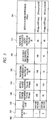
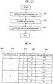
- the information processing device specification table 300 shown in FIG. 3 holds a device type 320, a device power minimum value PDmini 330, a device power maximum value PDmaxi 340, a processing performance maximum value Wi 350, an allocable processing performance 360, a resource utilization ratio maximum value Xi 370 and a device power expression PDi (x) 380 for each device ID 310 with respect to the information processing devices in the computer room.
- the device ID 310 is an identifier for identifying the information processing devices 220a and 220b in the computer room.
- the device type 320 is a piece of information for identifying types of the information processing devices.
- the device power minimum value PDmini 330 and the device power maximum value PDmaxi 340 are an idle-state device power and a maximum rated power of the information processing device, respectively.
- the device power minimum value PDmini 330 and the device power maximum value PDmaxi 340 are values specific to each information processing device and are specified in a catalogue or the like.
- an increase amount of the device power of the information processing device is assumed to be proportional to the resource utilization ratio, and the device power expression PDi(x) of an information processing device i is represented by the Formula 10 by using PDmini, PDmaxi and a resource utilization ratio x.
- the device power expression PDi(x) may be a constant for simplification or may be represented by an expression different from the Formula 10, which obtained by approximating a measured result of power consumption of the information processing device.
- PDi x PDmini + PDmaxi ⁇ PDmini ⁇ X / 100
- the processing performance maximum value Wi 350 in a server device is a maximum value of arithmetic processing performance of the server device, and a performance value of a benchmark such as SPEC or the maximum value of the number of transactions per unit time of a certain application is used.
- the allocable processing performance 360 is processing performance to which workload can be allocated, and it is equal to the processing performance maximum value Wi when no workload is allocated.
- the resource utilization ratio maximum value Xi 370 in the server device is an allocation maximum value of CPU utilization ratio and a memory utilization ratio of the server device, and it is set by an administrator according to a use policy of the server device. For example, when power saving performance is given priority, the resource utilization ratio maximum value is set high so that more workloads are consolidated in the server device. On the other hand, when service continuity is given priority, the resource utilization ratio maximum value is set low so that a workload is allocated with room left in the resource of the server device.
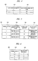
- the air conditioner specification table 400 shown in FIG. 4 holds an air conditioner COP 420 for each air conditioner ID 410 with respect to the air conditioners in the computer room.
- the air conditioner ID 410 is an identifier for identifying the air conditioners 210a and 210b in the computer room.
- the air conditioner COP 420 is specified in a catalogue or the like.
- the workload specification table 500 shown in FIG. 5 holds an allocation target device type 520, a workload amount 530 and an allocation policy 540 for each workload ID 510 with respect to the workloads.
- the workload ID 510 is a piece of information for identifying workloads executed in the computer room.
- the allocation target device type 520 is a piece of information showing a type of information processing device to which a corresponding workload can be allocated.
- the workload amount 530 in the server device is an expected value of arithmetic processing performance of the server device that is required for the operation of a corresponding workload, and it is represented by using the same reference as the processing performance maximum value 350.
- the allocation policy 540 is a piece of information referred to when the workload allocating unit 101 determines workload allocation. In FIG. 5 , service priority and power saving priority are specified as allocation policies, but another allocation policy may be used or no allocation policy may be used.
- the workload allocation table 600 shown in FIG. 6 is a table showing a relationship between each workload and the information processing device to which the workload is allocated.
- the workload is identified by using a workload ID 610, and the information processing device of an allocation destination is identified by an allocated device ID 620.
- FIG. 7 shows a processing flow in the workload allocating unit.
- This processing flow includes a device-specific COP calculating step 701, a device-associated power consumption expression creating step 702, a device evaluation index calculating step 703, an allocable information processing device extracting step 704 and a workload allocating step 705, in which the arrangement information 200, the information processing device specification table 300, the air conditioner specification table 400 and the workload specification table 500 are taken as inputs and the workload allocation table 600 is output.
- the allocable information processing device extracting step 704 and the workload allocating step 705 are processes performed to all workloads, and are performed for each workload.
- the arrangement information 200 is taken as an input and an output result 900 shown in FIG. 9 is output.
- the output result 900 holds a distance 930 from each information processing device and a device-specific COP 940 of each information processing device with respect to each air conditioner.
- the air conditioners are identified by air conditioner IDs 910, and the information processing devices are identified by device IDs 920.
- a distance Lji 930 between an air conditioner j and an information processing device i is calculated by analyzing the arrangement information 200. Calculation of a COPji 940 that is a device-specific COP uses the Formula 3.
- the environment constant A in the Formula 3 is set so that an average of the COPji of the air conditioners j becomes a COPj.
- the device-specific COP or the environment constant A may be obtained by an experiment in the computer room or may be obtained based on a three-dimensional thermofluid simulation.
- an air conditioner power with respect to a device power can be obtained by using a three-dimensional thermofluid simulation or a high-speed simulation engine in which main parameters are extracted based on a three-dimensional thermofluid simulation, and a device-specific COP can be calculated from the air conditioner power.
- a device temperature can be obtained from the device power when these simulations are used.
- FIG. 10 shows an output result 1000 of the device-associated power consumption expression creating step 702.
- the output result 1000 holds a device-associated power consumption expression 1020 for each device ID 1010.
- the device-associated power consumption expression 1020 is calculated by utilizing the Formula 4, the Formula 5 and the Formula 6.
- FIG. 11 shows an output result 1100 at the device evaluation index calculating step 703.
- a power saving performance evaluation index EEi 1120 and a service continuity evaluation index ESi 1130 are used as evaluation indexes of each information processing device.
- the power saving performance evaluation index EEi 1120 is a constant calculated based on the Formula 8, and it indicates the performance per associated power consumption in the maximum resource utilization ratio of the information processing device i.
- EEi is a power saving performance evaluation index taking into account the air conditioner power and the arrangement information of the computer room
- workload allocation capable of reducing the power consumption of the entire computer room can be determined by allocating workloads to the server devices in descending order of EEi values.
- the service continuity evaluation index ESi 1130 is a constant calculated based on the Formula 11, and it indicates an available resource amount of an information processing device in maximum resource utilization ratio of the information processing device i. Workload allocation having room left in the information processing devices can be determined by allocating workloads to the server devices in descending order of ESi values.
- the two evaluation indexes EEi and ESi with respect to each information processing device are used, but only the power saving performance evaluation index EEi may be used or another evaluation index may be used.
- ESi Wi ⁇ 100 ⁇ Xi / 100
- the workload specification table 500 and the information processing device specification table 300 are taken as inputs, and an information processing device to which a workload can be allocated is extracted. Specifically, an information processing device whose device type 320 is identical to the allocation target device type 520 and whose allocable processing performance 360 is larger than the workload amount 530 is extracted with reference to the allocation target device type 520 and the workload amount 530 of the workload, and the device type 320 and the allocable processing performance 360 of the information processing device.
- the information processing device includes a resource required to be secured in the workload allocation in addition to the allocable processing performance 360.
- the resource corresponds to a disk storage region, the number of licenses of an OS or application or the like, and when the information processing device is a storage device, the resource corresponds to the number of connected clients.
- These resources do not appear in the Formula 8 and the Formula 11, but are factors in determining whether to perform allocation.
- the processing is shown based on an assumption that these resources are sufficiently secured, but the workload specification table 500 or the information processing device specification table 300 may hold the information of these resources so that the information can be used as a restriction condition in the extraction of the information processing device.
- the information processing device to be an allocation destination of the workload is determined in accordance with the allocation policy from the information processing device extracted at the allocable information processing device extracting step 704 and the output result 1100 at the device evaluation index calculating step.
- FIG. 6 shows the workload allocation table 600 that is an output result of the workload allocating step 705.
- the workload allocating step 705 when the allocation policy is power saving priority, an information processing device having the highest power saving performance evaluation index EEi is determined as the information processing device to be the allocation destination of the workload, and when the allocation policy is service priority, an information processing device having the highest service continuity evaluation index ESi is determined as the information processing device to be the allocation destination of the workload.
- the workload amount 530 of the workload is subtracted from a value of the allocable processing performance 360 of the corresponding information processing device.
- the device-specific COP calculating step 701 to the workload allocating step 705 may be repeated until a convergence condition is satisfied like the processing flow shown in FIG. 8 .
- a device-specific COP is obtained by a three-dimensional thermofluid simulation
- a sequence of processes of obtaining device power distribution that is input information of the three-dimensional thermofluid simulation at the workload allocating step 705 and calculating a device-specific COP based on the obtained distribution at the device-specific COP calculating step 701 is repeated until the convergence condition is satisfied.
- the convergence condition at a convergence condition determination 801 is that a difference in device-specific COP from the last calculation result is within a threshold, a result of workload allocation is equal to the last workload allocation result and the like. Furthermore, a restriction condition that a device temperature obtained by a three-dimensional thermofluid simulation or a high-speed simulation engine does not exceed an operational upper limit temperature of the information processing device or a temperature obtained by subtracting a margin from the operational upper limit temperature may be added in the workload allocating step 705.
- the flow of the workload allocating unit shown in FIG. 8 is also applicable to the case where the amount of heat generation of an information processing device is influenced by heat generated from an adjacent information processing device, the case where the device power of the information processing device is influenced by the temperature in the computer room and the like.
- the workload control unit 102 uses the workload allocation table 600 to control the workloads 111a to 111d of the information processing devices 110a and 110b. This control varies depending on the types of the information processing devices.
- the workload control unit 102 changes settings of a virtual OS manager and a workload balancer corresponding to the workload allocating agents 112a and 112b, and allocates workloads to the server devices based on the workload allocation table 600.
- the workload allocation capable of saving the power of the computer room can be achieved by determining an optimum allocation of workloads to the server devices with taking into account the air conditioner power and controlling the workloads on the server devices in accordance with the allocation.
- FIG. 12 is a diagram showing a second embodiment of the present invention.
- the information processing device when the information processing device is a storage device, the workload allocation capable of saving the power in the entire computer room can be achieved.
- this embodiment shows a case where two storage devices are provided as information processing devices, the number of storage devices may be any number.
- a server device or a network device may coexist with the storage device.
- an operation management device 1200, storage devices 1210a and 1210b and a workload allocating agent 1220 are connected to each other via the network 120.
- workloads 1211a to 1211d are data storage regions.
- the workload allocating agent 1220 receives instructions from the operation management device and controls the data storage regions of the storage devices.
- the workload allocating agent 1220 for the storage devices is a storage manager and is generally disposed outside the storage devices.
- the operation management device 1200 shown in FIG. 12 is provided with arrangement information 1300, an information processing device specification table 1400, the air conditioner specification table 400, a workload specification table 1500, a workload allocation table 1900, a workload allocating unit 1201 and a workload control unit 1202.
- arrangement information 1300, the information processing device specification table 1400, the workload specification table 1500, the workload allocating unit 1201 and the workload control unit 1202 which are differences from the first embodiment will be described.
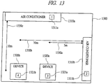
- the arrangement information 1300 shown in FIG. 13 is a piece of information showing position relationships between air conditioners 1310a and 1310b and storage devices 1320a and 1320b in the computer room.
- Air conditioner IDs 1311a and 1311b are assigned to the air conditioners 1310a and 1310b, respectively, and device IDs 1321a and 1321b are assigned to the storage devices 1320a and 1320b, respectively.
- the arrangement information includes pieces of relative distance information 1330a to 1330c between the air conditioners 1310a and 1310b and the storage devices 1320a and 1320b.
- the arrangement information may be in a graphic form shown in FIG. 13 or may be in a table form as long as the relative distances between the air conditioners and the storage devices can be understood.
- the information processing device specification table 1400 shown in FIG. 14 holds a device type 1420, a device power minimum value PDmini 1430, a device power maximum value PDmaxi 1440, a processing performance maximum value Wi 1450, an allocable processing performance 1460, a resource utilization ratio maximum value Xi 1470 and a device power expression 1480 for each device ID 1410 with respect to the storage devices in the computer room.
- the processing performance maximum value Wi 1450 is a maximum value of a data storage region of the storage device, and it is specified in a catalogue or the like.
- the resource utilization ratio maximum value Xi 1470 is a maximum value of utilization ratio of the data storage region of the storage device, and it is referred to by the workload allocating unit 1201 in the workload allocation.
- the workload specification table 1500 shown in FIG. 15 holds an allocation target device type 1520 and a workload amount 1530 for each workload ID 1510 with respect to the workloads.
- the workload amount 1530 in the storage device is a size of the data storage region required by a corresponding workload.
- an allocation policy is not specified, but an allocation policy may be specified like in the workload specification table 500 of the first embodiment.
- a processing flow of the workload allocating unit 1201 in this embodiment is the same as the processing flow 700 of the workload allocating unit of the first embodiment.
- the arrangement information 1300 and the air conditioner specification table 400 are taken as inputs, and a device-specific COP for each air conditioner shown in an output result 1600 is output.
- the information processing device specification table 1400 and the output result 1600 of the device-specific COP calculating step are taken as inputs, and a device-associated power consumption expression of each information processing device shown in an output result 1700 is output.
- the device power of the storage device is assumed to be constant regardless of the resource utilization ratio, and a device-associated power consumption expression Pi(x) is obtained by fixing the device power expression PDi (x) of the storage device at the device power maximum value PDmaxi.
- the device power expression PDi(x) and the device-associated power consumption expression Pi(x) may be obtained so that the device power increases or decreases in accordance with the resource utilization ratio.
- the device-associated power consumption expression 1700 and the information processing device specification table 1400 are taken as inputs, and an evaluation index for each storage device shown in an output result 1800 is output.
- an evaluation index for each storage device shown in an output result 1800 is output.
- only the power saving performance evaluation index EEi is output.
- other evaluation indexes may be output as described in the first embodiment.
- the evaluation index 1800 for each information processing device, the workload specification table 1500 and the information processing device specification table 1400 are taken as inputs, and the workload allocation table 1900 shown in FIG. 19 is output.
- the power saving performance evaluation index EEi of the storage device 1320a whose device ID is 3 is higher than that of the storage device 1320b whose device ID is 4, and therefore, workloads with respect to the storage devices are intensively allocated to the storage device 1320a in the workload allocation table 1900. This indicates that the power of the computer room including the air conditioner power can be saved by the intensive allocation of workloads to the storage device 1320a.
- the workload control unit 1202 controls a workload of each of the information processing devices 1210a and 1210b by using the workload allocation table 1900. This control varies depending on the types of the information processing devices.
- the workload control unit changes settings of the storage manager corresponding to the workload allocating agent 1220, and allocates a data storage region that is a workload of each storage device based on the workload allocation table 1900.
- the workload allocation capable of saving the power of the computer room can be achieved by determining an optimum allocation of workloads to the storage devices with taking into account the air conditioner power and controlling the workloads on the storage devices in accordance with the allocation.
- FIG. 20 is a diagram showing a third embodiment of the present invention.
- an air conditioner power required for cooling information processing devices 2010a to 2010d in a computer room is obtained, and air conditioners 2020a and 2020b are controlled in accordance with the obtained air conditioner power, thereby saving the power of an entire computer room.
- this embodiment shows a case where four information processing devices and two air conditioners are provided, the numbers of information processing devices and air conditioners may be any number.
- This embodiment may be implemented in parallel with the first embodiment and the second embodiment or may be performed independently.
- an operation management device 2000, the information processing devices 2010a to 2010d, the air conditioners 2020a and 2020b are connected to each other via the network 120.
- the information processing devices 2010a to 2010d in the computer room are provided with power measuring agents 2011a to 2011d.
- the power measuring agents 2011a to 2011d measure the device power of the information processing devices and transmit the results of the measurements to the operation management device 2000.
- the air conditioners 2020a and 2020b are provided with output control agents 2021a and 2021b.
- the output control agents 2021a and 2021b control outputs of the air conditioners 2020a and 2020b in accordance with requests from the operation management device 2000.
- the operation management device 2000 is provided with arrangement information 2100, the air conditioner specification table 400, an air conditioner power table 2200, an air conditioner power calculating unit 2001 and an air conditioner control unit 2002.
- the arrangement information 2100 shown in FIG. 21 is a piece of information showing position relationships between air conditioners 2110a and 2110b and information processing devices 2120a to 2120d in the computer room.
- Air conditioner IDs 2111a and 2111b are assigned to the air conditioners 2110a and 2110b, respectively, and device IDs 2121a to 2121d are assigned to the information processing devices 2120a to 2120d, respectively.
- the arrangement information 2100 includes pieces of information 2130a to 2130d on relative distances between the air conditioners 2110a and 2110b and the information processing devices 2120a to 2120d.
- the arrangement information may be in a graphic form as shown in FIG. 21 or may be in a table form as long as the relative distances between the air conditioners and the information processing devices can be understood.
- the air conditioner power table 2200 shown in FIG. 22 holds an optimum air conditioner power 2250 for each of the air conditioner IDs 2210 of the air conditioners.
- the air conditioner power 2250 is calculated from a device power measured value 2230 and an air conditioner power expression 2240 for each of the device IDs 2220 of the information processing devices.
- the air conditioner power table 2200 is created by the air conditioner power calculating unit 2001, and it is referred to when the air conditioner control unit 2002 controls the outputs of the air conditioners 2110a and 2110b.
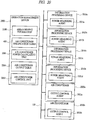
- FIG. 23 shows a processing flow of the air conditioner power calculating unit 2001.
- This processing flow includes a device-specific COP calculating step 2301, a device power acquiring step 2302 and an air conditioner power calculating step 2303, in which the arrangement information 2100, the air conditioner specification table 400 and the device power measured value 2230 of the information processing device are taken as inputs and the air conditioner power table 2200 is output.
- the device-specific COP calculating step 2301 is the same as the device-specific COP calculating step 701 in the first embodiment.
- the arrangement information 2100 and the air conditioner specification table 400 are taken as inputs and a device-specific COP is output.
- FIG. 24 shows an output result 2400 of the device-specific COP calculating step 2301.
- the device power measured values 2230 of the information processing devices 2010a to 2010d are acquired via the respective device power measuring agents 2011a to 2011d.
- a device power maximum value or a value calculated by using the device power expression PDi (x) may be used instead of the device power measured value.
- the device power measured value 2230 and the device-specific COP 2440 of the information processing device are taken as inputs, and an air conditioner power calculated value of each air conditioner is output.
- the air conditioner power table 2200 shown in FIG. 21 is an output result of the air conditioner power calculating step 2303.
- the air conditioner power PCj 2250 of each air conditioner is calculated by using the Formula 9. Since the air conditioner power PCj 2250 of each air conditioner is an optimum value of air conditioner power, by controlling the output of the air conditioners 2010a and 2010b based on this value, the air conditioner power of the computer room can be reduced.
- the air conditioner control unit 2002 refers to the air conditioner power table 2200 and controls the outputs of the air conditioners 2020a and 2020b via the output control agents 2021a and 2021b.
- the power saving of the air conditioner power of the computer room can be achieved by obtaining the air conditioner power calculated value of each air conditioner and controlling the output of each air conditioner based on the calculated value.
- This embodiment can be implemented in parallel with the workload allocation to the information processing devices shown in the first embodiment or the second embodiment.
- workload allocation to the information processing devices is optimized, and a total value of the device power and the air conditioner power of the computer room can be reduced.
- the first embodiment or the second embodiment is independent of the result of the present embodiment, it is unnecessary to sequentially repeat the workload allocation and the power measurement, and the time to achieve the power saving can be shortened.
- FIG. 25 shows an example of a screen displayed by an air conditioning visualization analysis tool provided in the operation management device 100 in FIG. 1 .
- the air conditioning visualization analysis tool displays a computer room layout display screen 2510, a device /air conditioner selection screen 2520, a detailed information screen 2530, a computer room information DB selection button 2540, an air conditioner display item selection box 2550 and a device display item selection box 2560 within a whole window 2500 so that air conditioning analysis information is provided for the administrator.
- the computer room layout display screen 2510 includes a computer room layout frame 2511, device objects 2512 and air conditioner objects 2513 and 2514, and provides the administrator with the arrangement information of the air conditioners and the devices.
- the device/air conditioner selection screen 2520 displays a list of devices and air conditioners in the computer room to provide the administrator with means to select a device or an air conditioner to be displayed on the detailed information screen 2530.
- the air conditioning visualization analysis tool 2500 displays a corresponding object 2514 on the computer room layout display screen 2510 in a highlighted manner. Further, as shown in FIG. 25 , detailed information of the corresponding object is displayed on the detailed information screen 2530. Also when the administrator selects the object 2514 in the computer room layout display screen 2510, the "air conditioner 2" 2521 on the device/air conditioner selection screen 2520 is displayed in a highlighted manner, and the detailed information of the corresponding object is displayed on the detailed information screen 2530.
- the display items of the detailed information screen 2530 include a device name, a device type, a device power, a device-specific COP and COP (an average value of device-specific COPs) relating to the selected "air conditioner 2" 2521. However, other items may be included.
- the DB selection button 2540 is a button for calling a screen for selecting information of the computer room to be an object of air conditioning visualization analysis.
- the DB selection button 2540 is in a button form, but it may be in another form.
- the air conditioner display item selection box 2550 is a box by which the administrator specifies a display item associated with an air conditioner object on the computer room layout display screen 2510.
- the device display item selection box 2560 is similarly a box for specifying a display item associated with a device object.
- FIG. 25 shows the state in which an item (e) is specified in the air conditioner display item selection box 2550, and as a result, a value of COP of each air conditioner is displayed in the air conditioner objects 2513 and 2514 on the computer room layout display screen 2510. Further, an item (h) is specified in the device display item selection box 2560, and as a result, a value of resource utilization ratio of each storage device is displayed in the device objects 2512 on the computer room layout display screen 2510.
- FIG. 26 shows the state in which the administrator selects "device 4" 2610 on the device/air conditioner selection screen 2520, and as a result, a storage device object 2620 is displayed in a highlighted manner on the computer room layout display screen and the detailed information of the corresponding object is displayed on the detailed information screen.
- display items of a detail display of the storage device include a device name, a device type, a device power, resource utilization ratio, a power saving performance evaluation index, a device-specific COP for each air conditioner and an average value of these device-specific COPs of the air conditioners.
- the low-cost operation of the computer room can be achieved. For example, by displaying the item "device-specific COP (Device 1)" in the air conditioner objects on the computer room layout display screen 2510, the influence of increase in device power of Device 1 on the air conditioners can be checked. More specifically, the administrator can check which air conditioner should be controlled for more effective operation in accordance with the increase and decrease of the operation state of Device 1. When the administrator performs the control by using the result, the air conditioner power can be reduced.
- the present invention can be applied to integrative power saving operation management in an information processing system including a group of information processing devices such as servers, storages and networks and cooling equipment, and it is particularly suitable for a data center. Furthermore, the present invention can be used for autonomous operation management of an information processing system, and be widely applied as a system construction tool, an energy saving diagnostic tool, an operation monitoring tool and a supplementary tool for an operation administrator and an equipment administrator.
- the present invention is mainly intended for a group of information processing devices, but the present invention can be applied to any device, which consumes power or energy, and equipment therefor.
- the present invention can be applied to the operation and control of an electrical device, a machine device, a power device, a heat device and others.
Claims (14)
- Procédé de gestion de fonctionnement dans un système de traitement d'informations ayant une pluralité de dispositifs (110a-b ; 220a-b ; 1320a-b ; 2120a-d) de traitement d'informations et un équipement (210a-b ; 1310a-b ; 2110a-b) de refroidissement et décidant d'une affectation de charge de travail aux dispositifs de traitement d'informations avec un dispositif (100) de gestion de fonctionnement stockant au préalable des informations (310-380 ; 1410-1480) de spécifications de chaque dispositif de traitement d'informations, le procédé comprenant :l'obtention, par des expériences ou des simulations, d'au moins un coefficient (940 ; 1640) de performance spécifique au dispositif se rapportant à chaque dispositif (110a-b ; 220a-b ; 1320a-b ; 2120a-d) de traitement d'informations, sur la base d'une chaleur générée depuis les dispositifs de traitement d'informations et d'une puissance électrique de l'équipement (210a-b ; 1310a-b ; 2110a-b) de refroidissement pour un échange de la chaleur ;caractérisé par :l'obtention de valeurs (1120, 1130 ; 1820) d'indices indiquant des performances de chaque dispositif (110a-b ; 220a-b ; 1320a-b ; 2120a-d) de traitement d'informations par unité de consommation d'énergie se rapportant à une consommation totale d'énergie de consommation d'énergie de chaque dispositif de traitement d'informations à un taux d'utilisation de ressources précédemment spécifié pour chaque dispositif de traitement d'informations, respectivement, et une consommation d'énergie de l'équipement (210a-b ; 1310a-b; 2110a-b) de refroidissement pour refroidir une chaleur devant être générée depuis chaque dispositif de traitement d'informations correspondant à la consommation d'énergie de chaque dispositif de traitement d'informations, sur la base uniquement des informations (310-380 ; 1410-1480) de spécifications précédemment stockées de chaque dispositif de traitement d'informations et de l'au moins un coefficient (940 ; 1640) de performance spécifique au dispositif se rapportant à chaque dispositif de traitement d'informations ; etla décision d'affectation de charge de travail en affectant des charges de travail (111a-d ; 1211a-d) sur la base des valeurs (1120, 1130 ; 1820) d'indices.
- Procédé selon la revendication 1, dans lequel lorsque des charges de travail (111 a-d ; 1211a-d) sont affectées sur la base des valeurs (1120, 1130; 1820) d'indices, une charge de travail est affectée préférentiellement dans l'ordre à partir d'un dispositif (110a-b; 220a-b ; 1320a-b ; 2120a-d) de traitement d'informations ayant une valeur d'indice supérieure parmi les dispositifs de traitement d'informations.
- Procédé selon la revendication 1, dans lequel,
lorsque des charges de travail (111a-d ; 1211a-d) sont affectées sur la base des valeurs (1120, 1130 ; 1820) d'indices, que des charges de travail soient aptes à être affectées à chaque appareil de traitement ou non est déterminé sur la base des informations (310-380 ; 1410-1480) de spécifications de chaque dispositif (110a-b ; 220a-b ; 1320a-b ; 2120a-d) de traitement d'informations, et
une charge de travail (111a-d ; 1211a-d) est affectée préférentiellement à un dispositif (110a-b ; 220a-b ; 1320a-b ; 2120a-d) de traitement d'informations ayant la valeur (1120, 1130 ; 1820) d'indice la plus élevée parmi les dispositifs de traitement d'informations auxquels une charge de travail est déterminée être apte à être affectée. - Procédé selon la revendication 1, dans lequel, lorsque l'au moins un coefficient (940 ; 1640) de performance spécifique au dispositif se rapportant à chaque dispositif (110a-b ; 220a-b ; 1320a-b ; 2120a-d) de traitement d'informations est obtenu, une simulation tridimensionnelle de thermofluide est appliquée en utilisant une distribution de la chaleur générée depuis les dispositifs de traitement d'informations comme données d'entrée.
- Procédé selon la revendication 1, dans lequel le dispositif (110a-b ; 220a-b ; 1320a-b ; 2120a-d) de traitement d'informations est un dispositif de serveur.
- Procédé selon la revendication 1, dans lequel le dispositif (110a-b ; 220a-b ; 1320a-b ; 2120a-d) de traitement d'informations est un dispositif de stockage.
- Procédé selon la revendication 1, dans lequel l'équipement (210a-b ; 1310a-b ; 2110a-b) de refroidissement inclut un climatiseur.
- Procédé selon la revendication 1, dans lequel l'équipement (210a-b ; 1310a-b ; 2110a-b) de refroidissement inclut une pluralité de climatiseurs.
- Procédé selon la revendication 8, dans lequel, lorsque l'au moins un coefficient (940 ; 1640) de performance spécifique au dispositif se rapportant à chaque dispositif (110a-b; 220a-b ; 1320a-b ; 2120a-d) de traitement d'informations est obtenu, l'au moins un coefficient (940 ; 1640) de performance spécifique au dispositif se rapportant à chaque dispositif de traitement d'informations est obtenu pour chaque climatiseur sur la base d'une chaleur générée depuis les dispositifs de traitement d'informations et d'une puissance électrique de chaque climatiseur (210a-b ; 1310a-b ; 2110a-b) pour un échange de la chaleur.
- Procédé selon la revendication 8, dans lequel, lorsque les valeurs (1120, 1130; 1820) d'indices sont obtenues, des valeurs d'indices indiquant des performances de chaque dispositif (110a-b; 220a-b; 1320a-b; 2120a-d) de traitement d'informations par unité de consommation d'énergie se rapportant à une consommation totale d'énergie de consommation d'énergie de chaque dispositif de traitement d'informations à un taux d'utilisation de ressources précédemment spécifié pour chaque dispositif de traitement d'informations, respectivement, et une consommation d'énergie des climatiseurs pour refroidir une chaleur devant être générée depuis chaque dispositif de traitement d'informations correspondant à la consommation d'énergie de chaque dispositif de traitement d'informations, sont obtenues sur la base des informations (310-380 ; 1410-1480) de spécifications de chaque dispositif de traitement d'informations et de l'au moins un coefficient (940 ; 1640) de performance spécifique au dispositif se rapportant à chaque dispositif de traitement d'informations.
- Procédé selon la revendication 1, dans lequel, lorsque les valeurs (1120, 1130 ; 1820) d'indices sont obtenues,
une consommation d'énergie de chaque dispositif (110a-b ; 220a-b ; 1320a-b ; 2120a-d) de traitement d'informations au taux d'utilisation de ressources précédemment spécifié est obtenue sur la base des informations (310-380 ; 1410-1480) de spécifications de chaque dispositif de traitement d'informations,
une consommation d'énergie de l'équipement (210a-b ; 1310a-b ; 2110a-b) de refroidissement pour refroidir une chaleur devant être générée depuis chaque dispositif (110a-b; 220a-b; 1320a-b ; 2120a-d) de traitement d'informations correspondant à une consommation d'énergie de chaque dispositif de traitement d'informations est obtenue sur la base de l'au moins un coefficient (940 ; 1640) de performance spécifique au dispositif se rapportant à chaque dispositif de traitement d'informations, et
des valeurs (1120, 1130; 1820) d'indices indiquant des performances de chaque dispositif (110a-b ; 220a-b ; 1320a-b ; 2120a-d) de traitement d'informations par unité de consommation d'énergie se rapportant à une consommation totale d'énergie de la consommation d'énergie de chaque dispositif de traitement d'informations et la consommation d'énergie de l'équipement (210a-b ; 1310a-b ; 2110a-b) de refroidissement sont obtenues. - Procédé selon la revendication 1, dans lequel, lorsqu'une affectation de charge de travail par affectation de charges de travail (111a-d ; 1211 a-d) sur la base des valeurs (1120, 1130 ; 1820) d'indices est décidée, une affectation de charge de travail est décidée en extrayant séquentiellement une des charges de travail devant être affectées et en affectant séquentiellement la charge de travail extraite sur la base des valeurs d'indices.
- Procédé selon la revendication 1, dans lequel le taux d'utilisation de ressources précédemment spécifié est la valeur maximum (370, 1470) du taux d'utilisation de ressources de chaque dispositif (110a-b ; 220a-b ; 1320a-b ; 2120a-d) de traitement d'informations.
- Procédé selon la revendication 1, dans lequel les dispositifs (110a-b ; 220a-b ; 1320a-b ; 2120a-d) de traitement d'informations et l'équipement (210a-b ; 1310a-b ; 2110a-b) de refroidissement sont agencés dans une salle des ordinateurs.
Applications Claiming Priority (2)
| Application Number | Priority Date | Filing Date | Title |
|---|---|---|---|
| JP2008237325 | 2008-09-17 | ||
| PCT/JP2009/054446 WO2010032501A1 (fr) | 2008-09-17 | 2009-03-09 | Procédé de gestion de fonctionnement de système de traitement d'informations |
Publications (3)
| Publication Number | Publication Date |
|---|---|
| EP2330505A1 EP2330505A1 (fr) | 2011-06-08 |
| EP2330505A4 EP2330505A4 (fr) | 2012-08-15 |
| EP2330505B1 true EP2330505B1 (fr) | 2017-07-05 |
Family
ID=42039348
Family Applications (1)
| Application Number | Title | Priority Date | Filing Date |
|---|---|---|---|
| EP09814346.4A Not-in-force EP2330505B1 (fr) | 2008-09-17 | 2009-03-09 | Procédé de gestion de fonctionnement de système de traitement d'informations |
Country Status (5)
| Country | Link |
|---|---|
| US (1) | US8145927B2 (fr) |
| EP (1) | EP2330505B1 (fr) |
| JP (2) | JP4751962B2 (fr) |
| CN (1) | CN102099791B (fr) |
| WO (1) | WO2010032501A1 (fr) |
Families Citing this family (38)
| Publication number | Priority date | Publication date | Assignee | Title |
|---|---|---|---|---|
| JP4958883B2 (ja) * | 2008-10-29 | 2012-06-20 | 株式会社日立製作所 | 管理サーバ装置によるストレージ装置及び空調装置の制御方法及びストレージシステム |
| JP5098978B2 (ja) * | 2008-12-02 | 2012-12-12 | 富士通株式会社 | 消費電力削減支援プログラム、情報処理装置、および消費電力削減支援方法 |
| US8214829B2 (en) * | 2009-01-15 | 2012-07-03 | International Business Machines Corporation | Techniques for placing applications in heterogeneous virtualized systems while minimizing power and migration cost |
| JP5378292B2 (ja) * | 2010-04-19 | 2013-12-25 | 株式会社日立製作所 | 情報処理システム及び情報処理方法 |
| US8510582B2 (en) * | 2010-07-21 | 2013-08-13 | Advanced Micro Devices, Inc. | Managing current and power in a computing system |
| JP5648397B2 (ja) * | 2010-09-28 | 2015-01-07 | 富士通株式会社 | 計算処理システム、そのジョブ分散配置方法及びジョブ分散配置プログラム |
| CN102446197B (zh) * | 2010-09-30 | 2015-11-25 | 国际商业机器公司 | 一种数据转换方法和数据转换器 |
| US8473108B2 (en) | 2010-11-09 | 2013-06-25 | Hitachi, Ltd. | Information apparatus and method of optimizing cooling efficiency of air conditioner |
| JP5622538B2 (ja) * | 2010-11-30 | 2014-11-12 | 株式会社岡村製作所 | エリア利用状況解析システム及びエリア利用状況解析方法並びにそのプログラム |
| US8694279B1 (en) | 2010-12-30 | 2014-04-08 | Exaflop Llc | Data center thermal monitoring |
| US20120233236A1 (en) * | 2011-03-07 | 2012-09-13 | Min-Shu Chen | Cloud-based system for serving service request of embedded device by cloud computing and related cloud-based processing method thereof |
| US9195510B2 (en) * | 2011-04-04 | 2015-11-24 | Dell Products L.P. | Information handling system application decentralized workload management |
| WO2012147131A1 (fr) | 2011-04-27 | 2012-11-01 | Hitachi, Ltd. | Gestion d'ordinateur, système informatique et procédé d'affectation de son équipement dans un centre de traitement de l'information |
| US8793686B2 (en) * | 2011-06-08 | 2014-07-29 | Microsoft Corporation | Operating system decoupled heterogeneous computing |
| JP5776427B2 (ja) * | 2011-08-04 | 2015-09-09 | 富士通株式会社 | 情報処理システム及び情報処理方法 |
| JP5724753B2 (ja) * | 2011-08-25 | 2015-05-27 | 富士通株式会社 | 吸着式ヒートポンプの制御方法、情報処理システム及び制御装置 |
| JP5891680B2 (ja) * | 2011-09-27 | 2016-03-23 | 富士通株式会社 | 電力制御装置、電力制御方法、および電力制御プログラム |
| JP5568535B2 (ja) | 2011-09-28 | 2014-08-06 | 株式会社日立製作所 | データセンタの負荷割当て方法及び情報処理システム |
| US9229786B2 (en) * | 2011-10-25 | 2016-01-05 | International Business Machines Corporation | Provisioning aggregate computational workloads and air conditioning unit configurations to optimize utility of air conditioning units and processing resources within a data center |
| JP5785050B2 (ja) | 2011-10-27 | 2015-09-24 | 株式会社日立製作所 | 情報処理システム、その省電力制御方法、及び装置 |
| EP2590045A1 (fr) * | 2011-11-03 | 2013-05-08 | Danfoss A/S | Procédé pour définir les paramètres dans un système, en particulier un système de chauffage ou de refroidissement, dispositif pour modifier les paramètres et système de chauffage ou de refroidissement |
| US8862909B2 (en) | 2011-12-02 | 2014-10-14 | Advanced Micro Devices, Inc. | System and method for determining a power estimate for an I/O controller based on monitored activity levels and adjusting power limit of processing units by comparing the power estimate with an assigned power limit for the I/O controller |
| US8924758B2 (en) | 2011-12-13 | 2014-12-30 | Advanced Micro Devices, Inc. | Method for SOC performance and power optimization |
| JP5736302B2 (ja) | 2011-12-15 | 2015-06-17 | 株式会社日立製作所 | 情報処理システム、情報処理システムの運用管理方法、およびデータセンタ |
| JP5801732B2 (ja) * | 2012-01-24 | 2015-10-28 | 株式会社日立製作所 | 情報処理システムの運用管理方法 |
| JP5835465B2 (ja) * | 2012-03-30 | 2015-12-24 | 富士通株式会社 | 情報処理装置、制御方法、及びプログラム |
| US9207744B2 (en) * | 2012-10-18 | 2015-12-08 | Huawei Technologies Co., Ltd. | Method and apparatus for adjusting device power consumption |
| KR20140079274A (ko) * | 2012-12-18 | 2014-06-26 | 삼성전자주식회사 | 홈 네트워크 시스템에서 에너지 소비를 관리하는 방법 및 장치 |
| WO2014128786A1 (fr) * | 2013-02-20 | 2014-08-28 | パナソニック インテレクチュアル プロパティ コーポレーション オブ アメリカ | Programme et procédé pour commander un terminal d'informations portatif |
| US10114719B2 (en) * | 2013-02-21 | 2018-10-30 | International Business Machines Corporation | Estimating power usage in a computing environment |
| JP5969939B2 (ja) | 2013-02-28 | 2016-08-17 | 株式会社日立製作所 | データセンタの空調制御装置 |
| JP5988505B2 (ja) * | 2013-11-26 | 2016-09-07 | 日本電信電話株式会社 | 仮想リソース管理装置、選択方法及び選択プログラム |
| JP6455937B2 (ja) * | 2016-02-23 | 2019-01-23 | 日本電信電話株式会社 | シミュレーション装置、シミュレーション方法及びプログラム |
| WO2017168664A1 (fr) | 2016-03-30 | 2017-10-05 | 富士通株式会社 | Programme de recherche de déploiement, procédé de recherche de déploiement et dispositif de recherche de déploiement |
| US10423217B1 (en) * | 2017-07-14 | 2019-09-24 | Cisco Technology, Inc. | Dynamic power capping of multi-server nodes in a chassis based on real-time resource utilization |
| US11073888B2 (en) * | 2019-05-31 | 2021-07-27 | Advanced Micro Devices, Inc. | Platform power manager for rack level power and thermal constraints |
| CN110399216B (zh) * | 2019-06-27 | 2021-10-15 | 苏州浪潮智能科技有限公司 | 一种整机箱功耗的分配方法、系统、装置及可读存储介质 |
| CN111126786B (zh) * | 2019-11-29 | 2023-08-22 | 青岛海尔科技有限公司 | 用于设备调度的方法及装置、服务器 |
Family Cites Families (26)
| Publication number | Priority date | Publication date | Assignee | Title |
|---|---|---|---|---|
| JPH11296488A (ja) | 1998-04-09 | 1999-10-29 | Hitachi Ltd | 電子機器 |
| US6964539B2 (en) | 2002-03-18 | 2005-11-15 | International Business Machines Corporation | Method for managing power consumption of multiple computer servers |
| JPWO2003083693A1 (ja) | 2002-04-03 | 2005-08-04 | 富士通株式会社 | 分散処理システムにおけるタスクスケジューリング装置 |
| US20030193777A1 (en) * | 2002-04-16 | 2003-10-16 | Friedrich Richard J. | Data center energy management system |
| JP2004126968A (ja) * | 2002-10-03 | 2004-04-22 | Fujitsu Ltd | 並列計算機のジョブスケジューリング装置 |
| JP2004240669A (ja) | 2003-02-05 | 2004-08-26 | Sharp Corp | ジョブスケジューラおよびマルチプロセッサシステム |
| JP3896352B2 (ja) * | 2003-08-08 | 2007-03-22 | インターナショナル・ビジネス・マシーンズ・コーポレーション | 分散コンピューティングシステム |
| JP2005312142A (ja) | 2004-04-20 | 2005-11-04 | Hitachi Ltd | 消費電力量管理システム |
| US8156490B2 (en) * | 2004-05-08 | 2012-04-10 | International Business Machines Corporation | Dynamic migration of virtual machine computer programs upon satisfaction of conditions |
| JP4406316B2 (ja) | 2004-05-11 | 2010-01-27 | 株式会社日立製作所 | 計算機システム用空調設備及びその温度制御方法 |
| JP4302593B2 (ja) * | 2004-08-25 | 2009-07-29 | 株式会社Nttファシリティーズ | 空調機監視システム、および空調機監視方法 |
| JP2006062453A (ja) | 2004-08-25 | 2006-03-09 | Toyota Motor Corp | 車両用制御装置 |
| US20060112286A1 (en) * | 2004-11-23 | 2006-05-25 | Whalley Ian N | Method for dynamically reprovisioning applications and other server resources in a computer center in response to power and heat dissipation requirements |
| JP2006285317A (ja) * | 2005-03-31 | 2006-10-19 | Tokyo Electric Power Co Inc:The | 負荷判定システム、負荷分散システムおよび異常検出システム |
| US7885795B2 (en) * | 2005-05-02 | 2011-02-08 | American Power Conversion Corporation | Methods and systems for managing facility power and cooling |
| US7596476B2 (en) * | 2005-05-02 | 2009-09-29 | American Power Conversion Corporation | Methods and systems for managing facility power and cooling |
| US7644148B2 (en) * | 2005-05-16 | 2010-01-05 | Hewlett-Packard Development Company, L.P. | Historical data based workload allocation |
| US7461273B2 (en) * | 2005-05-16 | 2008-12-02 | Hewlett-Packard Development Company, L.P. | Power distribution among servers |
| JP4476876B2 (ja) | 2005-06-10 | 2010-06-09 | 三菱電機株式会社 | 並列計算装置 |
| JP4895266B2 (ja) * | 2005-12-28 | 2012-03-14 | 富士通株式会社 | 管理システム、管理プログラムおよび管理方法 |
| CN200969053Y (zh) * | 2006-06-19 | 2007-10-31 | 侨威科技股份有限公司 | 具有智能型冷却控制功能的电源供应器 |
| CN2917201Y (zh) * | 2006-06-20 | 2007-06-27 | 华为技术有限公司 | 一种电路板散热结构 |
| US7739388B2 (en) * | 2007-05-30 | 2010-06-15 | International Business Machines Corporation | Method and system for managing data center power usage based on service commitments |
| US8635625B2 (en) * | 2008-04-04 | 2014-01-21 | International Business Machines Corporation | Power-aware workload allocation in performance-managed computing environments |
| JP4724730B2 (ja) * | 2008-04-09 | 2011-07-13 | 株式会社日立製作所 | 情報処理システムの運用管理方法、運用管理プログラム、および運用管理装置、ならびに情報処理システム |
| US7472558B1 (en) * | 2008-04-15 | 2009-01-06 | International Business Machines (Ibm) Corporation | Method of determining optimal air conditioner control |
-
2009
- 2009-03-09 US US13/003,687 patent/US8145927B2/en not_active Expired - Fee Related
- 2009-03-09 JP JP2010529664A patent/JP4751962B2/ja not_active Expired - Fee Related
- 2009-03-09 CN CN2009801278238A patent/CN102099791B/zh active Active
- 2009-03-09 WO PCT/JP2009/054446 patent/WO2010032501A1/fr active Application Filing
- 2009-03-09 EP EP09814346.4A patent/EP2330505B1/fr not_active Not-in-force
-
2010
- 2010-09-29 JP JP2010218354A patent/JP2011034578A/ja active Pending
Also Published As
| Publication number | Publication date |
|---|---|
| EP2330505A4 (fr) | 2012-08-15 |
| US20110113273A1 (en) | 2011-05-12 |
| JP2011034578A (ja) | 2011-02-17 |
| WO2010032501A1 (fr) | 2010-03-25 |
| EP2330505A1 (fr) | 2011-06-08 |
| CN102099791B (zh) | 2012-11-07 |
| CN102099791A (zh) | 2011-06-15 |
| US8145927B2 (en) | 2012-03-27 |
| JP4751962B2 (ja) | 2011-08-17 |
| JPWO2010032501A1 (ja) | 2012-02-09 |
Similar Documents
| Publication | Publication Date | Title |
|---|---|---|
| EP2330505B1 (fr) | Procédé de gestion de fonctionnement de système de traitement d'informations | |
| US9389664B2 (en) | Operations management methods and devices thereof in systems | |
| US9749207B2 (en) | Methods for measuring physical CPU utilization in a cloud computing infrastructure | |
| Bash et al. | Cool Job Allocation: Measuring the Power Savings of Placing Jobs at Cooling-Efficient Locations in the Data Center. | |
| US7210048B2 (en) | Enterprise power and thermal management | |
| US8458500B2 (en) | Server allocation to workload based on energy profiles | |
| Abbasi et al. | Tacoma: Server and workload management in internet data centers considering cooling-computing power trade-off and energy proportionality | |
| CN102708000B (zh) | 通过虚拟机迁移实现能耗控制的系统和方法 | |
| US9883617B2 (en) | Air-conditioning control apparatus for data center | |
| CN103105923A (zh) | 云计算中心的it业务节能调度方法及其系统 | |
| US20130238141A1 (en) | Open Air Cooled And Locally Coolable Information Processing System And Load Allocation Method In Such System | |
| Ciesielczyk et al. | An approach to reduce energy consumption and performance losses on heterogeneous servers using power capping | |
| CN103777737B (zh) | 基于服务器资源负载及位置感知的云端机房节能方法 | |
| EP2575003B1 (fr) | Procédé pour déterminer l'attribution de charges de centre de données et système de traitement d'informations | |
| Khan et al. | Exploratory data analysis for data center energy management | |
| TWI825538B (zh) | 任務排程方法、遷移方法及系統 | |
| De Chiara et al. | Data mining for big dataset-related thermal analysis of high performance computing (HPC) data center | |
| Teodoro et al. | Energy efficiency management in computational grids through energy-aware scheduling | |
| JP5422729B2 (ja) | 情報処理システムの運用管理方法、運用管理プログラムおよび運用管理装置、ならびに情報処理システム | |
| Huang et al. | Electric Power-grid Friendly Characteristic Data Center Energy Consumption Optimization Method | |
| Evans et al. | Evaluating Performance, Power and Cooling in High-Performance Computing (HPC) Data Centers. | |
| Lee | Proactive thermal-aware management in cloud datacenters |
Legal Events
| Date | Code | Title | Description |
|---|---|---|---|
| PUAI | Public reference made under article 153(3) epc to a published international application that has entered the european phase |
Free format text: ORIGINAL CODE: 0009012 |
|
| 17P | Request for examination filed |
Effective date: 20110415 |
|
| AK | Designated contracting states |
Kind code of ref document: A1 Designated state(s): AT BE BG CH CY CZ DE DK EE ES FI FR GB GR HR HU IE IS IT LI LT LU LV MC MK MT NL NO PL PT RO SE SI SK TR |
|
| AX | Request for extension of the european patent |
Extension state: AL BA RS |
|
| DAX | Request for extension of the european patent (deleted) | ||
| RIC1 | Information provided on ipc code assigned before grant |
Ipc: G06F 1/20 20060101ALI20120704BHEP Ipc: G06F 9/50 20060101AFI20120704BHEP Ipc: G06F 1/32 20060101ALI20120704BHEP |
|
| A4 | Supplementary search report drawn up and despatched |
Effective date: 20120713 |
|
| GRAP | Despatch of communication of intention to grant a patent |
Free format text: ORIGINAL CODE: EPIDOSNIGR1 |
|
| INTG | Intention to grant announced |
Effective date: 20170116 |
|
| GRAS | Grant fee paid |
Free format text: ORIGINAL CODE: EPIDOSNIGR3 |
|
| GRAA | (expected) grant |
Free format text: ORIGINAL CODE: 0009210 |
|
| AK | Designated contracting states |
Kind code of ref document: B1 Designated state(s): AT BE BG CH CY CZ DE DK EE ES FI FR GB GR HR HU IE IS IT LI LT LU LV MC MK MT NL NO PL PT RO SE SI SK TR |
|
| REG | Reference to a national code |
Ref country code: GB Ref legal event code: FG4D |
|
| REG | Reference to a national code |
Ref country code: CH Ref legal event code: EP |
|
| REG | Reference to a national code |
Ref country code: AT Ref legal event code: REF Ref document number: 907027 Country of ref document: AT Kind code of ref document: T Effective date: 20170715 |
|
| REG | Reference to a national code |
Ref country code: IE Ref legal event code: FG4D |
|
| REG | Reference to a national code |
Ref country code: DE Ref legal event code: R096 Ref document number: 602009047021 Country of ref document: DE |
|
| REG | Reference to a national code |
Ref country code: NL Ref legal event code: MP Effective date: 20170705 |
|
| REG | Reference to a national code |
Ref country code: AT Ref legal event code: MK05 Ref document number: 907027 Country of ref document: AT Kind code of ref document: T Effective date: 20170705 |
|
| REG | Reference to a national code |
Ref country code: LT Ref legal event code: MG4D |
|
| PG25 | Lapsed in a contracting state [announced via postgrant information from national office to epo] |
Ref country code: NO Free format text: LAPSE BECAUSE OF FAILURE TO SUBMIT A TRANSLATION OF THE DESCRIPTION OR TO PAY THE FEE WITHIN THE PRESCRIBED TIME-LIMIT Effective date: 20171005 Ref country code: HR Free format text: LAPSE BECAUSE OF FAILURE TO SUBMIT A TRANSLATION OF THE DESCRIPTION OR TO PAY THE FEE WITHIN THE PRESCRIBED TIME-LIMIT Effective date: 20170705 Ref country code: SE Free format text: LAPSE BECAUSE OF FAILURE TO SUBMIT A TRANSLATION OF THE DESCRIPTION OR TO PAY THE FEE WITHIN THE PRESCRIBED TIME-LIMIT Effective date: 20170705 Ref country code: AT Free format text: LAPSE BECAUSE OF FAILURE TO SUBMIT A TRANSLATION OF THE DESCRIPTION OR TO PAY THE FEE WITHIN THE PRESCRIBED TIME-LIMIT Effective date: 20170705 Ref country code: LT Free format text: LAPSE BECAUSE OF FAILURE TO SUBMIT A TRANSLATION OF THE DESCRIPTION OR TO PAY THE FEE WITHIN THE PRESCRIBED TIME-LIMIT Effective date: 20170705 Ref country code: NL Free format text: LAPSE BECAUSE OF FAILURE TO SUBMIT A TRANSLATION OF THE DESCRIPTION OR TO PAY THE FEE WITHIN THE PRESCRIBED TIME-LIMIT Effective date: 20170705 Ref country code: FI Free format text: LAPSE BECAUSE OF FAILURE TO SUBMIT A TRANSLATION OF THE DESCRIPTION OR TO PAY THE FEE WITHIN THE PRESCRIBED TIME-LIMIT Effective date: 20170705 |
|
| PG25 | Lapsed in a contracting state [announced via postgrant information from national office to epo] |
Ref country code: ES Free format text: LAPSE BECAUSE OF FAILURE TO SUBMIT A TRANSLATION OF THE DESCRIPTION OR TO PAY THE FEE WITHIN THE PRESCRIBED TIME-LIMIT Effective date: 20170705 Ref country code: PL Free format text: LAPSE BECAUSE OF FAILURE TO SUBMIT A TRANSLATION OF THE DESCRIPTION OR TO PAY THE FEE WITHIN THE PRESCRIBED TIME-LIMIT Effective date: 20170705 Ref country code: IS Free format text: LAPSE BECAUSE OF FAILURE TO SUBMIT A TRANSLATION OF THE DESCRIPTION OR TO PAY THE FEE WITHIN THE PRESCRIBED TIME-LIMIT Effective date: 20171105 Ref country code: BG Free format text: LAPSE BECAUSE OF FAILURE TO SUBMIT A TRANSLATION OF THE DESCRIPTION OR TO PAY THE FEE WITHIN THE PRESCRIBED TIME-LIMIT Effective date: 20171005 Ref country code: GR Free format text: LAPSE BECAUSE OF FAILURE TO SUBMIT A TRANSLATION OF THE DESCRIPTION OR TO PAY THE FEE WITHIN THE PRESCRIBED TIME-LIMIT Effective date: 20171006 Ref country code: LV Free format text: LAPSE BECAUSE OF FAILURE TO SUBMIT A TRANSLATION OF THE DESCRIPTION OR TO PAY THE FEE WITHIN THE PRESCRIBED TIME-LIMIT Effective date: 20170705 |
|
| REG | Reference to a national code |
Ref country code: FR Ref legal event code: PLFP Year of fee payment: 10 |
|
| REG | Reference to a national code |
Ref country code: DE Ref legal event code: R097 Ref document number: 602009047021 Country of ref document: DE |
|
| PG25 | Lapsed in a contracting state [announced via postgrant information from national office to epo] |
Ref country code: DK Free format text: LAPSE BECAUSE OF FAILURE TO SUBMIT A TRANSLATION OF THE DESCRIPTION OR TO PAY THE FEE WITHIN THE PRESCRIBED TIME-LIMIT Effective date: 20170705 Ref country code: CZ Free format text: LAPSE BECAUSE OF FAILURE TO SUBMIT A TRANSLATION OF THE DESCRIPTION OR TO PAY THE FEE WITHIN THE PRESCRIBED TIME-LIMIT Effective date: 20170705 Ref country code: RO Free format text: LAPSE BECAUSE OF FAILURE TO SUBMIT A TRANSLATION OF THE DESCRIPTION OR TO PAY THE FEE WITHIN THE PRESCRIBED TIME-LIMIT Effective date: 20170705 |
|
| PLBE | No opposition filed within time limit |
Free format text: ORIGINAL CODE: 0009261 |
|
| STAA | Information on the status of an ep patent application or granted ep patent |
Free format text: STATUS: NO OPPOSITION FILED WITHIN TIME LIMIT |
|
| PG25 | Lapsed in a contracting state [announced via postgrant information from national office to epo] |
Ref country code: EE Free format text: LAPSE BECAUSE OF FAILURE TO SUBMIT A TRANSLATION OF THE DESCRIPTION OR TO PAY THE FEE WITHIN THE PRESCRIBED TIME-LIMIT Effective date: 20170705 Ref country code: SK Free format text: LAPSE BECAUSE OF FAILURE TO SUBMIT A TRANSLATION OF THE DESCRIPTION OR TO PAY THE FEE WITHIN THE PRESCRIBED TIME-LIMIT Effective date: 20170705 |
|
| 26N | No opposition filed |
Effective date: 20180406 |
|
| PG25 | Lapsed in a contracting state [announced via postgrant information from national office to epo] |
Ref country code: SI Free format text: LAPSE BECAUSE OF FAILURE TO SUBMIT A TRANSLATION OF THE DESCRIPTION OR TO PAY THE FEE WITHIN THE PRESCRIBED TIME-LIMIT Effective date: 20170705 |
|
| REG | Reference to a national code |
Ref country code: CH Ref legal event code: PL |
|
| PG25 | Lapsed in a contracting state [announced via postgrant information from national office to epo] |
Ref country code: MC Free format text: LAPSE BECAUSE OF FAILURE TO SUBMIT A TRANSLATION OF THE DESCRIPTION OR TO PAY THE FEE WITHIN THE PRESCRIBED TIME-LIMIT Effective date: 20170705 |
|
| REG | Reference to a national code |
Ref country code: BE Ref legal event code: MM Effective date: 20180331 |
|
| REG | Reference to a national code |
Ref country code: IE Ref legal event code: MM4A |
|
| PG25 | Lapsed in a contracting state [announced via postgrant information from national office to epo] |
Ref country code: LU Free format text: LAPSE BECAUSE OF NON-PAYMENT OF DUE FEES Effective date: 20180309 |
|
| PG25 | Lapsed in a contracting state [announced via postgrant information from national office to epo] |
Ref country code: IE Free format text: LAPSE BECAUSE OF NON-PAYMENT OF DUE FEES Effective date: 20180309 |
|
| PG25 | Lapsed in a contracting state [announced via postgrant information from national office to epo] |
Ref country code: LI Free format text: LAPSE BECAUSE OF NON-PAYMENT OF DUE FEES Effective date: 20180331 Ref country code: CH Free format text: LAPSE BECAUSE OF NON-PAYMENT OF DUE FEES Effective date: 20180331 Ref country code: BE Free format text: LAPSE BECAUSE OF NON-PAYMENT OF DUE FEES Effective date: 20180331 |
|
| PG25 | Lapsed in a contracting state [announced via postgrant information from national office to epo] |
Ref country code: MT Free format text: LAPSE BECAUSE OF NON-PAYMENT OF DUE FEES Effective date: 20180309 |
|
| PG25 | Lapsed in a contracting state [announced via postgrant information from national office to epo] |
Ref country code: TR Free format text: LAPSE BECAUSE OF FAILURE TO SUBMIT A TRANSLATION OF THE DESCRIPTION OR TO PAY THE FEE WITHIN THE PRESCRIBED TIME-LIMIT Effective date: 20170705 |
|
| PG25 | Lapsed in a contracting state [announced via postgrant information from national office to epo] |
Ref country code: HU Free format text: LAPSE BECAUSE OF FAILURE TO SUBMIT A TRANSLATION OF THE DESCRIPTION OR TO PAY THE FEE WITHIN THE PRESCRIBED TIME-LIMIT; INVALID AB INITIO Effective date: 20090309 Ref country code: PT Free format text: LAPSE BECAUSE OF FAILURE TO SUBMIT A TRANSLATION OF THE DESCRIPTION OR TO PAY THE FEE WITHIN THE PRESCRIBED TIME-LIMIT Effective date: 20170705 |
|
| PG25 | Lapsed in a contracting state [announced via postgrant information from national office to epo] |
Ref country code: CY Free format text: LAPSE BECAUSE OF FAILURE TO SUBMIT A TRANSLATION OF THE DESCRIPTION OR TO PAY THE FEE WITHIN THE PRESCRIBED TIME-LIMIT Effective date: 20170705 Ref country code: MK Free format text: LAPSE BECAUSE OF NON-PAYMENT OF DUE FEES Effective date: 20170705 |
|
| PGFP | Annual fee paid to national office [announced via postgrant information from national office to epo] |
Ref country code: GB Payment date: 20220127 Year of fee payment: 14 Ref country code: DE Payment date: 20220203 Year of fee payment: 14 |
|
| PGFP | Annual fee paid to national office [announced via postgrant information from national office to epo] |
Ref country code: IT Payment date: 20220210 Year of fee payment: 14 Ref country code: FR Payment date: 20220209 Year of fee payment: 14 |
|
| REG | Reference to a national code |
Ref country code: DE Ref legal event code: R119 Ref document number: 602009047021 Country of ref document: DE |
|
| GBPC | Gb: european patent ceased through non-payment of renewal fee |
Effective date: 20230309 |
|
| PG25 | Lapsed in a contracting state [announced via postgrant information from national office to epo] |
Ref country code: GB Free format text: LAPSE BECAUSE OF NON-PAYMENT OF DUE FEES Effective date: 20230309 |
|
| PG25 | Lapsed in a contracting state [announced via postgrant information from national office to epo] |
Ref country code: GB Free format text: LAPSE BECAUSE OF NON-PAYMENT OF DUE FEES Effective date: 20230309 Ref country code: FR Free format text: LAPSE BECAUSE OF NON-PAYMENT OF DUE FEES Effective date: 20230331 Ref country code: DE Free format text: LAPSE BECAUSE OF NON-PAYMENT OF DUE FEES Effective date: 20231003 |
|
| PG25 | Lapsed in a contracting state [announced via postgrant information from national office to epo] |
Ref country code: IT Free format text: LAPSE BECAUSE OF NON-PAYMENT OF DUE FEES Effective date: 20230309 |