EP2329944A2 - Press for producing pressure for processing a workpiece - Google Patents
Press for producing pressure for processing a workpiece Download PDFInfo
- Publication number
- EP2329944A2 EP2329944A2 EP10014816A EP10014816A EP2329944A2 EP 2329944 A2 EP2329944 A2 EP 2329944A2 EP 10014816 A EP10014816 A EP 10014816A EP 10014816 A EP10014816 A EP 10014816A EP 2329944 A2 EP2329944 A2 EP 2329944A2
- Authority
- EP
- European Patent Office
- Prior art keywords
- press
- plunger
- linear electric
- electric motor
- press according
- Prior art date
- Legal status (The legal status is an assumption and is not a legal conclusion. Google has not performed a legal analysis and makes no representation as to the accuracy of the status listed.)
- Granted
Links
- 238000012545 processing Methods 0.000 title description 2
- 238000003754 machining Methods 0.000 claims description 9
- 230000005540 biological transmission Effects 0.000 claims description 6
- 230000015556 catabolic process Effects 0.000 claims description 2
- 238000013461 design Methods 0.000 description 27
- 210000003128 head Anatomy 0.000 description 11
- 230000008901 benefit Effects 0.000 description 8
- 230000005484 gravity Effects 0.000 description 8
- 230000008878 coupling Effects 0.000 description 5
- 238000010168 coupling process Methods 0.000 description 5
- 238000005859 coupling reaction Methods 0.000 description 5
- 230000000694 effects Effects 0.000 description 5
- 239000000463 material Substances 0.000 description 5
- 238000006073 displacement reaction Methods 0.000 description 4
- 238000006243 chemical reaction Methods 0.000 description 3
- 239000010687 lubricating oil Substances 0.000 description 3
- 238000005461 lubrication Methods 0.000 description 3
- 238000004080 punching Methods 0.000 description 3
- 238000003856 thermoforming Methods 0.000 description 3
- RYGMFSIKBFXOCR-UHFFFAOYSA-N Copper Chemical compound [Cu] RYGMFSIKBFXOCR-UHFFFAOYSA-N 0.000 description 2
- 239000004020 conductor Substances 0.000 description 2
- 229910052802 copper Inorganic materials 0.000 description 2
- 239000010949 copper Substances 0.000 description 2
- 238000011161 development Methods 0.000 description 2
- 230000018109 developmental process Effects 0.000 description 2
- 230000005802 health problem Effects 0.000 description 2
- 239000010720 hydraulic oil Substances 0.000 description 2
- 239000000314 lubricant Substances 0.000 description 2
- 239000002184 metal Substances 0.000 description 2
- 229910052751 metal Inorganic materials 0.000 description 2
- 230000009471 action Effects 0.000 description 1
- 230000015572 biosynthetic process Effects 0.000 description 1
- 239000000969 carrier Substances 0.000 description 1
- 239000012777 electrically insulating material Substances 0.000 description 1
- 239000003925 fat Substances 0.000 description 1
- 235000013861 fat-free Nutrition 0.000 description 1
- 230000001771 impaired effect Effects 0.000 description 1
- 238000009434 installation Methods 0.000 description 1
- 239000012212 insulator Substances 0.000 description 1
- 230000003993 interaction Effects 0.000 description 1
- 238000012423 maintenance Methods 0.000 description 1
- 239000003921 oil Substances 0.000 description 1
- 230000035515 penetration Effects 0.000 description 1
- 230000002787 reinforcement Effects 0.000 description 1
- 230000035939 shock Effects 0.000 description 1
- 239000003351 stiffener Substances 0.000 description 1
- 239000010689 synthetic lubricating oil Substances 0.000 description 1
- 238000012549 training Methods 0.000 description 1
Images


Classifications
-
- B—PERFORMING OPERATIONS; TRANSPORTING
- B30—PRESSES
- B30B—PRESSES IN GENERAL
- B30B1/00—Presses, using a press ram, characterised by the features of the drive therefor, pressure being transmitted directly, or through simple thrust or tension members only, to the press ram or platen
- B30B1/10—Presses, using a press ram, characterised by the features of the drive therefor, pressure being transmitted directly, or through simple thrust or tension members only, to the press ram or platen by toggle mechanism
-
- B—PERFORMING OPERATIONS; TRANSPORTING
- B21—MECHANICAL METAL-WORKING WITHOUT ESSENTIALLY REMOVING MATERIAL; PUNCHING METAL
- B21J—FORGING; HAMMERING; PRESSING METAL; RIVETING; FORGE FURNACES
- B21J9/00—Forging presses
- B21J9/10—Drives for forging presses
-
- B—PERFORMING OPERATIONS; TRANSPORTING
- B26—HAND CUTTING TOOLS; CUTTING; SEVERING
- B26D—CUTTING; DETAILS COMMON TO MACHINES FOR PERFORATING, PUNCHING, CUTTING-OUT, STAMPING-OUT OR SEVERING
- B26D5/00—Arrangements for operating and controlling machines or devices for cutting, cutting-out, stamping-out, punching, perforating, or severing by means other than cutting
- B26D5/08—Means for actuating the cutting member to effect the cut
- B26D5/086—Electric, magnetic, piezoelectric, electro-magnetic means
-
- B—PERFORMING OPERATIONS; TRANSPORTING
- B26—HAND CUTTING TOOLS; CUTTING; SEVERING
- B26F—PERFORATING; PUNCHING; CUTTING-OUT; STAMPING-OUT; SEVERING BY MEANS OTHER THAN CUTTING
- B26F1/00—Perforating; Punching; Cutting-out; Stamping-out; Apparatus therefor
- B26F1/38—Cutting-out; Stamping-out
- B26F1/40—Cutting-out; Stamping-out using a press, e.g. of the ram type
-
- B—PERFORMING OPERATIONS; TRANSPORTING
- B30—PRESSES
- B30B—PRESSES IN GENERAL
- B30B1/00—Presses, using a press ram, characterised by the features of the drive therefor, pressure being transmitted directly, or through simple thrust or tension members only, to the press ram or platen
- B30B1/42—Presses, using a press ram, characterised by the features of the drive therefor, pressure being transmitted directly, or through simple thrust or tension members only, to the press ram or platen by magnetic means, e.g. electromagnetic
Definitions
- the invention relates to a press for generating a pressure force for the machining of a workpiece.
- Presses are already known in various embodiments. Such presses are used to generate a compressive force for the machining of a workpiece. They are used for example in stamping machines or in thermoforming or cutting machines. In general, presses on a press table, a press frame, a plunger and a drive for driving this plunger on.
- Examples of known presses are the so-called tryout presses or the so-called hydraulic presses.
- Eccentric presses have a drive with a rotationally driven drive shaft, wherein this rotating drive movement of the drive shaft is converted into a linear movement of the tappet. For the purpose of this conversion, eccentrics are typically used.
- a linear drive is formed by means of a spindle.
- a rotationally driven shaft such as the drive shaft of a motor, is converted by means of the spindle into a linear movement.
- a press which uses four linear electric motors as drives.
- These linear electric motors each have a magnetic plate and a coil plate, which are arranged laterally next to the magnetic plate and the linear driving of the magnetic plate is used.
- the longitudinal direction of these plates in the vertical direction, and the plates are positioned laterally of the working area which is formed between the press head and the press table, in such a way that on two opposite sides in each case two linear electric motors are arranged.
- Between the two each arranged on the same side linear electric motors each type of window is formed.
- the invention is based on the object to provide a press with low lubricant consumption and / or low energy losses, which allows a good and possibly operationally adapted space utilization.
- a press for generating a compressive force for the machining of a workpiece, which has a machine table or press table, a machine frame or press frame, a plunger and at least one drive for driving the plunger.
- This drive of the plunger, or more or all drives of the plunger are formed as a linear electric motor.
- The, several or all linear electric motors have a plurality of mutually offset magnetic poles and a means of these poles linearly displaceable part, such as drive axle, on.
- the magnetic poles of at least one linear electric motor are formed by coils extending around an axis which are axially offset with respect to this axis.
- the linearly displaceable part extends in the direction of this axis and is linearly displaceable by means of the coils in the direction of this axis.
- a workpiece is to be understood broadly.
- a workpiece can be an isolated workpiece or, for example, also contiguous material that is separated, for example by cutting, punching or the like.
- the machining of the workpiece can also take place in various ways in the sense of the present invention.
- the processing may consist in a "deep drawing” or a “cutting” or a "punching".
- the press according to the invention may for example be part of a thermoforming machine or a punching machine or a cutting machine or another type of machine in which a pressure force for machining a workpiece is required.
- the linear electric motor is designed as a servo motor.
- the linear electric motor may be designed such that its linearly displaceable part is a drive axle which projects into or is arranged in a magnetic field or a plurality of magnetic fields of the linear electric motor and can be moved axially by means of the magnetic field or fields.
- This can in particular be such that the linearly displaceable part or drive axle can be moved axially back and forth by means of the magnetic field (s).
- the drive shaft or the linearly displaceable part is therefore in particular a kind of core of the electric motor, which is axially movable.
- These magnetic fields are formed in particular by the poles.
- the coils can in particular be current-carrying or are current-flowed through to effect the corresponding magnetic poles.
- the plunger is coupled to at least one first tool or a plurality of first tools, and in particular is directly coupled.
- a first tool holder for receiving the first tool can be provided on the plunger.
- the first tool holder may for example consist of a plurality of grooves, in particular T-shaped grooves.
- a second tool holder for receiving at least one second tool is provided on the press table.
- the press table in particular the upper surface or table top of the press table, one or more second tool holders for receiving a second tool.
- the second tool holder may for example consist of a plurality of grooves, in particular T-shaped grooves.
- the press table can, in particular on its upper side, be provided with one or more guide devices and / or with one or more holding devices for guiding or holding the workpiece. These can for example be detachably mounted.
- a first tool may be a stamp and a second tool may be a drawing ring or a die. Another second tool may be a hold-down.
- the force transmission path between the linear electric motor or its linearly displaceable part or its drive axis and the plunger or the first tool or the first tool holder is free of rotating parts.
- a linearly displaceable part of the linear electric motor or a drive axis of the linear electric motor - ie in particular an axis which projects into the one or more magnetic fields of the electric motor and is driven by or from this - can be coupled directly to the plunger.
- This can for example be such that the addressed drive axle or the addressed linearly displaceable part and the mentioned plunger are connected to each other directly via a screw or the like.
- a bolt or a bolt arrangement produces such a direct connection.
- a coupling between a linearly displaceable part or a drive axis of a linear electric motor and the plunger also indirectly, for example via a toggle, done.
- a toggle lever may in particular be pivotally mounted, for example pivotally mounted on the press table or on the press frame. It should be noted that in particular it is provided that such a toggle overruns in operation a pivoting range, which is less than 360 degrees, in particular less than or equal to 270 degrees, in particular less than or equal to 180 degrees, in particular less than or equal to 150 degrees, and for example in the range of 120 degrees up to 130 degrees. Smaller angles or paths in the pivoting direction that are traveled by the toggle lever can also be provided.
- the linear electric motor can be arranged above the press table.
- This may for example be such that the press has a press head, which is arranged above the press table and spaced from this press table, in particular vertically, and in which the linear electric motor is integrated. It is particularly provided that (vertically) between the press table and the press head, a work area for the machining of workpieces is formed.
- the plunger is arranged in particular above the press table.
- the linear electric motor above the press table can be provided in particular that the plunger between the workpiece or the first and / or second tool holder and the linear electric motor is arranged.
- the linear electric motor is integrated in the press table. This can for example be such that the workpiece or the first and / or second tool holder is arranged between the plunger and the linear electric motor.
- Such a configuration, in which the linear electric motor is integrated in the press table or is arranged below the table top or upper table surface of the press table, has the particular advantage that such a configuration can save upwards space.
- the or a drive axle or one or the linearly displaceable part of the linear electric motor is located parallel to the thrust direction of the plunger. But it can also be provided that such a drive axis of the linear electric motor is located transversely, in particular perpendicular, to the thrust direction of the plunger. In an embodiment in which the drive axis of the linear electric motor is located perpendicular to the thrust direction of the plunger, the power transmission from the linearly displaceable part or the drive axle on the plunger can be done for example by means of wedge surfaces or by means of a toggle lever. It can be provided that the plunger is provided with guides, such as linear guides. For example, four linear guides may be provided for the plunger.
- the plunger may be such that the height of this plunger in the direction of the impact direction of the plunger is less than the width of the plunger extending perpendicularly to this impact direction and / or perpendicular to this width and perpendicular to this thrust extending depth of the plunger.
- the plunger may for example have an outer contour that is substantially rectangular or substantially square. It may be provided that the plunger has stiffeners to prevent or at least reduce the risk that the plunger undergoes deformations under load.
- the press to prevent the breakdown of the plunger in the absence of power to the linear electric motor has a hold-brake for the linearly displaceable part or for the drive axle.
- Such a holding brake may for example be designed as a positive brake or as a frictional brake, wherein a combination of these types of brakes may be provided.
- the brake may have a positive or frictional forceps with two brake shoes, which can embrace the linearly displaceable part or the drive axle. It can also be provided that a tooth is arranged on the linearly displaceable part or on the drive axle, which cooperates with a rack for braking.
- the rack is spring-actuated in the direction of the tooth or a tooth / rack engaging position is pressed, for example, an electric motor that may be different from the at least one drive of the plunger or the linear electric motors or a drives of Tappet or this linear electric motors, against the spring force exerts a force on the rack to hold them in a disengaged position with the tooth.
- an electric motor that may be different from the at least one drive of the plunger or the linear electric motors or a drives of Tappet or this linear electric motors, against the spring force exerts a force on the rack to hold them in a disengaged position with the tooth.
- the power supply is interrupted, cracked by the intended for the holding brake electric motor, which may also be linear electric motor, exerted on the rack force from, so that the rack under the action of the spring force with the linear on the displaceable part or arranged on the drive axle teeth is engaged and prevents axial displacement of this linearly displaceable part or this drive axle.
- the penetration of the plunger (coupled to
- such a holding brake with positive or frictional forceps and two brake shoes can also act on the brake shoes, which are held in a disengaged position by means of an electric motor provided for the holding brake in a corresponding manner in a disengaged position, as long as the power supply is given.
- the brake shoes move to the linearly displaceable part or to the drive axle and keep them in their axial position.
- a holding brake can be designed, for example, hydraulically or mechanically. This is in particular such that, when power is removed, the hold-up brake is moved from a released position to a braking position to prevent continued movement of the linearly displaceable part or the drive shaft or the plunger.
- an angle element - in particular fixed - is formed or formed on the plunger via which one or the linearly displaceable part or the or a respective drive axle coupled with the plunger.
- a plurality of linear electric motors which are integrated in the press table, may be provided in particular that a plurality of such angles are provided.
- the drives can or drive units be mounted from above or from below, so that a pushing or pulling movement is exerted on the plunger.
- the drive or electric motor or the drive units or drives can also be freely selected with regard to the number or position.
- a drive can be arranged centrally (from) above or three drives or linear electric motors can be arranged centrally above or from above. But it can also be provided that one, two or three linear electric motors are arranged below or from below. Furthermore, it can be provided that four drives or linear electric motors are arranged at the top or from above or below or from below. Furthermore, it is provided that four drives or linear electric motors and additionally a linear electric motor are arranged centrally (from) above. But it can also be provided that eight linear electric motors are arranged above or from above or below or from below. It should be noted that this number of linear electric motors is not intended to limit the invention.
- any integer number of linear electric motors each of which is arranged from above or above or from below or below, so in particular integrated into the press table.
- 5 or 6 or 7 or 9 or 10 or 11 or 12 or 13 or 14 or 15 or 16 or 17 or 18 or 19 or 20 or 21 or 22 or 22 or 23 or 24 linear electric motors may be provided.
- a higher number of linear electric motors can be provided.
- Combinations of linear electric motors, which are arranged above the press table, and linear electric motors, which are integrated in the table, can be provided.
- the drives or drive units or linear electric motors can drive toggle as a power amplifier.
- a toggle lever system for example, a horizontal attachment can also be made possible, that is to say in particular also horizontal Arrangement of the drive axle or drive axles of or the linear electric motor or -Elektromotors.
- each of these multiple linear electric motors may be formed and / or arranged as the aforementioned a linear electric motor, provided that this does not reveal obvious contradictions.
- these several each serving as a drive for the same ram linear electric motors are different and / or arranged, in particular, is provided that different exemplary inventive designs of the linear electric motors are combined.
- a plurality of plungers are provided, for the drives of which, in each case, what is said applies.
- the center of gravity, in particular the center of gravity, of each linear electric motor is arranged in the press head or in the press table. Furthermore, it can be provided that the centers of gravity, in particular the centers of gravity, of all linear electric motors are arranged in the press head. It can also be provided that the center of gravity, in particular center of gravity, of all linear electric motors are arranged in the press table. It can further be provided that the center of gravity, in particular the center of gravity, of the entirety of all linear electric motors in the Press head is arranged or arranged in the press table.
- the linear electric motors are in particular such that their coils envelop the respective linearly displaceable part or its respective drive axis. It can be provided that the one or more linear electric motors are each rotationally symmetrical.
- the or the linearly displaceable parts or drive axles are in particular magnets, in particular permanent magnets, or magnetic.
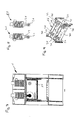
- the press 1 according to the Fig. 1 to 9 has a press table 10, a press frame 12, a machine head or press head 14 and a plunger 16.
- the machine head 14 may also be referred to as the machine upper part or press upper part.
- the press frame 12 has four columns 18 in the present embodiment.
- a plurality of drives 20 are provided, which are each here as a linear electric motor 20, and in particular designed as a servomotor linear electric motor, are formed.
- Fig. 1 how good the Fig. 1 can be removed, 14 chambers 22a, 22b, 22c and 22d are formed in this embodiment in the press upper part or press head, in each of which one of the linear electric motors 20 is arranged. In this embodiment, four linear electric motors 20 are provided, but the number may also vary.
- linear electric motors 20 can alternatively also be integrated in the press table 10, as a result of which installation space can be saved upwards.
- a lateral arrangement of the linear electric motors 20 may alternatively be provided.
- the columns 18 of the press frame 20 are arranged on the four corners of an imaginary rectangular contour.
- the columns 18 are here so that they carry the press head 14.
- the linear electric motors 20 each have a designed as a drive axis 24 linearly displaceable part, which can be moved axially during operation of the linear electric motor 20 and axially moved back and forth, in particular by means of a or a plurality of magnetic fields or by means of a plurality of magnetic poles of the linear electric motor 20th
- an eye 26 is provided on the linear electric motor 20 far end of the drive shaft 24, wherein this eye 26 of the coupling with the plunger 16 is used.
- the plunger 16 has a substantially rectangular outer contour and is designed so that it ensures the best possible rigidity. In the exemplary embodiment, this is so that four plates 28, 30, 32, 34 which are essentially height-related form a kind of rectangular frame, the parallel plates 32 and 34 forming short sides and the parallel plates 28 and 30 forming long sides of a rectangle , However, the short sides 34, 32 may be longer than the spacing of the plates 28 and 30, so that the Plates 32, 34 end over the plate 28 and 30 protrude.
- triangular plates 36 are formed on the respective abutting plates in the region in which each of the shorter plates 32, 34 project beyond the plates 28, 30. In the exemplary embodiment shown, this is such that three triangular plates 36 are integrally formed in each of these corner areas, one bottom, one top and one substantially in the middle being formed.
- plates 38, 40 are provided, which here connect the plates 32 and 34 and, for example - as in Fig. 9 shown - parallel to the plates 28 and 30 run. It could, however, also be provided, for example, that stiffening plates in the manner of a truss pattern are arranged within the frame.
- a bolt extends through two plates for each of the linear electric motors 20. This is so here that two bolts 42 are respectively mounted in the plate 30 and the adjacent plate 40 and two bolts 42 are respectively mounted in the plate 28 and in the adjacent plate 40. In this state, these bolts 42 each extend through an eye 26 of a linear electric motor 20th
- the plunger 16 further includes a bottom plate 44 which Fig. 2 can be seen.
- the bottom plate 44 has a first receiving area 46 for receiving a tool, not shown.
- the receiving region 46 has a plurality of grooves 48, which are designed T-shaped in this embodiment.
- the press table 10 or the press table top has a second receiving area on its upper side 50 for a second tool, which is also not shown.
- This second receiving region 50 is formed by a plurality of grooves 52, which for example likewise have a T-shaped cross-sectional profile, or has such.
- the linear electric motors 20 are positioned in the press table 10, for example, corresponding power transmission paths, which are formed for example by L-shaped parts and which provide the coupling to the plunger, in the region of the press frame or run between the columns of the press frame.
- the in the Fig. 1 to 9 The design shown can be, for example, part of a stamping machine or part of a cutting machine or part of a thermoforming machine.
- the invention has various advantages. So it offers a high variability, that means in particular a freely programmable ram speed in every position. Furthermore, tryout operation is possible.
- the design can be used according to a Exzenterstanzautomat or according to a hydraulic press. It is also advantageous that no more synthetic lubricating or hydraulic oils are required. Next occur no rotating bearings, so no lubrication required is.
- the invention offers a high degree of variability, at least in its developments.
- the linear movement of the plunger 16 is realized directly by a linear movement of the drive. There is no or no conversion of a rotational to a linear movement. Thus, less energy losses occur.
- Fig. 10 shows a second embodiment of the invention in a schematic view, wherein like or corresponding parts are provided with the reference numerals, which are also in the Fig. 1 to 9 were used.
- the design according to Fig. 10 corresponds essentially to the design according to the Fig. 1 to 9 so that on the Fig. 1 to 9 subject to the following deviations also for the design according to Fig. 10 applies.
- Fig. 10 is the arrangement of the linear electric motors 20 - here, for example, four may be provided - different from the design according to the Fig. 1 to 9 not in the press head 14, but in the press table 10, so that the corresponding power transmission path to the plunger 16 is modified accordingly.
- the drive shaft 24 is connected to an angle 60 which engages laterally in the plunger 16.
- the drive axle 24 without Interposition of an angle be connected directly to the plunger 16, for example, laterally or from below.
- embodiments of the invention there are fewer health problems for persons than in the design according to him EP 0 943 422 A2 because the magnetic fields do not have to be that strong.
- the magnetic fields can be easily shielded.
- embodiments of the invention can be made oil and / or fat free.
- the arrangement of the linear electric motors 20 in the press table 10 usually saves space upwards.
- the power transmission path from the linear electric motor 20 to the plunger 16 can be formed for example by the drive axle 24 and / or rods, so that the access to the working area 62 not appreciably, or at least to a lesser extent than in the design according to the EP 0 943 422 A2 , is impaired.
- Fig. 11 to 13 show an exemplary linear electric motor 20, the inventive designs, such as in the design as a drive for the plunger 16 can be used in the Fig. 1 to 9 is shown, or in the design, in Fig. 10 is shown.
- Fig. 11 is a front view of the linear electric motor 20, while Fig. 12 a section along the line XII-XII Fig. 11 shows and while Fig. 13 a section along the line XIII-XIII Fig. 11 shows.
- the linear electric motor 20 has a plurality of magnetic poles 70, 72, 74, 76, 78, 80, which are arranged offset axially relative to the central longitudinal axis 82 of the linear electric motor 20.
- poles 70, 72, 74, 76, 78, 80 are formed by means of coils 84, 86, 88, which are also arranged axially offset with respect to the central longitudinal axis 82.
- Each of these coils 84, 86, 88 is wound on a bobbin 90, 92, 94 on its radially outer surface.
- each of the coils 84, 86, 88 are traversed by an electric current and is accordingly made of suitable, electrically conductive material, such as metal, in particular copper.
- suitable, electrically conductive material such as metal, in particular copper.
- each of the coils 84, 86, 88 is wound from a corresponding wire.
- the magnetic field forming as a result of the current flow through the respective coil 84, 86, 88 then generates in each case one plus pole and one negative pole in the interior 96, which will be discussed below.
- the magnetic poles 70, 72, 74, 76, 78, 80 must or should therefore not permanently act as positive pole or negative pole, but rather can be made by energizing the respectively corresponding coil to a positive pole or negative pole. This is particularly so that, if one of these coils 84, 86, 88 is traversed by an electric current, the relevant Coil 84, 86, 88 generates a magnetic field with its associated previously addressed poles 70 and 72, or 74 and 76, or 78 and 80. In the above-mentioned pairwise order, these poles are assigned to the coils 84, 86 and 88.
- poles 70, 72, 74, 76, 78, 80 need not be physically tangible, and thus can be formed by the magnetic field itself.
- Each of the coil supports 90, 92, 94 may also be made of electrically conductive material, such as metal, in particular copper, or of an electrically insulating material.
- a linearly displaceable part is arranged, which is also referred to as rotor or drive axle 24, and in the direction of the axis 82 by means of the coils 84, 86th , 88 is axially displaceable.
- This drive axle 24 is completely or partially designed as a permanent magnet and accordingly forms magnetic poles 100, 102 at its axial ends 104, 106.
- the drive shaft 24 may be provided with an eye 26 for coupling to the plunger 16, or be fixedly coupled to an intermediate portion 107, which in turn has the eye 26. Instead of the eye 26, however, a differently designed coupling point for the plunger 16 may be provided.
- Axial between the coils 84, 86, 88 and / or coil supports 90, 92, 94 may be provided electrical and / or magnetic insulators 108, 110, however, have radially inwardly through holes 112, so that the rotor 24 can enter or pass unhindered ,
- a switching device 140 is provided, by means of which optionally one, possibly also simultaneously or temporally overlapping a plurality of the coils 84, 86, 88 is coupled to the electrical voltage source 138 such that the relevant coil 84, 86, 88 of an electric Current is flowing through and the coil 84, 86, 88 associated with these poles 70, 72, 74, 76, 78, 80, ie magnetic plus pole and magnetic negative pole, training or be activated.
- a control device 142 which the energization of the coils 84, 86, 88 and / or the switching positions of the switching device 140 to cause the respectively desired axial displacement of the rotor 24, and thus of the plunger 16.
- This control device 142 which may also have other control functions, such as the control of the workpiece movement by the press, controls the coils 84, 86, 88 in a defined order, so as to effect the respective desired axial displacement of the rotor 24.
- the driving takes place so that the axial displacement by the respective interaction of the poles 100, 102 of the rotor 24 with the forming poles 70, 72, 74, 76, 78, 80 of the respective energized coil 84, 86, 88, comes about. It is exploited that the same magnetic poles, ie two Magnetic positive poles or two magnetic negative poles, repelled and different poles, ie a positive magnetic pole and a negative magnetic pole, tighten.
- the drive shaft 24, and thus the plunger 16 can be moved axially, optionally in either one of the two opposite orientations.
- the drive shaft 24, and thus the plunger 16 with the tool mounted or held thereon can thus be reciprocated for machining the workpiece.
- This movement can also be controlled by means of the control device 142 so that it is tuned to the feed of the workpiece and its timing.
- the drive shaft 24 can be stopped and held in predetermined axial positions or in any axial position of its axial travel range.
- - depending on the desired holding position and / or number of coils 84, 86, 88 - one or more coils 84, 86, 88 are energized such that in the desired position by means of the poles 70th , 72, 74, 76, 78, 80 of the currently energized coils 84, 86, 88 an axial force equilibrium on the drive axle 24 is generated.
- power relationships can also be a damped braking movement of the drive shaft 24 are generated.
- the corresponding tuning of the current supply in the one or more coils 84, 86, 88 can be controlled by the control device 142.
- a plurality of coils 84, 86, 88 can also be supplied with current at the same time or overlapping in time.
- the respective axial position can also be determined by calculation in the control device 142 as a function of previous control characteristics.
- a rotation lock for the rotor 24 may be present, which counteracts a rotation of the rotor 24 about the axis 82. While in the Fig. 11 to 13 the bobbin carriers 90, 92, 94 are hollow cylindrical and the rotor 24 are shown cylindrically, but other cross-sectional shapes, such as, for example, triangular, quadrangular, pentagonal, hexagonal or the like may also be provided in each case.
Abstract
Description
Die Erfindung betrifft eine Presse zum Erzeugen einer Druckkraft für die Bearbeitung eines Werkstücks.The invention relates to a press for generating a pressure force for the machining of a workpiece.
Pressen sind bereits in verschiedenen Ausgestaltungen bekannt. Derartige Pressen dienen zum Erzeugen einer Druckkraft für die Bearbeitung eines Werkstücks. Sie werden beispielsweise in Stanzautomaten oder in Tiefzieh- oder Schneidmaschinen eingesetzt. In der Regel weisen Pressen einen Pressentisch, ein Pressengestell, einen Stößel sowie einen Antrieb zum Antreiben dieses Stößels auf.Presses are already known in various embodiments. Such presses are used to generate a compressive force for the machining of a workpiece. They are used for example in stamping machines or in thermoforming or cutting machines. In general, presses on a press table, a press frame, a plunger and a drive for driving this plunger on.
Beispiele für bekannte Pressen sind die sogenannten Tryout-Pressen oder die sogenannten Hydraulikpressen.Examples of known presses are the so-called tryout presses or the so-called hydraulic presses.
Eine weitere bekannte Art von Pressen stellen die sogenannten Exzenterpressen dar. Exzenterpressen weisen einen Antrieb mit drehend getriebener Antriebswelle auf, wobei diese rotierende Antriebsbewegung der Antriebswelle in eine lineare Bewegung des Stößels umgewandelt wird. Zum Zwecke dieser Umwandlung werden typischerweise Exzenter eingesetzt.Another known type of presses are the so-called eccentric presses. Eccentric presses have a drive with a rotationally driven drive shaft, wherein this rotating drive movement of the drive shaft is converted into a linear movement of the tappet. For the purpose of this conversion, eccentrics are typically used.
Eine weitere Möglichkeit zur Erzeugung der erforderlichen Linearbewegung des Stößels besteht darin, dass ein Linearantrieb mittels einer Spindel ausgebildet wird. Zu diesem Zweck wird eine drehend angetriebene Welle, wie beispielsweise Antriebswelle eines Motors, mittels der Spindel in eine Linearbewegung gewandelt.Another possibility for generating the required linear movement of the plunger is that a linear drive is formed by means of a spindle. For this purpose, a rotationally driven shaft, such as the drive shaft of a motor, is converted by means of the spindle into a linear movement.
Die Gestaltungen mit Antriebssystemen der zuletzt genannten Art basieren also ebenso wie die Antriebssysteme von Exzenterpressen darauf, dass eine rotierende Bewegung in eine Linearbewegung umgewandelt wird. Bei dieser Umwandlung der Rotationsbewegungen in lineare Bewegungen treten allerdings nennenswerte energetische Verluste bzw. Reibung auf (insbesondere durch Getriebe- und Spindelübersetzungen) denen bzw. der allerdings durch den Einsatz von Schmierölen, die allerdings zusätzliche Kosten verursachen, entgegengewirkt werden kann. Pressen der bekannten Art erfordern häufig in verhältnismäßig kurzen Zeiteinheiten mehrere Hektoliter Schmieröl.The designs with drive systems of the latter type are therefore based, just like the drive systems of eccentric presses, on the fact that a rotating movement is converted into a linear movement. In this conversion of the rotational movements in linear movements, however, occur appreciable energy losses or friction on (in particular by gear and spindle ratios) which or that, however can be counteracted by the use of lubricating oils, which, however, cause additional costs. Presses of the known type often require several hectoliters of lubricating oil in relatively short time units.
Aus der
Derartige, gemäß der
Dementsprechend liegt der Erfindung die Aufgabe zu Grunde, eine Presse mit geringem Schmiermittelbedarf und/oder geringen energetischen Verlusten zu schaffen, die eine gute und ggf. betriebsangepasste Bauraumausnutzung ermöglicht.Accordingly, the invention is based on the object to provide a press with low lubricant consumption and / or low energy losses, which allows a good and possibly operationally adapted space utilization.
Erfindungsgemäß wird eine Presse gemäß Anspruch 1 oder gemäß Anspruch 7 vorgeschlagen. Beispiele für eine derartige Presse können den Unteransprüchen sowie der folgenden Beschreibung entnommen werden.According to the invention, a press according to
Erfindungsgemäß wird also eine Presse zum Erzeugen einer Druckkraft für die Bearbeitung eines Werksstücks vorgeschlagen, die einen Maschinentisch bzw. Pressentisch, ein Maschinengestell bzw. Pressengestell, einen Stößel sowie wenigstens einen Antrieb zum Antreiben des Stößels aufweist. Dieser Antrieb des Stößels, bzw. mehrere oder alle Antriebe des Stößels, sind als Linear-Elektromotor ausgebildet. Der, mehrere oder alle Linear-Elektromotoren weisen mehrere versetzt zueinander angeordnete magnetische Pole sowie ein mittels dieser Pole linear verlagerbares Teil, wie beispielsweise Antriebsachse, auf. Die magnetischen Pole wenigstens eines Linear-Elektromotors werden von sich um eine Achse herum erstreckenden Spulen gebildet, die bezüglich dieser Achse axial versetzt zueinander angeordnet sind. Das linear verlagerbare Teil erstreckt sich in Richtung dieser Achse und ist mittels der Spulen in Richtung dieser Achse linear verlagerbar.According to the invention, therefore, a press is proposed for generating a compressive force for the machining of a workpiece, which has a machine table or press table, a machine frame or press frame, a plunger and at least one drive for driving the plunger. This drive of the plunger, or more or all drives of the plunger are formed as a linear electric motor. The, several or all linear electric motors have a plurality of mutually offset magnetic poles and a means of these poles linearly displaceable part, such as drive axle, on. The magnetic poles of at least one linear electric motor are formed by coils extending around an axis which are axially offset with respect to this axis. The linearly displaceable part extends in the direction of this axis and is linearly displaceable by means of the coils in the direction of this axis.
Im Sinne der vorliegenden Anmeldung ist der Begriff des "Werkstücks" weitgefasst zu verstehen. So kann ein Werkstück beispielsweise ein vereinzeltes Werkstück sein oder beispielsweise auch zusammenhängendes Material, das vereinzelt wird, wie beispielsweise durch Schneiden, Stanzen oder dergleichen.For the purposes of the present application, the term "workpiece" is to be understood broadly. For example, a workpiece can be an isolated workpiece or, for example, also contiguous material that is separated, for example by cutting, punching or the like.
Die Bearbeitung des Werkstücks kann im Sinne der vorliegenden Erfindung ebenfalls auf unterschiedlichste Weise erfolgen. Beispielsweise kann die Bearbeitung in einem "Tiefziehen" oder einem "Schneiden" oder einem "Stanzen" bestehen.The machining of the workpiece can also take place in various ways in the sense of the present invention. For example, the processing may consist in a "deep drawing" or a "cutting" or a "punching".
Dementsprechend kann die erfindungsgemäße Presse beispielsweise Bestandteil einer Tiefziehmaschine oder einer Stanzmaschine oder einer Schneidmaschine oder auch einer anders gearteten Maschine sein, bei der eine Druckkraft zur Bearbeitung eines Werkstücks erforderlich ist.Accordingly, the press according to the invention may for example be part of a thermoforming machine or a punching machine or a cutting machine or another type of machine in which a pressure force for machining a workpiece is required.
In vorteilhafter Ausgestaltung ist der Linear-Elektromotor als Servo-Motor ausgebildet. Der Linear-Elektromotor kann insbesondere so ausgebildet sein, dass sein linear verlagerbares Teil eine Antriebsachse ist, die in ein Magnetfeld bzw. mehrere Magnetfelder des Linear-Elektromotors hineinragt bzw. in diesen angeordnet ist und mittels des bzw. der Magnetfelder axial bewegt werden kann. Dies kann insbesondere so sein, dass die das linear verlagerbare Teil bzw. Antriebsachse mittels des bzw. der Magnetfelder axial hin und her bewegt werden kann. Die Antriebsachse bzw. das linear verlagerbare Teil ist also insbesondere eine Art Kern des Elektromotors, der axial beweglich ist. Diese Magnetfelder werden insbesondere von den Polen gebildet. Die Spulen können insbesondere stromdurchflossen sein bzw. werden stromdurchflossen, um die entsprechenden Magnetpole zu bewirken.In an advantageous embodiment, the linear electric motor is designed as a servo motor. In particular, the linear electric motor may be designed such that its linearly displaceable part is a drive axle which projects into or is arranged in a magnetic field or a plurality of magnetic fields of the linear electric motor and can be moved axially by means of the magnetic field or fields. This can in particular be such that the linearly displaceable part or drive axle can be moved axially back and forth by means of the magnetic field (s). The drive shaft or the linearly displaceable part is therefore in particular a kind of core of the electric motor, which is axially movable. These magnetic fields are formed in particular by the poles. The coils can in particular be current-carrying or are current-flowed through to effect the corresponding magnetic poles.
Es kann vorgesehen sein, dass der Stößel mit wenigstens einem ersten Werkzeug oder mehreren ersten Werkzeugen gekoppelt ist und zwar insbesondere direkt gekoppelt ist. Zu diesem Zweck kann an dem Stößel eine erste Werkzeugaufnahme für die Aufnahme des ersten Werkzeuges vorgesehen sein. Die erste Werkzeugaufnahme kann beispielsweise aus einer Mehrzahl von Nuten, wie insbesondere T-förmigen Nuten, bestehen.It can be provided that the plunger is coupled to at least one first tool or a plurality of first tools, and in particular is directly coupled. For this purpose, a first tool holder for receiving the first tool can be provided on the plunger. The first tool holder may for example consist of a plurality of grooves, in particular T-shaped grooves.
Es kann auch vorgesehen sein, dass an dem Pressentisch eine zweite Werkzeugaufnahme für die Aufnahme wenigstens eines zweiten Werkzeuges vorgesehen ist. Zu diesem Zweck kann der Pressentisch, und zwar insbesondere die obere Oberfläche oder Tischplatte des Pressentisches, eine oder mehrere zweite Werkzeugaufnahmen für die Aufnahme eines zweiten Werkzeuges aufweisen. Die zweite Werkzeugaufnahme kann beispielsweise aus einer Mehrzahl von Nuten, wie insbesondere T-förmigen Nuten, bestehen.It can also be provided that a second tool holder for receiving at least one second tool is provided on the press table. For this purpose, the press table, in particular the upper surface or table top of the press table, one or more second tool holders for receiving a second tool. The second tool holder may for example consist of a plurality of grooves, in particular T-shaped grooves.
Der Pressentisch kann, insbesondere auf seiner Oberseite, mit einer oder mehreren Führungseinrichtungen und/oder mit einer oder mehreren Halteeinrichtungen zum Führen bzw. Halten des Werkstücks versehen sein. Diese können beispielsweise lösbar montiert sein.The press table can, in particular on its upper side, be provided with one or more guide devices and / or with one or more holding devices for guiding or holding the workpiece. These can for example be detachably mounted.
Für das Beispiel des Tiefziehens kann ein erstes Werkzeug beispielsweise ein Stempel sein und ein zweites Werkzeug ein Ziehring bzw. eine Matrize. Ein weiteres zweites Werkzeug kann ein Niederhalter sein.For the example of deep drawing, for example, a first tool may be a stamp and a second tool may be a drawing ring or a die. Another second tool may be a hold-down.
Es kann vorgesehen sein, dass die Kraftübertragungsstrecke zwischen dem Linear-Elektromotor bzw. dessen linear verlagerbarem Teil bzw. dessen Antriebsachse und dem Stößel bzw. dem ersten Werkzeug oder der ersten Werkzeugaufnahme frei von rotierenden Teilen ist. Ein linear verlagerbares Teil des Linear-Elektromotors bzw. eine Antriebsachse des Linear-Elektromotors - d.h. insbesondere eine Achse, die in das oder die Magnetfelder des Elektromotors ragt und vom diesem bzw. von diesem angetrieben wird - kann direkt mit dem Stößel gekoppelt sein. Dies kann beispielsweise so sein, dass die angesprochene Antriebsachse bzw. das angesprochene linear verlagerbare Teil und der angesprochene Stößel direkt über eine Schraubverbindung oder dergleichen miteinander verbunden sind. Es kann auch vorgesehen sein, dass ein Bolzen oder eine Bolzenanordnung eine derartige direkte Verbindung herstellt.It can be provided that the force transmission path between the linear electric motor or its linearly displaceable part or its drive axis and the plunger or the first tool or the first tool holder is free of rotating parts. A linearly displaceable part of the linear electric motor or a drive axis of the linear electric motor - ie in particular an axis which projects into the one or more magnetic fields of the electric motor and is driven by or from this - can be coupled directly to the plunger. This can for example be such that the addressed drive axle or the addressed linearly displaceable part and the mentioned plunger are connected to each other directly via a screw or the like. It can also be provided that a bolt or a bolt arrangement produces such a direct connection.
Gemäß einer alternativen Ausgestaltung kann eine Kopplung zwischen einem linear verlagerbaren Teil bzw. einer Antriebsachse eines Linear-Elektromotors und dem Stößel auch indirekt, beispielsweise über einen Kniehebel, erfolgen. Ein solcher Kniehebel kann insbesondere schwenkbar gelagert sein, beispielsweise schwenkbar am Pressentisch oder am Pressengestell. Es sei angemerkt, dass insbesondere vorgesehen ist, dass ein solcher Kniehebel im Betrieb einen Schwenkbereich überfährt, der kleiner als 360 Grad, insbesondere kleiner gleich 270 Grad, insbesondere kleiner gleich 180 Grad, insbesondere kleiner gleich 150 Grad, und beispielsweise im Bereich von 120 Grad bis 130 Grad liegt. Auch kleinere vom Kniehebel überfahrene Winkel bzw. Wege in Schwenkrichtung können vorgesehen sein.According to an alternative embodiment, a coupling between a linearly displaceable part or a drive axis of a linear electric motor and the plunger also indirectly, for example via a toggle, done. Such a toggle lever may in particular be pivotally mounted, for example pivotally mounted on the press table or on the press frame. It should be noted that in particular it is provided that such a toggle overruns in operation a pivoting range, which is less than 360 degrees, in particular less than or equal to 270 degrees, in particular less than or equal to 180 degrees, in particular less than or equal to 150 degrees, and for example in the range of 120 degrees up to 130 degrees. Smaller angles or paths in the pivoting direction that are traveled by the toggle lever can also be provided.
In diesen Zusammenhang sei angemerkt, dass - soweit im Rahmen der Würdigung des Standes der Technik davon gesprochen wurde, dass dort rotierende Teile vorgesehen sind, dies insbesondere so ist, dass die rotierenden Teile, insbesondere mehrfach aufeinander folgend, einen Winkel überfahren, der größer oder gleich 360 Grad ist, also vollständige Umdrehungen ausführen.In this context, it should be noted that - as far as in the context of the appreciation of the prior art was spoken of that there rotating parts are provided, this is in particular such that the rotating parts, in particular several times consecutively, over an angle, the larger or is equal to 360 degrees, so perform complete revolutions.
Der Linear-Elektromotor kann oberhalb des Pressentisches angeordnet sein. Dies kann beispielsweise so sein, dass die Presse einen Pressenkopf aufweist, der oberhalb des Pressentischs angeordnet und von diesem Pressentisch, insbesondere vertikal, beabstandet ist, und in welchen der Linear-Elektromotor integriert ist. Es ist insbesondere vorgesehen, dass (vertikal) zwischen dem Pressentisch und dem Pressenkopf ein Arbeitsbereich für das Bearbeiten von Werkstücken gebildet wird.The linear electric motor can be arranged above the press table. This may for example be such that the press has a press head, which is arranged above the press table and spaced from this press table, in particular vertically, and in which the linear electric motor is integrated. It is particularly provided that (vertically) between the press table and the press head, a work area for the machining of workpieces is formed.
Der Stößel ist insbesondere oberhalb des Pressentisches angeordnet. Bei einer Anordnung des Linear-Elektromotors oberhalb des Pressentisch kann insbesondere vorgesehen sein, dass der Stößel zwischen dem Werkstück bzw. der ersten und/oder zweiten Werkzeugaufnahme und dem Linear-Elektromotor angeordnet ist.The plunger is arranged in particular above the press table. In an arrangement of the linear electric motor above the press table can be provided in particular that the plunger between the workpiece or the first and / or second tool holder and the linear electric motor is arranged.
Es kann auch vorgesehen sein, dass der Linear-Elektromotor in dem Pressentisch integriert ist. Dies kann beispielsweise so sein, dass das Werkstück bzw. die erste und/oder zweite Werkzeugaufnahme zwischen dem Stößel und dem Linear-Elektromotor angeordnet ist. Eine derartige Ausgestaltung, bei der der Linear-Elektromotor im Pressentisch integriert ist bzw. unterhalb der Tischplatte bzw. oberen Tischoberfläche des Pressentischs angeordnet ist, hat den besonderen Vorteil, dass eine solche Ausgestaltung Bauraum nach oben sparen kann.It can also be provided that the linear electric motor is integrated in the press table. This can for example be such that the workpiece or the first and / or second tool holder is arranged between the plunger and the linear electric motor. Such a configuration, in which the linear electric motor is integrated in the press table or is arranged below the table top or upper table surface of the press table, has the particular advantage that such a configuration can save upwards space.
Es kann vorgesehen sein, dass die bzw. eine Antriebsachse bzw. ein bzw. das linear verlagerbare Teil des Linear-Elektromotors parallel zur Stoßrichtung des Stößels gelegen ist. Es kann aber auch vorgesehen sein, dass eine derartige Antriebsachse des Linear-Elektromotors quer, insbesondere senkrecht, zur Stoßrichtung des Stößels gelegen ist. Bei einer Ausgestaltung, bei der die Antriebsachse des Linear-Elektromotors senkrecht zur Stoßrichtung des Stößels gelegen ist, kann die Kraftübertragung von der linear verlagerbaren Teil bzw. der Antriebsachse auf den Stößel beispielsweise mittels Keilflächen oder mittels eines Kniehebels erfolgen. Es kann vorgesehen sein, dass der Stößel mit Führungen, wie Linearführungen, versehen ist. Beispielsweise können vier Linearführungen für den Stößel vorgesehen sein. Es kann aber auch vorgesehen sein, dass mehr als vier Linearführungen oder weniger als vier Linearführungen für den Stößel vorgesehen sind. Der Stößel kann so sein, dass die in Richtung der Stoßrichtung des Stößels gelegene Höhe dieses Stößels geringer ist, als die sich senkrecht zu dieser Stoßrichtung erstreckende Breite des Stößels und/oder als die sich senkrecht zu dieser Breite und senkrecht zu dieser Stoßrichtung erstreckende Tiefe des Stößels. Der Stößel kann beispielsweise eine Außenkontur aufweisen, die im Wesentlichen rechteckig oder im Wesentlichen quadratisch ist. Es kann vorgesehen sein, dass der Stößel Versteifungen aufweist, um zu verhindern oder zumindest die Gefahr zu mindern, dass der Stößel unter Last Verformungen erfährt.It can be provided that the or a drive axle or one or the linearly displaceable part of the linear electric motor is located parallel to the thrust direction of the plunger. But it can also be provided that such a drive axis of the linear electric motor is located transversely, in particular perpendicular, to the thrust direction of the plunger. In an embodiment in which the drive axis of the linear electric motor is located perpendicular to the thrust direction of the plunger, the power transmission from the linearly displaceable part or the drive axle on the plunger can be done for example by means of wedge surfaces or by means of a toggle lever. It can be provided that the plunger is provided with guides, such as linear guides. For example, four linear guides may be provided for the plunger. However, it can also be provided that more than four linear guides or less than four linear guides are provided for the plunger. The plunger may be such that the height of this plunger in the direction of the impact direction of the plunger is less than the width of the plunger extending perpendicularly to this impact direction and / or perpendicular to this width and perpendicular to this thrust extending depth of the plunger. The plunger may for example have an outer contour that is substantially rectangular or substantially square. It may be provided that the plunger has stiffeners to prevent or at least reduce the risk that the plunger undergoes deformations under load.
Es kann vorgesehen sein, dass die Presse zum Verhindern des Durchschlagens des Stößels bei ausbleibender Stromversorgung des Linear-Elektromotors eine Hochhaltebremse für das linear verlagerbare Teil bzw. für die Antriebsachse aufweist.It may be provided that the press to prevent the breakdown of the plunger in the absence of power to the linear electric motor has a hold-brake for the linearly displaceable part or for the drive axle.
Eine derartige Hochhaltebremse kann beispielsweise als formschlüssige Bremse oder als eine reibschlüssige Bremse ausgebildet sein, wobei auch eine Kombination dieser Bremstypen vorgesehen sein kann. Beispielsweise kann die Bremse eine formschlüssige oder reibschlüssige Zange mit zwei Bremsbacken aufweisen, welche das linear verlagerbare Teil bzw. die Antriebsachse umgreifen kann. Es kann auch vorgesehen sein, dass an dem linear verlagerbaren Teil bzw. an der Antriebsachse ein Zahn angeordnet ist, der zum Bremsen mit einer Zahnstange zusammenwirkt. Dabei kann vorgesehen sein, dass die Zahnstange federbetätigt in Richtung des Zahns bzw. einer Zahn/Zahnstangen-Eingriffsposition gedrückt wird, wobei beispielsweise ein Elektromotor, der von dem wenigstens einen Antrieb des Stößel bzw. den Linear-Elektromotoren verschieden sein kann oder einer Antriebe des Stößel bzw. dieser Linear-Elektromotoren ist, entgegen der Federkraft eine Kraft auf die Zahnstange ausübt, um diese in einer Außereingriffsposition mit dem Zahn zu halten. Wenn dann die Stromversorgung unterbrochen wird, reißt evident die von dem für die Hochhaltebremse vorgesehenen Elektromotor, der auch Linear-Elektromotor sein kann, auf die Zahnstange ausgeübte Kraft ab, so dass die Zahnstange unter der Wirkung der Federkraft mit den an dem linear verlagerbaren Teil bzw. an der Antriebsachse angeordneten Zähnen in Eingriff gebracht wird und eine Axialverschiebung dieses linear verlagerbaren Teils bzw. dieser Antriebsachse verhindert. Dadurch wird dann das Durchschlagen des (mit dem linear verlagerbaren Teil bzw. mit der Antriebsachse gekoppelten) Stößels verhindert, also das Auftreten einer im Wesentlichen ungebremsten Stößelbewegung in Richtung des Pressentisches.Such a holding brake may for example be designed as a positive brake or as a frictional brake, wherein a combination of these types of brakes may be provided. For example, the brake may have a positive or frictional forceps with two brake shoes, which can embrace the linearly displaceable part or the drive axle. It can also be provided that a tooth is arranged on the linearly displaceable part or on the drive axle, which cooperates with a rack for braking. It can be provided that the rack is spring-actuated in the direction of the tooth or a tooth / rack engaging position is pressed, for example, an electric motor that may be different from the at least one drive of the plunger or the linear electric motors or a drives of Tappet or this linear electric motors, against the spring force exerts a force on the rack to hold them in a disengaged position with the tooth. Then, when the power supply is interrupted, cracked by the intended for the holding brake electric motor, which may also be linear electric motor, exerted on the rack force from, so that the rack under the action of the spring force with the linear on the displaceable part or arranged on the drive axle teeth is engaged and prevents axial displacement of this linearly displaceable part or this drive axle. As a result, the penetration of the plunger (coupled to the linearly displaceable part or to the drive axis) is prevented, that is to say the occurrence of a substantially unrestrained plunger movement in the direction of the press table.
Bei der alternativen Ausgestaltung einer derartigen Hochhaltebremse mit formschlüssiger oder reibschlüssiger Zange und zwei Bremsbacken kann ebenfalls eine Federkraft auf die Bremsbacken wirken, die mittels eines für die Hochhaltebremse vorgesehenen Elektromotors in entsprechender Weise in einer Außereingriffsposition gehalten werden, solange die Stromversorgung gegeben ist. Bei ausbleibender Stromversorgung bewegen sich die Bremsbacken an das linear verlagerbare Teil bzw. an die Antriebsachse und halten diese in ihrer Axialstellung.In the alternative embodiment of such a holding brake with positive or frictional forceps and two brake shoes can also act on the brake shoes, which are held in a disengaged position by means of an electric motor provided for the holding brake in a corresponding manner in a disengaged position, as long as the power supply is given. In the absence of power supply, the brake shoes move to the linearly displaceable part or to the drive axle and keep them in their axial position.
Eine Hochhaltebremse kann beispielsweise hydraulisch oder mechanisch ausgebildet sein. Dies ist insbesondere so, dass dann, wenn Strom wegfällt, die Hochhaltebremse von einer gelösten Position in eine Bremsposition bewegt wird, um eine fortgesetzte Bewegung des linear verlagerbaren Teils bzw. der Antriebsachse bzw. des Stößels zu unterbinden.A holding brake can be designed, for example, hydraulically or mechanically. This is in particular such that, when power is removed, the hold-up brake is moved from a released position to a braking position to prevent continued movement of the linearly displaceable part or the drive shaft or the plunger.
Bei Ausgestaltungen, bei denen der Linear-Elektromotor im Pressentisch integriert ist, kann vorgesehen sein, dass am Stößel ein Winkelelement - insbesondere fest - ausgebildet bzw. angeformt ist, über das ein bzw. das linear verlagerbare Teil bzw. die bzw. eine jeweilige Antriebsachse mit dem Stößel gekoppelt ist. Beim Vorhandensein mehrerer Linear-Elektromotoren, die im Pressentisch integriert sind, kann insbesondere vorgesehen sein, dass mehrere derartiger Winkel vorgesehen sind. Wie bereits angesprochen können die Antriebe bzw. Antriebseinheiten von oben oder von unten montiert sein, so dass eine drückende oder ziehende Bewegung auf den Stößel ausgeübt wird. Der Antrieb bzw. Elektromotor bzw. die Antriebseinheiten bzw. Antriebe können hinsichtlich der Anzahl oder Position auch frei gewählt werden. Beispielsweise kann ein Antrieb zentral mittig (von) oben angeordnet sein oder drei Antriebe bzw. Linear-Elektromotoren können mittig oben bzw. von oben angeordnet sein. Es kann aber auch vorgesehen sein, dass ein, zwei oder drei Linear-Elektromotoren unten bzw. von unten angeordnet sind. Ferner kann vorgesehen sein, dass vier Antriebe bzw. Linear-Elektromotoren oben bzw. von oben oder unten bzw. von unten angeordnet sind. Ferner kann vorgesehen, dass vier Antriebe bzw. Linear-Elektromotoren und zusätzlich ein Linear-Elektromotor mittig (von) oben angeordnet sind. Es kann aber auch vorgesehen sein, dass acht Linear-Elektromotoren oben bzw. von oben oder unten bzw. von unten angeordnet sind. Es sei angemerkt, dass diese Anzahl Linear-Elektromotoren die Erfindung nicht beschränken soll. Es kann beispielsweise jede beliebige ganzzahlige Anzahl an Linear-Elektromotoren vorgesehen sein, die jeweils von oben bzw. oben oder von unten bzw. unten, also insbesondere in den Pressentisch integriert, angeordnet sind. So können beispielsweise 5 oder 6 oder 7 oder 9 oder 10 oder 11 oder 12 oder 13 oder 14 oder 15 oder 16 oder 17 oder 18 oder 19 oder 20 oder 21 oder 22 oder 22 oder 23 oder 24 Linear-Elektromotoren vorgesehen sein. Auch eine höhere Anzahl an Linear-Elektromotoren kann vorgesehen sein. Auch Kombinationen aus Linear-Elektromotoren, die oberhalb des Pressentisches angeordnet sind, und Linear-Elektromotoren, die im Tisch integriert sind, kann vorgesehen sein. Die Antriebe bzw. Antriebseinheiten bzw. Linear-Elektromotoren können Kniehebel als Kraftverstärker antreiben. Über ein Kniehebelsystem kann beispielsweise auch ein horizontaler Anbau ermöglicht werden, also insbesondere auch horizontale Anordnung der Antriebsachse bzw. Antriebsachsen des bzw. der Linear-Elektromotors bzw. -Elektromotors.In embodiments in which the linear electric motor is integrated in the press table, it can be provided that an angle element - in particular fixed - is formed or formed on the plunger via which one or the linearly displaceable part or the or a respective drive axle coupled with the plunger. In the presence of a plurality of linear electric motors, which are integrated in the press table, may be provided in particular that a plurality of such angles are provided. As already mentioned, the drives can or drive units be mounted from above or from below, so that a pushing or pulling movement is exerted on the plunger. The drive or electric motor or the drive units or drives can also be freely selected with regard to the number or position. For example, a drive can be arranged centrally (from) above or three drives or linear electric motors can be arranged centrally above or from above. But it can also be provided that one, two or three linear electric motors are arranged below or from below. Furthermore, it can be provided that four drives or linear electric motors are arranged at the top or from above or below or from below. Furthermore, it is provided that four drives or linear electric motors and additionally a linear electric motor are arranged centrally (from) above. But it can also be provided that eight linear electric motors are arranged above or from above or below or from below. It should be noted that this number of linear electric motors is not intended to limit the invention. It can be provided, for example, any integer number of linear electric motors, each of which is arranged from above or above or from below or below, so in particular integrated into the press table. For example, 5 or 6 or 7 or 9 or 10 or 11 or 12 or 13 or 14 or 15 or 16 or 17 or 18 or 19 or 20 or 21 or 22 or 22 or 23 or 24 linear electric motors may be provided. Also, a higher number of linear electric motors can be provided. Combinations of linear electric motors, which are arranged above the press table, and linear electric motors, which are integrated in the table, can be provided. The drives or drive units or linear electric motors can drive toggle as a power amplifier. By means of a toggle lever system, for example, a horizontal attachment can also be made possible, that is to say in particular also horizontal Arrangement of the drive axle or drive axles of or the linear electric motor or -Elektromotors.
Es kann vorgesehen sein, dass mehrere oder alle Linear-Elektromotoren mit genau einem Stößel gekoppelt sind, um diesen anzutreiben.It can be provided that several or all linear electric motors are coupled with exactly one plunger in order to drive it.
Im Rahmen der Offenbarung der vorliegenden Erfindung wird teilweise die Anordnung oder die Gestaltung oder dergleichen eines (als Antrieb für den Stößel dienenden) Linear-Elektromotors, insbesondere beispielhaft, erläutert. Es können allerdings auch mehrere jeweils als Antrieb für denselben Stößel dienende Linear-Elektromotoren vorgesehen sein. Dabei kann jeder dieser mehreren Linear-Elektromotoren so ausgebildet und/oder angeordnet sein, wie der vorerwähnte eine Linear-Elektromotor, sofern sich dadurch nicht offensichtliche Widersprüche ergeben. Ferner kann vorgesehen sein, dass diese mehreren jeweils als Antrieb für denselben Stößel dienenden Linear-Elektromotoren unterschiedlich ausgebildet und/oder angeordnet sind, wobei insbesondere vorgesehen ist, dass unterschiedliche beispielhafte erfindungsgemäße Gestaltungen der Linear-Elektromotoren kombiniert sind. Weiter kann vorgesehen sein, dass mehrere Stößel vorgesehen sind, für deren Antriebe jeweils Vorgesagtes gilt.In the context of the disclosure of the present invention, the arrangement or the design or the like of a (serving as a drive for the plunger) linear electric motor, in particular exemplified explained in part. However, it is also possible to provide a plurality of linear electric motors each serving as a drive for the same ram. In this case, each of these multiple linear electric motors may be formed and / or arranged as the aforementioned a linear electric motor, provided that this does not reveal obvious contradictions. Furthermore, it can be provided that these several each serving as a drive for the same ram linear electric motors are different and / or arranged, in particular, is provided that different exemplary inventive designs of the linear electric motors are combined. It can further be provided that a plurality of plungers are provided, for the drives of which, in each case, what is said applies.
Es kann auch vorgesehen sein, dass der Schwerpunkt, insbesondere Volumenschwerpunkt, eines jeden Linear-Elektromotors, im Pressenkopf oder im Pressentisch angeordnet ist. Ferner kann vorgesehen sein, dass die Schwerpunkte, insbesondere Volumenschwerpunkte, aller Linear-Elektromotoren im Pressenkopf angeordnet sind. Es kann auch vorgesehen sein, dass die Schwerpunkte, insbesondere Volumenschwerpunkte, aller Linear-Elektromotoren im Pressentisch angeordnet sind. Weiter kann vorgesehen sein, dass der Schwerpunkt, insbesondere Volumenschwerpunkt, der Gesamtheit aller Linear-Elektromotoren im Pressenkopf angeordnet ist oder im Pressentisch angeordnet ist.It can also be provided that the center of gravity, in particular the center of gravity, of each linear electric motor is arranged in the press head or in the press table. Furthermore, it can be provided that the centers of gravity, in particular the centers of gravity, of all linear electric motors are arranged in the press head. It can also be provided that the center of gravity, in particular center of gravity, of all linear electric motors are arranged in the press table. It can further be provided that the center of gravity, in particular the center of gravity, of the entirety of all linear electric motors in the Press head is arranged or arranged in the press table.
Die Linear-Elektromotoren sind insbesondere so, dass deren Spulen das jeweilige linear verlagerbare Teil bzw. deren jeweilige Antriebsachse umhüllen. Es kann vorgesehen sein, dass die, der oder die Linear-Elektromotoren jeweils rotationssymmetrisch sind.The linear electric motors are in particular such that their coils envelop the respective linearly displaceable part or its respective drive axis. It can be provided that the one or more linear electric motors are each rotationally symmetrical.
Das bzw. die linear verlagerbaren Teile bzw. Antriebsachsen sind insbesondere Magneten, insbesondere Permanentmagneten, bzw. magnetisch.The or the linearly displaceable parts or drive axles are in particular magnets, in particular permanent magnets, or magnetic.
Im Folgenden sollen nun Ausführungsbeispiele der Erfindung anhand der beigefügten Figuren näher erläutert werden, wodurch die Erfindung allerdings nicht beschränkt werden soll. Dabei zeigt:
- Fig. 1
- eine dreidimensionale Schrägansicht einer ersten beispielhaften erfindungsgemäßen Ausführungsform von oben;
- Fig. 2
- eine dreidimensionale Schrägansicht der Gestaltung gemäß
Fig. 1 von schräg unten; - Fig. 3
- eine dreidimensionale Schrägansicht entsprechend der Gestaltung gemäß
Fig. 1 ; - Fig. 4
- eine Frontansicht der Gestaltung gemäß
Fig. 1 ; - Fig. 5
- eine Seitenansicht der Gestaltung gemäß
Fig. 1 ; - Fig. 6
- eine Draufsicht der Gestaltung gemäß
Fig. 1 ; - Fig. 7
- eine Schnittansicht entlang der Linie A-A aus
Fig. 6 ; - Fig. 8
- zwei Linear-Elektromotoren der erfindungsgemäßen Gestaltung gemäß
Fig. 1 bis 7 ;
- Fig. 9
- den Stößel der Gestaltung gemäß den
Fig. 1 bis 8 ; - Fig. 10
- eine Seitenansicht einer zweiten beispielhaften erfindungsgemäßen Ausführungsform der Erfindung;
- Fig. 11
- einen beispielhaften Linear-Elektromotor in Frontansicht, der bei bei der Gestaltung gemäß
Fig. 1 bis 9 oder bei der Gestaltung gemäßFig. 10 als Antrieb für den Stößel eingesetzt werden kann; - Fig. 12
- Schnitt entlang der Linie XII-XII aus
Fig. 11 ; und - Fig. 13
- einen Schnitt entlang der Linie XIII-XIII aus
Fig. 11 .
- Fig. 1
- a three-dimensional oblique view of a first exemplary embodiment of the invention from above;
- Fig. 2
- a three-dimensional perspective view of the design according to
Fig. 1 from diagonally below; - Fig. 3
- a three-dimensional oblique view according to the design according to
Fig. 1 ; - Fig. 4
- a front view of the design according to
Fig. 1 ; - Fig. 5
- a side view of the design according to
Fig. 1 ; - Fig. 6
- a plan view of the design according to
Fig. 1 ; - Fig. 7
- a sectional view taken along the line AA
Fig. 6 ; - Fig. 8
- two linear electric motors of the inventive design according to
Fig. 1 to 7 ;
- Fig. 9
- the ram of the design according to the
Fig. 1 to 8 ; - Fig. 10
- a side view of a second exemplary embodiment of the invention according to the invention;
- Fig. 11
- an exemplary linear electric motor in front view, the in accordance with the design according to
Fig. 1 to 9 or in the design according toFig. 10 can be used as a drive for the plunger; - Fig. 12
- Section along the line XII-XII
Fig. 11 ; and - Fig. 13
- a section along the line XIII-XIII
Fig. 11 ,
Die Presse 1 gemäß den
Das Pressengestell 12 weist im vorliegenden Ausführungsbeispiel vier Säulen 18 auf.The
Oberhalb des Pressentisches 14, und in diesem Ausführungsbeispiel in den Pressenkopf 14 integriert, sind mehrere Antriebe 20 vorgesehen, die jeweils hier als Linear-Elektromotor 20, und zwar insbesondere ein als Servomotor gestalteter Linear-Elektromotor, ausgebildet sind.Above the press table 14, and integrated in this embodiment in the
Wie gut der
Anzumerken ist ferner, - was in den Figuren nicht gezeigt ist, dass die Linear-Elektromotoren 20 alternativ auch im Pressentisch 10 integriert sein können, wodurch Bauraum nach oben gespart werden kann. Auch eine seitliche Anordnung der Linear-Elektromotoren 20 kann alternativ vorgesehen sein.It should also be noted, which is not shown in the figures, that the linear
Die Säulen 18 des Pressengestells 20 sind auf den vier Ecken einer gedachten Rechteckkontur angeordnet.The
Die Säulen 18 sind hier so, dass sie den Pressenkopf 14 tragen.The
Wie gut der
In diesem Ausführungsbeispiel ist am dem Linear-Elektromotor 20 fernen Ende der Antriebsachse 24 jeweils ein Auge 26 vorgesehen, wobei dieses Auge 26 der Kopplung mit dem Stößel 16 dient.In this embodiment, an
Der Stößel 16 weist eine im Wesentlichen rechteckige Außenkontur auf und ist so gestaltet, dass er eine möglichst gute Steifigkeit gewährleistet. Dies ist im Ausführungsbeispiel so, dass vier sich hinsichtlich ihrer Höhe im Wesentlichen entsprechende Platten 28, 30, 32, 34 eine Art rechteckigen Rahmen bilden, wobei die parallelen Platten 32 und 34 kurze Seiten und die parallelen Platten 28 und 30 lange Seiten eines Rechtecks ausbilden. Die kurzen Seiten 34, 32 können allerdings länger als der Abstand der Platten 28 und 30 sein, so dass die Platten 32, 34 endseitig über die Platte 28 bzw. 30 hinausragen.The
Zur weiteren Versteifung sind an die jeweils aneinanderstoßenden Platten in dem Bereich, in dem jeweils die kürzeren Platten 32, 34 über die Platten 28, 30 hinausragen, dreieckige Platten 36 angeformt. Im gezeigten Ausführungsbeispiel ist dies so, dass in jedem dieser Eckbereiche drei dreieckige Platten 36 angeformt sind, wobei eine unten, eine oben und eine im Wesentlichen in der Mitte angeformt ist. Überdies sind zur weiteren Versteifung innerhalb des von den Platten 28, 30, 32, 34 gebildeten Rahmens Platten 38, 40 vorgesehen, die hier die Platten 32 und 34 verbinden und beispielsweise - wie in
Der Stößel 16 weist ferner eine Bodenplatte 44 auf, die
In entsprechender Weise weist der Pressentisch 10 bzw. die Pressentischplatte auf ihrer Oberseite einen zweiten Aufnahmebereich 50 für ein zweites Werkzeug auf, das ebenfalls nicht dargestellt ist. Auch dieser zweite Aufnahmebereich 50 wird von einer Mehrzahl von Nuten 52, die beispielsweise ebenfalls ein T-förmiges Querschnittsprofil aufweisen, gebildet, oder weist solche auf.In a corresponding manner, the press table 10 or the press table top has a second receiving area on its
Sofern, was in dem Ausführungsbeispiel nicht dargestellt ist, die Linear-Elektromotoren 20 im Pressentisch 10 positioniert sind, können beispielsweise entsprechende Kraftübertragungsstrecken, die beispielsweise von L-förmigen Teilen gebildet werden und die die Kopplung zu dem Stößel schaffen, im Bereich des Pressengestells bzw. zwischen den Säulen des Pressengestells verlaufen.If, which is not shown in the embodiment, the linear
Ein Vorteil der in den
Die in den
Die Gestaltung gemäß
Bei der Gestaltung gemäß
Bei den beispielhaften Gestaltungen der Erfindung treten weniger gesundheitliche Probleme für Personen auf, als bei der Gestaltung gemäß er
Die Anordnung der Linear-Elektromotoren 20 im Pressentisch 10 spart in aller Regel Bauraum nach oben. Die Kraftübertragungsstrecke vom Linear-Elektromotor 20 zum Stößel 16 kann beispielsweise von der Antriebsachse 24 und/oder von Gestängen gebildet werden, so dass der Zugang zum Arbeitsbereich 62 nicht nennenswert, oder zumindest in geringerem Maße als bei der Gestaltung gemäß der
Es sei angemerkt, dass die diversen Vorteile und Wirkungen, die beschrieben wurden, nicht zwangsläufig in sämtlichen Ausführungsformen der Erfindung vorhanden sein müssen, und zwar insbesondere nicht in Kombination. In anderen Worten sind diese Vorteile und Wirkungen nicht dahingehend zu verstehen, dass Gestaltungen, die einzelne mehrere oder alle dieser Vorteile nicht aufweisen, nicht Bestandteil der Erfindung sein sollen. Die in den Ansprüchen beanspruchten Gestaltungen bedingen also nicht zwangsläufig die einen oder mehrere der vorerwähnten Vorteile bzw. Wirkungen.It should be noted that the various advantages and effects that have been described need not necessarily be present in all embodiments of the invention, especially not in combination. In other words, these advantages and effects are not to be understood as meaning that configurations that do not have any or all of these advantages should not form part of the invention. The claimed in the claims designs so do not necessarily require one or more of the aforementioned advantages or effects.
Die
Der Linear-Elektromotors 20 weist mehrere magnetische Pole 70, 72, 74, 76, 78, 80 auf, die bezogen auf die zentrale Längsachse 82 des Linear-Elektromotors 20 axial versetzt zueinander angeordnet sind.The linear
Diese Pole 70, 72, 74, 76, 78, 80 werden mittels Spulen 84, 86, 88 gebildet, die bezüglich der zentrale Längsachse 82 ebenfalls axial versetzt zueinander angeordnet sind.These
Jede dieser Spulen 84, 86, 88 ist auf einem Spulenträger 90, 92, 94 auf dessen radial äußerer Oberfläche aufgewickelt.Each of these
Ferner kann jede der Spulen 84, 86, 88 von einen elektrischen Strom durchflossen werden und ist dementsprechend aus geeignetem, elektrisch leitenden Material, wie Metall, insbesondere Kupfer, ausgebildet. Insbesondere ist jede der Spulen 84, 86, 88 aus entsprechendem Draht gewickelt.Further, each of the
Das sich in Folge des Stromdurchflusses der jeweiligen Spule 84, 86, 88 ausbildende Magnetfeld erzeugt dann jeweils einen Pluspol und einen Minuspol in dem im Folgenden noch angesprochenen Innenraum 96 aus.The magnetic field forming as a result of the current flow through the
Die magnetischen Pole 70, 72, 74, 76, 78, 80 müssen oder sollen also nicht permanent als Pluspol oder Minuspol wirken, sondern können vielmehr durch bestromen der jeweils entsprechenden Spule zu einem Pluspol oder Minuspol gemacht werden. Dies ist insbesondere so dass, sofern eine dieser Spulen 84, 86, 88 von einem elektrischen Strom durchflossen wird, die betreffende Spule 84, 86, 88 ein Magnetfeld mit den ihr zugeordneten, zuvor angesprochenen Polen 70 und 72, oder 74 und 76, oder 78 und 80 erzeugt. In der genannten paarweisen Reihenfolge sind diese Pole den Spulen 84, 86 und 88 zugeordnet. Welcher der jeweils zwei einer Spule 84 oder 86 oder 88 zugeordneten Pole 70 und 72, oder 74 und 76, oder 78 und 80 ein Pluspol und welcher ein Minuspol ist, hängt von der Richtung ab, in der die betreffende Spule 84, 86, 88 von elektrischem Strom durchflossen wird.The
Weiter ist anzumerken, dass diese Pole 70, 72, 74, 76, 78, 80 nicht körperlich greifbar gegeben sein müssen, und somit vom Magnetfeld selbst gebildet werden können.It should also be noted that these
Jeder der Spulenträger 90, 92, 94 kann ebenfalls aus elektrisch leitendem Material, wie Metall, insbesondere Kupfer, sein, oder aus einen elektrisch isolierenden Material.Each of the coil supports 90, 92, 94 may also be made of electrically conductive material, such as metal, in particular copper, or of an electrically insulating material.
Anzumerken ist, dass anstelle mehrerer Spulenträger 90, 92, 94 auch ein gemeinsamer Spulenträger für mehrere oder alle Spulen 84, 86, 88 eingesetzt werden kann.It should be noted that instead of a plurality of coil supports 90, 92, 94, a common coil support for several or all
In dem von den Spulen 84, 86, 88 und den Spulenträgern 90, 92, 94 umhüllten Innenraum 96 ist ein linear verlagerbares Teil angeordnet, das auch als Läufer oder Antriebsachse 24 bezeichnet wird, und in Richtung der Achse 82 mittels der Spulen 84, 86, 88 axial verlagerbar ist. Diese Antriebsachse 24 ist vollständig oder partiell als Permanentmagnet gestaltet und bildet dementsprechend an ihren axialen Enden 104, 106 magnetische Pole aus 100, 102 aus.In which of the
Die Antriebsachse 24 kann mit einem Auge 26 für die Kopplung mit dem Stößel 16 versehen sein, oder mit einem Zwischenteil 107 fest gekoppelt sein, das seinerseits das Auge 26 aufweist. Anstelle des Auges 26 kann allerdings auch eine anders gestaltete Kopplungsstelle für den Stößel 16 vorgesehen sein.The
Axial zwischen den Spulen 84, 86, 88 und/oder Spulenträgern 90, 92, 94 können elektrische und/oder magnetische Isolatoren 108, 110 vorgesehen sein, die allerdings radial innen Durchgangsöffnungen 112 haben, so dass der Läufer 24 ungehindert ein- oder durchtreten kann.Axial between the
Das die Spulen 84, 86, 88 ausbildende Material, wie Draht, bildet Endabschnitte 114, 116, 118, 120, 122, 124 aus, die mit geeigneten Anschlüssen 126, 128, 130, 132, 134, 136 für die elektrische Verbindung zu einer Spannungsquelle 138 gekoppelt sind. Weiter ist eine Schalteinrichtung 140 vorgesehen, mittels welcher wahlweise jeweils eine, ggf. auch gleichzeitig oder zeitlich überlappend mehrere, der Spulen 84, 86, 88 derart mit der elektrischen Spannungsquelle 138 koppelbar ist, dass die betreffende Spule 84, 86, 88 von einem elektrischen Strom durchflossen wird und sich die dieser Spule 84, 86, 88 zugeordneten Pole 70, 72, 74, 76, 78, 80, d.h. magnetischer Pluspol und magnetischer Minuspol, ausbilden oder aktiviert werden.The material forming the
Ferner ist eine Steuereinrichtung 142 vorgesehen, die die Bestromung der Spulen 84, 86, 88 und/oder die Schaltstellungen der Schalteinrichtung 140, um die jeweils gewünschte Axialverlagerung des Läufers 24, und somit des Stößels 16 zu bewirken. Diese Steuereinrichtung 142, die im Übrigen auch weitere Steuerungsfunktionalitäten aufweisen kann, wie beispielsweise die Steuerung der Werkstückbewegung durch die Presse, steuert die Spulen 84, 86, 88 in definierter Reihenfolge an, um somit die jeweils gewünschte Axialverlagerung des Läufers 24 zu bewirken. Das Ansteuern erfolgt dabei so, dass die Axialverlagerung durch das jeweilige Zusammenwirken der Pole 100, 102 des Läufers 24 mit den sich ausbildenden Polen 70, 72, 74, 76, 78, 80 der jeweils bestromten Spule 84, 86, 88, zustande kommt. Dabei wird ausgenutzt, dass sich gleiche magnetische Pole, d.h. zwei magnetische Pluspole oder zwei magnetische Minuspole, abgestoßen und unterschiedliche Pole, d.h. ein magnetischer Pluspol und ein magnetischer Minuspol, anziehen.Further, a
Durch entsprechende, insbesondere auch sequentiell, gesteuerte Bestromung der verschiedenen Spulen 84, 86, 88 mittels der Steuereinrichtung 142 kann somit eine Axialbewegung der Antriebsachse 24, und somit des Stößels 16, bewirkt werden, die sich axial über mehrere der Spulen 84, 86, 88 erstrecken kann.By corresponding, in particular also sequentially, controlled energization of the
Durch die Stromstärke, die insbesondere einstellbar ist, kann die Stärke der Pole 70, 72, 74, 76, 78, 80 eingestellt, und somit die auf die Antriebsachse 24, und somit den Stößel 16, wirkende Kraft gesteuert werden. Dementsprechend kann die Antriebsachse 24, und somit der Stößel 16, axial bewegt werden, und zwar wahlweise in jeweils einer der beiden entgegengesetzten Orientierungen. Die Antriebsachse 24, und somit der Stößel 16 mit dem daran montierbaren oder gehaltenen Werkzeug, kann somit für die Bearbeitung des Werkstücks hin- und herbewegt werden. Diese Bewegung kann mittels der Steuereinrichtung 142 auch so gesteuert werden, dass sie auf den Vorschub des Werkstücks und deren Taktung abgestimmt ist.By the current intensity, which is adjustable in particular, the strength of the
Angemerkt sei, dass die Antriebsachse 24 auch in vorbestimmten Axialstellungen oder in einer beliebigen Axialstellung ihres axialen Verfahrbereiches angehalten und gehalten werden kann. Hierzu kann beispielsweise vorgesehen sein, dass - je nach gewünschter Haltestellung und/oder Anordnung und/oder Anzahl der Spulen 84, 86, 88 - eine oder mehrere Spulen 84, 86, 88 derart bestromt werden, dass in der gewünschten Stellung mittels der Pole 70, 72, 74, 76, 78, 80 der aktuell bestromten Spulen 84, 86, 88 ein axiales Kräftegleichgewicht an der Antriebsachse 24 erzeugt wird. Über die entsprechenden, insbesondere dann zeitlich veränderlichen, Kräfteverhältnisse kann auch eine gedämpfte Bremsbewegung der Antriebsachse 24 erzeugt werden. Die entsprechende Abstimmung der Bestromung in der oder den Spulen 84, 86, 88 kann dabei von der Steuereinrichtung 142 gesteuert werden.It should be noted that the
Es können also insbesondere auch mehrere Spulen 84, 86, 88 gleichzeitig oder zeitlich überlappend bestromt werden.In particular, a plurality of
Es kann weiter ein Positionssensor für die Läufer 24 vorgesehen sein, der die Axialposition des Läufers 24 ermittelt und an die Steuereinrichtung 142 übermittelt, so dass die Steuereinrichtung 142 ihre Steuerungsfunktionalitäten, wie beispielsweise die Steuerung der Axialbewegung der Antriebsachse 24, unter Berücksichtigung der, insbesondere momentanen, Axialstellung der Antriebsachse 24 ausführen kann. Alternativ kann aber auch die jeweilige Axialstellung rechnerisch in der Steuereinrichtung 142 in Abhängigkeit vorheriger Steuerungsverläufe ermittelt werden.It may further be provided a position sensor for the
Anzumerken ist, dass eine Drehsicherung für den Läufer 24 gegeben sein kann, die einer Verdrehung des Läufers 24 um die Achse 82 entgegenwirkt. Während in den
Im Hinblick auf die Anzahl der Spulen 84, 86, 88 sei ferner angemerkt, dass anstelle der drei in den
Claims (15)
wobei der wenigstens eine Linear-Elektromotor (20) mehrere versetzt zueinander angeordnete magnetische Pole (70, 72, 74, 76, 78, 80) sowie ein mittels dieser Pole (70, 72, 74, 76, 78, 80) linear verlagerbares Teil (24) aufweist, dadurch gekennzeichnet, dass die magnetischen Pole (70, 72, 74, 76, 78, 80) wenigstens eines Linear-Elektromotors (20) von sich um eine Achse (82) herum erstreckenden Spulen (84, 86, 88) gebildet werden, die bezüglich dieser Achse (82) axial versetzt zueinander angeordnet sind, und dass das linear verlagerbare Teil (24) sich in Richtung dieser Achse (82) erstreckt und mittels der Spulen (84, 86, 88) in Richtung dieser Achse (82) linear verlagerbar ist.
wherein the at least one linear electric motor (20) has a plurality of mutually offset magnetic poles (70, 72, 74, 76, 78, 80) and a means of these poles (70, 72, 74, 76, 78, 80) linearly displaceable part (24), characterized in that the magnetic poles (70, 72, 74, 76, 78, 80) of at least one linear electric motor (20) comprise coils (84, 86, 88) extending around an axis (82) ) which are axially offset relative to each other with respect to this axis (82), and in that the linearly displaceable part (24) extends in the direction of this axis (82) and by means of the coils (84, 86, 88) in the direction of this axis (82) is linearly displaceable.
Priority Applications (1)
| Application Number | Priority Date | Filing Date | Title |
|---|---|---|---|
| SI201031294A SI2329944T1 (en) | 2009-12-03 | 2010-11-22 | Press for producing pressure for processing a workpiece |
Applications Claiming Priority (1)
| Application Number | Priority Date | Filing Date | Title |
|---|---|---|---|
| AT19142009A AT509090B1 (en) | 2009-12-03 | 2009-12-03 | PRESS TO PRODUCE A PRESSURE FOR THE MACHINING OF A WORKPIECE |
Publications (3)
| Publication Number | Publication Date |
|---|---|
| EP2329944A2 true EP2329944A2 (en) | 2011-06-08 |
| EP2329944A3 EP2329944A3 (en) | 2013-09-18 |
| EP2329944B1 EP2329944B1 (en) | 2016-08-31 |
Family
ID=43502553
Family Applications (1)
| Application Number | Title | Priority Date | Filing Date |
|---|---|---|---|
| EP10014816.2A Active EP2329944B1 (en) | 2009-12-03 | 2010-11-22 | Press for producing pressure for processing a workpiece |
Country Status (8)
| Country | Link |
|---|---|
| EP (1) | EP2329944B1 (en) |
| AT (1) | AT509090B1 (en) |
| EA (1) | EA023188B1 (en) |
| ES (1) | ES2603981T3 (en) |
| HU (1) | HUE030662T2 (en) |
| PL (1) | PL2329944T3 (en) |
| SI (1) | SI2329944T1 (en) |
| UA (1) | UA108189C2 (en) |
Cited By (4)
| Publication number | Priority date | Publication date | Assignee | Title |
|---|---|---|---|---|
| CN102886563A (en) * | 2012-10-19 | 2013-01-23 | 无锡市百顺机械厂 | Movable tool head of hydraulic plate shearing machine with acceleration and reinforcement functions |
| WO2013034782A1 (en) * | 2011-09-06 | 2013-03-14 | Gaindu, S.L. | Machine for breaking a connecting rod |
| CN105107924A (en) * | 2015-09-25 | 2015-12-02 | 东莞市锐祥智能卡科技有限公司 | Die cutting equipment for chips of multiple sizes |
| DE102020206223A1 (en) | 2020-05-18 | 2021-11-18 | Sms Group Gmbh | Crosshead for use as an upper and / or lower beam in a press |
Families Citing this family (1)
| Publication number | Priority date | Publication date | Assignee | Title |
|---|---|---|---|---|
| DE102019110889A1 (en) * | 2019-04-26 | 2020-10-29 | Langenstein & Schemann Gmbh | Drive unit with linear drives for a forming machine and forming machine with such a drive unit |
Citations (1)
| Publication number | Priority date | Publication date | Assignee | Title |
|---|---|---|---|---|
| EP0943422A2 (en) | 1998-03-16 | 1999-09-22 | Yamada Dobby Co., Ltd. | Slide control device of press |
Family Cites Families (16)
| Publication number | Priority date | Publication date | Assignee | Title |
|---|---|---|---|---|
| US2597559A (en) * | 1949-07-18 | 1952-05-20 | Bekey Andrew | Electromagnetically operated mechanism using resonance effects |
| US2951437A (en) * | 1957-03-29 | 1960-09-06 | Elemag Anstalt | Electromagnetic press |
| SU500980A1 (en) * | 1972-06-05 | 1976-01-30 | Electromagnetic press | |
| SU453327A1 (en) * | 1973-08-13 | 1974-12-15 | HYDRAULIC PRESS DRIVE | |
| US4056029A (en) * | 1976-04-29 | 1977-11-01 | Doherty Norman R | Electrically actuated power press |
| SU629075A1 (en) * | 1977-01-05 | 1978-10-25 | Свердловский Завод Пластмасс | Press for working polymer materials |
| JPS5985329A (en) * | 1982-11-09 | 1984-05-17 | Amada Co Ltd | Striking device of punch press |
| US5357779A (en) * | 1990-09-07 | 1994-10-25 | Coors Brewing Company | Can body maker with magnetic ram bearing and redraw actuator |
| JP2001352747A (en) * | 2000-06-09 | 2001-12-21 | Aida Eng Ltd | Linear motor and press molding machine using the same as drive source |
| CN100421921C (en) * | 2001-04-26 | 2008-10-01 | 沙迪克株式会社 | Press and machine tool |
| KR20080017229A (en) * | 2006-08-21 | 2008-02-26 | 무라타 기카이 가부시키가이샤 | Linear motor and machine tool with the same |
| JP2008043992A (en) * | 2006-08-21 | 2008-02-28 | Murata Mach Ltd | Linear motor-mounted press machine |
| JP2008043993A (en) * | 2006-08-21 | 2008-02-28 | Murata Mach Ltd | Linear motor-mounted press machine |
| JP2008043991A (en) * | 2006-08-21 | 2008-02-28 | Murata Mach Ltd | Linear motor-mounted press machine |
| JP5100073B2 (en) * | 2006-09-28 | 2012-12-19 | 村田機械株式会社 | Linear motor device and machine tool equipped with the same |
| JP2008086144A (en) * | 2006-09-28 | 2008-04-10 | Murata Mach Ltd | Linear motor and machine tool having the motor mounted thereon |
-
2009
- 2009-12-03 AT AT19142009A patent/AT509090B1/en active
-
2010
- 2010-11-22 ES ES10014816.2T patent/ES2603981T3/en active Active
- 2010-11-22 SI SI201031294A patent/SI2329944T1/en unknown
- 2010-11-22 HU HUE10014816A patent/HUE030662T2/en unknown
- 2010-11-22 PL PL10014816T patent/PL2329944T3/en unknown
- 2010-11-22 EP EP10014816.2A patent/EP2329944B1/en active Active
- 2010-12-02 UA UAA201014452A patent/UA108189C2/en unknown
- 2010-12-02 EA EA201001743A patent/EA023188B1/en not_active IP Right Cessation
Patent Citations (1)
| Publication number | Priority date | Publication date | Assignee | Title |
|---|---|---|---|---|
| EP0943422A2 (en) | 1998-03-16 | 1999-09-22 | Yamada Dobby Co., Ltd. | Slide control device of press |
Cited By (9)
| Publication number | Priority date | Publication date | Assignee | Title |
|---|---|---|---|---|
| WO2013034782A1 (en) * | 2011-09-06 | 2013-03-14 | Gaindu, S.L. | Machine for breaking a connecting rod |
| GB2498915A (en) * | 2011-09-06 | 2013-07-31 | Gaindu Sl | Machine for breaking a connecting rod |
| GB2498915B (en) * | 2011-09-06 | 2015-06-10 | Gaindu Sl | Machine for cracking a connecting rod |
| US9821387B2 (en) | 2011-09-06 | 2017-11-21 | Gaindu, S.L. | Machine for breaking a connecting rod |
| CN102886563A (en) * | 2012-10-19 | 2013-01-23 | 无锡市百顺机械厂 | Movable tool head of hydraulic plate shearing machine with acceleration and reinforcement functions |
| CN102886563B (en) * | 2012-10-19 | 2015-09-02 | 江苏高博智融科技有限公司 | A kind of have the hydraulic plate shears movable carriage accelerating reinforcement function |
| CN105107924A (en) * | 2015-09-25 | 2015-12-02 | 东莞市锐祥智能卡科技有限公司 | Die cutting equipment for chips of multiple sizes |
| CN105107924B (en) * | 2015-09-25 | 2017-04-26 | 东莞市锐祥智能卡科技有限公司 | Die cutting equipment for chips of multiple sizes |
| DE102020206223A1 (en) | 2020-05-18 | 2021-11-18 | Sms Group Gmbh | Crosshead for use as an upper and / or lower beam in a press |
Also Published As
| Publication number | Publication date |
|---|---|
| AT509090B1 (en) | 2014-03-15 |
| EA201001743A1 (en) | 2011-06-30 |
| EP2329944A3 (en) | 2013-09-18 |
| HUE030662T2 (en) | 2017-05-29 |
| PL2329944T3 (en) | 2017-02-28 |
| AT509090A1 (en) | 2011-06-15 |
| EA023188B1 (en) | 2016-05-31 |
| SI2329944T1 (en) | 2017-02-28 |
| ES2603981T3 (en) | 2017-03-02 |
| UA108189C2 (en) | 2015-04-10 |
| EP2329944B1 (en) | 2016-08-31 |
Similar Documents
| Publication | Publication Date | Title |
|---|---|---|
| EP2527058B1 (en) | Machine tool in the form of a press for processing workpieces, in particular metal sheets | |
| DE3620741C2 (en) | ||
| DE2738344A1 (en) | MACHINE TOOLS, IN PARTICULAR PUNCHING MACHINE | |
| EP2329944B1 (en) | Press for producing pressure for processing a workpiece | |
| DE3012486A1 (en) | DEVICE LIKE A PUNCH OR PRESS | |
| EP0121826A2 (en) | Stamping and bending tool aggregate | |
| EP2011595B1 (en) | machine tool with a slide device | |
| DE2741576A1 (en) | PROCESSING MACHINE FOR WIRE AND STRIP, IN PARTICULAR PUNCHING AND BENDING MACHINE, WITH SEVERAL TOOLS | |
| EP0739663B1 (en) | Machine for forming workpieces | |
| DE102011116548B4 (en) | Press | |
| DE4243981A1 (en) | ||
| DE102008060043B3 (en) | screw press | |
| DE102011113624B4 (en) | Modular drive system for a forming machine | |
| DE10019788A1 (en) | Machine tool | |
| WO2011124489A1 (en) | Device of a rotary kneading machine with a tool holder and a mandrel bar holder | |
| DE202013103426U1 (en) | Device for producing a bore in a workpiece or a thread in a bore of a workpiece | |
| EP3738691A2 (en) | Multi-piece rolling tool with floating support and rolling machine | |
| EP2114587B1 (en) | Forming press with a drawing cushion function integrated into the sliding table | |
| DE2706177A1 (en) | DEVICE FOR PRECISELY CUTTING OFF THE EDGE OF A WORKPIECE | |
| EP3024646B1 (en) | Force module and modular press system | |
| EP3095534B1 (en) | Bending machine | |
| EP3025803B1 (en) | Drive device for a machine tool and machine tool with such a drive device | |
| DE10063154B4 (en) | Forging press with adjusting device on the die side | |
| DE102013108170B3 (en) | Device for producing a bore in a workpiece or a thread in a bore of a workpiece | |
| DE202012001836U1 (en) | Drive device for a processing machine |
Legal Events
| Date | Code | Title | Description |
|---|---|---|---|
| PUAI | Public reference made under article 153(3) epc to a published international application that has entered the european phase |
Free format text: ORIGINAL CODE: 0009012 |
|
| AK | Designated contracting states |
Kind code of ref document: A2 Designated state(s): AL AT BE BG CH CY CZ DE DK EE ES FI FR GB GR HR HU IE IS IT LI LT LU LV MC MK MT NL NO PL PT RO RS SE SI SK SM TR |
|
| AX | Request for extension of the european patent |
Extension state: BA ME |
|
| PUAL | Search report despatched |
Free format text: ORIGINAL CODE: 0009013 |
|
| AK | Designated contracting states |
Kind code of ref document: A3 Designated state(s): AL AT BE BG CH CY CZ DE DK EE ES FI FR GB GR HR HU IE IS IT LI LT LU LV MC MK MT NL NO PL PT RO RS SE SI SK SM TR |
|
| AX | Request for extension of the european patent |
Extension state: BA ME |
|
| RIC1 | Information provided on ipc code assigned before grant |
Ipc: B26D 5/08 20060101ALI20130809BHEP Ipc: B30B 1/42 20060101AFI20130809BHEP Ipc: B30B 1/10 20060101ALI20130809BHEP Ipc: B21J 7/30 20060101ALI20130809BHEP |
|
| 17P | Request for examination filed |
Effective date: 20140319 |
|
| RBV | Designated contracting states (corrected) |
Designated state(s): AL AT BE BG CH CY CZ DE DK EE ES FI FR GB GR HR HU IE IS IT LI LT LU LV MC MK MT NL NO PL PT RO RS SE SI SK SM TR |
|
| 17Q | First examination report despatched |
Effective date: 20150831 |
|
| RIC1 | Information provided on ipc code assigned before grant |
Ipc: B30B 1/42 20060101AFI20160405BHEP Ipc: B26D 5/08 20060101ALI20160405BHEP Ipc: B21J 7/30 20060101ALI20160405BHEP Ipc: B26F 1/40 20060101ALI20160405BHEP Ipc: B21J 9/10 20060101ALI20160405BHEP Ipc: B30B 1/10 20060101ALI20160405BHEP |
|
| GRAP | Despatch of communication of intention to grant a patent |
Free format text: ORIGINAL CODE: EPIDOSNIGR1 |
|
| INTG | Intention to grant announced |
Effective date: 20160531 |
|
| GRAS | Grant fee paid |
Free format text: ORIGINAL CODE: EPIDOSNIGR3 |
|
| GRAA | (expected) grant |
Free format text: ORIGINAL CODE: 0009210 |
|
| AK | Designated contracting states |
Kind code of ref document: B1 Designated state(s): AL AT BE BG CH CY CZ DE DK EE ES FI FR GB GR HR HU IE IS IT LI LT LU LV MC MK MT NL NO PL PT RO RS SE SI SK SM TR |
|
| REG | Reference to a national code |
Ref country code: CH Ref legal event code: EP Ref country code: GB Ref legal event code: FG4D Free format text: NOT ENGLISH |
|
| REG | Reference to a national code |
Ref country code: IE Ref legal event code: FG4D Free format text: LANGUAGE OF EP DOCUMENT: GERMAN |
|
| REG | Reference to a national code |
Ref country code: DE Ref legal event code: R096 Ref document number: 502010012284 Country of ref document: DE |
|
| REG | Reference to a national code |
Ref country code: AT Ref legal event code: REF Ref document number: 824630 Country of ref document: AT Kind code of ref document: T Effective date: 20161015 |
|
| REG | Reference to a national code |
Ref country code: FR Ref legal event code: PLFP Year of fee payment: 7 |
|
| REG | Reference to a national code |
Ref country code: LT Ref legal event code: MG4D |
|
| REG | Reference to a national code |
Ref country code: NL Ref legal event code: MP Effective date: 20160831 |
|
| PG25 | Lapsed in a contracting state [announced via postgrant information from national office to epo] |
Ref country code: HR Free format text: LAPSE BECAUSE OF FAILURE TO SUBMIT A TRANSLATION OF THE DESCRIPTION OR TO PAY THE FEE WITHIN THE PRESCRIBED TIME-LIMIT Effective date: 20160831 Ref country code: RS Free format text: LAPSE BECAUSE OF FAILURE TO SUBMIT A TRANSLATION OF THE DESCRIPTION OR TO PAY THE FEE WITHIN THE PRESCRIBED TIME-LIMIT Effective date: 20160831 Ref country code: FI Free format text: LAPSE BECAUSE OF FAILURE TO SUBMIT A TRANSLATION OF THE DESCRIPTION OR TO PAY THE FEE WITHIN THE PRESCRIBED TIME-LIMIT Effective date: 20160831 Ref country code: NO Free format text: LAPSE BECAUSE OF FAILURE TO SUBMIT A TRANSLATION OF THE DESCRIPTION OR TO PAY THE FEE WITHIN THE PRESCRIBED TIME-LIMIT Effective date: 20161130 Ref country code: LT Free format text: LAPSE BECAUSE OF FAILURE TO SUBMIT A TRANSLATION OF THE DESCRIPTION OR TO PAY THE FEE WITHIN THE PRESCRIBED TIME-LIMIT Effective date: 20160831 |
|
| PG25 | Lapsed in a contracting state [announced via postgrant information from national office to epo] |
Ref country code: BE Free format text: LAPSE BECAUSE OF NON-PAYMENT OF DUE FEES Effective date: 20161130 Ref country code: SE Free format text: LAPSE BECAUSE OF FAILURE TO SUBMIT A TRANSLATION OF THE DESCRIPTION OR TO PAY THE FEE WITHIN THE PRESCRIBED TIME-LIMIT Effective date: 20160831 Ref country code: NL Free format text: LAPSE BECAUSE OF FAILURE TO SUBMIT A TRANSLATION OF THE DESCRIPTION OR TO PAY THE FEE WITHIN THE PRESCRIBED TIME-LIMIT Effective date: 20160831 Ref country code: GR Free format text: LAPSE BECAUSE OF FAILURE TO SUBMIT A TRANSLATION OF THE DESCRIPTION OR TO PAY THE FEE WITHIN THE PRESCRIBED TIME-LIMIT Effective date: 20161201 Ref country code: LV Free format text: LAPSE BECAUSE OF FAILURE TO SUBMIT A TRANSLATION OF THE DESCRIPTION OR TO PAY THE FEE WITHIN THE PRESCRIBED TIME-LIMIT Effective date: 20160831 |
|
| PG25 | Lapsed in a contracting state [announced via postgrant information from national office to epo] |
Ref country code: EE Free format text: LAPSE BECAUSE OF FAILURE TO SUBMIT A TRANSLATION OF THE DESCRIPTION OR TO PAY THE FEE WITHIN THE PRESCRIBED TIME-LIMIT Effective date: 20160831 Ref country code: RO Free format text: LAPSE BECAUSE OF FAILURE TO SUBMIT A TRANSLATION OF THE DESCRIPTION OR TO PAY THE FEE WITHIN THE PRESCRIBED TIME-LIMIT Effective date: 20160831 |
|
| REG | Reference to a national code |
Ref country code: HU Ref legal event code: AG4A Ref document number: E030662 Country of ref document: HU |
|
| PG25 | Lapsed in a contracting state [announced via postgrant information from national office to epo] |
Ref country code: DK Free format text: LAPSE BECAUSE OF FAILURE TO SUBMIT A TRANSLATION OF THE DESCRIPTION OR TO PAY THE FEE WITHIN THE PRESCRIBED TIME-LIMIT Effective date: 20160831 Ref country code: BG Free format text: LAPSE BECAUSE OF FAILURE TO SUBMIT A TRANSLATION OF THE DESCRIPTION OR TO PAY THE FEE WITHIN THE PRESCRIBED TIME-LIMIT Effective date: 20161130 Ref country code: SM Free format text: LAPSE BECAUSE OF FAILURE TO SUBMIT A TRANSLATION OF THE DESCRIPTION OR TO PAY THE FEE WITHIN THE PRESCRIBED TIME-LIMIT Effective date: 20160831 Ref country code: PT Free format text: LAPSE BECAUSE OF FAILURE TO SUBMIT A TRANSLATION OF THE DESCRIPTION OR TO PAY THE FEE WITHIN THE PRESCRIBED TIME-LIMIT Effective date: 20170102 Ref country code: SK Free format text: LAPSE BECAUSE OF FAILURE TO SUBMIT A TRANSLATION OF THE DESCRIPTION OR TO PAY THE FEE WITHIN THE PRESCRIBED TIME-LIMIT Effective date: 20160831 |
|
| REG | Reference to a national code |
Ref country code: DE Ref legal event code: R097 Ref document number: 502010012284 Country of ref document: DE |
|
| REG | Reference to a national code |
Ref country code: CH Ref legal event code: PL |
|
| PLBE | No opposition filed within time limit |
Free format text: ORIGINAL CODE: 0009261 |
|
| STAA | Information on the status of an ep patent application or granted ep patent |
Free format text: STATUS: NO OPPOSITION FILED WITHIN TIME LIMIT |
|
| GBPC | Gb: european patent ceased through non-payment of renewal fee |
Effective date: 20161130 |
|
| PG25 | Lapsed in a contracting state [announced via postgrant information from national office to epo] |
Ref country code: LI Free format text: LAPSE BECAUSE OF NON-PAYMENT OF DUE FEES Effective date: 20161130 Ref country code: CH Free format text: LAPSE BECAUSE OF NON-PAYMENT OF DUE FEES Effective date: 20161130 |
|
| 26N | No opposition filed |
Effective date: 20170601 |
|
| REG | Reference to a national code |
Ref country code: IE Ref legal event code: MM4A |
|
| PG25 | Lapsed in a contracting state [announced via postgrant information from national office to epo] |
Ref country code: LU Free format text: LAPSE BECAUSE OF NON-PAYMENT OF DUE FEES Effective date: 20161130 |
|
| REG | Reference to a national code |
Ref country code: FR Ref legal event code: PLFP Year of fee payment: 8 |
|
| PG25 | Lapsed in a contracting state [announced via postgrant information from national office to epo] |
Ref country code: GB Free format text: LAPSE BECAUSE OF NON-PAYMENT OF DUE FEES Effective date: 20161130 Ref country code: IE Free format text: LAPSE BECAUSE OF NON-PAYMENT OF DUE FEES Effective date: 20161122 |
|
| REG | Reference to a national code |
Ref country code: AT Ref legal event code: MM01 Ref document number: 824630 Country of ref document: AT Kind code of ref document: T Effective date: 20161122 |
|
| PG25 | Lapsed in a contracting state [announced via postgrant information from national office to epo] |
Ref country code: AT Free format text: LAPSE BECAUSE OF NON-PAYMENT OF DUE FEES Effective date: 20161122 |
|
| REG | Reference to a national code |
Ref country code: BE Ref legal event code: MM Effective date: 20161130 |
|
| PG25 | Lapsed in a contracting state [announced via postgrant information from national office to epo] |
Ref country code: CY Free format text: LAPSE BECAUSE OF FAILURE TO SUBMIT A TRANSLATION OF THE DESCRIPTION OR TO PAY THE FEE WITHIN THE PRESCRIBED TIME-LIMIT Effective date: 20160831 |
|
| PG25 | Lapsed in a contracting state [announced via postgrant information from national office to epo] |
Ref country code: MK Free format text: LAPSE BECAUSE OF FAILURE TO SUBMIT A TRANSLATION OF THE DESCRIPTION OR TO PAY THE FEE WITHIN THE PRESCRIBED TIME-LIMIT Effective date: 20160831 Ref country code: IS Free format text: LAPSE BECAUSE OF FAILURE TO SUBMIT A TRANSLATION OF THE DESCRIPTION OR TO PAY THE FEE WITHIN THE PRESCRIBED TIME-LIMIT Effective date: 20160831 Ref country code: MC Free format text: LAPSE BECAUSE OF FAILURE TO SUBMIT A TRANSLATION OF THE DESCRIPTION OR TO PAY THE FEE WITHIN THE PRESCRIBED TIME-LIMIT Effective date: 20160831 |
|
| PG25 | Lapsed in a contracting state [announced via postgrant information from national office to epo] |
Ref country code: MT Free format text: LAPSE BECAUSE OF FAILURE TO SUBMIT A TRANSLATION OF THE DESCRIPTION OR TO PAY THE FEE WITHIN THE PRESCRIBED TIME-LIMIT Effective date: 20160831 |
|
| PG25 | Lapsed in a contracting state [announced via postgrant information from national office to epo] |
Ref country code: AL Free format text: LAPSE BECAUSE OF FAILURE TO SUBMIT A TRANSLATION OF THE DESCRIPTION OR TO PAY THE FEE WITHIN THE PRESCRIBED TIME-LIMIT Effective date: 20160831 |
|
| PGFP | Annual fee paid to national office [announced via postgrant information from national office to epo] |
Ref country code: HU Payment date: 20211117 Year of fee payment: 12 |
|
| PGFP | Annual fee paid to national office [announced via postgrant information from national office to epo] |
Ref country code: PL Payment date: 20211116 Year of fee payment: 12 |
|
| PGFP | Annual fee paid to national office [announced via postgrant information from national office to epo] |
Ref country code: ES Payment date: 20230125 Year of fee payment: 13 |
|
| PG25 | Lapsed in a contracting state [announced via postgrant information from national office to epo] |
Ref country code: HU Free format text: LAPSE BECAUSE OF NON-PAYMENT OF DUE FEES Effective date: 20221123 |
|
| PGFP | Annual fee paid to national office [announced via postgrant information from national office to epo] |
Ref country code: TR Payment date: 20231120 Year of fee payment: 14 Ref country code: SI Payment date: 20231109 Year of fee payment: 14 Ref country code: IT Payment date: 20231124 Year of fee payment: 14 Ref country code: FR Payment date: 20231120 Year of fee payment: 14 Ref country code: DE Payment date: 20231121 Year of fee payment: 14 Ref country code: CZ Payment date: 20231110 Year of fee payment: 14 |
|
| PGFP | Annual fee paid to national office [announced via postgrant information from national office to epo] |
Ref country code: ES Payment date: 20240126 Year of fee payment: 14 |