EP2114587B1 - Forming press with a drawing cushion function integrated into the sliding table - Google Patents
Forming press with a drawing cushion function integrated into the sliding table Download PDFInfo
- Publication number
- EP2114587B1 EP2114587B1 EP07846246A EP07846246A EP2114587B1 EP 2114587 B1 EP2114587 B1 EP 2114587B1 EP 07846246 A EP07846246 A EP 07846246A EP 07846246 A EP07846246 A EP 07846246A EP 2114587 B1 EP2114587 B1 EP 2114587B1
- Authority
- EP
- European Patent Office
- Prior art keywords
- press
- drives
- sliding table
- press according
- moved
- Prior art date
- Legal status (The legal status is an assumption and is not a legal conclusion. Google has not performed a legal analysis and makes no representation as to the accuracy of the status listed.)
- Not-in-force
Links
Images
Classifications
-
- B—PERFORMING OPERATIONS; TRANSPORTING
- B21—MECHANICAL METAL-WORKING WITHOUT ESSENTIALLY REMOVING MATERIAL; PUNCHING METAL
- B21D—WORKING OR PROCESSING OF SHEET METAL OR METAL TUBES, RODS OR PROFILES WITHOUT ESSENTIALLY REMOVING MATERIAL; PUNCHING METAL
- B21D24/00—Special deep-drawing arrangements in, or in connection with, presses
- B21D24/02—Die-cushions
-
- B—PERFORMING OPERATIONS; TRANSPORTING
- B21—MECHANICAL METAL-WORKING WITHOUT ESSENTIALLY REMOVING MATERIAL; PUNCHING METAL
- B21D—WORKING OR PROCESSING OF SHEET METAL OR METAL TUBES, RODS OR PROFILES WITHOUT ESSENTIALLY REMOVING MATERIAL; PUNCHING METAL
- B21D24/00—Special deep-drawing arrangements in, or in connection with, presses
- B21D24/04—Blank holders; Mounting means therefor
Definitions
- the invention relates to a forming press according to the preamble of claims 1 and 2, wherein the die cushion functionalities or parts thereof are integrated into one or more sliding tables.
- Cushions are used to hold down during deep drawing in presses. This prevents wrinkling or cracking and, thanks to the simultaneous ejector function, raises the parts to the transport level at the ram return.
- the workpiece is clamped between a special plate holder and the descending upper tool.
- the force applied by the plunger during the decline force must counteract a counter force on a controlled reproducing device.
- the counterforce is applied to the blank holder by an underlying pressure cheek.
- Characteristic of all hydraulically and pneumatically actuated die cushion is the very high control and regulatory effort to achieve the desired displacement and force functions.
- EP 1 082 185 B1 discloses a deep drawing press with driven by threaded spindle and spindle nut press ram and die cushion.
- the movement of the die cushion is achieved in this embodiment exclusively by electronic drives, which are connected via spindle nut and threaded spindle with the pressure cheek.
- Both the hydraulic and pneumatic, as well as the NC-controlled electrically driven die cushion as described in the prior art, are arranged in the region of the press table. That means for the regulation of the blank holder force, that this must be readjusted for each new tool. Due to the arrangement of the die cushion in the table, it is usually not possible to retrofit existing presses without die cushion with such. As a rule, the installation spaces in an existing press table are unsuitable for the installation of a die cushion.
- the invention has for its object to develop a die cushion for a forming press, which is compact and inexpensive in construction and which can be retrofitted for existing presses.
- the invention is based on the idea to develop a forming press, in which the die cushion functionalities are fully or partially integrated into a sliding table.
- the integration of the die cushion in the sliding table has the advantage that existing forming presses, which hitherto have no die cushion, can be retrofitted.
- this sliding table cushion has a cushioning functionality with respect to tools described in the prior art significant cost advantage. This cost advantage is due to the fact that not for each tool the corresponding die cushion components must be provided, but only for one or two sliding tables.
- two sliding tables are equipped with the drawing devices according to the invention in a forming system.
- This embodiment variant has the advantage that preparatory measures and adjustments can already be carried out before a tool change on the sliding table remaining outside the press with the die cushion according to the invention. As a result, the tool change can be performed very quickly and the production can be resumed quickly with the new tools.
- a further embodiment of the die cushion device according to the invention is that partial functions of the die cushion are arranged both in the sliding table and in the press table. So it is conceivable, for example, that the force functions that are effective during the drawing process in the sliding table, and the path functions that are effective outside of the drawing process are housed in the press table.
- a further advantageous embodiment of the die cushion according to the invention is that the pressure bolts, which are moved by the above-mentioned die cushion drives, directly act on a segment elastic sheet metal holder.
- the use of a conventional plate holder is also possible. Further details and advantages of the invention will become apparent from the following descriptions of the illustrated embodiments.
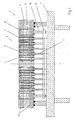
- FIG. 1 shows a mobile sliding table 1 and a press table 2 of a forming press not shown here.
- the sliding table 1 In the illustrated position, the sliding table 1 is moved into the forming press and lowered onto the press table 2.
- a die cushion 3 In the interior of the sliding table 1 is a die cushion 3. This die cushion 3 is fully integrated into the sliding table 1 and is also in a tool change together with the sliding table 1 out of the forming press, or driven into the forming press.
- the connecting plate 8 is connected at its outer ends in each case with a piston rod 10 and a piston 11 of a cylinder 12.
- the pressure pins 9 are retracted into the sliding table plate 4.
- the pressure pins 9 were displaced during the forming process by the movement of the plunger and the sheet holder down and are now in their lowest position.
- the force which is applied by the die cushion 3 during the forming process can be regulated via the cylinders 5, which in this case are designed as double-acting cylinders.
- each cylinder individually, as well as several cylinders can be controlled in combination. If several cylinders are controlled together, the cylinder chambers can be interconnected.
- the oil is supplied via horizontal holes 13.
- the die cushion 3 After the forming process, the die cushion 3 must be moved upwards again.
- piston 11 of the cylinder 12 is pressurized, so that the piston rods 10 are moved together with the connecting plate 8 upwards.
- the piston rods 7 of the cylinder 5 are taken from the connecting plate 8 in its upward movement. This ensures a synchronization of the piston rods 7 and causes the pressure pin 9 extend upward from the sliding table plate 4 and move the blank holder in its upper position.
- the connecting plate 8 leads in its downward movement ahead of the lower ends of the piston rods 7, so that no contact between the piston rods 7 and the connecting plate 8 is formed and a regulation of the blank holder forces by the cylinder 5 is possible.
- the arrangement of the cylinders 12 and 5 is variable and adaptable to the given requirements.
- the cylinders 5 are designed as single-acting cylinders.
- the connecting plate 8 would then penetrated in the downward movement of the piston 6 of the piston rods 7 and taken in the upward movement by a stop at the end of the piston rods 7 upwards.
- the cylinders 12 would then build up a back pressure in the upward movement of the cylinder 5 to ensure synchronization.
- This embodiment has the advantage that not all pressure pin 9 must be plugged because the cylinder 5 are designed to be single acting.
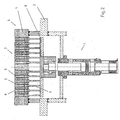
- FIG. 2 is another way to integrate die cushion functions into the sliding table. In this embodiment, not all die cushion functionalities, but only subfunctions are integrated into the sliding table 1.
- the cylinder 5 with the piston 6 and the piston rods 7 are constructed in their structure and in their function the same as described in the first embodiment. They serve the controlled introduction of force into the blank holder during the forming process.
- the connecting plate 8 is connected to a cylinder 8, which is located in the press table 2.
- the connecting plate 8 is thus no longer part of the sliding table 1, but of the press table 2 and thus remains even with a tool change and extending sliding table 1 in the forming press.
- the cylinder 14 performs substantially the same tasks as the cylinder 12 in the first embodiment.
- a plurality of cylinders can also be used to move the connecting plate 8 and thus the die cushion 3.
- the cylinder 5 can be designed so that the pressure pin 9 can not only be inserted centrally into the cylinder 5, but at different slots on the cylinder surface.
Abstract
Description
Die Erfindung betrifft eine Umformpresse gemaß dem Oberbegriff der Ansprüche 1 und 2, bei welcher die Ziehkissenfunktionalitäten oder Teile davon in einen oder mehrere Schiebetische integriert sind.The invention relates to a forming press according to the preamble of
Ziehkissen dienen der Niederhaltung beim Tiefziehen in Pressen. Sie verhindern damit die Falten- bzw. Rissbildung und heben durch die gleichzeitige Auswerferfunktion die Teile beim Stößelrücklauf auf Transportniveau. Das Werkstück wird zwischen einem speziellen Blechhalter und dem herab fahrenden Oberwerkzeug eingespannt. Dabei muss der vom Stößel während des Niedergangs aufgebrachten Kraft eine Gegenkraft über eine geregelt nachgebende Vorrichtung entgegenwirken. Bei konventionellen Ziehkissen wird die Gegenkraft auf den Blechhalter durch eine darunter liegende Druckwange aufgebracht. Der Aufbau eines solchen Ziehkissens ist im "
Charakteristisch für alle hydraulisch und pneumatisch betätigten Ziehkissen ist der sehr hohe Steuerungs- und Regelungsaufwand zur Erzielung der gewünschten Weg- und Kraftfunktionen.Characteristic of all hydraulically and pneumatically actuated die cushion is the very high control and regulatory effort to achieve the desired displacement and force functions.
In jüngster Zeit sind Ziehkissen bekannt geworden, bei denen diese Weg- und Kraftfunktionen von NC-gesteuerten elektrischen Antrieben erzeugt werden. Die ebenfalls gattungsgemäße
Sowohl die hydraulischen und pneumatischen, als auch die NC-gesteuerten elektrisch angetriebenen Ziehkissen wie sie im Stand der Technik beschrieben sind, werden im Bereich des Pressentisches angeordnet. Das heißt für die Regelung der Blechhalterkraft, dass diese für jedes neue Werkzeug neu eingestellt werden muss. Durch die Anordnung des Ziehkissens im Tisch ist es in der Regel auch nicht möglich bestehende Pressen ohne Ziehkissen mit einem solchen nachzurüsten. In der Regel sind die Bauräume in einem bestehenden Pressentisch für den Einbau eines Ziehkissens ungeeignet.Both the hydraulic and pneumatic, as well as the NC-controlled electrically driven die cushion as described in the prior art, are arranged in the region of the press table. That means for the regulation of the blank holder force, that this must be readjusted for each new tool. Due to the arrangement of the die cushion in the table, it is usually not possible to retrofit existing presses without die cushion with such. As a rule, the installation spaces in an existing press table are unsuitable for the installation of a die cushion.
Neueste Entwicklungen zielen darauf ab, die Ziehkissenfunktionalitäten in das Werkzeug zu verlagern. Diese Werkzeuge könnten in Verbindung mit einem so genannten segmentelastischen Blechhalter eingesetzt werden, welcher in einer pyramidenstumpfähnlichen Verrippung aufgebaut ist. In jeden Pyramidenstumpf können über jeweils zugeordnete Hydraulikzylinder und Proportional- oder Servoventile vorgebbare Niederhaltekräfte eingeleitet werden. Es ergibt sich somit eine in das Ziehwerkzeug integrierte Vielpunkt-Zieheinrichtung. Damit kann die Flächenpressung zwischen Blech und Blechhalter in einem bestimmten Blechhalterflächenelement eingestellt werden, ohne dass die Nachbarsegmente hierdurch wesentlich beeinflusst werden. (
Der Erfindung liegt die Aufgabe zugrunde ein Ziehkissen für eine Umformpresse zu entwickeln, welches im Aufbau kompakt und kostengünstig ist und welches für bestehende Pressen nachgerüstet werden kann.The invention has for its object to develop a die cushion for a forming press, which is compact and inexpensive in construction and which can be retrofitted for existing presses.
Diese Aufgabe wird ausgehend von einer Umformpresse nach den Oberbegriffen der Ansprüche 1 und 2 durch die kennzeichnenden Merkmale der Ansprüche 1 und 2 gelöst. In den Unteransprüchen sind vorteilhafte und zweckmäßige Weiterbildungen der erfindungsgemäßen Transportvorrichtung angegeben.This object is achieved on the basis of a forming press according to the preambles of
Der Erfindung liegt der Gedanke zugrunde, eine Umformpresse zu entwickeln, bei der die Ziehkissenfunktionalitäten ganz oder teilweise in einen Schiebetisch integriert werden. Die Integration des Ziehkissens in den Schiebetisch hat den Vorteil, dass bestehende Umformpressen, die bislang kein Ziehkissen haben, nachgerüstet werden können. Gleichzeitig hat dieses Schiebetischkissen gegenüber den im Stand der Technik beschriebenen Werkzeugen mit Ziehkissenfunktionalität einen deutlichen Kostenvorteil. Dieser Kostenvorteil liegt in der Tatsache begründet, dass nicht für jedes Werkzeug die entsprechenden Ziehkissenkomponenten zur Verfügung gestellt werden muss, sondern lediglich für einen oder zwei Schiebetische. In einer vorteilhaften Ausführung sind in einer Umformanlage zwei Schiebetische mit den erfindungsgemäßen Ziehvorrichtungen ausgestattet. Diese Ausführungsvariante hat den Vorteil, dass vor einem Werkzeugwechsel an dem außerhalb der Presse verbleibenden Schiebetisch mit dem erfindungsgemäßen Ziehkissen bereits vorbereitende Maßnahmen und Einstellungen durchgeführt werden können. Dies hat zur Folge, dass der Werkzeugwechsel sehr schnell durchgeführt werden kann und die Produktion mit den neuen Werkzeugen schnell wieder aufgenommen werden kann.The invention is based on the idea to develop a forming press, in which the die cushion functionalities are fully or partially integrated into a sliding table. The integration of the die cushion in the sliding table has the advantage that existing forming presses, which hitherto have no die cushion, can be retrofitted. At the same time, this sliding table cushion has a cushioning functionality with respect to tools described in the prior art significant cost advantage. This cost advantage is due to the fact that not for each tool the corresponding die cushion components must be provided, but only for one or two sliding tables. In an advantageous embodiment, two sliding tables are equipped with the drawing devices according to the invention in a forming system. This embodiment variant has the advantage that preparatory measures and adjustments can already be carried out before a tool change on the sliding table remaining outside the press with the die cushion according to the invention. As a result, the tool change can be performed very quickly and the production can be resumed quickly with the new tools.
Als Antriebe für das erfindungsgemäße Ziehkissen kommen prinzipiell alle bekannten Antriebsarten, wie zum Beispiel hydraulisch oder pneumatisch betätigte Zylinder, NC-Elektroantriebe oder Linearmotoren, in Frage.In principle, all known drive types, such as, for example, hydraulically or pneumatically actuated cylinders, NC electric drives or linear motors, come into question as drives for the die cushion according to the invention.
Eine weitere Ausführungsvariante der erfindungsgemäßen Ziehkissenvorrichtung besteht darin, dass Teilfunktionen des Ziehkissens sowohl im Schiebetisch als auch im Pressentisch angeordnet werden. So ist es beispielsweise denkbar, dass die Kraftfunktionen, welche während des Ziehvorganges wirksam sind im Schiebetisch, und die Wegfunktionen, welche außerhalb des Ziehvorganges wirksam sind im Pressentisch untergebracht werden.A further embodiment of the die cushion device according to the invention is that partial functions of the die cushion are arranged both in the sliding table and in the press table. So it is conceivable, for example, that the force functions that are effective during the drawing process in the sliding table, and the path functions that are effective outside of the drawing process are housed in the press table.
Eine weitere vorteilhafte Ausgestaltung des erfindungsgemäßen Ziehkissens besteht darin, dass die Druckbolzen, welche von den oben genannten Ziehkissenantrieben bewegt werden, direkt auf einen segmentelastischen Blechhalter wirken. Der Einsatz eines konventionellen Blechhalters ist aber ebenfalls möglich. Weitere Einzelheiten und Vorteile der Erfindung ergeben sich aus den nachfolgenden Beschreibungen der dargestellten Ausführungsbeispiele.A further advantageous embodiment of the die cushion according to the invention is that the pressure bolts, which are moved by the above-mentioned die cushion drives, directly act on a segment elastic sheet metal holder. The use of a conventional plate holder is also possible. Further details and advantages of the invention will become apparent from the following descriptions of the illustrated embodiments.
Es zeigen:
- Figur 1
- Schiebetisch einer Umformpresse mit integriertem Ziehkissen
Figur 2- Schiebetisch und Tisch einer Umformpresse mit Ziehkissen
- FIG. 1
- Sliding table of a forming press with integrated die cushion
- FIG. 2
- Sliding table and table of a forming press with die cushion
In diesem Ausführungsbeispiel wird eine Ausführungsform dargestellt, bei der hydraulische Komponenten im Ziehkissen zum Einsatz kommen. Wie bereits oben beschrieben sind aber auch alle im Stand der Technik bekannten Antriebsarten möglich. Während des Umformvorganges wird die Blechhaltekraft von den Zylindern 5 mit den Kolben 6 aufgebracht, welche sich innerhalb der Schiebetischplatte 4 befinden. Die Kolbestangen 7 ragen auf der Unterseite aus der Schiebtischplatte 4 heraus. An ihren freien Enden wird der Weg der Kolbenstangen 7 durch eine Verbindungsplatte 8 begrenzt. Die Kolbenstangen 7 und die Verbindungsplatte 8 sind nicht fest miteinander verbunden, es besteht lediglich ein Kontakt. Die Verbindungsplatte 8 bildet sozusagen einen Anschlag für die Kolbenstangen 7. Die Kraft-und Bewegungsübertragung der Kolben 6 auf den hier nicht dargestellten Blechhalter erfolgt über die Druckbolzen 9.In this embodiment, an embodiment is shown in which hydraulic components in the die cushion be used. As already described above, however, all types of drive known in the prior art are possible. During the forming process, the sheet holding force is applied by the
Die Verbindungsplatte 8 ist an ihren äußeren Enden jeweils mit einer Kolbenstange 10 und einem Kolben 11 eines Zylinders 12 verbunden.The connecting
In der dargestellten Position sind die Druckbolzen 9 in die Schiebetischplatte 4 eingefahren. Die Druckbolzen 9 wurden während des Umformvorganges durch die Bewegung des Stößels und des Blechhalters nach unten verdrängt und befinden sich nun in ihrer untersten Position. Die Kraft, welche während des Umformvorgangs vom Ziehkissen 3 aufgebracht wird, kann über die Zylinder 5, welche in diesem Fall als doppelt wirkende Zylinder ausgebildet sind, geregelt werden. Dabei kann sowohl jeder Zylinder einzeln, als auch mehrere Zylinder im Verbund geregelt werden. Werden mehrere Zylinder im Verbund geregelt, können die Zylinderräume miteinander verbunden werden. Die Ölversorgung erfolgt über horizontale Bohrungen 13.In the illustrated position, the
Nach dem Umformvorgang muss das Ziehkissen 3 wieder nach oben bewegt werden. Dazu werden Kolben 11 der Zylinder 12 mit Druck beaufschlagt, sodass die Kolbenstangen 10 zusammen mit der Verbindungsplatte 8 nach oben bewegt werden. Die Kolbenstangen 7 der Zylinder 5 werden von der Verbindungsplatte 8 in ihrer Aufwärtsbewegung mitgenommen. Dies gewährleistet einen Gleichlauf der Kolbenstangen 7 und führt dazu, dass die Druckbolzen 9 nach oben aus der Schiebtischplatte 4 ausfahren und den Blechhalter in seine obere Position bewegen. Während des Umformvorganges eilt die Verbindungsplatte 8 in ihrer Abwärtsbewegung den unteren Enden der Kolbenstangen 7 voraus, sodass kein Kontakt zwischen den Kolbenstangen 7 und der Verbindungsplatte 8 entsteht und eine Regelung der Blechhalterkräfte durch die Zylinder 5 möglich wird.After the forming process, the
Die Anordnung der Zylinder 12 und 5 ist variabel und auf die gegebenen Anforderungen anpassbar.The arrangement of the
Als Variante dieser Ausführungsform ist denkbar, dass die Zylinder 5 als einfach wirkende Zylinder ausgeführt werden. Die Verbindungsplatte 8 würde dann in der Abwärtsbewegung der Kolben 6 von den Kolbenstangen 7 durchdrungen und in der Aufwärtsbewegung durch einen Anschlag am Ende der Kolbenstangen 7 nach oben mitgenommen. Die Zylinder 12 würden dann bei der Aufwärtsbewegung der Zylinder 5 einen Gegendruck aufbauen um wiederum einen Gleichlauf zu gewährleisten.As a variant of this embodiment, it is conceivable that the
Diese Ausführungsvariante hat den Vorteil, dass nicht alle Druckbolzen 9 gesteckt werden müssen, weil die Zylinder 5 einfach wirkend ausgeführt sind.This embodiment has the advantage that not all
Bei Umformpressen, welche mit einem Schiebetisch mit geringer Bauhöhe ausgestattet sind und somit nicht genügend Bauraum für ein integriertes Ziehkissen vorhanden ist, besteht die Möglichkeit, den Schiebetisch mit einer größeren Höhe auszuführen und diesen dann im Pressentisch um die entsprechende Höhe automatisch versenkbar zu gestalten.In forming presses, which are equipped with a sliding table with a low height and thus not enough space for an integrated die cushion is available, it is possible to make the sliding table with a higher height and then make this in the press table to the appropriate height automatically retractable.
In
Die Zylinder 5 mit den Kolben 6 und den Kolbenstangen 7 sind in ihrem Aufbau und in ihrer Funktion gleich aufgebaut wie im ersten Ausführungsbeispiel beschrieben. Sie dienen der geregelten Krafteinleitung in den Blechhalter während des Umformvorganges.The
Die Verbindungsplatte 8 allerdings ist mit einem Zylinder 8 verbunden, welcher sich im Pressentisch 2 befindet. Die Verbindungsplatte 8 ist somit nicht mehr Bestandteil des Schiebetischs 1, sondern des Pressentischs 2 und verbleibt damit auch bei einem Werkzeugwechsel und ausfahrendem Schiebetisch 1 in der Umformpresse. Der Zylinder 14 erfüllt im Wesentlichen die gleichen Aufgaben, wie die Zylinder 12 im ersten Ausführungsbeispiel. Anstatt eines zentralen Zylinders 14 können ebenso mehrere Zylinder zum Verfahren der Verbindungsplatte 8 und somit des Ziehkissens 3 eingesetzt werden.However, the connecting
Die Erfindung ist nicht auf die beschriebenen und dargestellten Ausführungsbeispiele beschränkt. Sie umfasst auch alle fachmännischen Ausgestaltungen im Rahmen des erfinderischen Gedankens.The invention is not limited to the described and illustrated embodiments. It also includes all expert embodiments within the scope of the inventive idea.
Beispielsweise können anstatt der in den Ausführungsbeispielen beschriebenen Hydraulikzylinder auch andere aus dem Stand der Technik bekannte Antriebsarten verwendet werden, wie zum Beispiel elektrische Spindelantriebe, Linearmotoren oder Antriebe über Schwenkhebelmechanismen. Ebenso sind Kombinationen verschiedener Antriebe möglich.For example, instead of the hydraulic cylinder described in the embodiments, other from the prior Technically known drive types are used, such as electric spindle drives, linear motors or drives via pivoting lever mechanisms. Likewise, combinations of different drives are possible.
In einer weiteren vorteilhaften Ausgestaltung können die Zylinder 5 so gestaltet werden, dass die Druckbolzen 9 nicht nur mittig in den Zylinder 5 gesteckt werden können, sondern an verschiedenen Steckplätzen auf der Zylinderoberfläche.In a further advantageous embodiment, the
- 11
- Schiebetischsliding table
- 22
- Pressentischpress table
- 33
- Ziehkissencushion
- 44
- SchiebetischplatteSliding table
- 55
- Zylindercylinder
- 66
- Kolbenpiston
- 77
- Kolbenstangepiston rod
- 88th
- Verbindungsplatteconnecting plate
- 99
- Druckbolzenpushpin
- 1010
- Kolbenstangepiston rod
- 1111
- Kolbenpiston
- 1212
- Zylindercylinder
- 1313
- Bohrungdrilling
- 1414
- Zylindercylinder
Claims (15)
- Press, press working line, multi-ram press or the like with at least one drawing cushion device to control the plate holding force between the tool lower part and the tool upper part, and with at least one moveable sliding table, which, during a tool change, can be moved out of the press or moved into the press, characterised in that the drawing cushion device (3) with its drives (5, 12) and its movement and force transmission means is integrated in the moveable sliding table (1) and, together with the sliding table (1), can be moved out of the press and moved into the press.
- Press, press working line, multi-ram press or the like with at least one drawing cushion device to control the plate holding force between the tool lower part and the tool upper part, and with at least one moveable sliding table, which, during a tool change, can be moved out of the press or moved into the press, characterised in that the drives (5) and the movement and force transmission means, which produce a plate holding force during the forming process, are integrated in the moveable sliding table (1) and, together with the sliding table (1), can be moved out of the press and moved into the press.
- Press according to claim 1 and/or 2, characterised in that the drives (5) are integrated in the sliding table plate (4) and wherein in particular the drives (5) are configured as double-acting or single-acting hydraulic cylinders or wherein in particular the drives (5) are configured as electric spindle drives.
- Press according to any one or more of claims 1 to 3, characterised in that the drives (5) are configured from a combination of hydraulic drives or electric drives and a lever mechanism.
- Press according to any one or more of claims 1 to 4, characterised in that the plate holding force, which acts from the drawing cushion device (3) on the plate holder, is transmitted by insertable pressure bolts (9).
- Press according to any one or more of claims 1 to 5, characterised in that a driven connecting plate (8) is provided as a stop or entrainment device for the piston rod (7) to produce a synchronisation of all the drives (5) during the upward movement of the drawing cushion device (3).
- Press according to any one of claims 1 to 6, characterised in that one or more drives (12) are integrated in the sliding table plate (4) to move the connecting plate (8) or in that one or more drives (14) are preferably integrated in the press table (2) to move the connecting plate (8).
- Press according to any one or more of claims 1 to 7, characterised in that the drives (14) are configured as double-acting or single-acting hydraulic cylinders.
- Press according to any one or more of claims 1 to 8, characterised in that the drives (14) are configured as electric spindle drives.
- Press according to any one or more of claims 1 to 9, characterised in that the drives (14) are configured from a combination of hydraulic drives or electric drives and a lever mechanism.
- Press according to any one or more of claims 1 to 10, characterised in that the cylinders (5) are supplied with hydraulic fluid via bores (13) in the sliding table plate (4).
- Press according to any one or more of claims 1 to 11, characterised in that the drives (5) are controlled individually, independently of the other drives.
- Press according to any one or more of claims 1 to 12, characterised in that a plurality of the drives (5) are combined to form a control unit.
- Press according to any one or more of claims 1 to 13, characterised in that the pressure bolts (9) can be inserted at a plurality of insertion places on the upper side of the cylinder to transmit the plate holding force.
- Press according to any one or more of claims 1 to 14, characterised in that the sliding table (1) can be automatically lowered into the press table (2) after it has been moved into the tool space.
Applications Claiming Priority (2)
| Application Number | Priority Date | Filing Date | Title |
|---|---|---|---|
| DE200610057051 DE102006057051A1 (en) | 2006-11-30 | 2006-11-30 | Forming press with die cushion functionality integrated in the sliding table |
| PCT/DE2007/001717 WO2008064619A1 (en) | 2006-11-30 | 2007-09-22 | Forming press with a drawing cushion function integrated into the sliding table |
Publications (2)
| Publication Number | Publication Date |
|---|---|
| EP2114587A1 EP2114587A1 (en) | 2009-11-11 |
| EP2114587B1 true EP2114587B1 (en) | 2012-07-11 |
Family
ID=39232893
Family Applications (1)
| Application Number | Title | Priority Date | Filing Date |
|---|---|---|---|
| EP07846246A Not-in-force EP2114587B1 (en) | 2006-11-30 | 2007-09-22 | Forming press with a drawing cushion function integrated into the sliding table |
Country Status (5)
| Country | Link |
|---|---|
| EP (1) | EP2114587B1 (en) |
| CN (1) | CN101541447B (en) |
| DE (1) | DE102006057051A1 (en) |
| ES (1) | ES2391210T3 (en) |
| WO (1) | WO2008064619A1 (en) |
Families Citing this family (3)
| Publication number | Priority date | Publication date | Assignee | Title |
|---|---|---|---|---|
| CN101846106B (en) * | 2010-05-28 | 2012-10-17 | 南京航海仪器二厂有限公司 | Dynamic synchronous distributor of hydraulic oil cylinder |
| CN108869464B (en) * | 2018-08-02 | 2024-04-05 | 深圳领威科技有限公司 | Hydraulic device, hot chamber die casting machine and use method of hydraulic device |
| CN112275938A (en) * | 2020-11-25 | 2021-01-29 | 浙江旸谷科技有限公司 | Automatic change panel beating part material loading machine-shaping device |
Family Cites Families (6)
| Publication number | Priority date | Publication date | Assignee | Title |
|---|---|---|---|---|
| US3942354A (en) * | 1974-11-14 | 1976-03-09 | Dayton Progress Corporation | Die unit with quick change features |
| DE59002628D1 (en) | 1989-09-12 | 1993-10-14 | Mueller Weingarten Maschf | Mechanical or hydraulic press with drawing device or drawing stage of a step press. |
| EP0531141B1 (en) * | 1991-09-04 | 1995-03-22 | Toyota Jidosha Kabushiki Kaisha | Hydraulic cushioning system for press, having shut-off valve for disconnection of pressure-pin cylinders from power supply upon contact of movable die with workpiece |
| DE19821159A1 (en) | 1998-05-12 | 1999-11-25 | Johannes Huelshorst | Deep draw press |
| CN1351911A (en) * | 2001-12-11 | 2002-06-05 | 上海交通大学 | Single action deep drawing hydraulic test machine |
| JP4722558B2 (en) * | 2004-06-01 | 2011-07-13 | 株式会社小松製作所 | Die cushion device |
-
2006
- 2006-11-30 DE DE200610057051 patent/DE102006057051A1/en not_active Withdrawn
-
2007
- 2007-09-22 ES ES07846246T patent/ES2391210T3/en active Active
- 2007-09-22 CN CN2007800425122A patent/CN101541447B/en not_active Expired - Fee Related
- 2007-09-22 EP EP07846246A patent/EP2114587B1/en not_active Not-in-force
- 2007-09-22 WO PCT/DE2007/001717 patent/WO2008064619A1/en active Application Filing
Also Published As
| Publication number | Publication date |
|---|---|
| DE102006057051A1 (en) | 2008-07-03 |
| CN101541447A (en) | 2009-09-23 |
| CN101541447B (en) | 2012-06-13 |
| ES2391210T3 (en) | 2012-11-22 |
| EP2114587A1 (en) | 2009-11-11 |
| WO2008064619A1 (en) | 2008-06-05 |
Similar Documents
| Publication | Publication Date | Title |
|---|---|---|
| EP0418779B1 (en) | Method for manufacture of workpieces by punching, in particular in a precision counter punching tool | |
| EP2509725B1 (en) | Radial press | |
| DE102011011013B4 (en) | Press plant for forming or processing metal components | |
| DE3008947A1 (en) | MECHANICAL PRESS | |
| DE102015004108A1 (en) | Forming process and press | |
| DE2830779C2 (en) | Hydraulic double pressure press | |
| EP1063028B2 (en) | Press for external hydroforming | |
| EP3160726B1 (en) | Improved c-frame press | |
| EP2114587B1 (en) | Forming press with a drawing cushion function integrated into the sliding table | |
| DE2033106A1 (en) | Upsetting or forging press | |
| EP1252010B1 (en) | Press | |
| DE102006019207B4 (en) | Drive system of a multi-tappet forming press | |
| DE8021267U1 (en) | LOAD BALANCING DEVICE FOR PRESS TOOLS | |
| DE60219717T2 (en) | Device for carrying out a high pressure forming process | |
| DE19822436A1 (en) | Operating hydraulic press the force drop during changeover from the fast motion to the forming motion is reduced | |
| EP3056291A1 (en) | Press with cutting shock damping | |
| WO2005021253A2 (en) | Hydraulic press and deep-drawing press | |
| DE102014111683A1 (en) | Press drive for a forming device | |
| DE19611611A1 (en) | Machine press | |
| DE10117578B4 (en) | drawing press | |
| EP3024646B1 (en) | Force module and modular press system | |
| EP0635320B1 (en) | Pressure pad for single-acting presses in particular for mechanical and transfer presses | |
| WO1999054123A1 (en) | Method for operating a hydraulic press | |
| DE10215003A1 (en) | Hydraulic press used for deep drawing operations has press body connected to two columns in each of three piston and cylinder assemblies | |
| DE19607257C2 (en) | Hydraulic sheet metal press |
Legal Events
| Date | Code | Title | Description |
|---|---|---|---|
| PUAI | Public reference made under article 153(3) epc to a published international application that has entered the european phase |
Free format text: ORIGINAL CODE: 0009012 |
|
| 17P | Request for examination filed |
Effective date: 20090408 |
|
| AK | Designated contracting states |
Kind code of ref document: A1 Designated state(s): AT BE BG CH CY CZ DE DK EE ES FI FR GB GR HU IE IS IT LI LT LU LV MC MT NL PL PT RO SE SI SK TR |
|
| 17Q | First examination report despatched |
Effective date: 20091111 |
|
| DAX | Request for extension of the european patent (deleted) | ||
| GRAP | Despatch of communication of intention to grant a patent |
Free format text: ORIGINAL CODE: EPIDOSNIGR1 |
|
| GRAS | Grant fee paid |
Free format text: ORIGINAL CODE: EPIDOSNIGR3 |
|
| GRAA | (expected) grant |
Free format text: ORIGINAL CODE: 0009210 |
|
| AK | Designated contracting states |
Kind code of ref document: B1 Designated state(s): AT BE BG CH CY CZ DE DK EE ES FI FR GB GR HU IE IS IT LI LT LU LV MC MT NL PL PT RO SE SI SK TR |
|
| REG | Reference to a national code |
Ref country code: GB Ref legal event code: FG4D Free format text: NOT ENGLISH |
|
| REG | Reference to a national code |
Ref country code: CH Ref legal event code: EP |
|
| REG | Reference to a national code |
Ref country code: AT Ref legal event code: REF Ref document number: 565825 Country of ref document: AT Kind code of ref document: T Effective date: 20120715 |
|
| REG | Reference to a national code |
Ref country code: IE Ref legal event code: FG4D Free format text: LANGUAGE OF EP DOCUMENT: GERMAN |
|
| REG | Reference to a national code |
Ref country code: DE Ref legal event code: R096 Ref document number: 502007010220 Country of ref document: DE Effective date: 20120906 |
|
| REG | Reference to a national code |
Ref country code: ES Ref legal event code: FG2A Ref document number: 2391210 Country of ref document: ES Kind code of ref document: T3 Effective date: 20121122 |
|
| REG | Reference to a national code |
Ref country code: NL Ref legal event code: VDEP Effective date: 20120711 |
|
| REG | Reference to a national code |
Ref country code: LT Ref legal event code: MG4D Effective date: 20120711 |
|
| PG25 | Lapsed in a contracting state [announced via postgrant information from national office to epo] |
Ref country code: FI Free format text: LAPSE BECAUSE OF FAILURE TO SUBMIT A TRANSLATION OF THE DESCRIPTION OR TO PAY THE FEE WITHIN THE PRESCRIBED TIME-LIMIT Effective date: 20120711 Ref country code: IS Free format text: LAPSE BECAUSE OF FAILURE TO SUBMIT A TRANSLATION OF THE DESCRIPTION OR TO PAY THE FEE WITHIN THE PRESCRIBED TIME-LIMIT Effective date: 20121111 Ref country code: LT Free format text: LAPSE BECAUSE OF FAILURE TO SUBMIT A TRANSLATION OF THE DESCRIPTION OR TO PAY THE FEE WITHIN THE PRESCRIBED TIME-LIMIT Effective date: 20120711 Ref country code: CY Free format text: LAPSE BECAUSE OF FAILURE TO SUBMIT A TRANSLATION OF THE DESCRIPTION OR TO PAY THE FEE WITHIN THE PRESCRIBED TIME-LIMIT Effective date: 20120711 |
|
| PG25 | Lapsed in a contracting state [announced via postgrant information from national office to epo] |
Ref country code: GR Free format text: LAPSE BECAUSE OF FAILURE TO SUBMIT A TRANSLATION OF THE DESCRIPTION OR TO PAY THE FEE WITHIN THE PRESCRIBED TIME-LIMIT Effective date: 20121012 Ref country code: LV Free format text: LAPSE BECAUSE OF FAILURE TO SUBMIT A TRANSLATION OF THE DESCRIPTION OR TO PAY THE FEE WITHIN THE PRESCRIBED TIME-LIMIT Effective date: 20120711 Ref country code: PT Free format text: LAPSE BECAUSE OF FAILURE TO SUBMIT A TRANSLATION OF THE DESCRIPTION OR TO PAY THE FEE WITHIN THE PRESCRIBED TIME-LIMIT Effective date: 20121112 Ref country code: SI Free format text: LAPSE BECAUSE OF FAILURE TO SUBMIT A TRANSLATION OF THE DESCRIPTION OR TO PAY THE FEE WITHIN THE PRESCRIBED TIME-LIMIT Effective date: 20120711 Ref country code: SE Free format text: LAPSE BECAUSE OF FAILURE TO SUBMIT A TRANSLATION OF THE DESCRIPTION OR TO PAY THE FEE WITHIN THE PRESCRIBED TIME-LIMIT Effective date: 20120711 Ref country code: PL Free format text: LAPSE BECAUSE OF FAILURE TO SUBMIT A TRANSLATION OF THE DESCRIPTION OR TO PAY THE FEE WITHIN THE PRESCRIBED TIME-LIMIT Effective date: 20120711 |
|
| PG25 | Lapsed in a contracting state [announced via postgrant information from national office to epo] |
Ref country code: NL Free format text: LAPSE BECAUSE OF FAILURE TO SUBMIT A TRANSLATION OF THE DESCRIPTION OR TO PAY THE FEE WITHIN THE PRESCRIBED TIME-LIMIT Effective date: 20120711 |
|
| BERE | Be: lapsed |
Owner name: MULLER WEINGARTEN A.G. Effective date: 20120930 |
|
| PG25 | Lapsed in a contracting state [announced via postgrant information from national office to epo] |
Ref country code: MC Free format text: LAPSE BECAUSE OF NON-PAYMENT OF DUE FEES Effective date: 20120930 Ref country code: RO Free format text: LAPSE BECAUSE OF FAILURE TO SUBMIT A TRANSLATION OF THE DESCRIPTION OR TO PAY THE FEE WITHIN THE PRESCRIBED TIME-LIMIT Effective date: 20120711 Ref country code: EE Free format text: LAPSE BECAUSE OF FAILURE TO SUBMIT A TRANSLATION OF THE DESCRIPTION OR TO PAY THE FEE WITHIN THE PRESCRIBED TIME-LIMIT Effective date: 20120711 Ref country code: CZ Free format text: LAPSE BECAUSE OF FAILURE TO SUBMIT A TRANSLATION OF THE DESCRIPTION OR TO PAY THE FEE WITHIN THE PRESCRIBED TIME-LIMIT Effective date: 20120711 Ref country code: DK Free format text: LAPSE BECAUSE OF FAILURE TO SUBMIT A TRANSLATION OF THE DESCRIPTION OR TO PAY THE FEE WITHIN THE PRESCRIBED TIME-LIMIT Effective date: 20120711 |
|
| REG | Reference to a national code |
Ref country code: CH Ref legal event code: PL |
|
| PLBE | No opposition filed within time limit |
Free format text: ORIGINAL CODE: 0009261 |
|
| STAA | Information on the status of an ep patent application or granted ep patent |
Free format text: STATUS: NO OPPOSITION FILED WITHIN TIME LIMIT |
|
| PG25 | Lapsed in a contracting state [announced via postgrant information from national office to epo] |
Ref country code: SK Free format text: LAPSE BECAUSE OF FAILURE TO SUBMIT A TRANSLATION OF THE DESCRIPTION OR TO PAY THE FEE WITHIN THE PRESCRIBED TIME-LIMIT Effective date: 20120711 |
|
| 26N | No opposition filed |
Effective date: 20130412 |
|
| REG | Reference to a national code |
Ref country code: IE Ref legal event code: MM4A |
|
| GBPC | Gb: european patent ceased through non-payment of renewal fee |
Effective date: 20121011 |
|
| REG | Reference to a national code |
Ref country code: FR Ref legal event code: ST Effective date: 20130531 |
|
| PG25 | Lapsed in a contracting state [announced via postgrant information from national office to epo] |
Ref country code: BE Free format text: LAPSE BECAUSE OF NON-PAYMENT OF DUE FEES Effective date: 20120930 Ref country code: CH Free format text: LAPSE BECAUSE OF NON-PAYMENT OF DUE FEES Effective date: 20120930 Ref country code: LI Free format text: LAPSE BECAUSE OF NON-PAYMENT OF DUE FEES Effective date: 20120930 Ref country code: BG Free format text: LAPSE BECAUSE OF FAILURE TO SUBMIT A TRANSLATION OF THE DESCRIPTION OR TO PAY THE FEE WITHIN THE PRESCRIBED TIME-LIMIT Effective date: 20121011 Ref country code: IE Free format text: LAPSE BECAUSE OF NON-PAYMENT OF DUE FEES Effective date: 20120922 Ref country code: GB Free format text: LAPSE BECAUSE OF NON-PAYMENT OF DUE FEES Effective date: 20121011 |
|
| REG | Reference to a national code |
Ref country code: DE Ref legal event code: R097 Ref document number: 502007010220 Country of ref document: DE Effective date: 20130412 |
|
| PG25 | Lapsed in a contracting state [announced via postgrant information from national office to epo] |
Ref country code: FR Free format text: LAPSE BECAUSE OF NON-PAYMENT OF DUE FEES Effective date: 20121001 |
|
| REG | Reference to a national code |
Ref country code: AT Ref legal event code: MM01 Ref document number: 565825 Country of ref document: AT Kind code of ref document: T Effective date: 20120922 |
|
| PG25 | Lapsed in a contracting state [announced via postgrant information from national office to epo] |
Ref country code: MT Free format text: LAPSE BECAUSE OF FAILURE TO SUBMIT A TRANSLATION OF THE DESCRIPTION OR TO PAY THE FEE WITHIN THE PRESCRIBED TIME-LIMIT Effective date: 20120711 |
|
| PG25 | Lapsed in a contracting state [announced via postgrant information from national office to epo] |
Ref country code: AT Free format text: LAPSE BECAUSE OF NON-PAYMENT OF DUE FEES Effective date: 20120922 |
|
| PG25 | Lapsed in a contracting state [announced via postgrant information from national office to epo] |
Ref country code: TR Free format text: LAPSE BECAUSE OF FAILURE TO SUBMIT A TRANSLATION OF THE DESCRIPTION OR TO PAY THE FEE WITHIN THE PRESCRIBED TIME-LIMIT Effective date: 20120711 |
|
| PG25 | Lapsed in a contracting state [announced via postgrant information from national office to epo] |
Ref country code: LU Free format text: LAPSE BECAUSE OF NON-PAYMENT OF DUE FEES Effective date: 20120922 |
|
| PG25 | Lapsed in a contracting state [announced via postgrant information from national office to epo] |
Ref country code: HU Free format text: LAPSE BECAUSE OF FAILURE TO SUBMIT A TRANSLATION OF THE DESCRIPTION OR TO PAY THE FEE WITHIN THE PRESCRIBED TIME-LIMIT Effective date: 20070922 |
|
| PGFP | Annual fee paid to national office [announced via postgrant information from national office to epo] |
Ref country code: ES Payment date: 20150923 Year of fee payment: 9 Ref country code: DE Payment date: 20150901 Year of fee payment: 9 |
|
| PGFP | Annual fee paid to national office [announced via postgrant information from national office to epo] |
Ref country code: IT Payment date: 20150925 Year of fee payment: 9 |
|
| REG | Reference to a national code |
Ref country code: DE Ref legal event code: R119 Ref document number: 502007010220 Country of ref document: DE |
|
| PG25 | Lapsed in a contracting state [announced via postgrant information from national office to epo] |
Ref country code: DE Free format text: LAPSE BECAUSE OF NON-PAYMENT OF DUE FEES Effective date: 20170401 |
|
| PG25 | Lapsed in a contracting state [announced via postgrant information from national office to epo] |
Ref country code: IT Free format text: LAPSE BECAUSE OF NON-PAYMENT OF DUE FEES Effective date: 20160922 |
|
| PG25 | Lapsed in a contracting state [announced via postgrant information from national office to epo] |
Ref country code: ES Free format text: LAPSE BECAUSE OF NON-PAYMENT OF DUE FEES Effective date: 20160923 |
|
| REG | Reference to a national code |
Ref country code: ES Ref legal event code: FD2A Effective date: 20181126 |