EP2329189B1 - Brennstoffdüse - Google Patents
Brennstoffdüse Download PDFInfo
- Publication number
- EP2329189B1 EP2329189B1 EP09783434.5A EP09783434A EP2329189B1 EP 2329189 B1 EP2329189 B1 EP 2329189B1 EP 09783434 A EP09783434 A EP 09783434A EP 2329189 B1 EP2329189 B1 EP 2329189B1
- Authority
- EP
- European Patent Office
- Prior art keywords
- fuel
- nozzle
- synthesis gas
- flower
- flow
- Prior art date
- Legal status (The legal status is an assumption and is not a legal conclusion. Google has not performed a legal analysis and makes no representation as to the accuracy of the status listed.)
- Not-in-force
Links
Images


Classifications
-
- F—MECHANICAL ENGINEERING; LIGHTING; HEATING; WEAPONS; BLASTING
- F23—COMBUSTION APPARATUS; COMBUSTION PROCESSES
- F23D—BURNERS
- F23D14/00—Burners for combustion of a gas, e.g. of a gas stored under pressure as a liquid
- F23D14/20—Non-premix gas burners, i.e. in which gaseous fuel is mixed with combustion air on arrival at the combustion zone
- F23D14/22—Non-premix gas burners, i.e. in which gaseous fuel is mixed with combustion air on arrival at the combustion zone with separate air and gas feed ducts, e.g. with ducts running parallel or crossing each other
-
- F—MECHANICAL ENGINEERING; LIGHTING; HEATING; WEAPONS; BLASTING
- F23—COMBUSTION APPARATUS; COMBUSTION PROCESSES
- F23D—BURNERS
- F23D14/00—Burners for combustion of a gas, e.g. of a gas stored under pressure as a liquid
- F23D14/46—Details, e.g. noise reduction means
- F23D14/48—Nozzles
- F23D14/58—Nozzles characterised by the shape or arrangement of the outlet or outlets from the nozzle, e.g. of annular configuration
-
- F—MECHANICAL ENGINEERING; LIGHTING; HEATING; WEAPONS; BLASTING
- F23—COMBUSTION APPARATUS; COMBUSTION PROCESSES
- F23R—GENERATING COMBUSTION PRODUCTS OF HIGH PRESSURE OR HIGH VELOCITY, e.g. GAS-TURBINE COMBUSTION CHAMBERS
- F23R3/00—Continuous combustion chambers using liquid or gaseous fuel
- F23R3/28—Continuous combustion chambers using liquid or gaseous fuel characterised by the fuel supply
Definitions
- the invention relates to a fuel nozzle, comprising a nozzle tube and a nozzle outlet opening, wherein the nozzle tube is in communication with a fuel supply line for supplying a fuel into the nozzle tube, wherein the fuel from the nozzle outlet opening is injected into an air flow, which surrounds the fuel nozzle substantially annular , And a reaching to the nozzle outlet opening first nozzle tube section is formed flower-shaped in such a way that a substantially coaxial injection of the fuel in the air flow is feasible, wherein the nozzle outlet opening has a closed, conical flower scar.
- a fuel nozzle is for example from the document JP 8 145 361 A known.
- synthesis gas can in principle be made from solid, liquid and gaseous educts.
- synthesis gas can in principle be made from solid, liquid and gaseous educts.
- coal gasification biomass gasification
- coke gasification
- premix combustion is becoming increasingly important also in the combustion of low calorific gases.
- Premix burners typically include a premix zone in which air and fuel are mixed before passing the mixture into a combustion chamber. There, the mixture burns, producing a hot gas under elevated pressure. This hot gas is forwarded to the turbine. In connection with the operation of Vormischbrennern it comes Above all, it is important to keep the nitrogen oxide emissions low and to avoid a flashback.
- Synthesis gas premix burners are characterized by the fact that synthesis gases are used as fuel in them. Compared with the traditional turbine fuels natural gas and petroleum, which consist essentially of hydrocarbon compounds, the combustible components of the synthesis gas are essentially carbon monoxide and hydrogen. Depending on the gasification process and the overall plant concept, the calorific value of the synthesis gas is about 5 to 10 times smaller than that of natural gas.
- the quality of mixing between synthesis gas and combustion air at the flame front is an important influencing variable for avoiding temperature peaks and thus for minimizing the formation of thermal nitrogen oxides.
- a spatially good mixture of combustion air and synthesis gas is particularly difficult due to the high volume flows of required synthesis gas and the correspondingly large spatial extent of the mixing area.
- the lowest possible production of nitrogen oxides is an essential requirement for combustion, in particular for combustion in the gas turbine plant of a power plant.
- the formation of nitrogen oxides increases exponentially rapidly with the combustion flame temperature. In an inhomogeneous mixture of fuel and air results in a certain distribution of flame temperatures in the combustion area. The maximum temperature of such a distribution determined by the said exponential relationship of nitrogen oxide formation and flame temperature significantly the amount of undesirable nitrogen oxides formed.
- the object of the invention is to provide a fuel nozzle, in particular for the supply of synthesis gas, which leads to a lower nitrogen oxide formation during combustion.
- a fuel nozzle comprising a nozzle tube and a nozzle outlet opening, wherein the nozzle tube is in communication with a fuel supply line for supplying a fuel into the nozzle tube, wherein the fuel from the nozzle outlet opening in an air flow, which the fuel nozzle substantially annular surrounds, is injected, and a reaching to the nozzle outlet opening first nozzle tube section is shaped like a flower in such a way that a substantially coaxial injection of the fuel in the air flow is feasible, wherein the nozzle outlet opening has a closed, conical flower scar.
- the invention is based on the fact that, especially for large volume flows of fuel such as synthesis gas, large injection sequences must be made available, which is associated with high pressure losses. Furthermore, however, in order to achieve good NOx values, especially the premix mode with a good mixing is necessary. However, the swirling elements used in the prior art and the inflow of the fuel stream transverse to the air flow lead to a significantly undesirable pressure loss, which in turn leads to poor NOx values.
- the invention is based on the recognition that an increase in the contact area between the synthesis gas stream causes a significant improvement in the mixing. This effect is particularly important if the fuel flow and the air flow have different flow velocity. Due to the flower-shaped design of first nozzle pipe section this is caused. Due to the flower-shaped configuration of the first nozzle pipe section, a second flow field, ie desired calculable turbulences, is additionally formed on the profile trailing edges, which in turn improves mixing. This is also particularly advantageous if the fuel flow and the air flow have different flow velocity.
- the flower-shaped embodiment according to the invention of the first nozzle tube section further enables coaxial injection of the fuel into the air flow. As a result, undesirably high pressure losses are avoided. This allows operation of the nozzle in the premix mode, even at high volume flows of fuel, such as this is the case with synthesis gas.
- the nozzle outlet opening of the fuel nozzle has a closed, conical flower scar.
- the flower scar which is arranged symmetrically around the center of the designed as a flower nozzle orifice, a continuous area mixing of the fuel and the air is enforced. This is especially for the fuel, which would be passed through the central region of the nozzle exit opening, an advantage.
- Due to the design of the nozzle outlet opening with a flower hub quasi the contact surface between fuel and air is further increased, which has a positive effect on the mixing. However, it is still possible coaxial inflow of the fuel into the air flow, whereby only a negligible pressure loss arises despite the improved mixing.
- the flower scar runs in the direction of flow sharp.
- the flower scar is double-conical.
- boundary layer separation can be avoided and reduce the risk of flashback by return areas.
- the flower scar has notches. These indentations are applied to the flower scar in correspondence with the individual petals or in correspondence with the profile trailing edges. These notches essentially serve to provide a smooth passage for the fuel, i. the exit of the fuel from the fuel nozzle takes place without unwanted and unpredictable Verwirblept. Thus, boundary layer separation can be avoided and the risk of flashback by return areas can be reduced.
- the notches are applied in a straight line in the direction of flow and / or twisted.
- a swirl during the injection can be impressed on the air flow or the fuel flow.
- the first nozzle pipe section preferably tapers in the flow direction. As a result, an increase in the flow rate of the fuel is achieved.
- the flower shape of the first nozzle tube section is sawtooth-like. Predictable turbulences are formed in the flow field by the saw teeth, which causes a better mixing of the fuel with the air flow. However, since coaxial injection continues to be assured, no increase in pressure loss occurs in this embodiment of the fuel nozzle.
- a second nozzle tube section may be present, to which the first nozzle tube section adjoins in the flow direction, wherein the second nozzle tube section tapers in the flow direction.
- the sawtooth-like first nozzle tube section connects in the horizontal direction to the second nozzle tube section.
- the sawtooth-like first nozzle tube section adjoins the second nozzle tube section inclined relative to the horizon. This increases the flow rate of the fuel.
- the flower scar is connected to a tube extending substantially coaxially to the nozzle tube for the supply of high-calorie fuel and has at least one tangential and / or axial inlet opening.
- the arrangement, the number, and the diameter of the inlet openings can vary. Since the high calorie fuel feed within the synthesis gas feed (high calorie fuel feed is annularly surrounded by the synthesis gas feed), these are preferably tangential and axial inlet ports, i. Holes.
- both the inlet openings for high-calorie fuel and the feed itself only require a small diameter, since the volume flow of the high-calorie fuel is substantially lower than that of the synthesis gas. This fact contributes to the supply of high calorific fuel causing little or no disturbance in the air stream during synthesis gas operation.
- the at least one tangential inlet opening is arranged on the flower web between two petals of the flower-shaped synthesis gas injection.
- the fuel nozzle is present in a burner.
- a burner This is in particular a synthesis gas burner operated in a premix mode.
- the burner can be designed as a two- or multi-fuel burner, which can also be operated with, for example, natural gas in Vormischmodus.
- the burner is present in a gas turbine.
- the synthesis gas can in principle be made from solid, liquid and gaseous educts.
- the coal gasification should be mentioned.
- Coal is converted in a mixture of partial oxidation and gasification with water vapor to a mixture of CO and hydrogen.
- the use of other solids such as biomass and coke should be mentioned in principle.
- Different crude oil distillates can be used as the liquid reactants for synthesis gas.
- the most important gaseous educt is natural gas.
- Fig. 1 shows a fuel nozzle. This has a nozzle tube 2 and a nozzle outlet opening 10.
- the nozzle tube 2 is in communication with a fuel supply line (not shown) which supplies fuel to the nozzle tube 2.
- the fuel is injected from the nozzle outlet opening 10 into an air stream 8, which surrounds the fuel nozzle in an annular manner.
- the reaching up to the nozzle outlet opening 10 first nozzle pipe section 4 is shaped like a flower 6 in such a way that a substantially coaxial injection of the fuel in the air stream 4 is feasible.
- the synthesis gas is guided inside the nozzle tube 2.
- Fig. 2 shows a cross section of such a nozzle outlet opening 10 with six individual flowers.
- the number of flowers is mainly dependent on the individual burner types or gas turbine types and may vary.
- the nozzle tube section 4 and the nozzle outlet opening 10 provide by their flower-shaped configuration 6 a larger contact area between the synthesis gas stream and air stream 8 ago.
- This embodiment is particularly advantageous if the air stream 8 and the synthesis gas stream have different flow velocities.
- this flower-shaped embodiment 6 has the significant advantage that a second flow field is formed, in particular at the profile trailing edges of the individual flowers. Here vortex structures are formed. This also contributes significantly to improving the mixing, especially when there is a significant difference in the flow rates of the synthesis gas and the air stream 8.
- Fig. 3 shows by way of example as a diagram, the improved interference of a flower-shaped fuel nozzle, here in the FIG. 3 indicated at b, as compared to a fuel nozzle, here for example an annular, tapered nozzle tube according to the prior art (in FIG. 3 indicated with a).
- the non-mixing degree is indicated on the y-axis.
- the flower-shaped fuel nozzle has a higher mixing, but due to the coaxial injection with lower pressure loss.
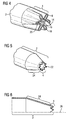
- Fig. 4 shows an embodiment of a fuel nozzle according to the invention. This has at the flower-shaped nozzle outlet opening 10 centrally a conical flower scar 14. According to the invention the flower scar 14 is formed doppelkonisch. This has the advantage of being a smooth transition of the two streams is ensured. Furthermore, this embodiment prevents a boundary layer separation or the formation of return flow areas, which can cause a flashback.
- notches 16 may be mounted in the conical flower scar. These are advantageously on the one hand in their radial extension and attachment in accordance with the individual flowers attached, that is, the notch 16 and the flowers face each other. This achieves a smooth exit surface for the synthesis gas. On the other hand, further indentations 16 are provided, which lie opposite the profile trailing edges 20 and in their radial width essentially coincide with them. These achieve a smooth exit surface for the air flow 8.
- the notches 16 may be rectilinear in the flow direction or wound so as to achieve a turbulence of the air or the fuel.
- Fig. 5 shows an alternative fuel nozzle which is not part of the invention, in which the flower form has 8 tapered flowers, that is formed substantially sawtooth-like.
- these saw teeth 22 are attached to a first pipe section 4.
- This first pipe section 4 may have a constant pipe diameter in the flow direction (ie, the saw teeth 22 are substantially horizontal) or may be tapered in the flow direction (ie, the saw teeth 22 are inclined to the horizon line 26, Fig. 6 ).
- a second pipe section 24, to which the first pipe section 4 adjoins in the flow direction, can be tapered in the direction of flow for better injection.
- the design of the fuel nozzle with saw teeth 22 desired turbulence in the flow field to be generated, which in turn improves the mixing between synthesis gas and air stream 8.
- Fig. 7 is an embodiment of the fuel nozzle with a second fuel supply shown, which is not part of the invention. Since the synthesis gas inlet openings must ensure a large volume flow, the fuel nozzle is formed in the shape of a flower 6 in relation to the synthesis gas.
- Tangential natural gas inlet openings 16 are placed between two petals 18.
- the point of contact or the line of contact of two petals 18 with each other is referred to below as flower spike 19.
- Fig. 7 has six tangential natural gas inlet openings 16 and an axial natural gas inlet openings 17. Depending on the burner and gas turbine, both the number and the arrangement may vary.
- the natural gas inlet openings 16, 17 are essentially round, and can be produced by means of bores.
- the syngas feed and its flower-shaped syngas inlet opening 6 as well as the natural gas supply 30 with the natural gas inlet 16,17 are designed so that a pressure drop below 25 dp / p is achieved with the same heat input with respect to synthesis and natural gas.
- Fig. 8 schematically shows the natural gas supply 30. Since the volume flow of natural gas is much lower than that for synthesis gas, the diameter of the natural gas supply 30 is substantially lower than the synthesis gas supply. In order to switch from synthesis gas to natural gas operation or vice versa, it is only necessary to interrupt the synthesis gas or natural gas supply 30. This can be achieved without hardware changes.
- any other high-calorie burner material can be used, for example fuel oil.
- the flower shape 6 of the synthesis gas inlet port is merely an example, other forms for syngas inlet port are also conceivable.
- synthesis gas burners should be operable not only with a fuel, but possibly with different fuels, such as oil, natural gas and / or coal gas optional or even in combination to increase security of supply and flexibility in operation.
- synthesis gas burners should be operable not only with a fuel, but possibly with different fuels, such as oil, natural gas and / or coal gas optional or even in combination to increase security of supply and flexibility in operation.
- this invention it is possible to use the same nozzle for natural gas (or diluted natural gas) or synthesis gas. This simplifies the design of the burner and significantly reduces component components.
- the fuel nozzle presented here is not limited only to the operation with synthesis gas, but it can be operated advantageously with any fuel. This To emphasize the advantage especially with volume-rich fuel flow.
- the fuel nozzle according to the invention is particularly suitable in premix operation.
Landscapes
- Engineering & Computer Science (AREA)
- Chemical & Material Sciences (AREA)
- Combustion & Propulsion (AREA)
- Mechanical Engineering (AREA)
- General Engineering & Computer Science (AREA)
- Gas Burners (AREA)
- Nozzles For Spraying Of Liquid Fuel (AREA)
Description
- Die Erfindung betrifft eine Brennstoffdüse, umfassend ein Düsenrohr und eine Düsenaustrittsöffnung, wobei das Düsenrohr mit einer Brennstoffzufuhrleitung in Verbindung steht zum Zuführen eines Brennstoffs in das Düsenrohr, wobei der Brennstoff aus der Düsenaustrittsöffnung in einen Luftstrom, welcher die Brennstoffdüse im Wesentlichen ringförmig umgibt, eingedüst wird, und ein bis zur Düsenaustrittsöffnung reichender erster Düsenrohrabschnitt blütenförmig ausgebildet ist und zwar dergestalt, dass eine im wesentlichen koaxiale Eindüsung des Brennstoffs in den Luftstrom durchführbar ist, wobei die Düsenaustrittsöffnung eine geschlossene, konisch ausgebildete Blütennarbe aufweiset. Eine solche Brennstoffdüse ist zum Beispiel aus dem Dokument
JP 8 145 361 A - Der Preisanstieg von Erdgas macht die Weiterentwicklung von alternativen Brennstoffen notwendig. Dies ist beispielsweise niederkalorisches Brenngas nachfolgend auch als Synthesegas bezeichnet. Die Herstellung von Synthesegas kann prinzipiell aus festen, flüssigen und gasförmigen Edukten erfolgen. Bei der Herstellung von Synthesegas aus festen Edukten ist vor allem die Kohlevergasung, Biomassenvergasung und die Koksvergasung zu nennen.
- Im Hinblick auf zunehmend strengere Anforderungen an den Ausstoß von Stickoxiden gewinnt die Vormischverbrennung auch bei der Verbrennung von niederkalorischen Gasen zunehmend an Bedeutung.
- Vormischbrenner umfassen typischerweise eine Vormischzone, in der Luft und Brennstoff vermischt werden, bevor das Gemisch in eine Brennkammer geleitet wird. Dort verbrennt das Gemisch, wobei ein unter erhöhtem Druck stehendes Heißgas erzeugt wird. Dieses Heißgas wird zur Turbine weitergeleitet. Im Zusammenhang mit dem Betrieb von Vormischbrennern kommt es vor allem darauf an, die Stickoxidemissionen gering zu halten und einen Flammenrückschlag zu vermeiden.
- Synthesegas-Vormischbrenner zeichnen sich dadurch aus, dass in ihnen Synthesegase als Brennstoff verwendet werden. Verglichen mit den klassischen Turbinenbrennstoffen Erdgas und Erdöl, die im Wesentlichen aus Kohlenwasserstoffverbindungen bestehen, sind die brennbaren Bestandteile der Synthesegase im Wesentlichen Kohlenmonoxid und Wasserstoff. Abhängig vom Vergasungsverfahren und dem Gesamtanlagenkonzept ist der Heizwert des Synthesegases etwa 5- bis 10-mal kleiner als der von Erdgas.
- Bedingt durch den geringen Heizwert müssen demzufolge hohe Volumenströme an Brenngas in die Brennkammer eingeleitet werden. Dies hat zur Folge, dass für die Verbrennung von niederkalorischen Brennstoffen, wie zum Beispiel Synthesegasen, deutlich größere Eindüsquerschnitte notwendig sind als bei herkömmlichen hochkalorischen Brenngasen. Um niedrige NOx-Werte zu erzielen ist jedoch notwendig Synthesegas in einem Vormischbetrieb zu verbrennen.
- Neben der stöchiometrischen Verbrennungstemperatur des Synthesegases ist die Mischungsgüte zwischen Synthesegas und Verbrennungsluft an der Flammenfront eine wesentliche Einflussgröße zur Vermeidung von Temperaturspitzen und somit zur Minimierung der thermischen Stickoxidbildung. Eine räumlich gute Mischung von Verbrennungsluft und Synthesegas ist aufgrund der hohen Volumenströme an erforderlichem Synthesegas und der entsprechend großen räumlichen Ausdehnung des Mischungsgebiets besonders schwierig. Andererseits ist eine möglichst geringe Stickoxidproduktion schon aus Gründen des Umweltschutzes und entsprechenden gesetzlichen Richtlinien für Schadstoffemission eine wesentliche Anforderung an die Verbrennung, insbesondere an die Verbrennung in der Gasturbinenanlage eines Kraftwerks. Die Bildung von Stickoxiden erhöht sich exponentiell rapide mit der Flammentemperatur der Verbrennung. Bei einer inhomogenen Mischung von Brennstoff und Luft ergibt sich eine bestimmte Verteilung der Flammentemperaturen im Verbrennungsbereich. Die Maximaltemperatur einer solchen Verteilung bestimmen nach dem genannten exponentiellen Zusammenhang von Stickoxidbildung und Flammentemperatur maßgeblich die Menge der gebildeten unerwünschten Stickoxide.
- Um eine hinreichende Vermischung zwischen Brennstoff und Luft zu gewährleisten, ist eine ausreichende Eindringtiefe der einzelnen Brennstoffstrahlen in den Luftmassenstrom notwendig. Im Vergleich zu hochkalorischen Brennergasen wie Erdgas sind jedoch entsprechend größere, freie Eindüsquerschnitte erforderlich. Dies hat zur Folge, dass die Brennstoffstrahlen die Luftströmung empfindlich stören, was letztendlich zu einer lokalen Ablösung der Luftströmung in Nachlaufgebiet der Brennstoffstrahlen führt. Die sich ausbildenden Rückströmgebiete innerhalb des Brenners sind unerwünscht und insbesondere bei der Verbrennung von hoch reaktivem Synthesegas unbedingt zu vermeiden. Im Extremfall führen diese lokalen Rückströmgebiete innerhalb der Mischzone des Brenners zu einem Flammenrückschlag in die Vormischzone und somit zu einer Brennerschädigung.
- Auch die hohe Reaktivität von Synthesegas, insbesondere bei hohem Wasserstoffanteil erhöht die Gefahr eines Flammenrückschlags.
- Weiterhin führen die größeren Eindüsquerschnitte, welche für das Synthesegas notwendig sind, zumeist zu einer schlechten Vormischung von Luft und Synthesegas, woraus eben jene hohen, unerwünschten NOx-Werte erzielt werden.
Durch den hohen Volumenstrom werden zudem häufig Druckverluste bei der Eindüsung erzielt. - Die Durchmischung von Synthesegas mit Luft wird beispielsweise mit Verwirbelungselementen, wie z.B. in der
EP 1 645 807 A1 , vorgenommen oder mit einer Eindüsung des Gases quer zum Luftstrom. Diese führen jedoch zu einem erheblichen unerwünschten Druckverlust und können unerwünschte Nachlaufgebiete welche zu Flammenrückschlag führen hervorrufen. - Ausgehend von dieser Problematik ist die Aufgabe der Erfindung eine Brennstoffdüse, insbesondere für die Zufuhr von Synthesegas, anzugeben, die bei der Verbrennung zu einer niedrigeren Stickoxidbildung führt.
- Diese Aufgabe wird durch die Angabe einer Brennstoffdüse gelöst, umfassend ein Düsenrohr und eine Düsenaustrittsöffnung, wobei das Düsenrohr mit einer Brennstoffzufuhrleitung in Verbindung steht zum Zuführen eines Brennstoffs in das Düsenrohr, wobei der Brennstoff aus der Düsenaustrittsöffnung in einen Luftstrom, welcher die Brennstoffdüse im wesentlichen ringförmig umgibt, eingedüst wird, und ein bis zur Düsenaustrittsöffnung reichender erster Düsenrohrabschnitt blütenförmig ausgebildet ist und zwar dergestalt, dass eine im wesentlichen koaxiale Eindüsung des Brennstoffs in den Luftstrom durchführbar ist, wobei die Düsenaustrittsöffnung eine geschlossene, konisch ausgebildete Blütennarbe aufweist.
- Die Erfindung geht von der Tatsache aus, dass gerade für große Volumenströme an Brennstoff wie beispielsweise Synthesegas große Eindüsequerschnitte zur Verfügung gestellt werden müssen, was mit hohen Druckverlusten verbunden ist. Weiterhin ist jedoch um gute NOx-Werte zu erzielen, gerade der Vormischmodus mit einer guten Vermischung notwendig. Die im Stand der Technik genutzten Verwirbelungselemente sowie die Einströmung des Brennstroms quer zum Luftstrom führen jedoch zu einem erheblich unerwünschten Druckverlust, der wiederum zu schlechten NOx-Werten führt.
- Die Erfindung geht dabei von der Erkenntnis aus, dass eine Vergrößerung der Kontaktfläche zwischen Synthesegasstrom eine wesentliche Verbesserung der Durchmischung hervorruft. Dieser Effekt ist insbesondere dann wesentlich, wenn der Brennstoffstrom und der Luftstrom unterschiedliche Strömungsgeschwindigkeit aufweisen. Durch die blütenförmige Ausgestaltung des ersten Düsenrohrabschnitts wird dies hervorgerufen. Durch die blütenförmige Ausgestaltung des ersten Düsenrohrabschnitts wird zudem an den Profilhinterkanten ein zweites Strömungsfeld, d.h. gewünschte berechenbare Verwirbelungen ausgebildet, was wiederum die Durchmischung verbessert. Auch dies ist insbesondere dann von Vorteil, wenn der Brennstoffstrom und der Luftstrom unterschiedliche Strömungsgeschwindigkeit aufweisen. Die erfindungsgemäße blütenförmige Ausgestaltung des ersten Düsenrohrabschnitts ermöglicht weiterhin eine koaxiale Eindüsung des Brennstoffs in den Luftstrom. Dadurch werden unerwünscht hohe Druckverluste vermieden. Dies erlaubt ein betreiben der Düse im Vormischmodus, auch bei hohen Volumenströmen an Brennstoff, wie z.B. dies bei Synthesegas der Fall ist.
- Die Düsenaustrittsöffnung der Brennstoffdüse weist eine geschlossene, konisch ausgebildete Blütennarbe auf. Durch die Blütennarbe, welche symmetrisch um die Mitte der als Blüte ausgestalteten Düsenaustrittsöffnung angeordnet ist, wird eine durchgängig flächige Vermischung des Brennstoffs und der Luft erzwungen. Dies ist vor allem für den Brennstoff, welcher durch den mittigen Bereich der Düsenaustrittsöffnung geführt würde, von Vorteil. Durch die Ausgestaltung der Düsenaustrittsöffnung mit einer Blütennabe wird quasi die Kontaktfläche zwischen Brennstoff und Luft weiter erhöht, was sich positiv auf die Durchmischung auswirkt. Es ist jedoch weiterhin eine koaxiale Einströmung des Brennstoffs in den Luftstrom möglich, wodurch trotz der verbesserten Durchmischung lediglich ein vernachlässigbarer Druckverlust entsteht.
- In einer Ausführungsform, die nicht Teil der Erfindung ist, lauft die Blütennarbe in Strömungsrichtung spitz zu.
- Erfindungsgemäß ist die Blütennarbe doppel-konisch ausgebildet. Dadurch lassen sich Grenzschichtablösungen vermeiden sowie die Gefahr des Flammenrückschlags durch Rücklaufgebiete reduzieren.
- In bevorzugter Ausgestaltung weist die Blütennarbe Einkerbungen auf. Diese Einkerbungen sind auf der Blütennarbe in Korrespondenz mit den einzelnen Blütenblättern angebracht oder aber in Korrespondenz mit den Profilhinterkanten. Diese Einkerbungen dienen im Wesentlichen dazu einen glatten Durchgang für den Brennstoff zu schaffen, d.h. der Austritt des Brennstoffes aus der Brennstoffdüse erfolgt ohne unerwünschte und unberechenbare Verwirblungen. Somit können Grenzschichtablösungen vermieden werden und die Gefahr des Flammenrückschlags durch Rücklaufgebiete reduziert werden.
- Vorteilhafterweise sind die Einkerbungen geradlinig in Strömungsrichtung und/oder verwunden aufgebracht. Dadurch kann dem Luftstrom oder dem Brennstoffstrom ein Drall bei der Eindüsung aufgeprägt werden.
- Bevorzugt verjüngt der erste Düsenrohrabschnitt sich in Strömungsrichtung. Dadurch wird eine Erhöhung der Strömungsgeschwindigkeit des Brennstoffs erzielt.
- Bei einem alternativen Düsenrohr mit offener Narbe, die nicht Teil der Erfindung ist, ist die Blütenform des ersten Düsenrohrabschnitts sägezähnartig ausgebildet. Durch die Sägezähne werden berechenbare Verwirbelungen in dem Strömungsfeld ausgebildet, welche eine bessere Durchmischung des Brennstoffs mit dem Luftstrom hervorrufen. Da jedoch eine koaxiale Eindüsung weiterhin gewährleitstet ist, erfolgt bei dieser Ausgestaltung der Brennstoffdüse keine Erhöhung des Druckverlusts.
- Dabei kann ein zweiter Düsenrohrabschnitt vorhanden sein, an welchen sich der erste Düsenrohrabschnitt in Strömungsrichtung anschließt, wobei der zweite Düsenrohrabschnitt sich in Strömungsrichtung verjüngt. Dadurch kann eine weitere Erhöhung der Strömungsgeschwindigkeit des Brennstoffs erzielt werden.
- Der sägezahnartige erste Düsenrohrabschnitt schließt sich in horizontaler Richtung dem zweiten Düsenrohrabschnitt an. Dabei schließt sich der sägezahnartige erste Düsenrohrabschnitt gegenüber dem Horizont geneigt dem zweiten Düsenrohrabschnitt an. Dadurch wird die Strömungsgeschwindigkeit des Brennstoffs erhöht.
- In einer Ausführungsform, die nicht Teil der Erfindung ist, ist die Blütennarbe mit einem im wesentlichen koaxial zum Düsenrohr verlaufenden Rohr für die Zufuhr hochkalorischen Brennstoffs verbunden und weist zumindest eine tangentiale oder/und axiale Einlassöffnung auf.
- Je nach Ausgestaltung des Brenners können dabei die Anordnung, die Anzahl, und der Durchmesser der Einlassöffnungen variieren. Da sich die Zufuhr für hochkalorischen Brennstoff innerhalb der Synthesegaszufuhr (Zufuhr für hochkalorischen Brennstoff wird ringförmig von der Synthesegaszufuhr umgeben) handelt es sich dabei bevorzugt um tangentiale und axiale Einlassöffnungen, d.h. Bohrungen.
- Hierbei ist zu beachten, dass sowohl die Einlassöffnungen für hochkalorischen Brennstoff als auch die Zufuhr selber nur einen geringen Durchmesser benötigen, da der Volumenstrom des hochkalorischen Brennstoffes gegenüber dem des Synthesegases wesentlich geringer ist. Diese Tatsache trägt dazu bei, dass die Zufuhr für hochkalorischen Brennstoff keine oder nur geringe Störung im Luftstrom bei Synthesegasbetrieb hervorruft.
- In einer Ausführungsform, die nicht Teil der Erfindung ist, ist die zumindest eine tangentiale Einlassöffnung am Blütensteg zwischen zwei Blütenblättern der blütenförmigen Synthesegaseindüsung angeordnet. Somit wird sichergestellt, dass die Eindüserichtung des z.B. Erdgases im wesentlichen quer zum Luftstrom erfolgt. Dies entspricht der bevorzugten Eindüserichtung eines herkömmlichen vorgemischten Erdgasbrenners. Dadurch ist eine gute Durchmischung des Erdgases mit dem Luftstrom gewährleistet, so dass niedrige NOx-Werte erzielt werden können. Diese niedrigen NOx-Werte müssen auch entsprechend den Vorschriften in einem Synthesegasbrenner gewährleistet sein, wenn dieser mit hochkalorischem Brennstoff wie Erdgas betrieben wird, auch wenn dieses Erdgas lediglich eine "backup" Funktion darstellt.
- In bevorzugter Ausgestaltung ist die Brennstoffdüse in einem Brenner vorhanden. Dies ist insbesondere ein Synthesegasbrenner, welcher in einem Vormischmodus betrieben wird. Der Brenner kann dabei als Zwei- oder Mehrstoffbrenner ausgelegt sein, welcher zudem mit beispielsweise Erdgas im Vormischmodus betrieben werden kann. Vorteilhafterweise ist der Brenner in einer Gasturbine vorhanden.
- Weitere Merkmale, Vorteile und Einzelheiten der Erfindung werden nun anhand der Zeichnungen näher beschrieben.
- Darin zeigt in vereinfachter und nicht maßstäblicher Darstellung:
- Fig. 1
- eine Brennstoffdüse,
- Fig. 2
- einen Querschnitt durch die Brennstoffdüse,
- Fig. 3
- ein Diagramm für den Vermischungsgrad,
- Fig. 4
- eine Brennstoffdüse nach der Erfindung mit Blütennarbe,
- Fig. 5
- eine alternative Brennstoffdüse mit horizontalen Sägezähnen, die nicht Teil der Erfindung ist,
- Fig. 6
- eine alternative Brennstoffdüse mit geneigten Sägezähnen, die nicht Teil der Erfindung ist,
- Fig. 7
- eine vergrößerte Darstellung der Brennstoffzufuhr mit einer Zweitbrennstoffzufuhr die nicht Teil der Erfindung ist, und
- Fig. 8
- schematisch eine Zweitbrennstoffzufuhr (Erdgaszufuhr).
- Gleiche Teile sind in allen Figuren mit denselben Bezugszeichen versehen.
- Aufgrund des hohen Erdgaspreises wird die derzeitige Entwicklung von Gasturbinen in Richtung alternative Brennstoffe wie zum Beispiel Synthesegas gefördert. Die Herstellung von Synthesegas kann prinzipiell aus festen, flüssigen und gasförmigen Edukten erfolgen. Bei der Herstellung von Synthesegas aus festen Edukten ist vor allem die Kohlevergasung zu nennen. Kohle wird hierbei in einer Mischung aus partieller Oxidation und Vergasung mit Wasserdampf zu einem Gemisch aus CO und Wasserstoff umgesetzt. Neben Kohle ist prinzipiell auch der Einsatz anderer Feststoffe wie z.B. Biomasse und Koks zu nennen. Als flüssige Edukte für Synthesegas können unterschiedliche Rohöldestillate eingesetzt werden, als wichtigstes gasförmiges Edukt ist Erdgas zu nennen. Hierbei ist jedoch zu beachten, dass der niedrige Heizwert bei Synthesegas zur Folge hat, dass wesentlich höhere Volumenströme der Brennkammer zur Verbrennung zugeführt werden müssen, als dies bei z.B. Erdgas der Fall ist. Dies hat zur Folge, dass große Eindüsequerschnitte für den Volumenstrom des Synthesegases bereit gestellt werden müssen. Diese führen jedoch zu einer schlechten Vormischung von Luft und Synthesegas, woraus eben hohe, unerwünschte NOx-Werte erzielt werden. Durch den hohen Volumenstrom werden zudem häufig Druckverluste bei der Eindüsung erzielt.
- Um eine gute Durchmischung zu erzielen werden Verwirbelungselemente genutzt oder das Synthesegas quer zum Luftstrom eingeströmt. Daraus resultiert jedoch ein erheblicher unerwünschter Druckverlust. Weiterhin können Nachlaufgebiete ausgebildet werden, welche zu einem Flammenrückschlag führen. Dies wird nun mithilfe der Erfindung vermieden.
-
Fig. 1 zeigt eine Brennstoffdüse. Diese weist ein Düsenrohr 2 und einer Düsenaustrittsöffnung 10 auf. Das Düsenrohr 2 steht dabei mit einer Brennstoffzufuhrleitung (nicht gezeigt) in Verbindung, welche Brennstoff dem Düsenrohr 2 zuführt. Der Brennstoff wird aus der Düsenaustrittsöffnung 10 in einen Luftstrom 8, welcher die Brennstoffdüse ringförmig umgibt, eingedüst. Der bis zur Düsenaustrittsöffnung 10 reichende erste Düsenrohrabschnitt 4 ist blütenförmig 6 ausgebildet und zwar dergestalt, dass eine im Wesentlichen koaxiale Eindüsung des Brennstoffs in den Luftstrom 4 durchführbar ist. Das Synthesegas wird dabei innerhalb des Düsenrohrs 2 geführt. -
Fig. 2 zeigt einen Querschnitt einer solchen Düsenaustrittsöffnung 10 mit sechs einzelnen Blüten. Die Anzahl der Blüten ist dabei vor allem von den einzelnen Brennertypen bzw. Gasturbinentypen abhängig und kann variieren. Der Düsenrohrabschnitt 4 und die Düsenaustrittsöffnung 10 stellen durch ihre blütenförmige Ausgestaltung 6 eine größere Kontaktfläche zwischen Synthesegasstrom und Luftstrom 8 her. Dadurch wird eine verbesserte Vermischung zwischen Synthesegas und Luftstrom 8 ohne erhöhten Druckverlust erzielt. Diese Ausgestaltung ist insbesondere von Vorteil, wenn der Luftstrom 8 und der Synthesegasstrom unterschiedliche Strömungsgeschwindigkeiten aufweisen. Weiterhin hat diese blütenförmige Ausgestaltung 6 den wesentlichen Vorteil, dass sich ein zweites Strömungsfeld ausbildet, insbesondere an den Profilhinterkanten der einzelnen Blüten. Hier werden Wirbelstrukturen ausgebildet. Auch dies trägt wesentlich dazu bei, die Vermischung zu verbessern, insbesondere wenn ein wesentlicher Unterschied in den Strömungsgeschwindigkeiten des Synthesegases und des Luftstroms 8 vorliegt. -
Fig. 3 zeigt beispielhaft als Diagramm die verbesserte Einmischung einer blütenförmig ausgebildeten Brennstoffdüse, hier in derFigur 3 mit b angegeben, im Vergleich zu einer Brennstoffdüse, hier zum Beispiel ein ringförmiges, sich verjüngendes Düsenrohr nach dem Stand der Technik (in derFigur 3 mit a angegeben). Dabei ist auf der y-Achse der Nicht-Vermischungsgrad angegeben. Die blütenförmige Brennstoffdüse weist eine höhere Vermischung auf, jedoch aufgrund der koaxialen Eindüsung mit niedrigerem Druckverlust. -
Fig. 4 zeigt eine Ausgestaltung einer erfindungsgemäßen Brennstoffdüse. Diese weist an der blütenförmigen Düsenaustrittsöffnung 10 mittig eine konische Blütennarbe 14 auf. Erfindungsgemäß ist die Blütennarbe 14 doppelkonisch ausgebildet. Dies hat den Vorteil, dass ein glatter Übergang der beiden Ströme ineinander gewährleistet ist. Weiterhin verhindert diese Ausgestaltung eine Grenzschichtablösung oder die Ausbildung von Rückströmungsgebieten, welche einen Flammenrückschlag hervorrufen können. - Vorteilhafterweise können in der konischen Blütennarbe 14 Einkerbungen 16 angebracht sein. Diese sind vorteilhafterweise zum einen in ihrer radialen Ausdehnung und Anbringung in Übereinstimmung mit den einzelnen Blüten angebracht, das heißt die Einkerbung 16 und die Blüten liegen sich gegenüber. Damit wird eine glatte Austrittsfläche für das Synthesegas erzielt. Zum anderen sind weitere Einkerbungen 16 angebracht, welche den Profilhinterkanten 20 gegenüberliegen und in ihrer radialen Breite im Wesentlichen mit diesen übereinstimmt. Diese erzielen eine glatte Austrittsfläche für den Luftstrom 8. Die Einkerbungen 16 können geradlinig in Strömungsrichtung oder aber verwunden sein, um so eine Verwirbelung der Luft bzw. des Brennstoffs zu erzielen.
- Mit der Ausgestaltung einer Blütennarbe 14 wird also die Vermischung in der Mitte der blütenförmigen 6 Brennstoffdüse (also um die Eindüseachsen herum) verbessert. Mithilfe der Blütennarbe 14 wird somit auch in der Blütenmitte eine Vermischung des Synthesegasstroms mit dem Luftstrom 8 erzielt, in dem nochmals die Kontaktfläche zwischen Synthesegasstrom und Luftstrom 8 vergrößert wird. Dadurch ist eine durchgängig flächige Durchmischung möglich. Aufgrund der koaxialen Eindüsung ist der Druckverlust trotz der flächigen und damit sehr guten Durchmischung jedoch gering.
-
Fig. 5 zeigt eine alternative Brennstoffdüse die nicht Teil der Erfindung ist, bei der die Blütenform 8 spitz zulaufende Blüten aufweist, das heißt im Wesentlichen sägezahnartig ausgebildet ist. Dabei sind diese Sägezähne 22 an einem ersten Rohrabschnitt 4 angebracht. Dieser erste Rohrabschnitt 4 kann dabei in Strömungsrichtung einen gleichbleibenden Rohrdurchmesser aufweisen (d.h. die Sägezähne 22 sind im Wesentlichen horizontal) oder aber in Strömungsrichtung verjüngt sein (d.h. die Sägezähne 22 sind gegenüber der Horizontlinie 26 geneigt,Fig. 6 ). Ein zweiter Rohrabschnitt 24, an den sich der erste Rohrabschnitt 4 in Strömungsrichtung anschließt, kann zur besseren Eindüsung in Strömungsrichtung verjüngt sein. Durch die Ausgestaltung der Brennstoffdüse mit Sägezähnen 22 sollen gewünschte Verwirbelungen im Strömungsfeld erzeugt werden, was wiederum die Vermischung zwischen Synthesegas und Luftstrom 8 verbessert. - Auch hier ist jedoch aufgrund der koaxialen Eindüsung der Druckverlust trotz der flächigen und damit sehr guten Durchmischung jedoch gering.
- In
Fig. 7 ist eine Ausführungsform der Brennstoffdüse mit Zweitbrennstoffzufuhr dargestellt, die nicht Teil der Erfindung ist. Da die Synthesegaseinlassöffnungen einen großen Volumenstrom gewährleisten müssen, ist die Brennstoffdüse in Bezug auf das Synthesegas blütenförmig 6 ausgebildet. - Tangentiale Erdgaseinlassöffnungen 16 sind zwischen zwei Blütenblätter 18 gesetzt. Der Berührungspunkt bzw. die Berührungslinie zweier Blütenblatter 18 miteinander wird dabei nachfolgend als Blütensteg 19 bezeichnet. Das bedeutet, dass der Erdgasstrom 33 unmittelbar in den Luftstrom 8 eingedüst werden kann, ohne dass sich dazwischen ein Blütenblatt 18 befindet. Dadurch wird gewährleistet, dass das Erdgas im Wesentlichen quer zum Luftstrom 8 eingedüst wird.
Fig. 7 weist dabei sechs tangentiale Erdgaseinlassöffnungen 16 und eine axiale Erdgaseinlassöffnungen 17 auf. Je nach Brenner und Gasturbine kann sowohl die Anzahl als auch die Anordnung variieren. Die Erdgaseinlassöffnungen 16,17 sind dabei im Wesentlichen rund, und mittels Bohrung herstellbar. - Die Synthesegaszufuhr und deren blütenförmige 6 Synthesegaseinlassöffnung als auch die Erdgaszufuhr 30 mit den Erdgaseinlassöffnung 16,17 sind dabei so ausgestaltet, dass ein Druckverlust unter 25 dp/p bei gleichem Wärmeintrag im Hinblick auf Synthese- und Ergas erzielt wird.
-
Fig. 8 zeigt schematisch die Erdgaszufuhr 30. Da der Volumenstrom des Erdgases wesentlich geringer ist als der für Synthesegas ist der Durchmesser der Erdgaszufuhr 30 wesentlich geringer als die Synthesegaszufuhr. Um von Synthesegas auf Erdgasbetrieb bzw. umgekehrt, umzustellen, ist es lediglich notwendig die Synthesegas- bzw. Erdgaszufuhr 30 zu unterbrechen. Dies kann ohne Hardwareänderungen erzielt werden. - Anstatt Erdgas kann auch jeder andere hochkalorische Brennerstoff verwendet werden, beispielsweise Heizöl. Ebenso ist die Blütenform 6 der Synthesegaseinlassöffnung lediglich ein Beispiel, andere Formen für Synthesegaseinlassöffnung sind ebenfalls vorstellbar.
- Mit der erfindungsgemäßen Brennstoffdüse wird eine gute Durchmischung zwischen volumenreichen Synthesegas und Luft ermöglicht. Aufgrund der koaxialen Eindüsung ist jedoch der Druckverlust gering. Entstehende Druckverluste, die beispielsweise durch das alleinige Anbringen von Verwirbelungselementen hervorgerufen werden, sind dadurch vermieden. Dadurch wird ein betreiben im Vormischmodus gefördert, was sich wiederum positiv auf die NOx-Werte auswirkt.
- Mit der erfindungsgemäßen Brennstoffdüse ist es auch möglich eine sogenannte Backup-Brennstoff Leitung zu integrieren, da Synthesegas-Brenner jeweils nicht nur mit einem Brennstoff, sondern möglichst mit verschiedenen Brennstoffen, beispielsweise Öl, Erdgas und/oder Kohlegas wahlweise oder sogar in Kombination betreibbar sein sollen, um die Versorgungssicherheit und Flexibilität beim Betrieb zu erhöhen. Mittels dieser Erfindung ist es möglich dieselbe Düse für Erdgas (bzw. verdünntes Erdgas) oder Synthesegas zu benutzen. Dies vereinfacht die Bauweise des Brenners und reduziert Bauteilkomponenten wesentlich.
- Die hier vorgestellte Brennstoffdüse ist jedoch nicht nur auf das Betreiben mit Synthesegas beschränkt, vielmehr kann sie mit jedem Brennstoff vorteilhaft betrieben werden. Dieser Vorteil besonders bei volumenreichen Brennstoffstrom hervorzuheben. Besonders eignet sich die erfindungsgemäße Brennstoffdüse im Vormischbetrieb.
Claims (6)
- Brennstoffdüse für eine im Wesentlichen koaxiale Eindüsung eines Brennstoffs in einen die Brennstoffdüse im Wesentlichen ringförmig umgebenden Luftstrom (8), umfassend ein Düsenrohr (2) und eine Düsenaustrittsöffnung (10) zum Eindüsen des Brennstoffs in den Luftstrom (8), wobei das Düsenrohr (2) mit einer Brennstoffzufuhrleitung in Verbindung steht zum Zuführen eines Brennstoffs in das Düsenrohr (2), wobei ein bis zur Düsenaustrittsöffnung (10) reichender erster Düsenrohrabschnitt (4) blütenförmig (6) ausgebildet ist und
die Düsenaustrittsöffnung (10) eine geschlossene, konisch ausgebildete Blütennarbe (14) aufweist, dadurch gekennzeichnet, dass die Blütennarbe (14) doppel-konisch ausgebildet ist. - Brennstoffdüse nach Anspruch 1,
dadurch gekennzeichnet, dass die Blütennarbe (14) Einkerbungen (16) aufweist. - Brennstoffdüse nach Anspruch 2,
dadurch gekennzeichnet, dass die Einkerbungen (16) geradlinig in Strömungsrichtung und/oder verwunden aufgebracht sind. - Brennstoffdüse nach einem der vorhergehenden Ansprüche,
dadurch gekennzeichnet, dass der erste Düsenrohrabschnitt (4) sich in Strömungsrichtung verjüngt. - Brenner mit einer Brennstoffdüse nach einem der vorhergehenden Ansprüche.
- Gasturbine mit einem Brenner nach Anspruch 5.
Priority Applications (2)
| Application Number | Priority Date | Filing Date | Title |
|---|---|---|---|
| EP09783434.5A EP2329189B1 (de) | 2008-09-29 | 2009-09-25 | Brennstoffdüse |
| EP13002599.2A EP2629011A1 (de) | 2008-09-29 | 2009-09-25 | Brennstoffdüse |
Applications Claiming Priority (4)
| Application Number | Priority Date | Filing Date | Title |
|---|---|---|---|
| EP08017128A EP2169308A1 (de) | 2008-09-29 | 2008-09-29 | Brennstoffzufuhr und Verfahren zur Brennstoffeindüsung |
| EP08017127A EP2169307A1 (de) | 2008-09-29 | 2008-09-29 | Brennstoffdüse |
| EP09783434.5A EP2329189B1 (de) | 2008-09-29 | 2009-09-25 | Brennstoffdüse |
| PCT/EP2009/062460 WO2010034819A1 (de) | 2008-09-29 | 2009-09-25 | Brennstoffdüse |
Related Child Applications (1)
| Application Number | Title | Priority Date | Filing Date |
|---|---|---|---|
| EP13002599.2A Division-Into EP2629011A1 (de) | 2008-09-29 | 2009-09-25 | Brennstoffdüse |
Publications (2)
| Publication Number | Publication Date |
|---|---|
| EP2329189A1 EP2329189A1 (de) | 2011-06-08 |
| EP2329189B1 true EP2329189B1 (de) | 2016-01-13 |
Family
ID=41228273
Family Applications (2)
| Application Number | Title | Priority Date | Filing Date |
|---|---|---|---|
| EP13002599.2A Withdrawn EP2629011A1 (de) | 2008-09-29 | 2009-09-25 | Brennstoffdüse |
| EP09783434.5A Not-in-force EP2329189B1 (de) | 2008-09-29 | 2009-09-25 | Brennstoffdüse |
Family Applications Before (1)
| Application Number | Title | Priority Date | Filing Date |
|---|---|---|---|
| EP13002599.2A Withdrawn EP2629011A1 (de) | 2008-09-29 | 2009-09-25 | Brennstoffdüse |
Country Status (6)
| Country | Link |
|---|---|
| US (1) | US8959922B2 (de) |
| EP (2) | EP2629011A1 (de) |
| JP (2) | JP5312599B2 (de) |
| CN (1) | CN102165258B (de) |
| RU (1) | RU2506497C2 (de) |
| WO (1) | WO2010034819A1 (de) |
Families Citing this family (28)
| Publication number | Priority date | Publication date | Assignee | Title |
|---|---|---|---|---|
| US9435537B2 (en) | 2010-11-30 | 2016-09-06 | General Electric Company | System and method for premixer wake and vortex filling for enhanced flame-holding resistance |
| EP2604919A1 (de) * | 2011-12-12 | 2013-06-19 | Siemens Aktiengesellschaft | Brennstoffdüse für zwei Brennstoffe |
| US20130244187A1 (en) * | 2012-03-19 | 2013-09-19 | Honeywell International Inc. | HIGH EFFICIENCY LOW NOx EMISSION BURNER APPARATUS |
| US9200808B2 (en) * | 2012-04-27 | 2015-12-01 | General Electric Company | System for supplying fuel to a late-lean fuel injector of a combustor |
| CN102889614A (zh) * | 2012-10-24 | 2013-01-23 | 哈尔滨东安发动机(集团)有限公司 | 直流喷嘴 |
| US20140144152A1 (en) * | 2012-11-26 | 2014-05-29 | General Electric Company | Premixer With Fuel Tubes Having Chevron Outlets |
| US20140144141A1 (en) * | 2012-11-26 | 2014-05-29 | General Electric Company | Premixer with diluent fluid and fuel tubes having chevron outlets |
| FR3007801B1 (fr) * | 2013-07-01 | 2018-01-05 | Arianegroup Sas | Element d'injection |
| US20160061452A1 (en) * | 2014-08-26 | 2016-03-03 | General Electric Company | Corrugated cyclone mixer assembly to facilitate reduced nox emissions and improve operability in a combustor system |
| WO2016068922A1 (en) * | 2014-10-30 | 2016-05-06 | Siemens Aktiengesellschaft | Pilot burner and method for stabilizing a pilot flame in a combustor subject to combustion dynamics |
| US20170328568A1 (en) * | 2014-11-26 | 2017-11-16 | Siemens Aktiengesellschaft | Fuel lance with means for interacting with a flow of air and improve breakage of an ejected liquid jet of fuel |
| CN104566467B (zh) * | 2014-12-31 | 2018-02-23 | 北京华清燃气轮机与煤气化联合循环工程技术有限公司 | 一种防回火型喷嘴 |
| CN104764016A (zh) * | 2015-04-01 | 2015-07-08 | 深圳智慧能源技术有限公司 | 文丘里混合器的喷嘴结构 |
| CN104791788B (zh) * | 2015-04-01 | 2017-12-08 | 深圳智慧能源技术有限公司 | 高效文丘里燃烧器 |
| EP3283823B1 (de) * | 2015-04-16 | 2019-09-04 | Praxair Technology, Inc. | Verfahren zur verbrennung mit brennstoffstrom mit niedriger geschwindigkeit |
| US10458655B2 (en) * | 2015-06-30 | 2019-10-29 | General Electric Company | Fuel nozzle assembly |
| CN105757716B (zh) * | 2016-02-22 | 2019-04-30 | 中国科学院工程热物理研究所 | 一种用于预混燃烧的喷嘴、喷嘴阵列和燃烧器 |
| JP6634909B2 (ja) * | 2016-03-18 | 2020-01-22 | 三浦工業株式会社 | ベンチュリノズル及び該ベンチュリノズルを備える燃料供給装置 |
| CN105698172B (zh) * | 2016-04-11 | 2017-11-28 | 徐州科融环境资源股份有限公司 | 一种花瓣形分级燃烧燃气低氮燃烧器 |
| CN106402857A (zh) * | 2016-08-31 | 2017-02-15 | 北京北机机电工业有限责任公司 | 一种用于喷射装置的点火喷嘴 |
| CN107023828B (zh) * | 2017-05-22 | 2024-04-16 | 北京醇能科技有限公司 | 一种用于气态燃料混合器的喷嘴 |
| US10927804B2 (en) | 2017-06-07 | 2021-02-23 | Ford Global Technologies, Llc | Direct fuel injector |
| US20190056108A1 (en) * | 2017-08-21 | 2019-02-21 | General Electric Company | Non-uniform mixer for combustion dynamics attenuation |
| CN107843467A (zh) * | 2017-11-16 | 2018-03-27 | 南京航空航天大学 | 适用于安全检查的射流式气体感应系统及方法 |
| CN107957066A (zh) * | 2017-12-22 | 2018-04-24 | 上海齐耀热能工程有限公司 | 点火枪 |
| CN110801948A (zh) * | 2018-08-05 | 2020-02-18 | 大连理工大学 | 一种带扭转式8字形喷孔的喷嘴 |
| EP3689818A1 (de) * | 2019-01-31 | 2020-08-05 | Casale Sa | Reaktor und verfahren zur teiloxidation |
| DE102020003357A1 (de) | 2020-06-03 | 2021-12-09 | SDT Industrial Technology UG (haftungsbeschränkt) | Die Vorrichtung zur Luft-Desinfektion |
Citations (1)
| Publication number | Priority date | Publication date | Assignee | Title |
|---|---|---|---|---|
| JPH08145361A (ja) * | 1994-11-16 | 1996-06-07 | Ishikawajima Harima Heavy Ind Co Ltd | ガスタービン用燃料噴射弁 |
Family Cites Families (27)
| Publication number | Priority date | Publication date | Assignee | Title |
|---|---|---|---|---|
| GB173901A (de) | ||||
| US2121948A (en) | 1935-05-11 | 1938-06-28 | Western Electric Co | Burner |
| US3866413A (en) * | 1973-01-22 | 1975-02-18 | Parker Hannifin Corp | Air blast fuel atomizer |
| US3901445A (en) * | 1974-11-08 | 1975-08-26 | Pullman Inc | Gas burner - lance construction |
| US5048433A (en) * | 1988-03-31 | 1991-09-17 | University Of Florida | Radiation enhancement in oil/coal boilers converted to natural gas |
| US5235813A (en) * | 1990-12-24 | 1993-08-17 | United Technologies Corporation | Mechanism for controlling the rate of mixing in combusting flows |
| JPH0712758A (ja) | 1993-06-23 | 1995-01-17 | Hitachi Medical Corp | X線検出装置 |
| DE4411622A1 (de) * | 1994-04-02 | 1995-10-05 | Abb Management Ag | Vormischbrenner |
| DE4411623A1 (de) * | 1994-04-02 | 1995-10-05 | Abb Management Ag | Vormischbrenner |
| US5622054A (en) * | 1995-12-22 | 1997-04-22 | General Electric Company | Low NOx lobed mixer fuel injector |
| JPH09222228A (ja) | 1996-02-16 | 1997-08-26 | Toshiba Corp | ガスタービン燃焼器 |
| JP4127858B2 (ja) * | 1996-12-20 | 2008-07-30 | シーメンス アクチエンゲゼルシヤフト | 液体燃料用バーナ |
| WO1999006767A1 (de) * | 1997-07-31 | 1999-02-11 | Siemens Aktiengesellschaft | Brenner |
| JPH1162622A (ja) | 1997-08-22 | 1999-03-05 | Toshiba Corp | 石炭ガス化複合発電設備およびその運転方法 |
| US6122916A (en) * | 1998-01-02 | 2000-09-26 | Siemens Westinghouse Power Corporation | Pilot cones for dry low-NOx combustors |
| JP2002364812A (ja) * | 2001-06-06 | 2002-12-18 | Osaka Gas Co Ltd | 燃焼装置 |
| JP3924136B2 (ja) * | 2001-06-27 | 2007-06-06 | 三菱重工業株式会社 | ガスタービン燃焼器 |
| US20030058737A1 (en) * | 2001-09-25 | 2003-03-27 | Berry Jonathan Dwight | Mixer/flow conditioner |
| GB0219461D0 (en) | 2002-08-21 | 2002-09-25 | Rolls Royce Plc | Fuel injection arrangement |
| US6866503B2 (en) | 2003-01-29 | 2005-03-15 | Air Products And Chemicals, Inc. | Slotted injection nozzle and low NOx burner assembly |
| EP1645807A1 (de) | 2004-10-11 | 2006-04-12 | Siemens Aktiengesellschaft | Brenner zur Verbrennung eines niederkalorischen Brenngases und Verfahren zum Betrieb eines Brenners |
| US20060156734A1 (en) * | 2005-01-15 | 2006-07-20 | Siemens Westinghouse Power Corporation | Gas turbine combustor |
| RU2291977C1 (ru) * | 2005-09-14 | 2007-01-20 | Владимир Викторович Черниченко | Соосно-струйная форсунка |
| ES2356924T3 (es) * | 2006-08-14 | 2011-04-14 | Siemens Aktiengesellschaft | Sistemas de combustión, en especial para una turbina de gas. |
| US7520134B2 (en) * | 2006-09-29 | 2009-04-21 | General Electric Company | Methods and apparatus for injecting fluids into a turbine engine |
| CN101131235A (zh) * | 2007-09-12 | 2008-02-27 | 北京科技大学 | 一种可实现钢坯加热过程超低氧化烧损的燃烧器 |
| EP2362148A1 (de) * | 2010-02-23 | 2011-08-31 | Siemens Aktiengesellschaft | Brennstoffinjektor und Drallvorrichtung mit lappenartigem Mischer |
-
2009
- 2009-09-25 US US13/121,461 patent/US8959922B2/en not_active Expired - Fee Related
- 2009-09-25 RU RU2011117317/06A patent/RU2506497C2/ru not_active IP Right Cessation
- 2009-09-25 CN CN200980138271.0A patent/CN102165258B/zh not_active Expired - Fee Related
- 2009-09-25 JP JP2011528347A patent/JP5312599B2/ja not_active Expired - Fee Related
- 2009-09-25 EP EP13002599.2A patent/EP2629011A1/de not_active Withdrawn
- 2009-09-25 WO PCT/EP2009/062460 patent/WO2010034819A1/de active Application Filing
- 2009-09-25 EP EP09783434.5A patent/EP2329189B1/de not_active Not-in-force
-
2012
- 2012-11-28 JP JP2012259959A patent/JP5487280B2/ja not_active Expired - Fee Related
Patent Citations (1)
| Publication number | Priority date | Publication date | Assignee | Title |
|---|---|---|---|---|
| JPH08145361A (ja) * | 1994-11-16 | 1996-06-07 | Ishikawajima Harima Heavy Ind Co Ltd | ガスタービン用燃料噴射弁 |
Also Published As
| Publication number | Publication date |
|---|---|
| US8959922B2 (en) | 2015-02-24 |
| US20110232289A1 (en) | 2011-09-29 |
| EP2629011A1 (de) | 2013-08-21 |
| JP5487280B2 (ja) | 2014-05-07 |
| CN102165258A (zh) | 2011-08-24 |
| JP5312599B2 (ja) | 2013-10-09 |
| CN102165258B (zh) | 2014-01-22 |
| RU2506497C2 (ru) | 2014-02-10 |
| WO2010034819A1 (de) | 2010-04-01 |
| EP2329189A1 (de) | 2011-06-08 |
| RU2011117317A (ru) | 2012-11-10 |
| JP2012504219A (ja) | 2012-02-16 |
| JP2013040769A (ja) | 2013-02-28 |
Similar Documents
| Publication | Publication Date | Title |
|---|---|---|
| EP2329189B1 (de) | Brennstoffdüse | |
| EP1723369B1 (de) | Vormischbrenner sowie verfahren zur verbrennung eines niederkalorischen brenngases | |
| EP2116766B1 (de) | Brenner mit Brennstofflanze | |
| EP2329196B1 (de) | Brenner und verfahren zum betrieb eines brenners | |
| EP1336800B1 (de) | Verfahren zur Verminderung verbrennungsgetriebener Schwingungen in Verbrennungssystemen sowie Vormischbrenner zur Durchführung des Verfahrens | |
| DE60007946T2 (de) | Eine Brennkammer | |
| EP0902233B1 (de) | Kombinierte Druckzerstäuberdüse | |
| EP1436546B1 (de) | Brenner für synthesegas | |
| EP1504222B1 (de) | Vormischbrenner | |
| EP1800062B1 (de) | Brenner zur verbrennung eines niederkalorischen brenngases und verfahren zum betrieb eines brenners | |
| EP2023041A1 (de) | Vormischbrenner und Verfahren zum Betrieb eines Vormischbrenners | |
| EP2225488A1 (de) | Vormischbrenner für eine gasturbine | |
| DE102006003577A1 (de) | Brennkammer einer Gasturbine | |
| EP1828684A1 (de) | Vormischbrenner mit mischstrecke | |
| DE4446842B4 (de) | Verfahren und Vorrichtung zum Zuleiten eines gasförmigen Brennstoffs in einen Vormischbrenner | |
| DE102010017778A1 (de) | Vorrichtung zur Brennstoffeinspritzung bei einer Turbine | |
| WO2005121649A2 (de) | Injektor für flüssigbrennstoff sowie gestufter vormischbrenner mit diesem injektor | |
| EP2232147B1 (de) | Brenner und verfahren zur verringerung von selbstinduzierten flammenschwingungen | |
| EP2161502A1 (de) | Vormischbrenner zur Verbrennung eines niederkalorischen sowie hochkalorischen Brennstoffes | |
| DE10051221A1 (de) | Brenner mit gestufter Brennstoff-Eindüsung | |
| DE102005038662B4 (de) | Brennkopf und Verfahren zur Verbrennung von Brennstoff | |
| EP2169307A1 (de) | Brennstoffdüse | |
| EP3250857B1 (de) | Brenneranordnung | |
| DE2548790A1 (de) | Brennerkopf fuer gas-geblaesebrenner fuer alle gasarten | |
| DE102021123513A1 (de) | Brenner und Verfahren zu dessen Herstellung |
Legal Events
| Date | Code | Title | Description |
|---|---|---|---|
| PUAI | Public reference made under article 153(3) epc to a published international application that has entered the european phase |
Free format text: ORIGINAL CODE: 0009012 |
|
| 17P | Request for examination filed |
Effective date: 20110302 |
|
| AK | Designated contracting states |
Kind code of ref document: A1 Designated state(s): AT BE BG CH CY CZ DE DK EE ES FI FR GB GR HR HU IE IS IT LI LT LU LV MC MK MT NL NO PL PT RO SE SI SK SM TR |
|
| AX | Request for extension of the european patent |
Extension state: AL BA RS |
|
| DAX | Request for extension of the european patent (deleted) | ||
| 17Q | First examination report despatched |
Effective date: 20130204 |
|
| RAP1 | Party data changed (applicant data changed or rights of an application transferred) |
Owner name: SIEMENS AKTIENGESELLSCHAFT |
|
| GRAP | Despatch of communication of intention to grant a patent |
Free format text: ORIGINAL CODE: EPIDOSNIGR1 |
|
| INTG | Intention to grant announced |
Effective date: 20150723 |
|
| GRAS | Grant fee paid |
Free format text: ORIGINAL CODE: EPIDOSNIGR3 |
|
| GRAA | (expected) grant |
Free format text: ORIGINAL CODE: 0009210 |
|
| AK | Designated contracting states |
Kind code of ref document: B1 Designated state(s): AT BE BG CH CY CZ DE DK EE ES FI FR GB GR HR HU IE IS IT LI LT LU LV MC MK MT NL NO PL PT RO SE SI SK SM TR |
|
| REG | Reference to a national code |
Ref country code: GB Ref legal event code: FG4D Free format text: NOT ENGLISH |
|
| REG | Reference to a national code |
Ref country code: CH Ref legal event code: EP Ref country code: CH Ref legal event code: NV Representative=s name: SIEMENS SCHWEIZ AG, CH |
|
| REG | Reference to a national code |
Ref country code: IE Ref legal event code: FG4D Free format text: LANGUAGE OF EP DOCUMENT: GERMAN |
|
| REG | Reference to a national code |
Ref country code: AT Ref legal event code: REF Ref document number: 770779 Country of ref document: AT Kind code of ref document: T Effective date: 20160215 |
|
| REG | Reference to a national code |
Ref country code: DE Ref legal event code: R096 Ref document number: 502009012055 Country of ref document: DE |
|
| REG | Reference to a national code |
Ref country code: LT Ref legal event code: MG4D |
|
| REG | Reference to a national code |
Ref country code: NL Ref legal event code: MP Effective date: 20160113 |
|
| PG25 | Lapsed in a contracting state [announced via postgrant information from national office to epo] |
Ref country code: NL Free format text: LAPSE BECAUSE OF FAILURE TO SUBMIT A TRANSLATION OF THE DESCRIPTION OR TO PAY THE FEE WITHIN THE PRESCRIBED TIME-LIMIT Effective date: 20160113 |
|
| PG25 | Lapsed in a contracting state [announced via postgrant information from national office to epo] |
Ref country code: ES Free format text: LAPSE BECAUSE OF FAILURE TO SUBMIT A TRANSLATION OF THE DESCRIPTION OR TO PAY THE FEE WITHIN THE PRESCRIBED TIME-LIMIT Effective date: 20160113 Ref country code: HR Free format text: LAPSE BECAUSE OF FAILURE TO SUBMIT A TRANSLATION OF THE DESCRIPTION OR TO PAY THE FEE WITHIN THE PRESCRIBED TIME-LIMIT Effective date: 20160113 Ref country code: NO Free format text: LAPSE BECAUSE OF FAILURE TO SUBMIT A TRANSLATION OF THE DESCRIPTION OR TO PAY THE FEE WITHIN THE PRESCRIBED TIME-LIMIT Effective date: 20160413 Ref country code: GR Free format text: LAPSE BECAUSE OF FAILURE TO SUBMIT A TRANSLATION OF THE DESCRIPTION OR TO PAY THE FEE WITHIN THE PRESCRIBED TIME-LIMIT Effective date: 20160414 Ref country code: FI Free format text: LAPSE BECAUSE OF FAILURE TO SUBMIT A TRANSLATION OF THE DESCRIPTION OR TO PAY THE FEE WITHIN THE PRESCRIBED TIME-LIMIT Effective date: 20160113 |
|
| PG25 | Lapsed in a contracting state [announced via postgrant information from national office to epo] |
Ref country code: LT Free format text: LAPSE BECAUSE OF FAILURE TO SUBMIT A TRANSLATION OF THE DESCRIPTION OR TO PAY THE FEE WITHIN THE PRESCRIBED TIME-LIMIT Effective date: 20160113 Ref country code: IS Free format text: LAPSE BECAUSE OF FAILURE TO SUBMIT A TRANSLATION OF THE DESCRIPTION OR TO PAY THE FEE WITHIN THE PRESCRIBED TIME-LIMIT Effective date: 20160513 Ref country code: PT Free format text: LAPSE BECAUSE OF FAILURE TO SUBMIT A TRANSLATION OF THE DESCRIPTION OR TO PAY THE FEE WITHIN THE PRESCRIBED TIME-LIMIT Effective date: 20160513 Ref country code: PL Free format text: LAPSE BECAUSE OF FAILURE TO SUBMIT A TRANSLATION OF THE DESCRIPTION OR TO PAY THE FEE WITHIN THE PRESCRIBED TIME-LIMIT Effective date: 20160113 Ref country code: LV Free format text: LAPSE BECAUSE OF FAILURE TO SUBMIT A TRANSLATION OF THE DESCRIPTION OR TO PAY THE FEE WITHIN THE PRESCRIBED TIME-LIMIT Effective date: 20160113 Ref country code: SE Free format text: LAPSE BECAUSE OF FAILURE TO SUBMIT A TRANSLATION OF THE DESCRIPTION OR TO PAY THE FEE WITHIN THE PRESCRIBED TIME-LIMIT Effective date: 20160113 |
|
| REG | Reference to a national code |
Ref country code: DE Ref legal event code: R097 Ref document number: 502009012055 Country of ref document: DE |
|
| PG25 | Lapsed in a contracting state [announced via postgrant information from national office to epo] |
Ref country code: DK Free format text: LAPSE BECAUSE OF FAILURE TO SUBMIT A TRANSLATION OF THE DESCRIPTION OR TO PAY THE FEE WITHIN THE PRESCRIBED TIME-LIMIT Effective date: 20160113 Ref country code: EE Free format text: LAPSE BECAUSE OF FAILURE TO SUBMIT A TRANSLATION OF THE DESCRIPTION OR TO PAY THE FEE WITHIN THE PRESCRIBED TIME-LIMIT Effective date: 20160113 |
|
| PLBE | No opposition filed within time limit |
Free format text: ORIGINAL CODE: 0009261 |
|
| STAA | Information on the status of an ep patent application or granted ep patent |
Free format text: STATUS: NO OPPOSITION FILED WITHIN TIME LIMIT |
|
| PG25 | Lapsed in a contracting state [announced via postgrant information from national office to epo] |
Ref country code: SK Free format text: LAPSE BECAUSE OF FAILURE TO SUBMIT A TRANSLATION OF THE DESCRIPTION OR TO PAY THE FEE WITHIN THE PRESCRIBED TIME-LIMIT Effective date: 20160113 Ref country code: SM Free format text: LAPSE BECAUSE OF FAILURE TO SUBMIT A TRANSLATION OF THE DESCRIPTION OR TO PAY THE FEE WITHIN THE PRESCRIBED TIME-LIMIT Effective date: 20160113 Ref country code: RO Free format text: LAPSE BECAUSE OF FAILURE TO SUBMIT A TRANSLATION OF THE DESCRIPTION OR TO PAY THE FEE WITHIN THE PRESCRIBED TIME-LIMIT Effective date: 20160113 Ref country code: CZ Free format text: LAPSE BECAUSE OF FAILURE TO SUBMIT A TRANSLATION OF THE DESCRIPTION OR TO PAY THE FEE WITHIN THE PRESCRIBED TIME-LIMIT Effective date: 20160113 |
|
| 26N | No opposition filed |
Effective date: 20161014 |
|
| PGFP | Annual fee paid to national office [announced via postgrant information from national office to epo] |
Ref country code: CH Payment date: 20161202 Year of fee payment: 8 |
|
| PG25 | Lapsed in a contracting state [announced via postgrant information from national office to epo] |
Ref country code: BG Free format text: LAPSE BECAUSE OF FAILURE TO SUBMIT A TRANSLATION OF THE DESCRIPTION OR TO PAY THE FEE WITHIN THE PRESCRIBED TIME-LIMIT Effective date: 20160413 Ref country code: SI Free format text: LAPSE BECAUSE OF FAILURE TO SUBMIT A TRANSLATION OF THE DESCRIPTION OR TO PAY THE FEE WITHIN THE PRESCRIBED TIME-LIMIT Effective date: 20160113 Ref country code: BE Free format text: LAPSE BECAUSE OF NON-PAYMENT OF DUE FEES Effective date: 20160930 |
|
| PG25 | Lapsed in a contracting state [announced via postgrant information from national office to epo] |
Ref country code: MC Free format text: LAPSE BECAUSE OF FAILURE TO SUBMIT A TRANSLATION OF THE DESCRIPTION OR TO PAY THE FEE WITHIN THE PRESCRIBED TIME-LIMIT Effective date: 20160113 |
|
| GBPC | Gb: european patent ceased through non-payment of renewal fee |
Effective date: 20160925 |
|
| REG | Reference to a national code |
Ref country code: IE Ref legal event code: MM4A |
|
| REG | Reference to a national code |
Ref country code: FR Ref legal event code: ST Effective date: 20170531 |
|
| PG25 | Lapsed in a contracting state [announced via postgrant information from national office to epo] |
Ref country code: GB Free format text: LAPSE BECAUSE OF NON-PAYMENT OF DUE FEES Effective date: 20160925 Ref country code: IE Free format text: LAPSE BECAUSE OF NON-PAYMENT OF DUE FEES Effective date: 20160925 Ref country code: FR Free format text: LAPSE BECAUSE OF NON-PAYMENT OF DUE FEES Effective date: 20160930 |
|
| PG25 | Lapsed in a contracting state [announced via postgrant information from national office to epo] |
Ref country code: LU Free format text: LAPSE BECAUSE OF NON-PAYMENT OF DUE FEES Effective date: 20160925 |
|
| REG | Reference to a national code |
Ref country code: CH Ref legal event code: PCOW Free format text: NEW ADDRESS: WERNER-VON-SIEMENS-STRASSE 1, 80333 MUENCHEN (DE) |
|
| REG | Reference to a national code |
Ref country code: AT Ref legal event code: MM01 Ref document number: 770779 Country of ref document: AT Kind code of ref document: T Effective date: 20160925 |
|
| REG | Reference to a national code |
Ref country code: BE Ref legal event code: MM Effective date: 20160930 |
|
| PG25 | Lapsed in a contracting state [announced via postgrant information from national office to epo] |
Ref country code: AT Free format text: LAPSE BECAUSE OF NON-PAYMENT OF DUE FEES Effective date: 20160925 |
|
| REG | Reference to a national code |
Ref country code: CH Ref legal event code: PL |
|
| PG25 | Lapsed in a contracting state [announced via postgrant information from national office to epo] |
Ref country code: CY Free format text: LAPSE BECAUSE OF FAILURE TO SUBMIT A TRANSLATION OF THE DESCRIPTION OR TO PAY THE FEE WITHIN THE PRESCRIBED TIME-LIMIT Effective date: 20160113 Ref country code: HU Free format text: LAPSE BECAUSE OF FAILURE TO SUBMIT A TRANSLATION OF THE DESCRIPTION OR TO PAY THE FEE WITHIN THE PRESCRIBED TIME-LIMIT; INVALID AB INITIO Effective date: 20090925 |
|
| PG25 | Lapsed in a contracting state [announced via postgrant information from national office to epo] |
Ref country code: MK Free format text: LAPSE BECAUSE OF FAILURE TO SUBMIT A TRANSLATION OF THE DESCRIPTION OR TO PAY THE FEE WITHIN THE PRESCRIBED TIME-LIMIT Effective date: 20160113 Ref country code: TR Free format text: LAPSE BECAUSE OF FAILURE TO SUBMIT A TRANSLATION OF THE DESCRIPTION OR TO PAY THE FEE WITHIN THE PRESCRIBED TIME-LIMIT Effective date: 20160113 Ref country code: MT Free format text: LAPSE BECAUSE OF FAILURE TO SUBMIT A TRANSLATION OF THE DESCRIPTION OR TO PAY THE FEE WITHIN THE PRESCRIBED TIME-LIMIT Effective date: 20160113 |
|
| PG25 | Lapsed in a contracting state [announced via postgrant information from national office to epo] |
Ref country code: CH Free format text: LAPSE BECAUSE OF NON-PAYMENT OF DUE FEES Effective date: 20170930 Ref country code: LI Free format text: LAPSE BECAUSE OF NON-PAYMENT OF DUE FEES Effective date: 20170930 |
|
| PGFP | Annual fee paid to national office [announced via postgrant information from national office to epo] |
Ref country code: IT Payment date: 20180926 Year of fee payment: 10 |
|
| PGFP | Annual fee paid to national office [announced via postgrant information from national office to epo] |
Ref country code: DE Payment date: 20181119 Year of fee payment: 10 |
|
| REG | Reference to a national code |
Ref country code: DE Ref legal event code: R119 Ref document number: 502009012055 Country of ref document: DE |
|
| PG25 | Lapsed in a contracting state [announced via postgrant information from national office to epo] |
Ref country code: DE Free format text: LAPSE BECAUSE OF NON-PAYMENT OF DUE FEES Effective date: 20200401 |
|
| PG25 | Lapsed in a contracting state [announced via postgrant information from national office to epo] |
Ref country code: IT Free format text: LAPSE BECAUSE OF NON-PAYMENT OF DUE FEES Effective date: 20190925 |