EP2325473A1 - Soupape d'injection de carburant pour moteur à combustion interne - Google Patents
Soupape d'injection de carburant pour moteur à combustion interne Download PDFInfo
- Publication number
- EP2325473A1 EP2325473A1 EP09814203A EP09814203A EP2325473A1 EP 2325473 A1 EP2325473 A1 EP 2325473A1 EP 09814203 A EP09814203 A EP 09814203A EP 09814203 A EP09814203 A EP 09814203A EP 2325473 A1 EP2325473 A1 EP 2325473A1
- Authority
- EP
- European Patent Office
- Prior art keywords
- core
- movable core
- movable
- stationary core
- annular end
- Prior art date
- Legal status (The legal status is an assumption and is not a legal conclusion. Google has not performed a legal analysis and makes no representation as to the accuracy of the status listed.)
- Granted
Links
- 239000000446 fuel Substances 0.000 title claims abstract description 35
- 238000002347 injection Methods 0.000 title claims abstract description 32
- 239000007924 injection Substances 0.000 title claims abstract description 32
- 238000002485 combustion reaction Methods 0.000 title claims description 12
- 238000007747 plating Methods 0.000 claims abstract description 81
- 239000012530 fluid Substances 0.000 claims abstract description 36
- 230000007423 decrease Effects 0.000 claims description 9
- 230000000694 effects Effects 0.000 description 12
- 230000003247 decreasing effect Effects 0.000 description 6
- 238000000576 coating method Methods 0.000 description 5
- 239000011248 coating agent Substances 0.000 description 4
- 230000002829 reductive effect Effects 0.000 description 3
- 239000011347 resin Substances 0.000 description 3
- 229920005989 resin Polymers 0.000 description 3
- VYZAMTAEIAYCRO-UHFFFAOYSA-N Chromium Chemical compound [Cr] VYZAMTAEIAYCRO-UHFFFAOYSA-N 0.000 description 2
- PXHVJJICTQNCMI-UHFFFAOYSA-N Nickel Chemical compound [Ni] PXHVJJICTQNCMI-UHFFFAOYSA-N 0.000 description 2
- 229910052804 chromium Inorganic materials 0.000 description 2
- 239000011651 chromium Substances 0.000 description 2
- 230000000052 comparative effect Effects 0.000 description 2
- 230000002708 enhancing effect Effects 0.000 description 2
- 230000005284 excitation Effects 0.000 description 2
- 230000001965 increasing effect Effects 0.000 description 2
- 238000011144 upstream manufacturing Methods 0.000 description 2
- 238000003466 welding Methods 0.000 description 2
- 230000015572 biosynthetic process Effects 0.000 description 1
- 238000009713 electroplating Methods 0.000 description 1
- 238000005516 engineering process Methods 0.000 description 1
- 239000002828 fuel tank Substances 0.000 description 1
- 230000000670 limiting effect Effects 0.000 description 1
- 239000000696 magnetic material Substances 0.000 description 1
- 230000000873 masking effect Effects 0.000 description 1
- 238000000034 method Methods 0.000 description 1
- 229910052759 nickel Inorganic materials 0.000 description 1
- 230000036961 partial effect Effects 0.000 description 1
Images


Classifications
-
- F—MECHANICAL ENGINEERING; LIGHTING; HEATING; WEAPONS; BLASTING
- F02—COMBUSTION ENGINES; HOT-GAS OR COMBUSTION-PRODUCT ENGINE PLANTS
- F02M—SUPPLYING COMBUSTION ENGINES IN GENERAL WITH COMBUSTIBLE MIXTURES OR CONSTITUENTS THEREOF
- F02M51/00—Fuel-injection apparatus characterised by being operated electrically
- F02M51/06—Injectors peculiar thereto with means directly operating the valve needle
- F02M51/061—Injectors peculiar thereto with means directly operating the valve needle using electromagnetic operating means
- F02M51/0625—Injectors peculiar thereto with means directly operating the valve needle using electromagnetic operating means characterised by arrangement of mobile armatures
- F02M51/0635—Injectors peculiar thereto with means directly operating the valve needle using electromagnetic operating means characterised by arrangement of mobile armatures having a plate-shaped or undulated armature not entering the winding
- F02M51/0642—Injectors peculiar thereto with means directly operating the valve needle using electromagnetic operating means characterised by arrangement of mobile armatures having a plate-shaped or undulated armature not entering the winding the armature having a valve attached thereto
- F02M51/0653—Injectors peculiar thereto with means directly operating the valve needle using electromagnetic operating means characterised by arrangement of mobile armatures having a plate-shaped or undulated armature not entering the winding the armature having a valve attached thereto the valve being an elongated body, e.g. a needle valve
-
- F—MECHANICAL ENGINEERING; LIGHTING; HEATING; WEAPONS; BLASTING
- F02—COMBUSTION ENGINES; HOT-GAS OR COMBUSTION-PRODUCT ENGINE PLANTS
- F02M—SUPPLYING COMBUSTION ENGINES IN GENERAL WITH COMBUSTIBLE MIXTURES OR CONSTITUENTS THEREOF
- F02M2200/00—Details of fuel-injection apparatus, not otherwise provided for
- F02M2200/02—Fuel-injection apparatus having means for reducing wear
-
- F—MECHANICAL ENGINEERING; LIGHTING; HEATING; WEAPONS; BLASTING
- F02—COMBUSTION ENGINES; HOT-GAS OR COMBUSTION-PRODUCT ENGINE PLANTS
- F02M—SUPPLYING COMBUSTION ENGINES IN GENERAL WITH COMBUSTIBLE MIXTURES OR CONSTITUENTS THEREOF
- F02M2200/00—Details of fuel-injection apparatus, not otherwise provided for
- F02M2200/90—Selection of particular materials
- F02M2200/9053—Metals
- F02M2200/9061—Special treatments for modifying the properties of metals used for fuel injection apparatus, e.g. modifying mechanical or electromagnetic properties
Definitions
- the present invention relates to a fuel injection valve for an internal combustion engine and, in particular, relates to a plating coat structure formed on opposed faces of a stationary core and a movable core having a movable valve element.
- a fuel injection valve used for an internal combustion engine for an automobile (hereinafter will be called as "engine") comprises an electromagnetic coil, a movable valve element, a stationary core, a movable core and a spring (return spring), wherein end faces of the mavable core and the stationary core are opposed to each other with a predetermined gap when the electromagnetic coil is not energized, and the return spring applies the spring load to the movable core and the movable valve element in the direction of valve-closing.
- the movable core is magnetically attracted toward the stationary core side against the spring force when the electromagnetic coil is energized and the movable valve element moves toward the stationary core side with the magnetic attraction to thereby make valve-opening.
- Fuel is fed into a body of the injection valve from a fuel tank via a fuel pump and a fuel-feeding pipe, and is filled under pressure in a fuel passage from the inside of the hollow-stationary core to a seat portion in a nozzle body when the valve is closed.
- the electromagnetic coil When the electromagnetic coil is energized with a fuel injection pulse signal, the valve opens only during the pulse time and fuel is injected.
- the energization of the electromagnetic coil is turned off, the movable core is returned in the valve-closing direction together with the movable valve element by the return spring force and the movable valve element is pressed to the seat to make a valve-closing state.
- Enhancement of a valve-closing response is of a key factor for enhancing a control accuracy of a fuel quantity of the electromagnetic injection valve.
- a fluid resistance force force due to a squeeze effect
- the fluid resistance force is caused by a fluid existing between the both opposed faces thereof so as to make interference against motion where the movable core removes from the stationary core.
- Such fluid resistance force tends to increase as the gap between the opposed faces of the movable core and the stationary core (so called fluid gap) decreases.
- patent document 1 JP-A-2003-328891 discloses that a protuberance is provided on the opposed face of a movable core with respect to a stationary core, and only this protuberance collides against the stationary core at the time of magnetic attraction so that portions other than the protuberance (non colliding portion) keep fluid gap.
- patent document 2 JP-A-2006-22727 discloses that an uneven surface of high-lying portions and low-lying portions is provided at least one of opposed faces of a movable core (armature) and a stationary core (namely, the upstream side end face of the armature and the downstream side end face of the stationary coil) by forming alternatively hard plating portions and non-plating portions on the core end face in a circumference direction thereof so as to keep fluid gaps on the low-lying portions by the height of the high-lying portions.
- patent document 3 JP-A-2005-36696 discloses that an annular collision face (a collision face with respect to a stationary core) with a limited width is provided on an annular end face of a movable core, and the collision surface is formed at an inner side with respect to a middle portion in the width direction of the annular end face of the movable core. Further, the document proposes to form tapered surfaces toward the inner side as well as the outer side from the collision surfaces and to apply anti wear plating on the annular end face. The proposed technology is intended to reduce squeeze effect by enlarging the fluid gap between the opposed faces of the movable core and the stationary core other than the collision surfaces through formation of the tapered surfaces.
- Patent Document 1 JP-A-2003-328891
- the present invention has been invented in view of the above circumstances and is to provide a fuel injection valve for an internal combustion engine capable of enhancing valve-closing responsivity while maintaining durability (anti wear property) of the collision portion and valve-opening responsivity in the fuel injection valve of a type in which basically a collision portion (such as annular protuberance) confined to a partial area is provided on at least one of annular opposed end faces of a stationary core and a movable core.
- a collision portion such as annular protuberance
- a fuel injection valve for an internal combustion engine using a solenoid valve comprises a stationary core and a movable core like those as above and is provided with collision portions on annular end faces of these cores opposed to each other, wherein the collision portions receive collision caused when the movable core is magnetically attracted to the stationary core side, and a non-collision portion is located in an area of an outer side or an inner side from the collision portion to keep a fluid gap.
- the present invention is characterized in that the annular end faces of the stationary core and the movable core is provided with a plating having anti wear property, and at least one of the platings on the stationary core and the movable core is formed to be thicker on the collision portion and thinner on the non-collision portion.
- the present invention further proposes a configuration in which the annular end faces of the stationary core and the movable core like those as above are respectively divided into two of an inner side and an outer side in a radial direction thereof , the inner side takes on an area provided with a plating having anti wear property and the outer side takes on an area provided with non-plating, and an protuberance serving as the collision portions between the cores are coated by plating respectively, and the non-collision portion is formed by the non-plating area.
- the height of the collision portion (the protuberance or the tapered tip portion) formed on at least one of the annular end faces (opposed faces) of the movable core and the stationary core can be reduced, and corresponding thereto, the plating thickness of the collision portion can be ensured sufficiently.
- the responsivity valve-opening responsivity
- the fuel injection valve solenoid coil
- Fig.1 is a vertical cross sectional view showing an entire constitution representing one example of a fuel injection valve to which the present invention is applied
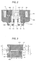
- Fig.2 is a partially enlarged vertical cross sectional view showing around the annular end face portion of opposed stationary core and movable core in the vertical cross sectional view of Fig.1 .
- a fuel injection valve main body 100 comprises a hollow stationary core 107 having a fuel passage 112 therein, a yoke 109 serving also as a housing, a nozzle body 104, a movable core 106 and a valve element 101.
- the needle shaped-valve element 101 is inserted through a middle aperture of the movable core 106 in a cylindrical shape with a bottom so as to enable to move relative to the movable core in an axial direction thereof.
- a flange 101A is provided integrally with the valve element, and the flange 101A is supported on the inside of the bottom of the movable core 106.
- the inside of the stationary core 107 is provided with a spring 110 that applies the spring load to the valve element 101 in a valve-closing-direction, namely, toward a seat portion 102A provided at the lower end side of the nozzle body 104 and an adjustor 113 for adjusting the spring load of the spring.
- the spring 110 is disposed between the adjustor 113 and the upper surface of the flange 101A of the valve element 101 to apply the spring load to the valve element 101 in the valve-closing direction.
- a buffer spring 114 is disposed between the outside of the bottom of the movable core 106 and a valve element guide member 105 fixed at the upper side of the nozzle body 104.
- the force of the buffer spring 114 is set to be sufficiently smaller than the spring 110.
- valve element 101 When the movable core 106 is magnetically attracted to the the stationary core 107 side by energizing the electromagnetic coil 108, the valve element 101 is lifted up together with the movable core 106 to do valve-opening operation. In contrast to that, when the energization to the electromagnetic coil 108 is turned off, the valve element 101 is press-returned in the valve-closing direction (toward the seat 102A) by the force of the spring 110, and the movable core 106 also receives the press-returned force via the flange portion 101A of the valve element 101 and moves together with the valve element 101.
- the stationary core 107, the yoke 109 and the movable core 106 serve as constitutional elements for a magnetic circuit.
- the yoke 109, the nozzle body 104 and the stationary core 107 are joined by welding.
- the electromagnetic coil 108 sealed by resin mold is incorporated within the yoke 109.
- an orifice plate 102 provided with the seat 102A and an orifice (illustration is omitted) serving as an injection hole is fixed by welding.
- the movable core 106, the valve element 101, an upper side valve guide member 105 and a lower side valve guide member 103 are incorporated inside the nozzle body 104.
- the fuel passage in the injection valve is constituted by the inner flow passage 112 in the stationary core 107, a plurality of holes 106A provided in the movable core 106, a plurality of holes 105A provided in the guide member 105, the inside of the nozzle body 104 and a plurality of holes 103A provided in the guide member 103.
- a resin cover 111 is provided with a connector portion 111A for supplying an excitation current (pulse current) to the electromagnetic coil 108, and a part of a lead terminal 115 insulated by the resin cover 111 positions in the connector portion 111A.
- the stationary core 107, the yoke 109 and the movable core 106 constitute a magnetic circuit
- the movable core 106 is magnetically attracted against the force of the spring 110, and collides with the downstream side end face of the stationary core 107.
- the valve element 101 is also lifted up by the movable core 106 and removes from the seat 102A to make an open valve condition, and the fuel in the injection valve main body that is pressurized in advance (more than 10MPa) by an external high pressure pump (not illustrated) is injected via the injection hole.
- valve element 101 When excitation of the electromagnetic coil 108 is turned off, the valve element 101 is pressed to the seat portion 102A side by the force of the spring 110 to thereby make a close valve condition.
- the movable core 106 moves slightly relative to the valve element 101 due to inertia force against the buffer spring 114, thereafter the movable core 106 is returned to a position where the same comes into contact with the flange portion 101A of the valve element 101 by the force of the buffer spring 114.
- Fig.3 is a partially enlarged vertical cross sectional view (around the portion indicated by symbol P in Figs.1 and 2 ) of an prime portion showing the annular end face portions of the stationary core and movable core of the fuel injection valve according to a first embodiment of the present invention.
- annular protuberance 106C constituting the collision portion against the stationary core 107 is provided on the annular end face 106A at the movable core 106 side.
- the annular protuberance (collision portion) 106C is provided at an inner side from the middle position in the width direction of the annular end face 106A.
- Fig.3 shows a condition where the movable core 106 is magnetically attracted to the side of the stationary core 107.
- Areas of non-collision portions for keeping fluid gap Gf are constituted by the areas of the outer side and the inner side from the annular protuberance 106C representing the collision portion.
- the annular end faces 107A and 106A of the stationary core 107 and the movable core 106 are applied with platings 30 and 31 having anti wear property.
- the plated coatings are of non magnetic materials, for example, constituted by such as hard chromium coating or electroless nickel coating.
- the thickness of the plating 30 at the stationary core 107 side is formed uniformly
- the thickness of the plating 31 at the movable core 106 side is formed in such a manner that the coating thickness t1 at the collision portion (protuberance portion) 106C is maximized, the coating thickness t1' at the area of non-collision portion outside the collision portion is formed thinner than t1 and the thickness thereof is continuously (in sloping manner) decreased toward the side of outer diameter Do of the movable core 106.
- the magnetic gap Gm at the time of valve-closing is determined by adding to the above total sum the separated distance between the collision portions of the movable core and the stationary core. Further, the fluid gap Gf is a value obtained by subtracting the plating thickness from the magnetic gap Gm.
- the most part of the non-collision portion is located outside (outer diameter side) from the collision portion and the area is larger than other area thereof because the part is located at the outer side. For this reason, a force due to squeeze effect acting on the area of the non-collision portion becomes large, and which causes to reduce the responsivity. Since the plating thickness t1' at the non-collision portion is made thinner than the plating thickness t1 at the collision portion (t1' is made to decrease continuously), the fluid gap Gf between the movable core and the stationary core at the non-collision portion located outside from the collision portion satisfies a relationship of fluid gap (Gf)>height h of collision portion (protuberance portion) 106C.
- the outer diameter of the movable core 106 is about 10 mm
- the inner diameter thereof is about 5 mm
- the width W of the annular end face is about 2.5 mm
- the height h of the collision portion as in the range of 10 ⁇ 25 ⁇ m (herein 20 ⁇ m)
- the plating thickness t1 at the collision portion as in the range of 10 ⁇ 20 ⁇ m (herein 15 ⁇ m)
- the plating thickness t2 at the stationary core 107 as about 10 ⁇ m
- the plating thickness t1' at the outer diameter position of the movable core as below 5 ⁇ m
- the plating thickness t1' is of the non-collision portion outside from the collision portion and is continuously decreased from the thickness at the collision portion toward the outer diameter of the movable core
- it is preferable to determine the magnetic gap Gm as about 45 ⁇ m and the fluid gap Gf as about 25 ⁇ m ⁇ 30 ⁇ m.
- the fluid gap can be increased by about 5 ⁇ 15 ⁇ m in comparison with those not using the present invention. Since the fluid resistance force due to squeeze effect is proportional to a cube of size of the fluid gap, even when the fluid gap increase is of about 5 ⁇ m, an advantage of reducing the force due to squeeze effect can be obtained.
- the operation responsivity of the movable core from turning off energization to the electromagnetic coil until the valve-closing can be improved and the delay of valve-closing can be improved by 20% ⁇ 50% in comparison with the comparative example.
- This improved advantage can contribute to higher dynamic range and higher fuel pressure that are particularly required for recent engines.
- the present embodiment it is possible to satisfy the conditions for reducing the magnetic gap (enhancement of magnetic attraction force) by decreasing the height of the collision portion (protuberance portion) and for decreasing the fluid gap (reduction of fluid resistance force: squeeze effect) while keeping a sufficient thickness of the plating at the collision portion in view of durability thereof.
- a method of varying the plating thickness in the case of electrolytic plating such as hard chromium, can be executed by an arrangement of plating electrodes being set in such a manner that the plating current density is set higher at a portion where the plating thickness is desired to be thicker than at other portions and the plating current density is set lower at a portion where the plating thickness is desired to be thin than at other portions.
- the plating current density and plating current flowing time can be set arbitrary depending on the plating thickness.
- the annular protuberance 106C and the structure of the plating 31 of which thickness varies as above can be provided at the stationary core 107 side instead of the movable core 106 side.
- the annular protuberance 106C can be provided at the outer side from the middle position in the width direction of the annular end face, and the plating 31 can be formed from the collision portion (annular protuberance 106C) toward the inner side in the width direction of the annular end face in such a manner that the thickness thereof continuously decreases.
- Figs. 4 and 7 ⁇ 9 are vertical cross sectional views showing prime parts of other embodiments of the present invention, and the same reference numerals as in the previous embodiment show the same or equivalent elements as those therein. Further, in Figs. 4 and 7 ⁇ 9 , the fuel injection valve is shown in valve closed condition, namely, the condition where the movable core 106 is separated from the stationary core 107.
- Fig.4 is a second embodiment of the present invention, in which the thickness of a plating 30 on a downstream side-annular end face 107A of the stationary core 107 is also continuously decreased with a gradient from the inner side toward the outer side like the side of the movable core 106.
- the constitution other than the thickness of the plating 30 is the same as of the first embodiment.
- Fig.7 is an enlarged vertical cross sectional view showing prime portions of a third embodiment of the present invention.
- a collision portion 106F provided on the movable core 106 is formed by an annular portion 106F provided at the inner side from the middle position in the width direction of the annular end face 106A. Further, this annular portion 106F is formed with a plane annular width between an outside tapered portion 106D and an inside tapered portion 106E, which will be explained later.
- the tapered portion 106D is formed so as to incline in the direction opposite to the stationary core 107 from this annular portion 106F toward the outer diameter of the movable core 106.
- the non-collision portion between the cores is formed by this tapered portion.
- the plating 31 is formed so that the thickness thereof continuously decreases from the collision portion (annular portion) 106F toward the outer diameter side the movable core. The thickness of the plating 31 on the collision portion 106F and on the inner side therefrom is made thicker than that on the outer side.
- Fig.8 is an enlarged vertical cross sectional view showing prime portions of a fourth embodiment of the present invention.
- the collision portion and the structure of the tapered portion are inverted as those in the third embodiment.
- the collision portion provided on the movable core 106 is formed by an annular portion 106F' provided at the inner side from the middle position in the width direction of the annular end face 106A. Further, this annular portion 106F' is formed with a plane annular width between an outside tapered portion 106D' and an inside tapered portion 106E', which will be explained later.
- the tapered portion 106E' is formed so as to incline in the direction opposite to the stationary core 107 from this annular portion 106F' toward the inner diameter of the movable core 106.
- the plating 31 is formed so that the thickness thereof continuously decreases from the collision portion (annular portion) 106F' toward the outer side of the movable core.
- annular collision portions (106F, 106F') at the side of the movable core and the tapered portions (106D, 10 6D' , 106E, 106E') as shown in connection with the third and fourth embodiments can be provided at the side of the stationary core instead of at the side of the movable core.
- Fig.9 is an enlarged vertical cross sectional view showing important portions of a fifth embodiment of the present invention.
- the collision portion (annular protuberance) 106C provided on the annular end face 106A of the movable core 106 is provided at the inner side from the middle position in the width direction of the annular end face.
- the annular end face 106A of the movable core 106 is divided in radial direction into two parts as an inner side and an outer side, the inner side is provided with an area 31 for forming a plating of anti wear property and the outer side is provided with an area 41 of non-plating.
- the annular protuberance 106C serving as the collision portion is coated by the plating 31, and the non-collision portion is constituted by the non-plating area 41.
- annular end face 107A of the stationary core 107 is also divided in radial direction into two parts as an inner side and an outer side, and the inner side is used as an area 30 for forming a plating and the outer side is used as an area of non-plating.
- the collision portion (annular protuberance) 106C can be provided at the outer side from the middle position in the width direction of the annular end face.
- the annular end face 106A of the movable core 106 is divided in radial direction into two parts as an inner side and an outer side.
- the outer side is provided with an area 31 for forming a plating of anti wear property and the inner side is provided with an area 41 of non-plating.
- the annular protuberance 106C serving as the collision portion is coated by the plating 31, and the non-collision portion is constituted by the non-plating area 41.
- the annular end face 107A of the stationary core 107 is also divided in radial direction into two parts as an inner side and an outer side, the outer side is provided with an area 30 for forming a plating and the inner side is provided with an area of non-plating.
Landscapes
- Engineering & Computer Science (AREA)
- Physics & Mathematics (AREA)
- Electromagnetism (AREA)
- Chemical & Material Sciences (AREA)
- Combustion & Propulsion (AREA)
- Mechanical Engineering (AREA)
- General Engineering & Computer Science (AREA)
- Fuel-Injection Apparatus (AREA)
Applications Claiming Priority (2)
| Application Number | Priority Date | Filing Date | Title |
|---|---|---|---|
| JP2008237501A JP5048617B2 (ja) | 2008-09-17 | 2008-09-17 | 内燃機関用の燃料噴射弁 |
| PCT/JP2009/003571 WO2010032357A1 (fr) | 2008-09-17 | 2009-07-29 | Soupape d'injection de carburant pour moteur à combustion interne |
Publications (3)
| Publication Number | Publication Date |
|---|---|
| EP2325473A1 true EP2325473A1 (fr) | 2011-05-25 |
| EP2325473A4 EP2325473A4 (fr) | 2011-11-09 |
| EP2325473B1 EP2325473B1 (fr) | 2015-09-09 |
Family
ID=42039210
Family Applications (1)
| Application Number | Title | Priority Date | Filing Date |
|---|---|---|---|
| EP09814203.7A Active EP2325473B1 (fr) | 2008-09-17 | 2009-07-29 | Soupape d'injection de carburant pour moteur à combustion interne |
Country Status (4)
| Country | Link |
|---|---|
| US (1) | US8991783B2 (fr) |
| EP (1) | EP2325473B1 (fr) |
| JP (1) | JP5048617B2 (fr) |
| WO (1) | WO2010032357A1 (fr) |
Cited By (7)
| Publication number | Priority date | Publication date | Assignee | Title |
|---|---|---|---|---|
| EP2644879A1 (fr) * | 2012-03-26 | 2013-10-02 | Robert Bosch Gmbh | Procédé de fabrication d'une électrovanne |
| WO2014048609A1 (fr) * | 2012-09-25 | 2014-04-03 | Robert Bosch Gmbh | Soupape d'injection |
| WO2015106878A1 (fr) * | 2014-01-15 | 2015-07-23 | Delphi International Operations Luxembourg S.À R.L. | Actionneur comprenant une armature magnétique dotée d'un élément intercalaire intégré |
| DE102014220100B3 (de) * | 2014-10-02 | 2016-01-28 | Continental Automotive Gmbh | Kraftstoffeinspritzventil und Verfahren zum Herstellen eines solchen |
| WO2017021286A1 (fr) * | 2015-08-05 | 2017-02-09 | Delphi International Operations Luxembourg S.À R.L. | Agencement d'actionneur |
| EP3118442A4 (fr) * | 2014-03-14 | 2017-12-27 | Hitachi Automotive Systems, Ltd. | Électrovanne |
| WO2019115057A1 (fr) * | 2017-12-15 | 2019-06-20 | Robert Bosch Gmbh | Soupape d'admission à actionnement électromagnétique et pompe à carburant haute pression |
Families Citing this family (9)
| Publication number | Priority date | Publication date | Assignee | Title |
|---|---|---|---|---|
| JP2012246789A (ja) * | 2011-05-25 | 2012-12-13 | Denso Corp | 燃料噴射弁 |
| JP5982210B2 (ja) * | 2012-07-27 | 2016-08-31 | 日立オートモティブシステムズ株式会社 | 電磁式燃料噴射弁 |
| JP6605371B2 (ja) * | 2016-03-14 | 2019-11-13 | 日立オートモティブシステムズ株式会社 | 電磁ソレノイド及び燃料噴射弁 |
| CN109891081B (zh) * | 2016-11-07 | 2021-01-19 | 三菱电机株式会社 | 燃料喷射阀 |
| DE102016222912A1 (de) * | 2016-11-21 | 2018-05-24 | Robert Bosch Gmbh | Injektorbauteil mit Beschichtung, Injektor sowie Vorrichtung zum Beschichten |
| JP2018159294A (ja) * | 2017-03-22 | 2018-10-11 | 株式会社ケーヒン | 燃料噴射弁 |
| JP7338155B2 (ja) * | 2019-01-08 | 2023-09-05 | 株式会社デンソー | 燃料噴射弁 |
| JP6788085B1 (ja) * | 2019-09-20 | 2020-11-18 | 株式会社ケーヒン | 電磁式燃料噴射弁 |
| JP7482073B2 (ja) | 2021-03-22 | 2024-05-13 | 日立Astemo株式会社 | 電磁式燃料噴射弁 |
Citations (2)
| Publication number | Priority date | Publication date | Assignee | Title |
|---|---|---|---|---|
| DE4421947A1 (de) * | 1993-12-09 | 1995-06-14 | Bosch Gmbh Robert | Elektromagnetisch betätigbares Ventil |
| US20060214033A1 (en) * | 2005-03-25 | 2006-09-28 | Aisan Kogyo Kabushiki Kaisha | Fuel injector |
Family Cites Families (9)
| Publication number | Priority date | Publication date | Assignee | Title |
|---|---|---|---|---|
| WO1995016126A1 (fr) * | 1993-12-09 | 1995-06-15 | Robert Bosch Gmbh | Soupape a commande electromagnetique |
| DE19654322C2 (de) * | 1996-12-24 | 1999-12-23 | Bosch Gmbh Robert | Elektromagnetisch betätigbares Ventil |
| DE10039083A1 (de) * | 2000-08-10 | 2002-02-21 | Bosch Gmbh Robert | Brennstoffeinspritzventil |
| JP3931329B2 (ja) | 2002-05-15 | 2007-06-13 | 株式会社デンソー | 燃料噴射装置 |
| WO2004055357A1 (fr) * | 2002-12-13 | 2004-07-01 | Robert Bosch Gmbh | Actionneur magnetique exempt d'impulsions rebondissantes pour des soupapes d'injection |
| JP2005036696A (ja) * | 2003-07-18 | 2005-02-10 | Hitachi Ltd | 電磁駆動式燃料噴射弁 |
| JP2006022727A (ja) | 2004-07-08 | 2006-01-26 | Aisan Ind Co Ltd | 燃料噴射弁 |
| JP4168448B2 (ja) * | 2004-07-08 | 2008-10-22 | 株式会社デンソー | 燃料噴射弁 |
| EP2077389B1 (fr) * | 2006-09-25 | 2013-01-30 | Hitachi Ltd. | Soupape d'injection de carburant |
-
2008
- 2008-09-17 JP JP2008237501A patent/JP5048617B2/ja active Active
-
2009
- 2009-07-29 US US12/920,559 patent/US8991783B2/en active Active
- 2009-07-29 WO PCT/JP2009/003571 patent/WO2010032357A1/fr active Application Filing
- 2009-07-29 EP EP09814203.7A patent/EP2325473B1/fr active Active
Patent Citations (2)
| Publication number | Priority date | Publication date | Assignee | Title |
|---|---|---|---|---|
| DE4421947A1 (de) * | 1993-12-09 | 1995-06-14 | Bosch Gmbh Robert | Elektromagnetisch betätigbares Ventil |
| US20060214033A1 (en) * | 2005-03-25 | 2006-09-28 | Aisan Kogyo Kabushiki Kaisha | Fuel injector |
Non-Patent Citations (1)
| Title |
|---|
| See also references of WO2010032357A1 * |
Cited By (13)
| Publication number | Priority date | Publication date | Assignee | Title |
|---|---|---|---|---|
| US9429245B2 (en) | 2012-03-26 | 2016-08-30 | Robert Bosch Gmbh | Method for manufacturing a solenoid valve |
| US9885101B2 (en) | 2012-03-26 | 2018-02-06 | Robert Bosch Gmbh | Method for manufacturing a solenoid valve |
| EP2644879A1 (fr) * | 2012-03-26 | 2013-10-02 | Robert Bosch Gmbh | Procédé de fabrication d'une électrovanne |
| US9546630B2 (en) | 2012-09-25 | 2017-01-17 | Robert Bosch Gmbh | Injection valve |
| KR20150056789A (ko) * | 2012-09-25 | 2015-05-27 | 로베르트 보쉬 게엠베하 | 분사 밸브 |
| WO2014048609A1 (fr) * | 2012-09-25 | 2014-04-03 | Robert Bosch Gmbh | Soupape d'injection |
| KR102110114B1 (ko) | 2012-09-25 | 2020-05-14 | 로베르트 보쉬 게엠베하 | 분사 밸브 |
| WO2015106878A1 (fr) * | 2014-01-15 | 2015-07-23 | Delphi International Operations Luxembourg S.À R.L. | Actionneur comprenant une armature magnétique dotée d'un élément intercalaire intégré |
| EP3118442A4 (fr) * | 2014-03-14 | 2017-12-27 | Hitachi Automotive Systems, Ltd. | Électrovanne |
| US10190555B2 (en) | 2014-03-14 | 2019-01-29 | Hitachi Automotive Systems, Ltd. | Electromagnetic valve |
| DE102014220100B3 (de) * | 2014-10-02 | 2016-01-28 | Continental Automotive Gmbh | Kraftstoffeinspritzventil und Verfahren zum Herstellen eines solchen |
| WO2017021286A1 (fr) * | 2015-08-05 | 2017-02-09 | Delphi International Operations Luxembourg S.À R.L. | Agencement d'actionneur |
| WO2019115057A1 (fr) * | 2017-12-15 | 2019-06-20 | Robert Bosch Gmbh | Soupape d'admission à actionnement électromagnétique et pompe à carburant haute pression |
Also Published As
| Publication number | Publication date |
|---|---|
| JP2010071123A (ja) | 2010-04-02 |
| US20110155103A1 (en) | 2011-06-30 |
| JP5048617B2 (ja) | 2012-10-17 |
| US8991783B2 (en) | 2015-03-31 |
| EP2325473B1 (fr) | 2015-09-09 |
| WO2010032357A1 (fr) | 2010-03-25 |
| EP2325473A4 (fr) | 2011-11-09 |
Similar Documents
| Publication | Publication Date | Title |
|---|---|---|
| EP2325473B1 (fr) | Soupape d'injection de carburant pour moteur à combustion interne | |
| EP2136068B1 (fr) | Injecteur de carburant électromagnétique et son procédé d'assemblage | |
| US5769391A (en) | Electromagnetically actuated valve | |
| US6695233B2 (en) | Electromagnetic fuel injection valve | |
| EP1998039B1 (fr) | Injecteur de carburant et son procédé de réglage de course | |
| US11703021B2 (en) | Fuel injection device | |
| US9291135B2 (en) | Electromagnetic fuel injection valve | |
| EP2570648B1 (fr) | Valve électromagnétique d'injection de carburant | |
| JP5239965B2 (ja) | 燃料噴射弁 | |
| EP1878908A2 (fr) | Injecteur de carburant électromagnétique | |
| JP2000505863A (ja) | 電磁作動式の弁 | |
| JP5262972B2 (ja) | 燃料噴射弁 | |
| JP5152024B2 (ja) | 燃料噴射弁 | |
| US6783109B2 (en) | Electromagnetic fuel injection valve | |
| JP4577654B2 (ja) | 電磁駆動装置およびこれを用いた燃料噴射弁 | |
| US20020125343A1 (en) | Fuel injector valve | |
| JP2005036696A (ja) | 電磁駆動式燃料噴射弁 | |
| JP4285701B2 (ja) | 燃料噴射弁 | |
| CN111356835B (zh) | 燃料喷射阀 | |
| US20030038263A1 (en) | Electromagnetic actuator for a fuel injector |
Legal Events
| Date | Code | Title | Description |
|---|---|---|---|
| PUAI | Public reference made under article 153(3) epc to a published international application that has entered the european phase |
Free format text: ORIGINAL CODE: 0009012 |
|
| 17P | Request for examination filed |
Effective date: 20110418 |
|
| AK | Designated contracting states |
Kind code of ref document: A1 Designated state(s): AT BE BG CH CY CZ DE DK EE ES FI FR GB GR HR HU IE IS IT LI LT LU LV MC MK MT NL NO PL PT RO SE SI SK SM TR |
|
| AX | Request for extension of the european patent |
Extension state: AL BA RS |
|
| A4 | Supplementary search report drawn up and despatched |
Effective date: 20111010 |
|
| RIC1 | Information provided on ipc code assigned before grant |
Ipc: F02M 51/06 20060101AFI20111004BHEP |
|
| DAX | Request for extension of the european patent (deleted) | ||
| 17Q | First examination report despatched |
Effective date: 20121121 |
|
| GRAP | Despatch of communication of intention to grant a patent |
Free format text: ORIGINAL CODE: EPIDOSNIGR1 |
|
| INTG | Intention to grant announced |
Effective date: 20150324 |
|
| GRAS | Grant fee paid |
Free format text: ORIGINAL CODE: EPIDOSNIGR3 |
|
| GRAA | (expected) grant |
Free format text: ORIGINAL CODE: 0009210 |
|
| RIN1 | Information on inventor provided before grant (corrected) |
Inventor name: TAKAOKU, ATSUSHI Inventor name: NAMAIZAWA, YASUO Inventor name: KOWATARI, TAKEHIKO Inventor name: IRINO, YUSUKE Inventor name: ISHIKAWA, TOHRU Inventor name: HAYATANI, MASAHIKO Inventor name: ABE, MOTOYUKI |
|
| AK | Designated contracting states |
Kind code of ref document: B1 Designated state(s): AT BE BG CH CY CZ DE DK EE ES FI FR GB GR HR HU IE IS IT LI LT LU LV MC MK MT NL NO PL PT RO SE SI SK SM TR |
|
| REG | Reference to a national code |
Ref country code: GB Ref legal event code: FG4D |
|
| REG | Reference to a national code |
Ref country code: AT Ref legal event code: REF Ref document number: 748340 Country of ref document: AT Kind code of ref document: T Effective date: 20150915 Ref country code: CH Ref legal event code: EP |
|
| REG | Reference to a national code |
Ref country code: IE Ref legal event code: FG4D |
|
| REG | Reference to a national code |
Ref country code: DE Ref legal event code: R096 Ref document number: 602009033579 Country of ref document: DE |
|
| REG | Reference to a national code |
Ref country code: NL Ref legal event code: MP Effective date: 20150909 |
|
| PG25 | Lapsed in a contracting state [announced via postgrant information from national office to epo] |
Ref country code: LT Free format text: LAPSE BECAUSE OF FAILURE TO SUBMIT A TRANSLATION OF THE DESCRIPTION OR TO PAY THE FEE WITHIN THE PRESCRIBED TIME-LIMIT Effective date: 20150909 Ref country code: FI Free format text: LAPSE BECAUSE OF FAILURE TO SUBMIT A TRANSLATION OF THE DESCRIPTION OR TO PAY THE FEE WITHIN THE PRESCRIBED TIME-LIMIT Effective date: 20150909 Ref country code: NO Free format text: LAPSE BECAUSE OF FAILURE TO SUBMIT A TRANSLATION OF THE DESCRIPTION OR TO PAY THE FEE WITHIN THE PRESCRIBED TIME-LIMIT Effective date: 20151209 Ref country code: GR Free format text: LAPSE BECAUSE OF FAILURE TO SUBMIT A TRANSLATION OF THE DESCRIPTION OR TO PAY THE FEE WITHIN THE PRESCRIBED TIME-LIMIT Effective date: 20151210 Ref country code: LV Free format text: LAPSE BECAUSE OF FAILURE TO SUBMIT A TRANSLATION OF THE DESCRIPTION OR TO PAY THE FEE WITHIN THE PRESCRIBED TIME-LIMIT Effective date: 20150909 |
|
| REG | Reference to a national code |
Ref country code: LT Ref legal event code: MG4D |
|
| REG | Reference to a national code |
Ref country code: AT Ref legal event code: MK05 Ref document number: 748340 Country of ref document: AT Kind code of ref document: T Effective date: 20150909 |
|
| PG25 | Lapsed in a contracting state [announced via postgrant information from national office to epo] |
Ref country code: SE Free format text: LAPSE BECAUSE OF FAILURE TO SUBMIT A TRANSLATION OF THE DESCRIPTION OR TO PAY THE FEE WITHIN THE PRESCRIBED TIME-LIMIT Effective date: 20150909 Ref country code: ES Free format text: LAPSE BECAUSE OF FAILURE TO SUBMIT A TRANSLATION OF THE DESCRIPTION OR TO PAY THE FEE WITHIN THE PRESCRIBED TIME-LIMIT Effective date: 20150909 Ref country code: HR Free format text: LAPSE BECAUSE OF FAILURE TO SUBMIT A TRANSLATION OF THE DESCRIPTION OR TO PAY THE FEE WITHIN THE PRESCRIBED TIME-LIMIT Effective date: 20150909 |
|
| PG25 | Lapsed in a contracting state [announced via postgrant information from national office to epo] |
Ref country code: NL Free format text: LAPSE BECAUSE OF FAILURE TO SUBMIT A TRANSLATION OF THE DESCRIPTION OR TO PAY THE FEE WITHIN THE PRESCRIBED TIME-LIMIT Effective date: 20150909 |
|
| PG25 | Lapsed in a contracting state [announced via postgrant information from national office to epo] |
Ref country code: EE Free format text: LAPSE BECAUSE OF FAILURE TO SUBMIT A TRANSLATION OF THE DESCRIPTION OR TO PAY THE FEE WITHIN THE PRESCRIBED TIME-LIMIT Effective date: 20150909 Ref country code: SK Free format text: LAPSE BECAUSE OF FAILURE TO SUBMIT A TRANSLATION OF THE DESCRIPTION OR TO PAY THE FEE WITHIN THE PRESCRIBED TIME-LIMIT Effective date: 20150909 Ref country code: IS Free format text: LAPSE BECAUSE OF FAILURE TO SUBMIT A TRANSLATION OF THE DESCRIPTION OR TO PAY THE FEE WITHIN THE PRESCRIBED TIME-LIMIT Effective date: 20160109 Ref country code: CZ Free format text: LAPSE BECAUSE OF FAILURE TO SUBMIT A TRANSLATION OF THE DESCRIPTION OR TO PAY THE FEE WITHIN THE PRESCRIBED TIME-LIMIT Effective date: 20150909 Ref country code: IT Free format text: LAPSE BECAUSE OF FAILURE TO SUBMIT A TRANSLATION OF THE DESCRIPTION OR TO PAY THE FEE WITHIN THE PRESCRIBED TIME-LIMIT Effective date: 20150909 |
|
| PG25 | Lapsed in a contracting state [announced via postgrant information from national office to epo] |
Ref country code: PL Free format text: LAPSE BECAUSE OF FAILURE TO SUBMIT A TRANSLATION OF THE DESCRIPTION OR TO PAY THE FEE WITHIN THE PRESCRIBED TIME-LIMIT Effective date: 20150909 Ref country code: AT Free format text: LAPSE BECAUSE OF FAILURE TO SUBMIT A TRANSLATION OF THE DESCRIPTION OR TO PAY THE FEE WITHIN THE PRESCRIBED TIME-LIMIT Effective date: 20150909 Ref country code: RO Free format text: LAPSE BECAUSE OF FAILURE TO SUBMIT A TRANSLATION OF THE DESCRIPTION OR TO PAY THE FEE WITHIN THE PRESCRIBED TIME-LIMIT Effective date: 20150909 Ref country code: PT Free format text: LAPSE BECAUSE OF FAILURE TO SUBMIT A TRANSLATION OF THE DESCRIPTION OR TO PAY THE FEE WITHIN THE PRESCRIBED TIME-LIMIT Effective date: 20160111 |
|
| REG | Reference to a national code |
Ref country code: DE Ref legal event code: R097 Ref document number: 602009033579 Country of ref document: DE |
|
| PLBE | No opposition filed within time limit |
Free format text: ORIGINAL CODE: 0009261 |
|
| STAA | Information on the status of an ep patent application or granted ep patent |
Free format text: STATUS: NO OPPOSITION FILED WITHIN TIME LIMIT |
|
| 26N | No opposition filed |
Effective date: 20160610 |
|
| PG25 | Lapsed in a contracting state [announced via postgrant information from national office to epo] |
Ref country code: SI Free format text: LAPSE BECAUSE OF FAILURE TO SUBMIT A TRANSLATION OF THE DESCRIPTION OR TO PAY THE FEE WITHIN THE PRESCRIBED TIME-LIMIT Effective date: 20150909 Ref country code: DK Free format text: LAPSE BECAUSE OF FAILURE TO SUBMIT A TRANSLATION OF THE DESCRIPTION OR TO PAY THE FEE WITHIN THE PRESCRIBED TIME-LIMIT Effective date: 20150909 |
|
| PG25 | Lapsed in a contracting state [announced via postgrant information from national office to epo] |
Ref country code: BE Free format text: LAPSE BECAUSE OF FAILURE TO SUBMIT A TRANSLATION OF THE DESCRIPTION OR TO PAY THE FEE WITHIN THE PRESCRIBED TIME-LIMIT Effective date: 20150909 |
|
| REG | Reference to a national code |
Ref country code: CH Ref legal event code: PL |
|
| GBPC | Gb: european patent ceased through non-payment of renewal fee |
Effective date: 20160729 |
|
| PG25 | Lapsed in a contracting state [announced via postgrant information from national office to epo] |
Ref country code: MC Free format text: LAPSE BECAUSE OF FAILURE TO SUBMIT A TRANSLATION OF THE DESCRIPTION OR TO PAY THE FEE WITHIN THE PRESCRIBED TIME-LIMIT Effective date: 20150909 |
|
| PG25 | Lapsed in a contracting state [announced via postgrant information from national office to epo] |
Ref country code: LI Free format text: LAPSE BECAUSE OF NON-PAYMENT OF DUE FEES Effective date: 20160731 Ref country code: FR Free format text: LAPSE BECAUSE OF NON-PAYMENT OF DUE FEES Effective date: 20160801 Ref country code: CH Free format text: LAPSE BECAUSE OF NON-PAYMENT OF DUE FEES Effective date: 20160731 |
|
| REG | Reference to a national code |
Ref country code: FR Ref legal event code: ST Effective date: 20170331 |
|
| REG | Reference to a national code |
Ref country code: IE Ref legal event code: MM4A |
|
| PG25 | Lapsed in a contracting state [announced via postgrant information from national office to epo] |
Ref country code: GB Free format text: LAPSE BECAUSE OF NON-PAYMENT OF DUE FEES Effective date: 20160729 |
|
| PG25 | Lapsed in a contracting state [announced via postgrant information from national office to epo] |
Ref country code: IE Free format text: LAPSE BECAUSE OF NON-PAYMENT OF DUE FEES Effective date: 20160729 |
|
| PG25 | Lapsed in a contracting state [announced via postgrant information from national office to epo] |
Ref country code: LU Free format text: LAPSE BECAUSE OF NON-PAYMENT OF DUE FEES Effective date: 20160729 |
|
| PG25 | Lapsed in a contracting state [announced via postgrant information from national office to epo] |
Ref country code: CY Free format text: LAPSE BECAUSE OF FAILURE TO SUBMIT A TRANSLATION OF THE DESCRIPTION OR TO PAY THE FEE WITHIN THE PRESCRIBED TIME-LIMIT Effective date: 20150909 Ref country code: SM Free format text: LAPSE BECAUSE OF FAILURE TO SUBMIT A TRANSLATION OF THE DESCRIPTION OR TO PAY THE FEE WITHIN THE PRESCRIBED TIME-LIMIT Effective date: 20150909 Ref country code: HU Free format text: LAPSE BECAUSE OF FAILURE TO SUBMIT A TRANSLATION OF THE DESCRIPTION OR TO PAY THE FEE WITHIN THE PRESCRIBED TIME-LIMIT; INVALID AB INITIO Effective date: 20090729 |
|
| PG25 | Lapsed in a contracting state [announced via postgrant information from national office to epo] |
Ref country code: TR Free format text: LAPSE BECAUSE OF FAILURE TO SUBMIT A TRANSLATION OF THE DESCRIPTION OR TO PAY THE FEE WITHIN THE PRESCRIBED TIME-LIMIT Effective date: 20150909 Ref country code: MT Free format text: LAPSE BECAUSE OF NON-PAYMENT OF DUE FEES Effective date: 20160731 Ref country code: MK Free format text: LAPSE BECAUSE OF FAILURE TO SUBMIT A TRANSLATION OF THE DESCRIPTION OR TO PAY THE FEE WITHIN THE PRESCRIBED TIME-LIMIT Effective date: 20150909 |
|
| PG25 | Lapsed in a contracting state [announced via postgrant information from national office to epo] |
Ref country code: BG Free format text: LAPSE BECAUSE OF FAILURE TO SUBMIT A TRANSLATION OF THE DESCRIPTION OR TO PAY THE FEE WITHIN THE PRESCRIBED TIME-LIMIT Effective date: 20150909 |
|
| REG | Reference to a national code |
Ref country code: DE Ref legal event code: R082 Ref document number: 602009033579 Country of ref document: DE Representative=s name: MERH-IP MATIAS ERNY REICHL HOFFMANN PATENTANWA, DE Ref country code: DE Ref legal event code: R081 Ref document number: 602009033579 Country of ref document: DE Owner name: HITACHI ASTEMO, LTD., HITACHINAKA-SHI, JP Free format text: FORMER OWNER: HITACHI AUTOMOTIVE SYSTEMS, LTD., HITACHINAKA-SHI, IBARAKI, JP |
|
| PGFP | Annual fee paid to national office [announced via postgrant information from national office to epo] |
Ref country code: DE Payment date: 20230607 Year of fee payment: 15 |