EP2323973B1 - Verfahren zur herstellung von aromatischen isocyanaten - Google Patents
Verfahren zur herstellung von aromatischen isocyanaten Download PDFInfo
- Publication number
- EP2323973B1 EP2323973B1 EP09781542A EP09781542A EP2323973B1 EP 2323973 B1 EP2323973 B1 EP 2323973B1 EP 09781542 A EP09781542 A EP 09781542A EP 09781542 A EP09781542 A EP 09781542A EP 2323973 B1 EP2323973 B1 EP 2323973B1
- Authority
- EP
- European Patent Office
- Prior art keywords
- mixing chamber
- phosgene
- amine
- diameter
- axis
- Prior art date
- Legal status (The legal status is an assumption and is not a legal conclusion. Google has not performed a legal analysis and makes no representation as to the accuracy of the status listed.)
- Active
Links
- 239000012948 isocyanate Substances 0.000 title claims abstract description 19
- 238000004519 manufacturing process Methods 0.000 title claims abstract description 5
- -1 aromatic isocyanates Chemical class 0.000 title description 5
- 150000001412 amines Chemical class 0.000 claims abstract description 66
- YGYAWVDWMABLBF-UHFFFAOYSA-N Phosgene Chemical compound ClC(Cl)=O YGYAWVDWMABLBF-UHFFFAOYSA-N 0.000 claims abstract description 65
- 239000011541 reaction mixture Substances 0.000 claims abstract description 29
- 150000002513 isocyanates Chemical class 0.000 claims abstract description 14
- 238000011144 upstream manufacturing Methods 0.000 claims abstract description 14
- 239000007791 liquid phase Substances 0.000 claims abstract description 12
- 238000000034 method Methods 0.000 claims description 15
- UPMLOUAZCHDJJD-UHFFFAOYSA-N 4,4'-Diphenylmethane Diisocyanate Chemical compound C1=CC(N=C=O)=CC=C1CC1=CC=C(N=C=O)C=C1 UPMLOUAZCHDJJD-UHFFFAOYSA-N 0.000 description 6
- 125000005442 diisocyanate group Chemical group 0.000 description 4
- 239000012442 inert solvent Substances 0.000 description 4
- 239000000203 mixture Substances 0.000 description 4
- YXFVVABEGXRONW-UHFFFAOYSA-N Toluene Chemical compound CC1=CC=CC=C1 YXFVVABEGXRONW-UHFFFAOYSA-N 0.000 description 3
- MVPPADPHJFYWMZ-UHFFFAOYSA-N chlorobenzene Chemical compound ClC1=CC=CC=C1 MVPPADPHJFYWMZ-UHFFFAOYSA-N 0.000 description 3
- 238000002360 preparation method Methods 0.000 description 3
- 239000000376 reactant Substances 0.000 description 3
- 238000000926 separation method Methods 0.000 description 3
- NNOZGCICXAYKLW-UHFFFAOYSA-N 1,2-bis(2-isocyanatopropan-2-yl)benzene Chemical compound O=C=NC(C)(C)C1=CC=CC=C1C(C)(C)N=C=O NNOZGCICXAYKLW-UHFFFAOYSA-N 0.000 description 2
- PAYRUJLWNCNPSJ-UHFFFAOYSA-N Aniline Chemical compound NC1=CC=CC=C1 PAYRUJLWNCNPSJ-UHFFFAOYSA-N 0.000 description 2
- 229920000538 Poly[(phenyl isocyanate)-co-formaldehyde] Polymers 0.000 description 2
- 125000001931 aliphatic group Chemical group 0.000 description 2
- 150000004982 aromatic amines Chemical class 0.000 description 2
- 125000003118 aryl group Chemical group 0.000 description 2
- 230000015572 biosynthetic process Effects 0.000 description 2
- 230000007423 decrease Effects 0.000 description 2
- 150000004985 diamines Chemical class 0.000 description 2
- 238000009826 distribution Methods 0.000 description 2
- IQPQWNKOIGAROB-UHFFFAOYSA-N isocyanate group Chemical group [N-]=C=O IQPQWNKOIGAROB-UHFFFAOYSA-N 0.000 description 2
- NIMLQBUJDJZYEJ-UHFFFAOYSA-N isophorone diisocyanate Chemical compound CC1(C)CC(N=C=O)CC(C)(CN=C=O)C1 NIMLQBUJDJZYEJ-UHFFFAOYSA-N 0.000 description 2
- 239000012071 phase Substances 0.000 description 2
- RUELTTOHQODFPA-UHFFFAOYSA-N toluene 2,6-diisocyanate Chemical compound CC1=C(N=C=O)C=CC=C1N=C=O RUELTTOHQODFPA-UHFFFAOYSA-N 0.000 description 2
- ODKSRULWLOLNJQ-UHFFFAOYSA-N 1,2-diisocyanatocyclohexane Chemical compound O=C=NC1CCCCC1N=C=O ODKSRULWLOLNJQ-UHFFFAOYSA-N 0.000 description 1
- OHTRJOZKRSVAOX-UHFFFAOYSA-N 1,3-diisocyanato-2-methylcyclohexane Chemical compound CC1C(N=C=O)CCCC1N=C=O OHTRJOZKRSVAOX-UHFFFAOYSA-N 0.000 description 1
- ROHUXHMNZLHBSF-UHFFFAOYSA-N 1,4-bis(isocyanatomethyl)cyclohexane Chemical compound O=C=NCC1CCC(CN=C=O)CC1 ROHUXHMNZLHBSF-UHFFFAOYSA-N 0.000 description 1
- OCJBOOLMMGQPQU-UHFFFAOYSA-N 1,4-dichlorobenzene Chemical compound ClC1=CC=C(Cl)C=C1 OCJBOOLMMGQPQU-UHFFFAOYSA-N 0.000 description 1
- JMFCAIUTSABFDU-UHFFFAOYSA-N 1,6-diisocyanatohexane Chemical compound O=C=NCCCCCCN=C=O.O=C=NCCCCCCN=C=O JMFCAIUTSABFDU-UHFFFAOYSA-N 0.000 description 1
- ISXAKPTVAFBZTA-UHFFFAOYSA-N 1-(isocyanatomethyl)tricyclo[5.2.1.02,6]decane Chemical class N(=C=O)CC12C3CCCC3C(CC1)C2 ISXAKPTVAFBZTA-UHFFFAOYSA-N 0.000 description 1
- MKZPMOFOBNHBSL-UHFFFAOYSA-N 1-isocyanato-1-methylcyclohexane Chemical compound O=C=NC1(C)CCCCC1 MKZPMOFOBNHBSL-UHFFFAOYSA-N 0.000 description 1
- 239000005058 Isophorone diisocyanate Substances 0.000 description 1
- CVGYTOLNWAMTRJ-UHFFFAOYSA-N N=C=O.N=C=O.CCCCC(C)C(C)(C)C Chemical compound N=C=O.N=C=O.CCCCC(C)C(C)(C)C CVGYTOLNWAMTRJ-UHFFFAOYSA-N 0.000 description 1
- JTDWCIXOEPQECG-UHFFFAOYSA-N N=C=O.N=C=O.CCCCCC(C)(C)C Chemical compound N=C=O.N=C=O.CCCCCC(C)(C)C JTDWCIXOEPQECG-UHFFFAOYSA-N 0.000 description 1
- 208000031481 Pathologic Constriction Diseases 0.000 description 1
- XSQUKJJJFZCRTK-UHFFFAOYSA-N Urea Chemical compound NC(N)=O XSQUKJJJFZCRTK-UHFFFAOYSA-N 0.000 description 1
- 150000004945 aromatic hydrocarbons Chemical class 0.000 description 1
- 239000006227 byproduct Substances 0.000 description 1
- 239000004202 carbamide Substances 0.000 description 1
- 125000004432 carbon atom Chemical group C* 0.000 description 1
- 125000004122 cyclic group Chemical group 0.000 description 1
- 229940117389 dichlorobenzene Drugs 0.000 description 1
- 238000001704 evaporation Methods 0.000 description 1
- 230000008020 evaporation Effects 0.000 description 1
- ANSXAPJVJOKRDJ-UHFFFAOYSA-N furo[3,4-f][2]benzofuran-1,3,5,7-tetrone Chemical compound C1=C2C(=O)OC(=O)C2=CC2=C1C(=O)OC2=O ANSXAPJVJOKRDJ-UHFFFAOYSA-N 0.000 description 1
- 230000002452 interceptive effect Effects 0.000 description 1
- 239000000463 material Substances 0.000 description 1
- AYLRODJJLADBOB-QMMMGPOBSA-N methyl (2s)-2,6-diisocyanatohexanoate Chemical class COC(=O)[C@@H](N=C=O)CCCCN=C=O AYLRODJJLADBOB-QMMMGPOBSA-N 0.000 description 1
- DGTNSSLYPYDJGL-UHFFFAOYSA-N phenyl isocyanate Chemical compound O=C=NC1=CC=CC=C1 DGTNSSLYPYDJGL-UHFFFAOYSA-N 0.000 description 1
- 239000007787 solid Substances 0.000 description 1
- 239000007858 starting material Substances 0.000 description 1
- 208000037804 stenosis Diseases 0.000 description 1
- 230000036262 stenosis Effects 0.000 description 1
Images
Classifications
-
- C—CHEMISTRY; METALLURGY
- C07—ORGANIC CHEMISTRY
- C07C—ACYCLIC OR CARBOCYCLIC COMPOUNDS
- C07C263/00—Preparation of derivatives of isocyanic acid
- C07C263/10—Preparation of derivatives of isocyanic acid by reaction of amines with carbonyl halides, e.g. with phosgene
-
- B—PERFORMING OPERATIONS; TRANSPORTING
- B01—PHYSICAL OR CHEMICAL PROCESSES OR APPARATUS IN GENERAL
- B01F—MIXING, e.g. DISSOLVING, EMULSIFYING OR DISPERSING
- B01F23/00—Mixing according to the phases to be mixed, e.g. dispersing or emulsifying
- B01F23/40—Mixing liquids with liquids; Emulsifying
-
- B—PERFORMING OPERATIONS; TRANSPORTING
- B01—PHYSICAL OR CHEMICAL PROCESSES OR APPARATUS IN GENERAL
- B01J—CHEMICAL OR PHYSICAL PROCESSES, e.g. CATALYSIS OR COLLOID CHEMISTRY; THEIR RELEVANT APPARATUS
- B01J19/00—Chemical, physical or physico-chemical processes in general; Their relevant apparatus
- B01J19/26—Nozzle-type reactors, i.e. the distribution of the initial reactants within the reactor is effected by their introduction or injection through nozzles
-
- C—CHEMISTRY; METALLURGY
- C07—ORGANIC CHEMISTRY
- C07C—ACYCLIC OR CARBOCYCLIC COMPOUNDS
- C07C263/00—Preparation of derivatives of isocyanic acid
-
- C—CHEMISTRY; METALLURGY
- C07—ORGANIC CHEMISTRY
- C07C—ACYCLIC OR CARBOCYCLIC COMPOUNDS
- C07C265/00—Derivatives of isocyanic acid
- C07C265/12—Derivatives of isocyanic acid having isocyanate groups bound to carbon atoms of six-membered aromatic rings
Definitions
- the production of isocyanates by phosgenation of the corresponding amines can be carried out in principle by a liquid-phase or a gas-phase phosgenation.
- the liquid phase phosgenation is characterized in that the reaction can be carried out at lower temperatures than the gas phase phosgenation and evaporation of the reactants is not required.
- Axis of the mixing chamber arranged levels is added, for example DD-A 300 168 known.
- the object of the present invention is to provide a process for the preparation of isocyanates by reacting the corresponding amines with phosgene in the liquid phase, in which a lower secondary component formation can be achieved in comparison with the processes known from the prior art.
- the object is achieved by a process for the preparation of isocyanates by reacting the corresponding amines with phosgene in the liquid phase, optionally in the presence of at least one inert medium, in which first the amine and the phosgene are mixed in a mixing chamber to a reaction mixture and the reaction mixture a reactor is supplied.
- the amine is added through an aperture coaxial with the mixing chamber and the phosgene is added through feed ports in at least two planes perpendicular to the axis of the mixing chamber. In this case, at least one plane in the main flow direction of the reaction mixture upstream and a plane downstream of the opening of the addition of the amine is arranged.
- the average residence time of the reaction mixture in the mixing chamber is according to the invention a maximum of 18.5 ms.
- V is the volume of the mixing chamber
- V * is the total volume flow of the educt streams.
- the volume of the mixing chamber is the volume up to the end of the constriction, that is, until it enters the zone of constant cross section which adjoins the mixing chamber.
- the volume of the central nozzle which projects into the mixing chamber is not part of the volume of the mixing chamber.
- the amine used to prepare isocyanates is, for example, a monoamine, a diamine, a triamine or higher amine. However, preference is given to using monoamines or diamines. Depending on the amine used, the corresponding monoisocyanates, diisocyanates, triisocyanates or higher isocyanates result. Monoisocyanates or diisocyanates are preferably prepared by the process according to the invention.
- the amines and isocyanates may be aliphatic, cycloaliphatic or aromatic.
- Cycloaliphatic isocyanates are those which contain at least one cycloaliphatic ring system.
- Aromatic isocyanates are those which have at least one isocyanate group bonded to at least one aromatic ring system.
- (Cyclo) aliphatic isocyanates are in the context of this application briefly for cycloaliphatic and / or aliphatic isocyanates.
- aromatic diisocyanates are monomeric 2,4'- or 4,4'-methylene-di (phenyl isocyanate) (MDI) and its higher oligomers (PMDI) or mixtures thereof, 2,4- and / or 2,6-tolylene diisocyanate (TID) and 1,5- or 1,8-naphthyl diisocyanate (NDI).
- MDI 2,4'- or 4,4'-methylene-di
- PMDI oligomers
- TID 2,4- and / or 2,6-tolylene diisocyanate
- NDI 1,5- or 1,8-naphthyl diisocyanate
- Preferred (cyclo) aliphatic diisocyanates are those having 4 to 20 C atoms.
- Examples of common aliphatic diisocyanates are 1,4-tetramethylene diisocyanate, hexamethylene diisocyanate (1,6-diisocyanatohexane), 1,8-octamethylene diisocyanate, 1,10-decamethylene diisocyanate, 1,12-dodecamethylene diisocyanate, 1,14-tetradecamethylene diisocyanate, derivatives of lysine diisocyanate , Tetramethylxylylene diisocyanate (TMXDI), trimethylhexane diisocyanate or tetramethylhexane diisocyanate, and also 3 (or 4) -, 8 (or 9) -bis (isocyanatomethyl) -tricyclo [5.2.1.0 2,6 ] decane isomer mixtures, and cycloaliphatic diisocyanates, such as 1 , 4-, 1,3- or 1,2-diisocyanatocyclohexane,
- MDI / PMDI isomer and oligomer mixtures are particularly preferred.
- Aliphatic, cycloaliphatic or aromatic amines may also be used to prepare monoisocyanates.
- Aniline is particularly preferred as the aromatic amine.
- the phosgene may be dissolved in an inert solvent prior to addition to the mixing chamber.
- Suitable inert solvents in which the phosgene is dissolved are suitable for example, chlorinated aromatic hydrocarbons, for example monochlorobenzene or dichlorobenzene, or toluene.
- the ratio of phosgene to inert solvent is preferably in the range from 1: 0 to 1: 2, in particular in the range from 1: 0 to 1: 1.
- the phosgene is added via at least two feed openings in the at least two planes arranged perpendicular to the axis of the mixing chamber.
- the feed openings through which the phosgene is added are preferably arranged so that the main directions of the feed openings meet in the axis of the mixing chamber.
- the phosgene jets added via the feed openings strike directly the amine which is added through the opening arranged coaxially with the mixing chamber.
- phosgene jets leaving the feed ports also meet at the axis of the mixing chamber. This results in a uniform phosgene distribution in the flow direction of the amine.
- the supply openings of the first level are arranged rotated to the supply openings of the second level about the axis of the mixing chamber. It is particularly preferred if the supply openings are arranged rotated by 90 degrees to each other at every two supply openings per level.
- the mixing chamber in which the amine is mixed with the phosgene preferably has a ratio of length to diameter (UD ratio) which is in the range of 1 to 2 and in particular in the range of 1 to 1.5.
- the coaxial with the axis of the mixing chamber arranged opening through which the amine is added preferably projects into the mixing chamber.
- the opening through which the amine is added for example, formed as a nozzle.
- the opening through which the amine is added is then the exit orifice of the nozzle.
- the ratio of the diameter of the opening over which the amine is added based on the diameter of the mixing chamber is preferably in the range of 0.05 to 0.5, more preferably in the range of 0.1 to 0.4, and more preferably in the range of 0 , 15 to 0.35.
- the ratio of the plane to downstream distance is Opening, through which the amine is added, is arranged, to the opening through which the amine is added, based on the diameter of the mixing chamber in the range of 0 to 1, more preferably in the range of 0.01 to 0.5 and in particular in the range of 0.05 to 0.2.
- the spacing of the feed ports of the plane is that of the orifice , via which the amine is added, is closest, corresponding to the distance of the plane of the feed openings, when only one plane is arranged downstream of the opening over which the amine is added.
- the spacing of the feed ports is the plane that of the orifice , via which the amine is added, is closest, corresponding to the distance of the plane of the feed openings, when only one level upstream of the opening over which the amine is added is located.
- the phosgene is preferably added through feed openings in a maximum of five planes arranged perpendicular to the axis of the mixing chamber. It is more preferred if the phosgene is added through feed openings in a maximum of three planes arranged perpendicular to the axis of the mixing chamber, and particularly preferred if the phosgene is added through feed openings in two planes arranged perpendicular to the axis of the mixing chamber.
- the number of supply openings in the individual levels is preferably at most five, more preferably at most four and in particular two.
- the number of feed openings in the individual levels results in a good distribution of the phosgene in the mixing chamber.
- the feed openings of the individual planes are preferably rotated uniformly relative to one another.
- the diameter of the feed openings through which the phosgene is added is preferably smaller than the spacing of the planes in which the feed openings are arranged.
- the diameter of the feed openings is preferably in the range from 0.01 to 0.5, more preferably in the range from 0.02 to 0.3, and in particular in the range from 0.03 to 0.25, based on the diameter of the mixing chamber.
- the feed openings can open into the mixing chamber at any angle.
- the axes of the feed openings intersect with the axis of the mixing chamber, more preferably open the feed openings at an angle of 90 ° in the mixing chamber.
- the feed ports through which the phosgene is added are preferably nozzle orifices. This means that the phosgene is supplied to the mixing chamber via lines and at the end of the lines a cross-sectional constriction is formed in the form of a nozzle. The phosgene then enters the mixing chamber from the nozzle.
- the feed opening of the phosgene is preferably flush with the wall of the mixing chamber.
- the nozzles may have both circular and also deviating from the circular shape openings.
- the mixing chamber in which the amine is mixed with the phosgene is preferably rotationally symmetric. If the mixing chamber does not have a circular cross-section, the diameter of the mixing chamber is always the hydraulic diameter.
- the mixing chamber preferably has a diameter constriction, through which backmixing of the reaction mixture takes place.
- the backmixing results from the deflection of the flow due to the diameter constriction.
- the diameter restriction at the downstream end of the mixing chamber is preferably made at an angle in the range of 10 to 80 ° to the axis of the mixing chamber. More preferably, the diameter constriction is made at the downstream end at an angle of 15 to 60 degrees and more preferably at an angle of 18 to 40 degrees to the axis of the mixing chamber.
- the diameter restriction at the downstream end of the mixing chamber is preferably a conical constriction.
- the Ratio of the diameter of the diameter restriction, to which the cross section is reduced, based on the diameter of the mixing chamber in the range of 0.2 to 0.7, more preferably in the range of 0.25 to 0.65 and in particular in the range of 0, 3 to 0.6. In addition to backmixing, the diameter narrowing thus also accelerates the reaction mixture.
- the diameter constriction is preferably followed by a zone with a constant diameter in which only little backmixing takes place.
- the residence time of the reaction mixture in the constant diameter zone is preferably at most 50 ms, in particular at most 30 ms.
- the length of the constant diameter zone based on the diameter of this zone is preferably in the range of 1 to 10, more preferably in the range of 1.5 to 9, and especially in the range of 2 to 8.
- the zone of constant diameter is followed by a zone with a cross-sectional widening, the cross-sectional widening having an opening angle with respect to the axis of the zone at which no separation of the flow takes place.
- This means that the cross-sectional widening is formed in the form of a diffuser.
- the cross-sectional widening expands the diameter until the diameter of the reactor, which is preferably designed as a tubular reactor, is reached. In this case, it is possible for the diameter to be expanded stepwise, with an area of constant diameter being arranged in each case between the individual stages in which the diameter is widened.
- the opening angle of the cross-sectional widening to the axis of the zone is preferably less than 15 °, more preferably less than 10 ° and particularly preferably less than 8 °.
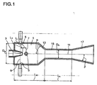
- the sole figure shows a device for mixing amine and phosgene in the liquid phase.
- An apparatus for mixing amine and phosgene comprises a mixing chamber 1 into which phosgene and amine are fed. Through an opening 3, which is arranged coaxially to the mixing chamber 1, the amine is preferably added. Alternatively, however, it is also possible for the phosgene to be fed through the opening 3 arranged coaxially with the mixing chamber. However, it is preferable to add the amine through the orifice 3 coaxial with the mixing chamber.
- the orifice 3, which is coaxial with the mixing chamber 1, is formed in the form of a nozzle projecting into the mixing chamber 1 as shown.
- the supply openings 5 are also preferably formed as nozzles.
- the feed openings 5 are arranged in at least two planes 7, 9, which are arranged perpendicular to the axis of the mixing chamber.
- the levels 7, 9 are shown here by dashed lines.
- the supply openings 5 are arranged in two planes 7, 9.
- a first level 7 is arranged downstream of the coaxially arranged opening 3 and a second level 9 upstream.
- the supply openings 5 are arranged in more than two planes.
- the supply openings 5 are arranged in more than two levels 7, 9, in each case at least one level upstream and at least one level downstream of the coaxially arranged opening 3 is arranged.
- two feed openings 5 are arranged in each plane 7, 9, wherein the feed openings 5 are diametrically opposed in each case. Due to the arrangement in which the supply openings 5 are diametrically opposed, the main directions of the supply openings 5 meet in the axis 11 of the mixing chamber 1.
- the ratio of the distance L 1 of the first plane 7 to the coaxially arranged to the mixing chamber opening 3 based on the diameter D M of the mixing chamber 1 is preferably in the range of 0 to 1, more preferably in the range of 0.01 to 0.5 and in particular Range from 0.05 to 0.2.
- supply ports 5 are disposed in more than one plane downstream of the coaxial with the mixing chamber arranged opening 3, this is the distance of the plane which is the coaxial with the mixing chamber arranged opening 3 closest.
- the ratio of the distance L 2 of the second plane 9, which is arranged upstream of the coaxial with the mixing chamber 1 arranged opening 3, based on the diameter D M of the mixing chamber 1 is also preferably in the range of 0 to 1, more preferably in the range of 0.01 to 0.5 and in particular in the range of 0.05 to 0.2. If supply openings 5 are arranged in more than two levels upstream of the opening 3 coaxial with the mixing chamber 1, this corresponds to the distance of the plane closest to the opening 3.
- the mixing chamber 1 has a diameter constriction 13.
- the diameter constriction 13 is preferably conical and designed with an angle ⁇ in the range of 10 to 80 °, preferably at an angle in the range of 15 to 60 ° and particularly preferably at an angle of 18 to 40 ° to the axis 11 of the mixing chamber 1.
- the diameter constriction 13 is followed by a zone of constant diameter 15.
- the zone 15 of constant diameter has a diameter D A , wherein the ratio of the diameter D A of the zone 15 of constant diameter to the diameter D M of the mixing chamber 1 as already described above in the range of 0.2 to 0.7, more preferably in the range from 0.25 to 0.65 and especially in the range of 0.3 to 0.6.
- the diameter constriction 13 the diameter decreases from the diameter D M of the mixing chamber 1 to the diameter D A of the zone 15 of constant diameter.
- the zone 15 of constant diameter is followed by a cross-sectional widening 17.
- the cross-sectional widening 17 is preferably designed in the form of a diffuser.
- the cross-sectional widening 17 has an opening angle ⁇ , which is selected so that in the cross-sectional widening 17 no separation of the flow occurs.
- ⁇ opening angle
- the diameter in the cross-sectional widening 17 is gradually expanded. In this case, between the individual stages, in which the diameter is widened, in each case a region of constant diameter is arranged. Alternatively, it is also possible that in each case an area is formed between the individual stages, in which the diameter widens conically.
- the cross-sectional enlargement 17 is particularly preferably conical and the opening angle ⁇ of the cross-sectional widening 17 is preferably ⁇ 15 °, more preferably ⁇ 10 ° and particularly preferably ⁇ 8 °.
- the length of the cross-sectional widening 17 is chosen such that the diameter widens to the diameter of the reactor adjoining the apparatus for mixing the amine and phosgene, which is not shown here.
- the ratio of the length L M of the mixing chamber 1 with respect to the diameter D M is preferably in the range between 1 and 2 and in particular in the range from 1 to 1.5.
- the ratio of the length L A of the zone 15 of constant diameter with respect to the diameter D A of the zone of constant diameter is preferably in the range of 1 to 10, more preferably in the range of 1.5 to 9 and in particular in the range of 2 to 8.
- a device which comprises a mixing chamber with a diameter of 40 mm and a length of 66 mm.
- an amine supply means which projects 26 mm into the mixing chamber, opens with a diameter of 20 mm and a nozzle diameter of 5.5 mm.
- two feed openings are arranged diametrically 6 mm above the outlet cross section of the central nozzle and two feed openings diametrically 6 mm below the outlet cross section of the central nozzle.
- the diameter of the feed openings above the exit cross section of the central nozzle is 5.1 mm with a diameter of the feeder of 15 mm and the nozzle diameter of the feed openings below, i. downstream of the opening of the central nozzle is 6.9 mm with a diameter of the feeder of 20 mm.
- the mixing chamber has a conical constriction at an angle of 25 °, the diameter of the mixing chamber diameter of 40 mm to the outlet diameter of 25 mm decreases.
- the total length of the mixing chamber comprising the cylindrical part and the conical part is 66 mm.
- the mixing chamber is followed by a zone of constant diameter with a length of 180 mm.
- the zone of constant diameter is followed by an extension with an opening angle of 6 °. With the extension of the diameter increases to the diameter of the subsequent tubular reactor.
- amine-containing material stream 3.75 m 3 / h of an amine-containing material stream are fed via the central nozzle and 11.2 m 3 / h of a phosgene-containing stream via the feed openings.
- the amine-containing stream contains from 34 to 36% by weight of MDA / PMDA in an amount of from 50.4 to 51.1% by weight of MDA and from 54 to 56% by weight of monochlorobenzene, and the phosgene-containing stream contains from 66 to 70% by weight. % Phosgene and 30 to 34% by weight monochlorobenzene.
- the residence time in the mixing zone is 17 ms.
- the residence time in the constant diameter zone is approximately 21 ms.
Landscapes
- Chemical & Material Sciences (AREA)
- Organic Chemistry (AREA)
- Chemical Kinetics & Catalysis (AREA)
- Organic Low-Molecular-Weight Compounds And Preparation Thereof (AREA)
Description
- Die Erfindung betrifft ein Verfahren zur Herstellung von Isocyanaten durch Umsetzung der korrespondierenden Amine mit Phosgen in der Flüssigphase, gegebenenfalls in Gegenwart mindestens eines Inertmediums, bei dem zunächst das Amin und das Phosgen in einer Mischkammer zu einem Reaktionsgemisch gemischt werden und das Reaktionsgemisch einem Reaktor zugeführt wird. Das Amin wird durch eine koaxial zur Mischkammer angeordnete Öffnung zugegeben und das Phosgen durch Zufuhröffnungen in mindestens zwei senkrecht zur Achse der Mischkammer angeordneten Ebenen. Mindestens eine Ebene ist in Hauptströmungsrichtung des Reaktionsgemischs stromauf und eine Ebene stromab zur Öffnung der Zugabe des Amins angeordnet.
- Die Herstellung von Isocyanaten durch Phosgenierung der korrespondierenden Amine kann prinzipiell durch eine FLüssigphasen- oder eine Gasphasenphosgenierung erfolgen. Die Flüssigphasenphosgenierung zeichnet sich dadurch aus, dass die Reaktion bei niedrigeren Temperaturen als die Gasphasenphosgenierung durchgeführt werden kann und eine Verdampfung der Edukte nicht erforderlich ist.
- Bei der Flüssigphasenphosgenierung wird ein aminhaltiger Eduktstrom in der Flüssigphase zugeführt. Dieser wird mit einem phosgenhaltigen Eduktstrom vermischt. Hierbei kann das Phosgen in einem inerten Lösungsmittel gelöst sein. Anschließend wird der phosgenhaltige Eduktstrom in eine Mischkammer eingespritzt, in der dieser mit dem aminhaltigen Eduktstrom vermischt wird. Das Amin und das Phosgen setzen sich unter Freisetzung von HCl zu den entsprechenden Isocyanaten um.
- Eine schnelle Vermischung des Amins mit dem Phosgen ist notwendig, da das entstehende Isocyanat bei einer zu niedrigen Phosgenkonzentration mit dem überschüssigen Amin zu Harnstoff bzw. anderen störenden, hochviskosen und festen Nebenprodukten reagiert. Aus diesem Grund ist eine schnelle Vermischung und eine kurze Verweilzeit in der Reaktionskammer erforderlich.
- Eine Vorrichtung, bei der das Amin und das Phosgen zunächst in einer Mischkammer zu einem Reaktionsgemisch gemischt werden und das Reaktionsgemisch anschließend einem Reaktor zugeführt wird, wobei das Amin durch eine koaxial zur Mischkammer angeordnete Öffnung zugegeben wird und das Phosgen durch Zufuhröffnungen in mindestens zwei senkrecht zur Achse der Mischkammer angeordneten Ebenen zugegeben wird, ist zum Beispiel aus
DD-A 300 168 - Aufgabe der vorliegenden Erfindung ist es, ein Verfahren zur Herstellung von Isocyanaten durch Umsetzung der korrespondierenden Amine mit Phosgen in der Flüssigphase bereitzustellen, bei dem eine im Vergleich zu den aus dem Stand der Technik bekannten Verfahren geringere Nebenkomponentenbildung erreicht werden kann.
- Gelöst wird die Aufgabe durch ein Verfahren zur Herstellung von Isocyanaten durch Umsetzung der korrespondierenden Amine mit Phosgen in der Flüssigphase, gegebenenfalls in Gegenwart mindestens eines Inertmediums, bei dem zunächst das Amin und das Phosgen in einer Mischkammer zu einem Reaktionsgemisch gemischt werden und das Reaktionsgemisch einem Reaktor zugeführt wird. Das Amin wird durch eine koaxial zur Mischkammer angeordnete Öffnung zugegeben und das Phosgen wird durch Zufuhröffnungen in mindestens zwei senkrecht zur Achse der Mischkammer angeordneten Ebenen zugegeben. Dabei ist mindestens eine Ebene in Hauptströmungsrichtung des Reaktionsgemischs stromauf und eine Ebene stromab zur Öffnung der Zugabe des Amins angeordnet. Die mittlere Verweilzeit des Reaktionsgemischs in der Mischkammer beträgt erfindungsgemäß maximal 18,5 ms.
- Durch die kurze Verweilzeit des Reaktionsgemischs in der Mischkammer von maximal 18,5 ms kann eine im Vergleich zu den aus dem Stand der Technik bekannten Verfahren reduzierte Nebenkomponentenbildung erzielt werden.
- Die mittlere Verweilzeit in der Mischkammer ergibt sich dabei aus

- Darin bedeuten ts die Verweilzeit, V das Volumen der Mischkammer und V* den Gesamtvolumenstrom der Eduktströme. Das Volumen der Mischkammer ist dabei das Volumen bis zum Ende der Verengung, das heißt, bis zum Eintritt in die sich an die Mischkammer anschließende Zone mit konstantem Querschnitt. Das Volumen der zentralen Düse, die in die Mischkammer ragt ist nicht Teil des Volumens der Mischkammer.
- Das zur Herstellung von Isocyanaten eingesetzte Amin ist zum Beispiel ein Monoamin, ein Diamin, ein Triamin oder höherwertiges Amin. Bevorzugt werden jedoch Monoamine oder Diamine eingesetzt. Entsprechend des eingesetzten Amins ergeben sich die korrespondierenden Monoisocyanate, Diisocyanate, Triisocyanate oder höherwertigen Isocyanate. Bevorzugt werden Monoisocyanate oder Diisocyanate mit dem erfindungsgemäßen Verfahren hergestellt.
- Die Amine und Isocyanate können aliphatisch, cycloaliphatisch oder aromatisch sein. Cycloaliphatische Isocyanate sind solche, die mindestens ein cycloaliphatisches Ringsystem enthalten.
- Aliphatische Isocyanate sind solche, die ausschließlich Isocyanatgruppen aufweisen, die an gerade oder verzweigte Ketten gebunden sind.
- Aromatische Isocyanate sind solche, die mindestens eine an mindestens ein aromatisches Ringsystem gebundene Isocyanatgruppe aufweisen.
- (Cyclo)aliphatische Isocyanate stehen im Rahmen dieser Anmeldung kurz für cycloaliphatische und/oder aliphatische Isocyanate.
- Beispiele für aromatische Diisocyanate sind monomeres 2,4'- oder 4,4'-Methylen-di(phenylisocyanat) (MDI) sowie dessen höhere Oligomere (PMDI) bzw. Mischungen daraus, 2,4- und/oder 2,6-Toluylendiisocyanat (TID) und 1,5- oder 1,8-Naphthyldiisocyanat (NDI).
- Bevorzugte (cyclo)aliphatische Diisocyanate sind solche mit 4 bis 20 C-Atomen.
- Beispiele für übliche aliphatische Diisocyanate sind 1,4-Tetramethylendiisocyanat, Hexamethylendiisocyanat (1,6-Diisocyanatohexan), 1,8-Octamethylendiisocyanat, 1,10-Decamethylendiisocyanat, 1,12-Dodecamethylendiiso-cyanat, 1,14-Tetradecamethylendiisocyanat, Derivate des Lysindiisocyanats, Tetramethylxylylendiisocyanat (TMXDI), Trimethylhexandiisocyanat oder Tetramethylhexandiisocyanat, sowie 3 (bzw. 4)-, 8 (bzw. 9)-Bis(isocyanatomethyl)-tricyclo[5.2.1.02,6]decan-Isomerengemische, sowie cycloaliphatische Diisocyanate, wie 1,4-, 1,3- oder 1,2-Diisocyanatocyclohexan, 4,4'- oder 2,4'-Di(isocyanatocyclo-hexyl)methan, 1-Isocyanato-3,3,5-trimethyl-5-(isocyanatomethyl)cyclohexan (Isophorondiisocyanat), 1,3- oder 1,4-bis(Isocyanatomethyl)cyclohexan, 2,4-, oder 2,6-Diiso-cyanato-1-methylcyclohexan.
- Besonders bevorzugt sind MDI/PMDI-Isomeren- und -Oligomerengemische sowie TDI-Isomerengemische.
- Zur Herstellung von Monoisocyanaten können ebenfalls aliphatische, cycloaliphatische oder aromatische Amine eingesetzt werden. Als aromatisches Amin ist insbesondere Anilin bevorzugt.
- Das Phosgen kann vor Zugabe in die Mischkammer in einem inerten Lösungsmittel gelöst sein. Als inerte Lösungsmittel, in denen das Phosgen gelöst wird, eignen sich zum Beispiel chlorierte aromatische Kohlenwasserstoffe, beispielsweise Monochlorbenzol oder Dichlorbenzol, oder auch Toluol. Das Verhältnis von Phosgen zu inertem Lösungsmittel liegt bevorzugt im Bereich von 1:0 bis 1:2, insbesondere im Bereich von 1:0 bis 1:1.
- In einer bevorzugten Ausführungsform wird das Phosgen über jeweils mindestens zwei Zufuhröffnungen in den mindestens zwei senkrecht zur Achse der Mischkammer angeordneten Ebenen zugegeben. Die Zufuhröffnungen, durch die das Phosgen zugegeben wird, sind dabei vorzugsweise so angeordnet, dass sich die Hauptrichtungen der Zufuhröffnungen in der Achse der Mischkammer treffen. Durch die Anordnung der Zufuhröffnungen derart, dass sich die Hauptrichtungen in der Achse der Mischkammer treffen, treffen die über die Zufuhröffnungen zugegebenen Phosgenstrahlen direkt auf das Amin, das durch die koaxial zur Mischkammer angeordnete Öffnung zugegeben wird. Hierdurch wird eine schnelle Vermischung von Phosgen und Amin realisiert. Insbesondere treffen auch Phosgenstrahlen, die die Zufuhröffnungen verlassen, an der Achse der Mischkammer zusammen. Hierdurch ergibt sich in Strömungsrichtung des Amins eine gleichmäßige Phosgenverteilung.
- Weiterhin ist es bevorzugt, wenn die Zufuhröffnungen der ersten Ebene zu den Zufuhröffnungen der zweiten Ebene um die Achse der Mischkammer gedreht angeordnet sind. Besonders bevorzugt ist es, wenn die Zufuhröffnungen bei jeweils zwei Zufuhröffnungen pro Ebene um 90 Grad zueinander gedreht angeordnet sind.
- Die Mischkammer, in der das Amin mit dem Phosgen gemischt wird, weist vorzugsweise ein Verhältnis von Länge zu Durchmesser (UD-Verhältnis) auf, das im Bereich von 1 bis 2 und insbesondere im Bereich von 1 bis 1,5 liegt. Die koaxial zur Achse der Mischkammer angeordnete Öffnung, über die das Amin zugegeben wird, ragt vorzugsweise in die Mischkammer hinein. Hierzu ist die Öffnung, über die das Amin zugegeben wird, zum Beispiel als Düse ausgebildet. Die Öffnung, über die das Amin zugegeben wird, ist dann die Austrittsöffnung der Düse. Das Verhältnis des Durchmessers der Öffnung, über die das Amin zugegeben wird bezogen auf den Durchmesser der Mischkammer liegt vorzugsweise im Bereich von 0,05 bis 0,5, mehr bevorzugt im Bereich von 0,1 bis 0,4 und insbesondere im Bereich von 0,15 bis 0,35.
- Wenn das Phosgen durch Zufuhröffnungen in zwei senkrecht zur Achse der Mischkammer angeordneten Ebenen zugegeben wird, wobei eine Ebene in Hauptströmungsrichtung des Reaktionsgemischs stromauf und eine Ebene stromab zur Öffnung zur Zugabe des Amins angeordnet ist, so liegt das Verhältnis des Abstandes der Ebene, die stromab zur Öffnung, durch die das Amin zugegeben wird, angeordnet ist, zur Öffnung, durch die das Amin zugegeben wird, bezogen auf den Durchmesser der Mischkammer im Bereich von 0 bis 1, mehr bevorzugt im Bereich von 0,01 bis 0,5 und insbesondere im Bereich von 0,05 bis 0,2. Wenn das Phosgen durch Zufuhröffnungen in mehr als einer senkrecht zur Achse der Mischkammer angeordneten Ebene zugegeben wird, die in Hauptströmungsrichtung des Reaktionsgemischs stromab der Öffnung, durch die das Amin zugegeben wird, angeordnet sind, so ist der Abstand der Zufuhröffnungen der Ebene, die der Öffnung, über die das Amin zugegeben wird, am nächsten liegt, entsprechend dem Abstand der Ebene der Zufuhröffnungen, wenn nur eine Ebene stromab zur Öffnung, über die das Amin zugegeben wird, angeordnet ist.
- Wenn das Phosgen durch Zufuhröffnungen in zwei senkrecht zur Achse der Mischkammer angeordneten Ebenen zugegeben wird, wobei eine Ebene in Hauptströmungsrichtung des Reaktionsgemischs stromauf und eine Ebene stromab zur Öffnung zur Zugabe des Amins angeordnet ist, so liegt das Verhältnis des Abstandes der Ebene, die stromauf zur Öffnung, durch die das Amin zugegeben wird, angeordnet ist, zur Öffnung, durch die das Amin zugegeben wird, bezogen auf den Durchmesser der Mischkammer im Bereich von 0 bis 1, mehr bevorzugt im Bereich von 0,01 bis 0,5 und insbesondere im Bereich von 0,05 bis 0,2. Wenn das Phosgen durch Zufuhröffnungen in mehr als einer senkrecht zur Achse der Mischkammer angeordneten Ebene zugegeben wird, die in Hauptströmungsrichtung des Reaktionsgemischs stromauf der Öffnung, durch die das Amin zugegeben wird, angeordnet sind, so ist der Abstand der Zufuhröffnungen der Ebene, die der Öffnung, über die das Amin zugegeben wird, am nächsten liegt, entsprechend dem Abstand der Ebene der Zufuhröffnungen, wenn nur eine Ebene stromauf zur Öffnung, über die das Amin zugegeben wird, angeordnet ist.
- Bevorzugt wird das Phosgen durch Zufuhröffnungen in maximal fünf senkrecht zur Achse der Mischkammer angeordneten Ebenen zugegeben. Mehr bevorzugt ist es, wenn das Phosgen durch Zufuhröffnungen in maximal drei senkrecht zur Achse der Mischkammer angeordnete Ebenen zugegeben wird und besonders bevorzugt, wenn das Phosgen durch Zufuhröffnungen in zwei senkrecht zur Achse der Mischkammer angeordneten Ebenen zugegeben wird.
- Die Anzahl der Zufuhröffnungen in den einzelnen Ebenen ist vorzugsweise maximal fünf, mehr bevorzugt maximal vier und insbesondere zwei. Durch die Anzahl der Zufuhröffnungen in den einzelnen Ebenen ergibt sich eine gute Verteilung des Phosgens in der Mischkammer. Hierbei ist es weiterhin bevorzugt, wenn die Öffnungen der einzelnen Ebenen gegeneinander verdreht sind, so dass die Zufuhröffnungen der einzelnen Ebenen in Strömungsrichtung nicht fluchtend sind. Bei Zufuhröffnungen in mehr als zwei Ebenen sind die Zufuhröffnungen der einzelnen Ebenen vorzugsweise gleichmäßig zueinander gedreht. Der Winkel, um den die einzelnen Ebenen zueinander gedreht sind, errechnet sich dabei vorzugsweise zu

wobei α der Winkel ist, um den die Ebenen zueinander gedreht sind und zδ die Anzahl der Öffnungen je Ebene. - Der Durchmesser der Zufuhröffnungen, durch die das Phosgen zugegeben wird, ist vorzugsweise kleiner als der Abstand der Ebenen, in denen die Zufuhröffnungen angeordnet sind. Bevorzugt liegt der Durchmesser der Zufuhröffnungen bezogen auf den Durchmesser der Mischkammer im Bereich von 0,01 bis 0,5, mehr bevorzugt im Bereich von 0,02 bis 0,3 und insbesondere im Bereich von 0,03 bis 0,25.
- Die Zufuhröffnungen können in jedem beliebigen Winkel in die Mischkammer münden. Vorzugsweise schneiden sich die Achsen der Zufuhröffnungen mit der Achse der Mischkammer, besonders bevorzugt münden die Zufuhröffnungen mit einem Winkel von 90° in die Mischkammer.
- Die Zufuhröffnungen, durch die das Phosgen zugegeben wird, sind vorzugsweise Düsenöffnungen. Das heißt, dass das Phosgen der Mischkammer über Leitungen zugeführt wird und am Ende der Leitungen eine Querschnittsverengung in Form einer Düse ausgebildet ist. Aus der Düse tritt das Phosgen dann in die Mischkammer ein. Die Zufuhröffnung des Phosgens ist dabei vorzugsweise bündig mit der Wandung der Mischkammer. Die Düsen können sowohl kreisrunde als auch von der kreisrunden Form abweichende Öffnungen aufweisen.
- Die Mischkammer, in der das Amin mit dem Phosgen vermischt wird, ist vorzugsweise rotationssymmetrisch. Wenn die Mischkammer keinen kreisförmigen Querschnitt hat, so ist als Durchmesser der Mischkammer immer der hydraulische Durchmesser gemeint.
- An ihrem stromabwärtigen Ende weist die Mischkammer vorzugsweise eine Durchmesserverengung auf, durch die eine Rückvermischung des Reaktionsgemischs erfolgt. Die Rückvermischung ergibt sich durch die Umlenkung der Strömung aufgrund der Durchmesserverengung.
- Die Durchmesserverengung am stromabwärtigen Ende der Mischkammer ist vorzugsweise mit einem Winkel im Bereich von 10 bis 80° zur Achse der Mischkammer ausgeführt. Mehr bevorzugt ist die Durchmesserverengung am stromabwärtigen Ende mit einem Winkel von 15 bis 60° und besonders bevorzugt mit einem Winkel von 18 bis 40° zur Achse der Mischkammer ausgeführt. Die Durchmesserverengung am stromabwärtigen Ende der Mischkammer ist vorzugsweise eine konische Verengung. Das Verhältnis des Durchmessers der Durchmesserverengung, auf die der Querschnitt reduziert wird, liegt bezogen auf den Durchmesser der Mischkammer im Bereich von 0,2 bis 0,7, mehr bevorzugt im Bereich von 0,25 bis 0,65 und insbesondere im Bereich von 0,3 bis 0,6. Neben einer Rückvermischung erfolgt durch die Durchmesserverengung somit auch eine Beschleunigung des Reaktionsgemischs.
- Zur Strömungsvergleichmäßigung schließt sich an die Durchmesserverengung vorzugsweise eine Zone mit einem konstanten Durchmesser an, in der nur eine geringe Rückvermischung erfolgt.
- Die Verweilzeit des Reaktionsgemischs in der Zone mit konstantem Durchmesser beträgt vorzugsweise maximal 50 ms, insbesondere maximal 30 ms. Die Länge der Zone mit konstantem Durchmesser bezogen auf den Durchmesser dieser Zone (UD-Verhältnis) liegt vorzugsweise im Bereich von 1 bis 10, mehr bevorzugt im Bereich von 1,5 bis 9 und insbesondere im Bereich von 2 bis 8.
- An die Zone mit konstantem Durchmesser schließt sich eine Zone mit einer Querschnittserweiterung an, wobei die Querschnittserweiterung einen Öffnungswinkel bezogen auf die Achse der Zone aufweist, bei dem keine Ablösung der Strömung erfolgt. Das bedeutet, dass die Querschnittserweiterung in Form eines Diffusors ausgebildet ist. Die Querschnittserweiterung erweitert den Durchmesser, bis der Durchmesser des vorzugsweise als Rohrreaktor ausgebildeten Reaktors erreicht ist. Hierbei ist es möglich, dass der Durchmesser stufenweise erweitert wird, wobei sich zwischen die einzelnen Stufen, in denen der Durchmesser erweitert wird, jeweils ein Bereich mit konstantem Durchmesser angeordnet ist.
- Um das Ablösen der Strömung zu verhindern, ist der Öffnungswinkel der Querschnittserweiterung zur Achse der Zone vorzugsweise kleiner als 15°, mehr bevorzugt kleiner als 10° und besonders bevorzugt kleiner als 8°.
- Ein Ausführungsbeispiel der Erfindung ist anhand der Zeichnung dargestellt und wird in der nachfolgenden Beschreibung näher erläutert.
- Die einzige Figur zeigt eine Vorrichtung zum Mischen von Amin und Phosgen in der Flüssigphase.
- Bei Verfahren zur Herstellung von Isocyanaten durch Umsetzung der korrespondierenden Amine mit Phosgen in der Flüssigphase wird das Amin mit dem Phosgen vermischt, bevor die vermischten Edukte einem Reaktor, in dem die Umsetzung erfolgt, zugeführt werden.
- Eine Vorrichtung zum Mischen von Amin und Phosgen umfasst eine Mischkammer 1, in die Phosgen und Amin zugeführt werden. Durch eine Öffnung 3, die koaxial zur Mischkammer 1 angeordnet ist, wird vorzugsweise das Amin zugegeben. Alternativ ist es jedoch auch möglich, dass durch die koaxial zur Mischkammer angeordnete Öffnung 3 das Phosgen zugeführt wird. Bevorzugt ist jedoch die Zugabe des Amins über die koaxial zur Mischkammer angeordnete Öffnung 3. Die koaxial zur Mischkammer 1 angeordnete Öffnung 3 ist z.B., wie hier dargestellt, in Form einer Düse ausgebildet, die in die Mischkammer 1 ragt.
- Weiterhin umfasst die Vorrichtung zur Mischung von Phosgen und Amin Zufuhröffnungen 5, durch die das Phosgen bzw. bei Zugabe des Phosgens über die koaxial zur Achse der Mischkammer angeordnete Öffnung das Amin zugegeben wird. Die Zufuhröffnungen 5 sind ebenfalls vorzugsweise als Düsen ausgebildet. Die Zufuhröffnungen 5 sind in mindestens zwei Ebenen 7, 9, die senkrecht zur Achse der Mischkammer angeordnet sind, angeordnet. Die Ebenen 7, 9 sind hier durch gestrichelte Linien dargestellt. In der hier dargestellten Ausführungsform sind die Zufuhröffnungen 5 in zwei Ebenen 7, 9 angeordnet. Eine erste Ebene 7 ist dabei stromab zur koaxial angeordneten Öffnung 3 angeordnet und eine zweite Ebene 9 stromauf.
- Neben der hier dargestellten Ausführungsform mit zwei Ebenen 7, 9, in denen die Zufuhröffnungen 5 angeordnet sind, ist es alternativ auch möglich, dass die Zufuhröffnungen in mehr als zwei Ebenen angeordnet sind. In dem Fall, dass die Zufuhröffnungen 5 in mehr als zwei Ebenen 7, 9 angeordnet sind, ist jeweils mindestens eine Ebene stromauf und mindestens eine Ebene stromab der koaxial angeordneten Öffnung 3 angeordnet.
- Bevorzugt sind in jeder Ebene 7, 9 zwei Zufuhröffnungen 5 angeordnet, wobei sich die Zufuhröffnungen 5 jeweils diametral gegenüberliegen. Durch die Anordnung, bei der die Zufuhröffnungen 5 diametral gegenüberliegen, treffen sich die Hauptrichtungen der Zufuhröffnungen 5 in der Achse 11 der Mischkammer 1.
- Das Verhältnis des Abstandes L1 der ersten Ebene 7 zur koaxial zur Mischkammer angeordneten Öffnung 3 bezogen auf den Durchmesser DM der Mischkammer 1 liegt vorzugsweise im Bereich von 0 bis 1, mehr bevorzugt im Bereich von 0,01 bis 0,5 und insbesondere im Bereich von 0,05 bis 0,2. Wenn Zufuhröffnungen 5 in mehr als einer Ebene stromab zur koaxial zur Mischkammer angeordneten Öffnung 3 angeordnet sind, so ist dies der Abstand der Ebene, die der koaxial zur Mischkammer angeordneten Öffnung 3 am nächsten liegt.
- Das Verhältnis des Abstandes L2 der zweiten Ebene 9, die stromauf zur koaxial zur Mischkammer 1 angeordneten Öffnung 3 angeordnet ist, bezogen auf den Durchmesser DM der Mischkammer 1 liegt ebenfalls vorzugsweise im Bereich von 0 bis 1, mehr bevorzugt im Bereich von 0,01 bis 0,5 und insbesondere im Bereich von 0,05 bis 0,2. Wenn Zufuhröffnungen 5 in mehr als zwei Ebenen stromauf zur koaxial zur Mischkammer 1 angeordneten Öffnung 3 angeordnet sind, so entspricht dies dem Abstand der Ebene, die der Öffnung 3 am nächsten liegt.
- An ihrem stromabwärtigen Ende weist die Mischkammer 1 eine Durchmesserverengung 13 auf. Die Durchmesserverengung 13 ist vorzugsweise konisch ausgebildet und mit einem Winkel α im Bereich von 10 bis 80°, bevorzugt mit einem Winkel im Bereich von 15 bis 60° und besonders bevorzugt mit einem Winkel von 18 bis 40° zur Achse 11 der Mischkammer 1 ausgeführt.
- An die Durchmesserverengung 13 schließt sich eine Zone konstanten Durchmessers 15 an. Die Zone 15 konstanten Durchmessers weist einen Durchmesser DA auf, wobei das Verhältnis des Durchmessers DA der Zone 15 konstanten Durchmessers zum Durchmesser DM der Mischkammer 1 wie vorstehend bereits beschrieben im Bereich von 0,2 bis 0,7, mehr bevorzugt im Bereich von 0,25 bis 0,65 und insbesondere im Bereich von 0,3 bis 0,6 liegt. Mit der Durchmesserverengung 13 nimmt der Durchmesser vom Durchmesser DM der Mischkammer 1 auf den Durchmesser DA der Zone 15 konstanten Durchmessers ab.
- An die Zone 15 konstanten Durchmessers schließt sich eine Querschnittserweiterung 17 an. Die Querschnittserweiterung 17 ist dabei vorzugsweise in Form eines Diffusors ausgebildet. Die Querschnittserweiterung 17 weist einen Öffnungswinkel β auf, der so ausgewählt ist, dass in der Querschnittserweiterung 17 keine Ablösung der Strömung auftritt. Alternativ zur hier dargestellten Ausführungsform mit einer sich konisch erweiternden Querschnittserweiterung 17 ist es z.B. auch möglich, dass der Durchmesser in der Querschnittserweiterung 17 stufenweise erweitert wird. In diesem Fall ist zwischen den einzelnen Stufen, in denen der Durchmesser erweitert wird, jeweils ein Bereich mit konstantem Durchmesser angeordnet. Alternativ ist es auch möglich, dass zwischen den einzelnen Stufen jeweils ein Bereich ausgebildet ist, in dem sich der Durchmesser konisch erweitert.
- Besonders bevorzugt ist die Querschnittserweiterung 17 jedoch konisch ausgebildet und der Öffnungswinkel β der Querschnittserweiterung 17 ist vorzugsweise < 15°, mehr bevorzugt < 10° und besonders bevorzugt < 8°.
- Die Länge der Querschnittserweiterung 17 ist so gewählt, dass sich der Durchmesser auf den Durchmesser des sich an die Vorrichtung zur Vermischung des Amins und Phosgens anschließenden Reaktors erweitert, der hier nicht dargestellt ist.
- Um eine kurze Verweilzeit und hohe Mischgeschwindigkeiten in der Mischkammer 1 zu erzielen, ist das Verhältnis der Länge LM der Mischkammer 1 bezogen auf den Durchmesser DM vorzugsweise im Bereich zwischen 1 und 2 und insbesondere im Bereich von 1 bis 1,5. Das Verhältnis der Länge LA der Zone 15 konstanten Durchmessers bezogen auf den Durchmesser DA der Zone konstanten Durchmessers liegt vorzugsweise im Bereich von 1 bis 10, mehr bevorzugt im Bereich von 1,5 bis 9 und insbesondere im Bereich von 2 bis 8.
- Zur Herstellung von MDI/PMDI wird eine Vorrichtung eingesetzt, die eine Mischkammer mit einem Durchmesser von 40 mm und einer Länge von 66 mm umfasst. In die Mischkammer mündet eine Zuführungseinrichtung für das Amin, die 26 mm in die Mischkammer hineinragt, mit einem Durchmesser von 20 mm und einem Düsendurchmesser von 5,5 mm. Zur Zufuhr des Phosgen sind zwei Zufuhröffnungen diametral 6 mm oberhalb vom Austrittsquerschnitt der zentralen Düse und zwei Zufuhröffnungen diametral 6 mm unterhalb vom Austrittsquerschnitt der zentralen Düse angeordnet. Der Durchmesser der Zufuhröffnungen oberhalb des Austrittsquerschnitts der zentralen Düse beträgt 5,1 mm bei einem Durchmesser der Zufuhreinrichtung von 15 mm und der Düsendurchmesser der Zufuhröffnungen unterhalb, d.h. stromab der Öffnung der zentralen Düse, beträgt 6,9 mm bei einem Durchmesser der Zufuhreinrichtung von 20 mm.
- Die Mischkammer weist eine konische Verengung mit einem Winkel von 25° auf, wobei der Durchmesser vom Mischkammerdurchmesser von 40 mm auf den Austrittsdurchmesser von 25 mm abnimmt. Die Gesamtlänge der Mischkammer umfassend den zylindrischen Teil und den konischen Teil beträgt 66 mm. An die Mischkammer schließt sich eine Zone konstanten Durchmessers mit einer Länge von 180 mm an. An die Zone konstanten Durchmessers schließt sich eine Erweiterung mit einem Öffnungswinkel von 6° an. Mit der Erweiterung nimmt der Durchmesser auf den Durchmesser des nachfolgenden Rohrreaktors zu.
- Über die zentrale Düse werden 3,75 m3/h eines aminhaltigen Stoffstroms und über die Zufuhröffnungen 11,2 m3/h eines phosgenhaltigen Stroms zugeführt. Der aminhaltige Strom enthält 34 bis 36 Gew.-% MDA/PMDA mit einem Anteil von 50,4 bis 51,1 Gew.-% MDA und 54 bis 56 Gew.-% Monochlorbenzen und der phosgenhaltige Strom enthält 66 bis 70 Gew.-% Phosgen und 30 bis 34 Gew.-% Monochlorbenzen.
- Die Verweilzeit in der Mischzone beträgt 17 ms. Die Verweilzeit in der Zone mit konstantem Durchmesser beträgt ungefähr 21 ms.
-
1 Mischkammer 3 Öffnung koaxial zur Mischkammer 5 Zufuhröffnung 7 erste Ebene 9 zweite Ebene 11 Achse 13 Durchmesserverengung 15 Zone konstanten Durchmessers 17 Querschnittserweiterung DA Durchmesser der Zone 15 konstanten Durchmessers DM Durchmesser der Mischkammer 1 LA Länge der Zone 15 konstanten Durchmessers LM Länge der Mischkammer 1 L1 Abstand der ersten Ebene 7 zur Öffnung 3 L2 Abstand der zweiten Ebene 9 zur Öffnung 3 α Winkel in dem die Durchmesserverengung 13 ausgeführt ist β Öffnungswinkel der Querschnittserweiterung 17
Claims (13)
- Verfahren zur Herstellung von Isocyanaten durch Umsetzung der korrespondierenden Amine mit Phosgen in der Flüssigphase, gegebenenfalls in Gegenwart mindestens eines Inertmediums, bei dem zunächst das Amin und das Phosgen in einer Mischkammer (1) zu einem Reaktionsgemisch gemischt werden und das Reaktionsgemisch einem Reaktor zugeführt wird, wobei das Amin durch eine koaxial zur Mischkammer (1) angeordnete Öffnung (3) zugegeben wird und das Phosgen durch Zufuhröffnungen (5) in mindestens zwei senkrecht zur Achse der Mischkammer angeordneten Ebenen (7, 9) zugegeben wird oder das Phosgen durch die koaxial zur Mischkammer angeordnete Öffnung (3) und das Amin durch die Zufuhröffnungen (5) in mindestens zwei senkrecht zur Achse (11) der Mischkammer (1) angeordneten Ebenen (7, 9) zugegeben werden, wobei mindestens eine Ebene (9) in Hauptströmungsrichtung des Reaktionsgemischs stromauf und mindestens eine Ebene (7) stromab zur Öffnung (3) zur Zugabe des Amins angeordnet ist, dadurch gekennzeichnet, dass die mittlere Verweilzeit des Reaktionsgemischs in der Mischkammer (1) maximal 18,5 ms beträgt.
- Verfahren gemäß Anspruch 1, dadurch gekennzeichnet, dass das Phosgen über jeweils mindestens zwei Zufuhröffnungen (5) in den mindestens zwei senkrecht zur Achse der Mischkammer angeordneten Ebenen (7, 9) zugegeben wird.
- Verfahren gemäß Anspruch 2, dadurch gekennzeichnet, dass die Zufuhröffnungen (5), durch die das Phosgen zugegeben wird, so angeordnet sind, dass sich die Hauptrichtungen der Zufuhröffnungen (5) in der Achse (11) der Mischkammer (1) treffen.
- Verfahren gemäß einem der Ansprüche 1 bis 3, dadurch gekennzeichnet, dass die Mischkammer (1) an ihrem stromabwärtigen Ende eine Durchmesserverengung (13) aufweist, durch die eine Rückvermischung des Reaktionsgemischs erfolgt.
- Verfahren gemäß Anspruch 4, dadurch gekennzeichnet, dass die Durchmesserverengung (13) am stromabwärtigen Ende der Mischkammer (1) mit einem Winkel (α) im Bereich von 10 bis 80° zur Achse (11) der Mischkammer (1) ausgeführt ist.
- Verfahren gemäß einem der Ansprüche 1 bis 5, dadurch gekennzeichnet, dass sich an die Mischkammer (1) eine Zone (15) mit einem konstanten Durchmesser anschließt, in der nur eine geringe Rückvermischung erfolgt.
- Verfahren gemäß Anspruch 6, dadurch gekennzeichnet, dass die Verweilzeit des Reaktionsgemischs in der Zone (15) mit konstantem Durchmesser maximal 50 ms beträgt.
- Verfahren gemäß Anspruch 6 oder 7, dadurch gekennzeichnet, dass sich an die Zone (15) mit konstantem Durchmesser eine Zone mit einer Querschnittserweiterung (17) anschließt, wobei die Querschnittserweiterung (17) einen Öffnungswinkel (β) aufweist, bei dem keine Ablösung der Strömung erfolgt.
- Verfahren gemäß Anspruch 8, dadurch gekennzeichnet, dass der Öffnungswinkel (β) der Querschnittserweiterung (17) zur Achse (11) der Zone mit der Querschnittserweiterung (17) kleiner ist als 15°.
- Vorrichtung zur Herstellung von Isocyanaten durch Umsetzung der korrespondierenden Amine mit Phosgen in der Flüssigphase, gegebenenfalls in Gegenwart mindestens eines Inertmediums, umfassend eine Mischkammer (1) zur Mischung des Amins und des Phosgens zu einem Reaktionsgemisch, wobei in die Mischkammer (1) eine koaxial zur Mischkammer (1) angeordnete Öffnung (3) mündet und weiterhin Zufuhröffnungen (5) in mindestens zwei senkrecht zur Achse (11) der Mischkammer (1) angeordneten Ebenen (7, 9) in die Mischkammer (1) münden, wobei mindestens eine Ebene (9) in Hauptströmungsrichtung des Reaktionsgemischs stromauf und mindestens eine Ebene (7) stromab zur koaxial zur Mischkammer (1) angeordneten Öffnung (3) angeordnet ist, wobei die Mischkammer (1) an ihrem stromabwärtigen Ende eine Durchmesserverengung (13) aufweist, die mit einem Winkel (α) im Bereich von 10 bis 80° zur Achse (11) der Mischkammer (1) ausgeführt ist.
- Vorrichtung gemäß Anspruch 10, dadurch gekennzeichnet, dass sich an die Durchmesserverengung (13) eine Zone (15) konstanten Durchmessers anschließt.
- Vorrichtung gemäß Anspruch 10 oder 11, dadurch gekennzeichnet, dass sich an die Zone (15) mit konstantem Durchmesser eine Zone mit einer Querschnittserweiterung (17) anschließt, wobei die Querschnittserweiterung (17) einen Öffnungswinkel (β) aufweist, bei dem keine Ablösung der Strömung erfolgt.
- Vorrichtung gemäß Anspruch 12, dadurch gekennzeichnet, dass der Öffnungswinkel (β) der Querschnittserweiterung (17) zur Achse (11) der Zone mit der Querschnittserweiterung kleiner ist als 15°.
Priority Applications (2)
| Application Number | Priority Date | Filing Date | Title |
|---|---|---|---|
| PL09781542T PL2323973T3 (pl) | 2008-08-07 | 2009-08-06 | Sposób wytwarzania aromatycznych izocyjanianów |
| EP09781542A EP2323973B1 (de) | 2008-08-07 | 2009-08-06 | Verfahren zur herstellung von aromatischen isocyanaten |
Applications Claiming Priority (3)
| Application Number | Priority Date | Filing Date | Title |
|---|---|---|---|
| EP08161976 | 2008-08-07 | ||
| PCT/EP2009/060184 WO2010015667A1 (de) | 2008-08-07 | 2009-08-06 | Verfahren zur herstellung von aromatischen isocyanaten |
| EP09781542A EP2323973B1 (de) | 2008-08-07 | 2009-08-06 | Verfahren zur herstellung von aromatischen isocyanaten |
Publications (2)
| Publication Number | Publication Date |
|---|---|
| EP2323973A1 EP2323973A1 (de) | 2011-05-25 |
| EP2323973B1 true EP2323973B1 (de) | 2012-03-21 |
Family
ID=41353335
Family Applications (1)
| Application Number | Title | Priority Date | Filing Date |
|---|---|---|---|
| EP09781542A Active EP2323973B1 (de) | 2008-08-07 | 2009-08-06 | Verfahren zur herstellung von aromatischen isocyanaten |
Country Status (9)
| Country | Link |
|---|---|
| US (1) | US8829232B2 (de) |
| EP (1) | EP2323973B1 (de) |
| JP (1) | JP5443487B2 (de) |
| KR (1) | KR101639087B1 (de) |
| CN (1) | CN102119145B (de) |
| AT (1) | ATE550317T1 (de) |
| PL (1) | PL2323973T3 (de) |
| PT (1) | PT2323973E (de) |
| WO (1) | WO2010015667A1 (de) |
Families Citing this family (54)
| Publication number | Priority date | Publication date | Assignee | Title |
|---|---|---|---|---|
| US8614352B2 (en) | 2009-04-24 | 2013-12-24 | Basf Se | Method for producing color-stable MDA and MDI |
| JP5386038B2 (ja) | 2009-06-24 | 2014-01-15 | ビーエーエスエフ ソシエタス・ヨーロピア | ホスゲン処理プラントへの水の進入を測定する方法 |
| PL2445869T3 (pl) | 2009-06-26 | 2015-05-29 | Basf Se | Sposób wytwarzania izocyjanianów, korzystnie diizocyjanianów i poliizocyjanianów, z recylkulacją rozpuszczalnika |
| JP2012532909A (ja) | 2009-07-14 | 2012-12-20 | ビーエーエスエフ ソシエタス・ヨーロピア | 明色ジフェニルメタンイソシアネート類の製造方法 |
| JP2012532918A (ja) | 2009-07-16 | 2012-12-20 | ビーエーエスエフ ソシエタス・ヨーロピア | ジフェニルメタンジイソシアネート類の明色イソシアネートの製造方法 |
| BR112012002910A2 (pt) | 2009-08-11 | 2016-04-05 | Basf Se | processo para preparar os diisocianatos através da fosgenação em fase gasosa |
| WO2011036062A2 (de) | 2009-09-22 | 2011-03-31 | Basf Se | Verfahren zur herstellung von isocyanaten |
| KR20120084729A (ko) | 2009-10-09 | 2012-07-30 | 다우 글로벌 테크놀로지스 엘엘씨 | 염화 및/또는 불화 프로펜 및 고급 알켄의 제조 방법 |
| CN102596387B (zh) | 2009-10-09 | 2015-11-25 | 陶氏环球技术有限责任公司 | 生产氯化和/或氟化丙烯和高级烯烃的等温多管反应器和方法 |
| KR20120094484A (ko) | 2009-10-27 | 2012-08-24 | 바스프 에스이 | 디이소시아네이트 및/또는 폴리이소시아네이트 및 글리콜을 동시 제조하는 방법 |
| CN102666479B (zh) | 2009-12-04 | 2014-11-05 | 巴斯夫欧洲公司 | 制备异氰酸酯的方法 |
| US8609899B2 (en) | 2010-05-17 | 2013-12-17 | Basf Se | Process for preparing toluenediamine by hydrogenation of dinitrotoluene |
| US9259704B2 (en) | 2010-06-14 | 2016-02-16 | Dow Global Technologies Llc | Static reactive jet mixer, and methods of mixing during an amine-phosgene mixing process |
| HUE036624T2 (hu) * | 2010-09-28 | 2018-07-30 | Dow Global Technologies Llc | Reaktív folyadék statikus keverõ keresztáramú akadályokkal, és keverési eljárás |
| CN103339105B (zh) | 2010-10-14 | 2016-01-06 | 巴斯夫欧洲公司 | 制备异氰酸酯的方法 |
| US9321720B2 (en) | 2010-10-14 | 2016-04-26 | Basf Se | Process for preparing isocyanates |
| PL393216A1 (pl) * | 2010-12-10 | 2012-06-18 | Zakłady Chemiczne Zachem Spółka Akcyjna | Sposób otrzymywania toluilenodiizocyjanianu (TDI) poprzez prowadzenia reakcji fosgenowania toluilenodiaminy (TDA) w fazie gazowej oraz urządzenie do otrzymywania toluilenodiizocyjanianu (TDI) poprzez prowadzenie reakcji fosgenowania toluilenodiaminy (TDA) w fazie gazowej |
| CA2836493A1 (en) | 2011-05-31 | 2012-12-06 | Max Markus Tirtowidjojo | Process for the production of chlorinated propenes |
| JP5918358B2 (ja) | 2011-05-31 | 2016-05-18 | ブルー キューブ アイピー エルエルシー | 塩素化プロペンの製造方法 |
| MX336250B (es) | 2011-06-08 | 2016-01-13 | Dow Agrosciences Llc | Proceso para la produccion de propenos clorados y/o fluorados. |
| EP3366661A1 (de) | 2011-08-07 | 2018-08-29 | Blue Cube IP LLC | Verfahren zur herstellung chlorierter propene |
| WO2013022676A1 (en) | 2011-08-07 | 2013-02-14 | Dow Global Technologies, Llc | Process for the production of chlorinated propenes |
| US8816126B2 (en) | 2011-09-02 | 2014-08-26 | Basf Se | Process for preparing isocyanates |
| EP2751073B2 (de) | 2011-09-02 | 2022-12-14 | Basf Se | Verfahren zur herstellung von isocyanaten |
| JP6050372B2 (ja) | 2011-11-21 | 2016-12-21 | ブルー キューブ アイピー エルエルシー | クロロアルカンの製造方法 |
| EP2785671B1 (de) | 2011-12-02 | 2017-03-01 | Blue Cube IP LLC | Verfahren zur herstellung von chlorierten propanen |
| CA2856545A1 (en) | 2011-12-02 | 2013-06-06 | Dow Global Technologies Llc | Process for the production of chlorinated alkanes |
| US9334205B2 (en) | 2011-12-13 | 2016-05-10 | Blue Cube Ip Llc | Process for the production of chlorinated propanes and propenes |
| IN2014CN04418A (de) | 2011-12-22 | 2015-09-04 | Dow Global Technologies Llc | |
| WO2013096706A1 (en) | 2011-12-23 | 2013-06-27 | Dow Global Technologies, Llc | Process for the production of alkenes and/or aromatic compounds |
| WO2014046977A1 (en) | 2012-09-20 | 2014-03-27 | Dow Global Technologies, Llc | Process for the production of chlorinated propenes |
| US9321707B2 (en) | 2012-09-20 | 2016-04-26 | Blue Cube Ip Llc | Process for the production of chlorinated propenes |
| CA2885329A1 (en) | 2012-09-30 | 2014-03-04 | Dow Global Technologies Llc | Weir quench and processes incorporating the same |
| WO2014066083A1 (en) * | 2012-10-26 | 2014-05-01 | Dow Global Technologies, Llc | Mixer and reactor and process incorporating the same |
| PL402054A1 (pl) * | 2012-12-14 | 2014-06-23 | Zakłady Chemiczne Zachem Spółka Akcyjna | Sposób fosgenowania toluilenodiaminy (TDA) w fazie gazowej w specjalnej konstrukcji reaktorze |
| CA2893841C (en) | 2012-12-18 | 2018-07-24 | Dow Global Technologies Llc | Process for the production of chlorinated propenes |
| EP2935166A1 (de) | 2012-12-19 | 2015-10-28 | Blue Cube IP LLC | Verfahren zur herstellung von chlorierten propenen |
| JP2016507590A (ja) | 2013-02-27 | 2016-03-10 | ブルー キューブ アイピー エルエルシー | 塩素化プロペンを生成するための方法 |
| JP6449791B2 (ja) | 2013-03-09 | 2019-01-09 | ブルー キューブ アイピー エルエルシー | クロロアルカンの製造方法 |
| KR101416760B1 (ko) * | 2014-03-25 | 2014-07-09 | 금호석유화학 주식회사 | 고속 분사를 이용한 이소시아네이트 제조용 혼합 반응기 |
| JP5815087B2 (ja) * | 2013-12-10 | 2015-11-17 | コリア クムホ ペトロケミカル カンパニー., リミテッド | 高速噴射を利用した異種流体の混合反応器 |
| WO2015144681A1 (de) * | 2014-03-27 | 2015-10-01 | Bayer Material Science Ag | Verfahren zum betreiben einer gasphasenphosgenierungsanlage |
| CN104874335A (zh) * | 2015-05-14 | 2015-09-02 | 万华化学集团股份有限公司 | 一种制备异氰酸酯的反应器及其用于制备异氰酸酯的方法 |
| US10280135B2 (en) | 2015-09-30 | 2019-05-07 | Covestro Deutschland Ag | Method for producing isocyanates |
| WO2018069209A1 (en) | 2016-10-10 | 2018-04-19 | Basf Se | Process for hydrogenating toluenediamine (tda) tar |
| CN107597028B (zh) * | 2017-09-21 | 2020-05-08 | 万华化学(宁波)有限公司 | 一种制备异氰酸酯的反应器及方法 |
| JP7114109B2 (ja) * | 2017-10-05 | 2022-08-08 | ノボマー, インコーポレイテッド | イソシアネート、誘導体及びその製造方法 |
| KR20190061837A (ko) * | 2017-11-28 | 2019-06-05 | 한화케미칼 주식회사 | 반응기 |
| KR20210034608A (ko) | 2018-07-30 | 2021-03-30 | 다우 글로벌 테크놀로지스 엘엘씨 | 포스겐과 유기 아민을 혼합하기 위한 정적 혼합 디바이스 및 방법 |
| WO2022048930A1 (en) | 2020-09-01 | 2022-03-10 | Basf Se | Process for producing isocyanates |
| KR20220039181A (ko) * | 2020-09-22 | 2022-03-29 | 주식회사 엘지화학 | 올리고머 제조 장치 |
| CN114230489A (zh) * | 2021-12-31 | 2022-03-25 | 浙江丽水有邦新材料有限公司 | 一种间甲苯基异氰酸酯的制备、提纯方法及提纯装置 |
| CN114409572A (zh) * | 2021-12-31 | 2022-04-29 | 浙江丽水有邦新材料有限公司 | 一种十二烷基异氰酸酯的制备、提纯方法及提纯装置 |
| CN115253969B (zh) * | 2022-07-27 | 2023-08-04 | 宁夏瑞泰科技股份有限公司 | 制备异氰酸酯的反应器系统及使用其制备异氰酸酯的方法 |
Family Cites Families (10)
| Publication number | Priority date | Publication date | Assignee | Title |
|---|---|---|---|---|
| DE3744001C1 (de) * | 1987-12-24 | 1989-06-08 | Bayer Ag | Verfahren zur kontinuierlichen Herstellung von Mono- oder Polyisocyanaten |
| DD300168A7 (de) * | 1988-12-21 | 1992-05-27 | Schwarzheide Synthesewerk Veb | Verfahren und Vorrichtung zur kontinuierlichen Umsetzung von Diaminodiphenylmethan/Polyamin-Gemischen mit Phosgen zu Polyisocyanaten |
| DE10032269A1 (de) * | 2000-07-03 | 2002-01-31 | Basf Ag | Verfahren und Vorrichtung zur Verringerung von Nebenprodukten bei der Vermischung von Eduktströmen |
| DE10161384A1 (de) * | 2001-12-14 | 2003-06-18 | Bayer Ag | Verbessertes Verfahren für die Herstellung von (/Poly)-isocyanaten in der Gasphase |
| DE10222023A1 (de) * | 2002-05-17 | 2003-11-27 | Bayer Ag | Verfahren zur Herstellung von Isocyanaten in der Gasphase |
| DE10349504A1 (de) * | 2003-10-23 | 2005-05-25 | Bayer Technology Services Gmbh | Verfahren zur Herstellung von Isocyanaten in der Gasphase |
| DE102004030164A1 (de) * | 2004-06-22 | 2006-01-19 | Basf Ag | Verfahren zur Herstellung von Isocyanaten |
| DE102005036870A1 (de) * | 2005-08-02 | 2007-02-08 | Bayer Materialscience Ag | Verfahren zur Gasphasenphosgenierung |
| CN101153015B (zh) * | 2006-09-28 | 2010-06-16 | 宁波万华聚氨酯有限公司 | 一种孔射流式反应器及利用该反应器制备异氰酸酯的方法 |
| HUE029625T2 (en) * | 2006-11-07 | 2017-03-28 | Basf Se | Process for the preparation of isocyanates |
-
2009
- 2009-08-06 AT AT09781542T patent/ATE550317T1/de active
- 2009-08-06 WO PCT/EP2009/060184 patent/WO2010015667A1/de active Application Filing
- 2009-08-06 PL PL09781542T patent/PL2323973T3/pl unknown
- 2009-08-06 PT PT09781542T patent/PT2323973E/pt unknown
- 2009-08-06 US US13/057,869 patent/US8829232B2/en active Active
- 2009-08-06 EP EP09781542A patent/EP2323973B1/de active Active
- 2009-08-06 KR KR1020117003595A patent/KR101639087B1/ko active IP Right Grant
- 2009-08-06 CN CN200980131058.7A patent/CN102119145B/zh active Active
- 2009-08-06 JP JP2011521576A patent/JP5443487B2/ja active Active
Also Published As
| Publication number | Publication date |
|---|---|
| EP2323973A1 (de) | 2011-05-25 |
| CN102119145B (zh) | 2014-06-18 |
| WO2010015667A1 (de) | 2010-02-11 |
| US8829232B2 (en) | 2014-09-09 |
| JP5443487B2 (ja) | 2014-03-19 |
| PL2323973T3 (pl) | 2012-08-31 |
| US20110251425A1 (en) | 2011-10-13 |
| PT2323973E (pt) | 2012-05-07 |
| ATE550317T1 (de) | 2012-04-15 |
| KR20110084152A (ko) | 2011-07-21 |
| KR101639087B1 (ko) | 2016-07-13 |
| CN102119145A (zh) | 2011-07-06 |
| JP2011529947A (ja) | 2011-12-15 |
Similar Documents
| Publication | Publication Date | Title |
|---|---|---|
| EP2323973B1 (de) | Verfahren zur herstellung von aromatischen isocyanaten | |
| EP1924552B1 (de) | Verfahren und vorrichtung zur herstellung von isocyanaten | |
| EP2091912B1 (de) | Verfahren zur herstellung von isocyanaten | |
| EP2188247B1 (de) | Verfahren zur herstellung von isocyanaten | |
| EP0065727B1 (de) | Verfahren zur kontinuierlichen Herstellung von organischen Mono- oder Polyisocyanaten | |
| EP2307356B1 (de) | Verfahren zur herstellung von isocyanaten | |
| EP2079684B1 (de) | Verfahren zur herstellung von isocyanaten | |
| EP0928785B1 (de) | Verfahren zur Phosgenierung von Aminen in der Gasphase unter Einsatz von Mikrostrukturmischern | |
| EP0749958B1 (de) | Verfahren zur Herstellung von Triisocyanaten | |
| EP1362847B1 (de) | Verfahren zur Herstellung von Isocyanaten in der Gasphase | |
| EP1761483B1 (de) | Verfahren zur herstellung von isocyanaten | |
| EP1275640B2 (de) | Verfahren zur Herstellung von (cyclo)aliphatischen Isocyanaten | |
| EP1555258B1 (de) | Verfahren zur Herstellung von Diisocyanaten und/oder Triisocyanaten | |
| EP2079685A1 (de) | Verfahren zur herstellung von isocyanaten | |
| EP2188248A1 (de) | Verfahren zur herstellung von isocyanaten | |
| DE4217019A1 (de) | Verfahren zur Herstellung von aromatischen Diisocyanaten | |
| WO2008049783A1 (de) | Verfahren zur herstellung von isocyanaten | |
| WO2002102763A1 (de) | Verfahren zur herstellung von isocyanaten | |
| DD300168A7 (de) | Verfahren und Vorrichtung zur kontinuierlichen Umsetzung von Diaminodiphenylmethan/Polyamin-Gemischen mit Phosgen zu Polyisocyanaten |
Legal Events
| Date | Code | Title | Description |
|---|---|---|---|
| PUAI | Public reference made under article 153(3) epc to a published international application that has entered the european phase |
Free format text: ORIGINAL CODE: 0009012 |
|
| 17P | Request for examination filed |
Effective date: 20110307 |
|
| AK | Designated contracting states |
Kind code of ref document: A1 Designated state(s): AT BE BG CH CY CZ DE DK EE ES FI FR GB GR HR HU IE IS IT LI LT LU LV MC MK MT NL NO PL PT RO SE SI SK SM TR |
|
| AX | Request for extension of the european patent |
Extension state: AL BA RS |
|
| GRAP | Despatch of communication of intention to grant a patent |
Free format text: ORIGINAL CODE: EPIDOSNIGR1 |
|
| DAX | Request for extension of the european patent (deleted) | ||
| GRAS | Grant fee paid |
Free format text: ORIGINAL CODE: EPIDOSNIGR3 |
|
| GRAA | (expected) grant |
Free format text: ORIGINAL CODE: 0009210 |
|
| AK | Designated contracting states |
Kind code of ref document: B1 Designated state(s): AT BE BG CH CY CZ DE DK EE ES FI FR GB GR HR HU IE IS IT LI LT LU LV MC MK MT NL NO PL PT RO SE SI SK SM TR |
|
| REG | Reference to a national code |
Ref country code: GB Ref legal event code: FG4D Free format text: NOT ENGLISH |
|
| REG | Reference to a national code |
Ref country code: CH Ref legal event code: EP |
|
| REG | Reference to a national code |
Ref country code: IE Ref legal event code: FG4D Free format text: LANGUAGE OF EP DOCUMENT: GERMAN |
|
| REG | Reference to a national code |
Ref country code: AT Ref legal event code: REF Ref document number: 550317 Country of ref document: AT Kind code of ref document: T Effective date: 20120415 |
|
| REG | Reference to a national code |
Ref country code: PT Ref legal event code: SC4A Free format text: AVAILABILITY OF NATIONAL TRANSLATION Effective date: 20120419 |
|
| REG | Reference to a national code |
Ref country code: DE Ref legal event code: R096 Ref document number: 502009003107 Country of ref document: DE Effective date: 20120516 |
|
| REG | Reference to a national code |
Ref country code: NL Ref legal event code: T3 |
|
| PG25 | Lapsed in a contracting state [announced via postgrant information from national office to epo] |
Ref country code: LT Free format text: LAPSE BECAUSE OF FAILURE TO SUBMIT A TRANSLATION OF THE DESCRIPTION OR TO PAY THE FEE WITHIN THE PRESCRIBED TIME-LIMIT Effective date: 20120321 Ref country code: NO Free format text: LAPSE BECAUSE OF FAILURE TO SUBMIT A TRANSLATION OF THE DESCRIPTION OR TO PAY THE FEE WITHIN THE PRESCRIBED TIME-LIMIT Effective date: 20120621 Ref country code: HR Free format text: LAPSE BECAUSE OF FAILURE TO SUBMIT A TRANSLATION OF THE DESCRIPTION OR TO PAY THE FEE WITHIN THE PRESCRIBED TIME-LIMIT Effective date: 20120321 |
|
| LTIE | Lt: invalidation of european patent or patent extension |
Effective date: 20120321 |
|
| PG25 | Lapsed in a contracting state [announced via postgrant information from national office to epo] |
Ref country code: LV Free format text: LAPSE BECAUSE OF FAILURE TO SUBMIT A TRANSLATION OF THE DESCRIPTION OR TO PAY THE FEE WITHIN THE PRESCRIBED TIME-LIMIT Effective date: 20120321 Ref country code: GR Free format text: LAPSE BECAUSE OF FAILURE TO SUBMIT A TRANSLATION OF THE DESCRIPTION OR TO PAY THE FEE WITHIN THE PRESCRIBED TIME-LIMIT Effective date: 20120622 Ref country code: FI Free format text: LAPSE BECAUSE OF FAILURE TO SUBMIT A TRANSLATION OF THE DESCRIPTION OR TO PAY THE FEE WITHIN THE PRESCRIBED TIME-LIMIT Effective date: 20120321 |
|
| REG | Reference to a national code |
Ref country code: PL Ref legal event code: T3 |
|
| PG25 | Lapsed in a contracting state [announced via postgrant information from national office to epo] |
Ref country code: CY Free format text: LAPSE BECAUSE OF FAILURE TO SUBMIT A TRANSLATION OF THE DESCRIPTION OR TO PAY THE FEE WITHIN THE PRESCRIBED TIME-LIMIT Effective date: 20120321 |
|
| PG25 | Lapsed in a contracting state [announced via postgrant information from national office to epo] |
Ref country code: IS Free format text: LAPSE BECAUSE OF FAILURE TO SUBMIT A TRANSLATION OF THE DESCRIPTION OR TO PAY THE FEE WITHIN THE PRESCRIBED TIME-LIMIT Effective date: 20120721 Ref country code: RO Free format text: LAPSE BECAUSE OF FAILURE TO SUBMIT A TRANSLATION OF THE DESCRIPTION OR TO PAY THE FEE WITHIN THE PRESCRIBED TIME-LIMIT Effective date: 20120321 Ref country code: EE Free format text: LAPSE BECAUSE OF FAILURE TO SUBMIT A TRANSLATION OF THE DESCRIPTION OR TO PAY THE FEE WITHIN THE PRESCRIBED TIME-LIMIT Effective date: 20120321 Ref country code: SE Free format text: LAPSE BECAUSE OF FAILURE TO SUBMIT A TRANSLATION OF THE DESCRIPTION OR TO PAY THE FEE WITHIN THE PRESCRIBED TIME-LIMIT Effective date: 20120321 Ref country code: SI Free format text: LAPSE BECAUSE OF FAILURE TO SUBMIT A TRANSLATION OF THE DESCRIPTION OR TO PAY THE FEE WITHIN THE PRESCRIBED TIME-LIMIT Effective date: 20120321 Ref country code: CZ Free format text: LAPSE BECAUSE OF FAILURE TO SUBMIT A TRANSLATION OF THE DESCRIPTION OR TO PAY THE FEE WITHIN THE PRESCRIBED TIME-LIMIT Effective date: 20120321 |
|
| REG | Reference to a national code |
Ref country code: HU Ref legal event code: AG4A Ref document number: E014287 Country of ref document: HU |
|
| PG25 | Lapsed in a contracting state [announced via postgrant information from national office to epo] |
Ref country code: SK Free format text: LAPSE BECAUSE OF FAILURE TO SUBMIT A TRANSLATION OF THE DESCRIPTION OR TO PAY THE FEE WITHIN THE PRESCRIBED TIME-LIMIT Effective date: 20120321 |
|
| PLBE | No opposition filed within time limit |
Free format text: ORIGINAL CODE: 0009261 |
|
| STAA | Information on the status of an ep patent application or granted ep patent |
Free format text: STATUS: NO OPPOSITION FILED WITHIN TIME LIMIT |
|
| PG25 | Lapsed in a contracting state [announced via postgrant information from national office to epo] |
Ref country code: DK Free format text: LAPSE BECAUSE OF FAILURE TO SUBMIT A TRANSLATION OF THE DESCRIPTION OR TO PAY THE FEE WITHIN THE PRESCRIBED TIME-LIMIT Effective date: 20120321 |
|
| 26N | No opposition filed |
Effective date: 20130102 |
|
| PG25 | Lapsed in a contracting state [announced via postgrant information from national office to epo] |
Ref country code: IT Free format text: LAPSE BECAUSE OF FAILURE TO SUBMIT A TRANSLATION OF THE DESCRIPTION OR TO PAY THE FEE WITHIN THE PRESCRIBED TIME-LIMIT Effective date: 20120321 |
|
| PG25 | Lapsed in a contracting state [announced via postgrant information from national office to epo] |
Ref country code: MC Free format text: LAPSE BECAUSE OF NON-PAYMENT OF DUE FEES Effective date: 20120831 |
|
| REG | Reference to a national code |
Ref country code: DE Ref legal event code: R097 Ref document number: 502009003107 Country of ref document: DE Effective date: 20130102 |
|
| PG25 | Lapsed in a contracting state [announced via postgrant information from national office to epo] |
Ref country code: ES Free format text: LAPSE BECAUSE OF FAILURE TO SUBMIT A TRANSLATION OF THE DESCRIPTION OR TO PAY THE FEE WITHIN THE PRESCRIBED TIME-LIMIT Effective date: 20120702 |
|
| REG | Reference to a national code |
Ref country code: IE Ref legal event code: MM4A |
|
| PG25 | Lapsed in a contracting state [announced via postgrant information from national office to epo] |
Ref country code: IE Free format text: LAPSE BECAUSE OF NON-PAYMENT OF DUE FEES Effective date: 20120806 Ref country code: BG Free format text: LAPSE BECAUSE OF FAILURE TO SUBMIT A TRANSLATION OF THE DESCRIPTION OR TO PAY THE FEE WITHIN THE PRESCRIBED TIME-LIMIT Effective date: 20120621 |
|
| PG25 | Lapsed in a contracting state [announced via postgrant information from national office to epo] |
Ref country code: MT Free format text: LAPSE BECAUSE OF FAILURE TO SUBMIT A TRANSLATION OF THE DESCRIPTION OR TO PAY THE FEE WITHIN THE PRESCRIBED TIME-LIMIT Effective date: 20120321 |
|
| PGFP | Annual fee paid to national office [announced via postgrant information from national office to epo] |
Ref country code: PL Payment date: 20130722 Year of fee payment: 5 |
|
| REG | Reference to a national code |
Ref country code: CH Ref legal event code: PL |
|
| GBPC | Gb: european patent ceased through non-payment of renewal fee |
Effective date: 20130806 |
|
| PG25 | Lapsed in a contracting state [announced via postgrant information from national office to epo] |
Ref country code: CH Free format text: LAPSE BECAUSE OF NON-PAYMENT OF DUE FEES Effective date: 20130831 Ref country code: LI Free format text: LAPSE BECAUSE OF NON-PAYMENT OF DUE FEES Effective date: 20130831 Ref country code: TR Free format text: LAPSE BECAUSE OF FAILURE TO SUBMIT A TRANSLATION OF THE DESCRIPTION OR TO PAY THE FEE WITHIN THE PRESCRIBED TIME-LIMIT Effective date: 20120321 |
|
| PG25 | Lapsed in a contracting state [announced via postgrant information from national office to epo] |
Ref country code: SM Free format text: LAPSE BECAUSE OF FAILURE TO SUBMIT A TRANSLATION OF THE DESCRIPTION OR TO PAY THE FEE WITHIN THE PRESCRIBED TIME-LIMIT Effective date: 20120321 Ref country code: LU Free format text: LAPSE BECAUSE OF NON-PAYMENT OF DUE FEES Effective date: 20120806 |
|
| PG25 | Lapsed in a contracting state [announced via postgrant information from national office to epo] |
Ref country code: GB Free format text: LAPSE BECAUSE OF NON-PAYMENT OF DUE FEES Effective date: 20130806 |
|
| PG25 | Lapsed in a contracting state [announced via postgrant information from national office to epo] |
Ref country code: MK Free format text: LAPSE BECAUSE OF FAILURE TO SUBMIT A TRANSLATION OF THE DESCRIPTION OR TO PAY THE FEE WITHIN THE PRESCRIBED TIME-LIMIT Effective date: 20120321 |
|
| REG | Reference to a national code |
Ref country code: FR Ref legal event code: PLFP Year of fee payment: 7 |
|
| REG | Reference to a national code |
Ref country code: AT Ref legal event code: MM01 Ref document number: 550317 Country of ref document: AT Kind code of ref document: T Effective date: 20140806 |
|
| PG25 | Lapsed in a contracting state [announced via postgrant information from national office to epo] |
Ref country code: PL Free format text: LAPSE BECAUSE OF NON-PAYMENT OF DUE FEES Effective date: 20140806 Ref country code: AT Free format text: LAPSE BECAUSE OF NON-PAYMENT OF DUE FEES Effective date: 20140806 |
|
| PGFP | Annual fee paid to national office [announced via postgrant information from national office to epo] |
Ref country code: FR Payment date: 20150831 Year of fee payment: 7 |
|
| REG | Reference to a national code |
Ref country code: PL Ref legal event code: LAPE |
|
| REG | Reference to a national code |
Ref country code: FR Ref legal event code: ST Effective date: 20170428 |
|
| PG25 | Lapsed in a contracting state [announced via postgrant information from national office to epo] |
Ref country code: FR Free format text: LAPSE BECAUSE OF NON-PAYMENT OF DUE FEES Effective date: 20160831 |
|
| PGFP | Annual fee paid to national office [announced via postgrant information from national office to epo] |
Ref country code: NL Payment date: 20230825 Year of fee payment: 15 |
|
| PGFP | Annual fee paid to national office [announced via postgrant information from national office to epo] |
Ref country code: PT Payment date: 20230717 Year of fee payment: 15 Ref country code: HU Payment date: 20230718 Year of fee payment: 15 Ref country code: DE Payment date: 20230828 Year of fee payment: 15 Ref country code: BE Payment date: 20230825 Year of fee payment: 15 |