EP2322061B1 - Federelementeinheit für ein Polsterelement, insbesondere eine Matratze - Google Patents
Federelementeinheit für ein Polsterelement, insbesondere eine Matratze Download PDFInfo
- Publication number
- EP2322061B1 EP2322061B1 EP10172367.4A EP10172367A EP2322061B1 EP 2322061 B1 EP2322061 B1 EP 2322061B1 EP 10172367 A EP10172367 A EP 10172367A EP 2322061 B1 EP2322061 B1 EP 2322061B1
- Authority
- EP
- European Patent Office
- Prior art keywords
- spring element
- spring
- element unit
- base body
- cushion
- Prior art date
- Legal status (The legal status is an assumption and is not a legal conclusion. Google has not performed a legal analysis and makes no representation as to the accuracy of the status listed.)
- Active
Links
Images



Classifications
-
- A—HUMAN NECESSITIES
- A47—FURNITURE; DOMESTIC ARTICLES OR APPLIANCES; COFFEE MILLS; SPICE MILLS; SUCTION CLEANERS IN GENERAL
- A47C—CHAIRS; SOFAS; BEDS
- A47C27/00—Spring, stuffed or fluid mattresses or cushions specially adapted for chairs, beds or sofas
- A47C27/14—Spring, stuffed or fluid mattresses or cushions specially adapted for chairs, beds or sofas with foamed material inlays
- A47C27/142—Spring, stuffed or fluid mattresses or cushions specially adapted for chairs, beds or sofas with foamed material inlays with projections, depressions or cavities
- A47C27/146—Spring, stuffed or fluid mattresses or cushions specially adapted for chairs, beds or sofas with foamed material inlays with projections, depressions or cavities on the outside surface of the mattress or cushion
-
- A—HUMAN NECESSITIES
- A47—FURNITURE; DOMESTIC ARTICLES OR APPLIANCES; COFFEE MILLS; SPICE MILLS; SUCTION CLEANERS IN GENERAL
- A47C—CHAIRS; SOFAS; BEDS
- A47C27/00—Spring, stuffed or fluid mattresses or cushions specially adapted for chairs, beds or sofas
- A47C27/14—Spring, stuffed or fluid mattresses or cushions specially adapted for chairs, beds or sofas with foamed material inlays
- A47C27/142—Spring, stuffed or fluid mattresses or cushions specially adapted for chairs, beds or sofas with foamed material inlays with projections, depressions or cavities
- A47C27/144—Spring, stuffed or fluid mattresses or cushions specially adapted for chairs, beds or sofas with foamed material inlays with projections, depressions or cavities inside the mattress or cushion
-
- A—HUMAN NECESSITIES
- A47—FURNITURE; DOMESTIC ARTICLES OR APPLIANCES; COFFEE MILLS; SPICE MILLS; SUCTION CLEANERS IN GENERAL
- A47C—CHAIRS; SOFAS; BEDS
- A47C27/00—Spring, stuffed or fluid mattresses or cushions specially adapted for chairs, beds or sofas
- A47C27/14—Spring, stuffed or fluid mattresses or cushions specially adapted for chairs, beds or sofas with foamed material inlays
- A47C27/148—Spring, stuffed or fluid mattresses or cushions specially adapted for chairs, beds or sofas with foamed material inlays of different resilience
-
- A—HUMAN NECESSITIES
- A47—FURNITURE; DOMESTIC ARTICLES OR APPLIANCES; COFFEE MILLS; SPICE MILLS; SUCTION CLEANERS IN GENERAL
- A47C—CHAIRS; SOFAS; BEDS
- A47C27/00—Spring, stuffed or fluid mattresses or cushions specially adapted for chairs, beds or sofas
- A47C27/14—Spring, stuffed or fluid mattresses or cushions specially adapted for chairs, beds or sofas with foamed material inlays
- A47C27/15—Spring, stuffed or fluid mattresses or cushions specially adapted for chairs, beds or sofas with foamed material inlays consisting of two or more layers
-
- A—HUMAN NECESSITIES
- A47—FURNITURE; DOMESTIC ARTICLES OR APPLIANCES; COFFEE MILLS; SPICE MILLS; SUCTION CLEANERS IN GENERAL
- A47C—CHAIRS; SOFAS; BEDS
- A47C27/00—Spring, stuffed or fluid mattresses or cushions specially adapted for chairs, beds or sofas
- A47C27/14—Spring, stuffed or fluid mattresses or cushions specially adapted for chairs, beds or sofas with foamed material inlays
- A47C27/20—Spring, stuffed or fluid mattresses or cushions specially adapted for chairs, beds or sofas with foamed material inlays with springs moulded in, or situated in openings in foamed material
-
- B—PERFORMING OPERATIONS; TRANSPORTING
- B60—VEHICLES IN GENERAL
- B60N—SEATS SPECIALLY ADAPTED FOR VEHICLES; VEHICLE PASSENGER ACCOMMODATION NOT OTHERWISE PROVIDED FOR
- B60N2/00—Seats specially adapted for vehicles; Arrangement or mounting of seats in vehicles
- B60N2/70—Upholstery springs ; Upholstery
Definitions
- the present invention relates to a spring element unit according to the preamble of claim 1.
- metal springs introduced in cloth pockets metal springs are provided as spring elements.
- the metal spring core thus formed is also referred to as Bonnell spring core or pocket spring core.
- a foam padding is positioned, which is usually made of block foam and has a certain elasticity.
- foam mattresses with incorporated in the foam core wire springs are known.
- a cushion element for furniture and mattresses known in which a plurality of spring elements is assembled into a laminar composite.
- the spring elements are made of sheep wool and filled in preferably made of cotton bags, the upper end faces of the pocket springs form the later load surface.
- a plurality of spring elements is arranged side by side and connected in individual rows each with each other, preferably sewn together.
- GB 902 272 A also discloses a spring element unit having a plurality of spring elements. These spring elements are not interconnected cohesively.
- a cushioning element for supporting a lying human body known.
- a mattress part made of elastic material, such as foam, has a plurality of juxtaposed channels, are inserted into the inserts of different elasticity, so that the mattress part has locally different elasticity areas on its lying surface.
- the inserts may consist of an elastic material corresponding to that of the mattress part.
- the invention has for its object to provide a spring element unit and a cushion element, which prevent heat and moisture accumulation between the body and the cushion element.
- a spring element unit according to claim 1 is provided.
- the spring element unit according to the invention is based on the knowledge of forming the spring element completely from an elastic polyurethane flexible foam and providing it with at least one recess.
- the recess serves to remove heat and moisture or to allow air to flow in the direction of the support surface of the sitting or lying arrangement.
- the recess forms a Air duct.
- the spring element can also be provided with a plurality of recesses. Since the spring element is made of a breathable soft foam, the removal of heat and moisture is further improved by an air flow to the support surface out.
- the flexible polyurethane foam can be made in a simple manner by means of molded foams in any shapes and thus spring elements of different shapes depending on the application and desired material characteristics, such as elasticity and permeability values, can be made.
- polyurethane flexible foam proves advantageous in terms of long-term or permanent load capacity.
- the spring element is free of metal, that is, it requires no metallic deposits, for example in the form of steel springs.
- the spring element unit according to the invention is particularly suitable for persons who are sensitive to emanating from metallic bodies magnetic radiation.
- the individual spring elements can be produced with different material characteristics, in particular different indentation hardnesses, and can thus be combined to form a package as a spring element unit as required. If necessary, individual spring elements can be replaced.
- the spring element unit according to the invention can be used in a variety of applications.
- the spring element unit is suitable for a mattress, but also for a seat, in particular a motor vehicle or a passenger seat.
- the spring element unit according to the invention for both the seat and for the backrest be used.
- the spring element unit according to the invention can be used in upholstered furniture.
- the recess completely penetrates the spring element in its axial direction.
- the spring element can have a first end face and a second end face, wherein the recess then extends continuously from the first end face to the second end face.
- the recess preferably extends substantially perpendicular to the first and second end faces.
- a further advantageous embodiment is that the spring element is made of molded foam.
- a reaction mixture is introduced into a foaming mold and brought into the final shape by foaming.
- the foaming mold is designed such that the spring element is already provided by the foaming process with the recess. In this way, no subsequent drilling or cutting of the spring element to produce the recess.
- a one-piece spring element can be produced by means of a simple foaming process, which achieves suitable point elasticity and high breathability.
- a one-piece spring element unit can be produced with a plurality of spring elements.
- the recess is arranged approximately centrally. In this way, it is possible that the spring element deforms substantially symmetrically under the load and thus the individual areas of the spring element are largely uniformly stressed. Furthermore, the recess be positioned so that a certain deformation behavior is achieved.
- the recess has a rectilinear or curved shape in cross-section and / or in longitudinal section. Such a shape also includes sections of straight or curved and a combined form. In this way, the deformation behavior of the spring element can be controlled or influenced by the shape of the recess. Furthermore, the shape of the recess can be variable along its extension direction within the spring element, for example conical.
- a variety of forms can be selected.
- a barrel-like or tube-like form that is a form with a square or round base
- an at least triangular, in particular octagonal, a circular or an elliptical configuration comes into question.
- a variable over the height of the spring element unit cross-sectional shape into consideration, such as a waisted shape.
- by means of such a shape of the outer circumferential surface of the spring element can influence its deformation behavior.
- the spring element unit is characterized by a multiplicity of juxtaposed spring elements, the spring elements being connected to one another in a material-locking manner.
- a spring element unit can be assembled with any number of spring elements.
- Such different spring element packages can then be combined with each other to form a support surface, wherein the individual packages, for example have different elasticity values in order to meet the requirements for different lying or seating zones. It is also advantageous if the cohesive connection is at least partially elastic. Thus, a too rigid connection of the spring elements can be prevented.
- the spring elements are arranged side by side in such a way that in a region between the outer surfaces of adjacent spring elements, a free space is present.
- This clearance is preferably achieved by a suitable choice of the shape of the spring element, taking into account the composite composition.
- an octagonal plan form is suitable for the spring element.
- the free space formed between the spring elements can also be used for the removal of heat and moisture from the sitting or lying surface.
- a cushion element in particular a mattress, proposed with a base body and a spring element unit according to the invention.
- Such a cushion element makes use of the advantages of the spring element unit according to the invention.
- the main body can preferably also consist of a foam material, whereby then the entire padding element is metal-free.
- the base body can be easily produced from a block foam and finished in any dimension.
- the base body has at least one recess in which the spring element unit is accommodated.
- a plurality of juxtaposed spring elements can be stored as a spring element unit on the base surface of the recess and laterally supported for example by a circumferential wall of the base body.
- the spring element unit has approximately the same height as the recess.
- the recess may be provided with respect to the base of the body, for example in such an area in which the shoulder or the buttocks of a person is supported. It can also be formed only a single, substantially over the entire area extending recess. It is particularly advantageous, in the case of a couch, to provide a recess for the shoulder area and a further recess for the buttock area.
- a covering body is provided for resting on the spring element unit and / or on the base body, wherein the covering body is connected to the base body and / or the spring element unit, preferably adhesively bonded.
- the cover body forms quasi a cover and thus constitutes an upper end of the cushion element.
- the cover body made of flexible polyurethane foam.
- the covering body can be formed by an air-permeable layer, in particular an air-permeable cover.
- the spring element unit with the Main body cohesively connected preferably glued.
- the connection preferably takes place on the underside of the spring element unit, that is to say in the region of that surface which transmits the load to the base body through the body seated or lying on the cushion element.
- the spring element unit may alternatively or additionally be connected via the side surfaces thereof at least in sections to the edge surface of the base body delimiting the recess.
- the basic body is made as well as the spring element of flexible polyurethane foam.
- the base body is made of block foam, so that a fully automated continuously running production process can be used. Furthermore, it is not necessary to stock a large number of starting materials for producing the spring unit and the base body.
- the base body and / or the covering body are made of flexible polyurethane foam.
- the entire cushion element can be made of a base material.
- the indentation hardness of the spring element unit differs from the indentation hardness of the base body and / or the cover body.
- the indenting hardness of the spring member unit is in a range of about 40 N to about 350 N, preferably in a range of about 60 N to about 260 N.
- the base body and / or the covering body have incisions which are parallel to one another. These cuts can be made with or without material removal. In addition, the cuts can be provided both in the longitudinal and in the transverse direction. By means of the incisions, the surface tension of the material of the main body or covering body is reduced.
- the cuts in certain zones may have different distances from each other.
- closer cuts in the area of the shoulder zone allow a greater softness, whereby the shoulder can sink softer and deeper, whereas areas with further apart incisions solidify the suspension behavior and thus provide more support.
- the incisions have an inwardly widening cross section, in particular a drop-shaped cross section. In this way, the ventilation is further improved.
- the base body and / or the cover body are made of block foam, so that base and / or covering body can be produced in a continuous process as a piece of stock of any dimension.
- base and cover body can be cut easily.
- the at least one recess can be formed in a simple manner and fully automatically by cutting.
- the spring element unit is made of molded foam, which also allows a simple manufacturing process can be realized.
- the existing in the spring element recess proves helpful.
- the covering body comprises an air-permeable cover.
- a cover may be provided alternatively or in addition to the above-mentioned flexible polyurethane foam material.
- the Fig. 1a to 1c show a spring element 10, from which the in Fig. 4 illustrated spring element unit 20 builds.
- the spring element unit 20 finds application in a padding element 30, for example in the form of a mattress, as in FIGS FIGS. 5a to 7b shown.
- the spring element 10 consists exclusively of an elastic, open-cell flexible polyurethane foam and is produced by foam molding.
- the cylindrical spring element 10 has a lateral lateral surface 16, an upper side 14, and a lower side 15.
- the top 14 and the bottom 15 are aligned substantially parallel to the sitting or lying surface.
- Fig. 1b shows, the spring element 10 has a constant over the entire height of the spring element 10 octagonal ground plan, so that the lateral surface 16 is divided into vertical pads 17 and inclined side surfaces 18.
- an axially extending recess 12 is provided, which is formed by a corresponding design of the foaming tool.
- the recess 12 has a circular cross-section (horizontal section) with over the height of constant shape (vertical section) and serves as an air duct for the removal of heat and moisture.
- the spring element 10 and / or the recess 12 which only exemplary in the FIGS. 2 and 3 have indicated forms, wherein the individual lateral surfaces and AusNFungsformen can be combined.
- the spring element 10 viewed in horizontal section may have an at least partially rectilinear or curved shape, such as a circular, elliptical or hexagonal shape.
- the spring element 10, as in Fig. 3 indicated, viewed in vertical section be provided with a variable height over the cross section, such as a curved shape, in particular a waisted shape, or a sectionally rectilinear shape, such as a conical shape and also forms in which the width or the diameter of the upper - And underside 14, 15 are formed differently large.
- Fig. 4 shows a preferred embodiment of a spring element unit 20, the total of four spring elements 10 according to the FIGS. 1a to 1c having.
- the row-like juxtaposed spring elements 10 are connected in the region of their opposite connection surfaces 17 by means of an adhesive bond cohesively.
- the adhesive layer may be at least partially elastic, in order to prevent a too rigid formation of the compound.
- FIGS. 5a to 7b essentially by the number of spring element units 20 provided and by the configuration or number of recesses 44 dependent thereon.
- FIGS. 5a to 7b So show everyone FIGS. 5a to 7b in each case a cushion element 30 in the form of a mattress with a base body 40 forming the mattress core, a cover body 50 and a multiplicity of spring element units 20 arranged between cover body 50 and base body 40.
- All components of the cushion element 30, that is to say the individual spring elements 10 for forming the spring element unit 20 , the base body 40 and the cover body 50 each consist entirely of an open-cell flexible polyurethane foam.
- the indentation hardness of the spring elements 10 is about 40 N to about 350 N, preferably about 60 N to about 260 N.
- the main body 40 has an upper side 41, a lower side 42 and a peripheral side surface 43.
- recesses 44 shown are preferably made by cutting out the corresponding volume of material from a block body 40 forming the base body.
- the recess 44 is bounded in each case by a substantially horizontal base surface 45 and a substantially vertically oriented peripheral edge surface 46.
- the spring element unit 20 is supported by the base body 40 such that the spring element unit 20 is mounted in the recess 44.
- the underside 24 of the spring element unit 20 rests on the base surface 45.
- the underside 24 is integrally connected to the base 45 by means of an adhesive layer.
- This adhesive layer can be provided over the entire surface, strip-like or only selectively. Between the side surface 26 of the spring element unit 20 and the edge surface 46 of the base body 40, at least in sections, a gap may be present. The remaining between side surface 43 and edge surface 46 border 47 has a thickness sufficient to ensure lateral support of the spring element unit 20.
- the side surface 26 of the spring element unit 20 is fully in contact with the edge surface 46.
- This contact preferably results from an interference fit, that is, the dimensions of the recess 44 are at least slightly smaller than the outer dimensions of the spring element unit 20th
- the cover body 50 After insertion of the spring element unit 20 in the recess 44 and fixing preferably by means of an adhesive layer of the cover 50 is placed congruently on the top 41 of the body 40 and connected by means of an at least partially applied adhesive layer cohesively with the body 40.
- the underside of the covering body 50 is glued to the upper side 22 of the spring element unit 20.
- the cover body 50 has a corresponding thickness and / or corresponding material properties, so that it is sufficiently permeable to air in order to ensure heat and moisture removal in the direction of the spring element unit 20.
- the cover body 50 has a thickness of about 40 mm.
- the cover body 50 may be formed by an air-permeable cover.
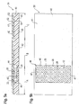
- FIGS. 5a to 7b differ primarily by the number of recesses 44 and their size. So is in the Fig. 5b and 7b only a recess 44 is provided, whereas in Fig. 6b two recesses 44 are formed.
- Fig. 5b is the recess in a first region A of the base body 40, that is arranged in the shoulder zone.
- a second recess 44 in a second region C is provided. Between the first area A and the third area C is the second area B.
- the recess 44 extends almost completely over the base surface of the base body 40, wherein the wall 47 ensures a sufficient lateral support of the spring element unit 20.
- the base body 40 and the cover body 50 as in the Fig. 5a to 7b shown, parallel incisions 60 on.
- the incisions 60 are made in the region of the upper side 52 of the covering body 50 and in the region of the lower side 42 of the base body 40 in the form of a material recess. These cuts 60 reduce the surface tension and thus contribute to an improvement in the point elasticity of the cushioning element 30.
- the incisions 60 in the areas A, B, C at different distances.
- the distance between the incisions 60 in both the base body 40 and in the cover 50 in the region of the recess 44, that is in Fig. 5b in the first area A and in Fig. 6b in the third region C each narrower than in the middle region B of FIGS. 5b and 6b .
- the spacing of the incisions 60 in the region of the spring element units 20 is chosen to be smaller.
- the elasticity in these areas by means of the incisions 60 be set additionally.
- the elasticity can be increased by closer spacing of the incisions 60.
- the incisions 60 are positioned in the region of the single, large-area recess 44 in a plurality of subregions at different distances. In this way, the point elasticity already provided by the large-area spring element unit 20 can be set in detail.
- Fig. 7b and Fig. 5b shown incisions 60 of the in Fig. 6b shown incisions 60 by a widening inwardly cross-sectional shape in the form of a drop.
Landscapes
- Engineering & Computer Science (AREA)
- Aviation & Aerospace Engineering (AREA)
- Transportation (AREA)
- Mechanical Engineering (AREA)
- Mattresses And Other Support Structures For Chairs And Beds (AREA)
- Finger-Pressure Massage (AREA)
Description
- Die vorliegende Erfindung betrifft eine Federelementeinheit gemäß dem Oberbegriff des Anspruchs 1.
- Bei bekannten Federkernmatratzen sind in Stofftaschen eingebrachte Metallfedern als Federelemente vorgesehen. Der so gebildete Metallfederkern wird auch als Bonnellfederkern oder Taschenfederkern bezeichnet. Oberhalb des Metallfederkerns wird eine aus Schaumstoff bestehende Polsterung positioniert, die in der Regel aus Blockschaum gefertigt ist und eine bestimmte Elastizität aufweist. Ferner sind Schaumstoffmatratzen mit in den Schaumstoffkern eingearbeiteten Drahtfedern bekannt.
- Aus der
DE 299 18 893 U1 ist ein Polsterelement für Möbel und Matratzen bekannt, bei dem eine Vielzahl von Federelementen zu einem flächigen Verbund zusammengestellt ist. Hierbei sind die Federelemente aus Schafwolle gefertigt und in vorzugsweise aus Baumwolle hergestellten Taschen eingefüllt, wobei die oberen Stirnseiten der Taschenfedern die spätere Lastfläche bilden. Zur Schaffung eines großflächigen Polsterelementes wird eine Vielzahl der Federelemente nebeneinander angeordnet und in einzelnen Reihen jeweils miteinander verbunden, vorzugsweise miteinander vernäht. -
GB 902 272 A - Ferner ist aus der
DE 39 37 214 A1 ein Polsterelement zur Lagerung eines liegenden menschlichen Körpers bekannt. Ein Matratzenteil aus elastischem Werkstoff, wie beispielsweise Schaumstoff, weist eine Vielzahl nebeneinander angeordneter Kanäle auf, in die Einsatzstücke unterschiedlicher Elastizität eingeschoben sind, so dass das Matratzenteil über seine Liegefläche lokal unterschiedliche Elastizitätsbereiche aufweist. Die Einsatzstücke können aus einem elastischen Werkstoff entsprechend demjenigen des Matratzenteils bestehen. - Bei diesen bekannten Polsterelementen, insbesondere in der Anwendung für Matratzen, hat es sich als nachteilig erwiesen, dass zwischen dem Körper der Person und dem Polsterelement ein Wärme- und Feuchtigkeitsstau entsteht. Diese Problematik tritt bei Matratzen in verstärktem Maße auf, da sich dort die Wärme und Feuchtigkeit infolge der Abdeckung des menschlichen Körpers mit einer Decke, insbesondere im Bereich der Liegefläche der Matratze, ansammelt, die mit dem menschlichen Körper in Kontakt steht.
- Der Erfindung liegt die Aufgabe zugrunde, eine Federelementeinheit und ein Polsterelement vorzuschlagen, die einen Wärme- und Feuchtigkeitsstau zwischen dem Körper und dem Polsterelement verhindern.
- Zur Lösung dieser Aufgabe ist eine Federelementeinheit nach Anspruch 1 vorgesehen.
- Die erfindungsgemäße Federelementeinheit beruht auf der Erkenntnis, das Federelement vollständig aus einem elastischen Polyurethan-Weichschaumstoff zu formen und mit wenigstens einer Ausnehmung zu versehen. Die Ausnehmung dient zum Abtransport von Wärme und Feuchtigkeit beziehungsweise dazu, dass Luft in Richtung der Abstützfläche der Sitz- oder Liegeanordnung strömen kann. Mit anderen Worten bildet die Ausnehmung einen Luftkanal. Grundsätzlich kann das Federelement auch mit mehreren Ausnehmungen versehen werden. Da das Federelement aus einem atmungsaktiven Weichschaumstoff hergestellt ist, wird der Abtransport von Wärme und Feuchtigkeit durch eine Luftströmung zur Abstützfläche hin zusätzlich verbessert.
- Hinzu kommt, dass der Polyurethan-Weichschaumstoff auf einfache Weise mittels Formschäumen in beliebige Formen gebracht werden kann und somit Federelemente unterschiedlichster Formgebung je nach Anwendungsfall und gewünschten Materialkennwerten, wie Elastizität- und Durchlässigkeitswerten, gefertigt werden können. Ferner erweist sich Polyurethan-Weichschaumstoff vorteilhaft in Hinblick auf die Langzeit- beziehungsweise Dauerbelastbarkeit.
- Zudem ist das Federelement frei von Metall, das heißt es erfordert keine metallischen Einlagen beispielsweise in Form von Stahlfedern. Infolgedessen eignet sich die erfindungsgemäße Federelementeinheit insbesondere für Personen, die empfindlich gegen von metallischen Körpern ausgehende magnetische Strahlung sind.
- Die einzelnen Federelemente können mit unterschiedlichen Materialkennwerten, wie insbesondere unterschiedlichen Eindrückhärten, hergestellt werden und so je nach Bedarf zu einem Paket als Federelementeinheit zusammengestellt werden. Bei Bedarf können einzelne Federelemente ausgetauscht werden.
- Die erfindungsgemäße Federelementeinheit kann bei einer Vielzahl von Anwendungen eingesetzt werden. Unter anderem eignet sich die Federelementeinheit für eine Matratze, aber auch für einen Sitz, insbesondere einen Kraftfahrzeug- oder einen Fluggastsitz. Hierbei kann die erfindungsgemäße Federelementeinheit sowohl für die Sitzfläche als auch für die Rückenlehne eingesetzt werden. Weiterhin kann das erfindungsgemäße Federelementeinheit bei Polstermöbeln verwendet werden.
- Vorteilhafte Ausgestaltungen der erfindungsgemäßen Federelementeinheit sind Gegenstand der Ansprüche 2 bis 9.
- Eine vorteilhafte Ausgestaltung besteht darin, dass die Ausnehmung das Federelement vollständig in dessen Axialrichtung durchdringt. So kann das Federelement beispielsweise eine erste Stirnfläche und eine zweite Stirnfläche aufweisen, wobei sich die Ausnehmung dann von der ersten Stirnfläche durchgehend bis zur zweiten Stirnfläche erstreckt. Um einen geeigneten Lüftungskanal zu bilden, verläuft die Ausnehmung vorzugsweise im Wesentlichen senkrecht zur ersten und zweiten Stirnfläche.
- Eine weitere vorteilhafte Ausgestaltung besteht darin, dass das Federelement aus Formschaum gefertigt ist. Hierzu wird bei der Herstellung des Federelements ein Reaktionsgemisch in eine Schäumform eingefüllt und durch Aufschäumen in die endgültige Form gebracht. Um dies erreichen zu können, ist die Schäumform derart ausgebildet, dass das Federelement bereits durch den Schäumvorgang mit der Ausnehmung versehen wird. Auf diese Weise entfällt ein nachträgliches Bohren beziehungsweise Schneiden des Federelements, um die Ausnehmung herzustellen. So lässt sich mittels eines einfachen Schäumverfahrens ein einstückiges Federelement herstellen, das eine geeignete Punktelastizität und eine hohe Atmungsaktivität erreicht. Ferner kann auch eine einstückige Federelementeinheit mit mehreren Federelementen erzeugt werden.
- Vorteilhaft ist die Ausnehmung etwa mittig angeordnet. Auf diese Weise wird ermöglicht, dass sich das Federelement bei der Belastung weitgehend symmetrisch verformt und somit die einzelnen Bereiche des Federelementes weitgehend gleichmäßig beansprucht werden. Ferner kann die Ausnehmung derart positioniert werden, dass ein bestimmtes Verformungsverhalten erreicht wird.
- Hinsichtlich der Formgebung der Ausnehmung erweist es sich als vorteilhaft, wenn die Ausnehmung im Querschnitt und/oder im Längsschnitt eine geradlinige oder kurvenartige Form aufweist. Eine solche Formgebung umfasst auch abschnittsweise geradlinige beziehungsweise kurvenartige und eine kombinierte Form. Auf diese Weise kann auch durch die Formgebung der Ausnehmung das Verformungsverhalten des Federelementes gesteuert beziehungsweise beeinflusst werden. Ferner kann die Form der Ausnehmung entlang ihrer Erstreckungsrichtung innerhalb des Federelementes variabel sein, beispielsweise kegelförmig.
- Auch hinsichtlich der Formgebung des Federelements, das heißt hauptsächlich im Hinblick auf die äußere Mantelfläche des Federelements, können verschiedenartigste Formen gewählt werden. So bietet sich vorrangig eine tonnen- beziehungsweise röhrenartige Form an, das heißt eine Form mit einer eckigen oder runden Grundfläche. Hier kommt beispielsweise eine mindestens dreieckige, insbesondere achteckige, eine kreisrunde oder eine ellipsenförmige Ausgestaltung in Frage. Weiterhin kommt eine über die Höhe der Federelementeinheit veränderliche Querschnittsform in Betracht, wie beispielsweise eine taillierte Form. Auch mittels einer solchen Formgebung der äußeren Mantelfläche des Federelements lässt sich dessen Verformungsverhalten beeinflussen.
- Erfindungsgemäß ist die Federelementeinheit durch eine Vielzahl von nebeneinander angeordneten Federelementen gekennzeichnet, wobei die Federelemente untereinander stoffschlüssig verbunden sind. Auf diese Weise lässt sich eine Federelementeinheit mit beliebiger Anzahl von Federelementen zusammenstellen. Solche unterschiedlichen Federelementpakete können dann zur Bildung einer Abstützfläche miteinander kombiniert werden, wobei die einzelnen Pakete beispielsweise unterschiedliche Elastizitätswerte aufweisen, um den Anforderungen hinsichtlich verschiedener Liege- oder Sitzzonen gerecht werden zu können. Von Vorteil ist ferner, wenn die stoffschlüssige Verbindung wenigstens teilweise elastisch ist. So kann eine zu starre Verbindung der Federelemente verhindert werden.
- Zweckmäßigerweise sind die Federelemente derart nebeneinander angeordnet, dass in einem Bereich zwischen den Aussenflächen benachbarter Federelemente ein Freiraum vorhanden ist. Dieser Freiraum wird vorzugsweise durch eine geeignete Wahl der Form des Federelementes unter Berücksichtigung der verbundartigen Zusammenstellung erreicht. Beispielsweise eignet sich eine achteckige Grundrissform für das Federelement. Der zwischen den Federelementen gebildete Freiraum kann ebenfalls zum Abtransport von Wärme und Feuchtigkeit von der Sitz- beziehungsweise Liegefläche verwendet werden.
- Weiterhin wird zur Lösung der oben genannten Aufgabe in Übereinstimmung mit Anspruch 10 ein Polsterelement, insbesondere eine Matratze, mit einem Grundkörper und einem erfindungsgemäßen Federelementeinheit vorgeschlagen.
- Ein derartiges Polsterelement macht sich die Vorteile der erfindungsgemäßen Federelementeinheit zunutze. Darüber hinaus kann auf ein vergleichsweise aufwendiges Verbinden von mehreren Federelementen in reihenartiger Anordnung mittels Bändern oder auf die Ausbildung von Taschen und deren Einbindung in einen Matratzenkern verzichtet werden. Ferner kann der Grundkörper bevorzugt ebenfalls aus einem Schaumstoffmaterial bestehen, wodurch dann das gesamte Polsterelement metallfrei ist. Zudem lässt sich der Grundkörper auf einfache Weise aus einem Blockschaum herstellen und in beliebiger Abmessung fertigen. Hinsichtlich der Vorteile der vorzugsweise separat hergestellten Federelementeinheit wird auf obige Ausführungen verwiesen.
- Vorteilhafte Ausgestaltungen des erfindungsgemäßen Posterelements sind in den Ansprüchen 11 bis 22 beansprucht.
- Bei einer vorteilhaften Ausgestaltungsform weist der Grundkörper wenigstens eine Aussparung auf, in der die Federelementeinheit aufgenommen ist. Somit können auf der Grundfläche der Aussparung eine Vielzahl von nebeneinander angeordneten Federelementen als eine Federelementeinheit gelagert und beispielsweise durch eine umlaufende Wandung des Grundkörpers seitlich gestützt werden. Vorzugsweise weist die Federelementeinheit etwa die gleiche Höhe wie die Aussparung auf. Die Aussparung kann in Bezug auf die Grundfläche des Grundkörpers beispielsweise in einem solchen Bereich vorgesehen werden, in welchem die Schulterpartie oder das Gesäß einer Person abgestützt wird. Es kann auch nur eine einzige, sich im Wesentlichen über den gesamten Bereich erstreckende Aussparung ausgebildet werden. Von Vorteil ist es insbesondere, bei einer Liege eine Aussparung für den Schulterbereich und eine weitere Aussparung für den Gesäßbereich vorzusehen.
- In einer weiteren bevorzugten Ausgestaltung ist ein Abdeckkörper zur Auflage auf der Federelementeinheit und/oder auf dem Grundkörper vorgesehen, wobei der Abdeckkörper stoffschlüssig mit dem Grundkörper und/oder der Federelementeinheit verbunden, vorzugsweise verklebt, ist. Insbesondere für den Fall, dass in dem Grundkörper eine Ausnehmung vorgesehen ist, bildet der Abdeckkörper quasi einen Deckel und stellt somit einen oberen Abschluss des Polsterelementes dar. Vorteilhafterweise ist der Abdeckkörper aus Polyurethan-Weichschaumstoff hergestellt. Alternativ kann der Abdeckkörper durch eine luftdurchlässige Schicht, insbesondere einen luftdurchlässigen Bezug, gebildet werden.
- Zur Gewährleistung einer dauerhaft festen Positionierung der Federelementeinheit relativ zu dem Grundkörper, ist die Federelementeinheit mit dem Grundkörper stoffschlüssig verbunden, vorzugsweise verklebt. Die Verbindung erfolgt bevorzugt an der Unterseite der Federelementeinheit, das heißt im Bereich jener Fläche, die die Belastung durch den auf dem Polsterelement sitzenden oder liegenden Körper auf den Grundkörper überträgt. Für den Fall, dass die Federelementeinheit in einer Aussparung des Grundkörpers gelagert ist, kann die Federelementeinheit alternativ oder zusätzlich über deren Seitenflächen zumindest abschnittsweise mit der die Ausnehmung begrenzenden Randfläche des Grundkörpers verbunden sein.
- Bei einer weiteren vorteilhaften Ausführungsform ist der Grundkörper gleichermaßen wie das Federelement aus Polyurethan-Weichschaumstoff gefertigt. Vorzugsweise wird der Gründkörper aus Blockschaum hergestellt, so dass ein vollautomatisiertes kontinuierlich durchlaufendes Herstellungsverfahren zur Anwendung kommen kann. Des Weiteren muss nicht eine Vielzahl von Ausgangsstoffen zur Herstellung von Federeinheit und Grundkörper vorgehalten werden.
- Vorteilhafterweise sind der Grundkörper und/oder der Abdeckkörper aus Polyurethan-Weichschaumstoff hergestellt. So kann das gesamte Polsterelement aus einem Basismaterial hergestellt werden.
- Ferner erweist es sich als vorteilhaft, wenn sich die Eindrückhärte der Federelementeinheit von der Eindrückhärte des Grundkörpers und/oder des Abdeckkörpers unterscheidet. Bevorzugt liegt die Eindrückhärte der Federelementeinheit in einem Bereich von etwa 40 N bis etwa 350 N, vorzugsweise in einem Bereich von etwa 60 N bis etwa 260 N.
- Bei einer weiteren vorteilhaften Ausführungsform weist der Grundkörper und/oder der Abdeckkörper zueinander parallele Einschnitte auf. Diese Einschnitte können mit oder ohne Materialentnahme erfolgen. Zudem können die Einschnitte sowohl in Längs- als auch in Querrichtung vorgesehen werden. Mittels der Einschnitte wird die dem Material des Grundkörpers oder Abdeckkörpers eigene Oberflächenspannung reduziert.
- Um Bereiche unterschiedlicher Härte zu erreichen, können die Einschnitte in bestimmten Zonen, wie beispielsweise der Schulterzone oder der Gesäßzone, unterschiedliche Abstände voneinander aufweisen. So lassen näher aneinanderliegende Einschnitte im Bereich der Schulterzone eine größere Weichheit zu, wodurch die Schulter weicher und tiefer einsinken kann, wohingegen Bereiche mit weiter auseinanderliegenden Einschnitten das Federungsverhalten verfestigen und somit mehr Abstützung bieten.
- Von Vorteil ist ferner, wenn die Einschnitte einen sich nach innen erweiternden Querschnitt, insbesondere einen tropfenförmigen Querschnitt, aufweisen. Auf diese Weise wird die Durchlüftung zusätzlich verbessert.
- Vorteilhaft sind der Grundkörper und/oder der Abdeckkörper aus Blockschaum gefertigt, so dass sich Grund- und/oder Abdeckkörper in einem kontinuierlichen Verfahren als Meterware beliebiger Abmessung herstellen lassen. Infolge der in der Regel einfachen geometrischen Abmessungen können Grund- und Abdeckkörper auf einfache Weise zugeschnitten werden. Ferner kann die wenigstens eine Aussparung auf einfache Weise und vollautomatisch durch Ausschneiden geformt werden.
- Vorteilhafterweise ist die Federelementeinheit aus Formschaum gefertigt, wodurch sich ebenfalls ein einfaches Herstellungsverfahren verwirklichen lässt. Zudem kann das durch Formschäumen gefertigte Federelement nach der Entnahme aus dem Schäumwerkzeug auf einfache Weise und vorzugsweise ebenfalls vollautomatisch auf den Grundkörper aufgesetzt beziehungsweise in eine Aussparung des Grundkörpers eingesetzt werden. Dabei erweist sich insbesondere die in dem Federelement vorhandene Ausnehmung als hilfreich.
- Schließlich kann vorgesehen sein, dass der Abdeckkörper einen luftdurchlässigen Bezug umfasst. Ein solcher Bezug kann alternativ oder zusätzlich zu dem oben erwähnten Polyurethan-Weichschaumstoffmaterial vorgesehen sein.
- Nachfolgend wird die Erfindung unter Bezugnahme auf die Zeichnungen weiter erläutert. Dabei zeigen schematisch:
- Fig. 1a
- eine perspektivische Ansicht einer ersten Ausführungsform der erfindungsgemäßen Federelementeinheit;
- Fig. 1 b
- einen Horizontalschnitt durch die Federelementeinheit gemäß
Fig. 1a ; - Fig. 1c
- einen Vertikalschnitt durch die Federelementeinheit gemäß
Fig. 1a ; - Fig. 2
- weitere Ausführungsformen der erfindungsgemäßen Federelementeinheit im Horizontalschnitt alternativ zu
Fig. 1b ; - Fig. 3
- weitere Ausführungsformen der erfindungsgemäßen Federelementeinheit im Vertikalschnitt alternativ zu
Fig. 1c ; - Fig. 4
- einen Horizontalschnitt durch eine erfindungsgemäße Federelementeinheit mit mehreren Federelementen gemäß
Fig. 1a ; - Fig. 5a
- einen Vertikalschnitt durch eine erste Ausführungsform des erfindungsgemäßen Polsterelements mit einer Vielzahl von Federelementeinheiten gemäß
Fig. 4 ; - Fig. 5b
- eine Ansicht von oben auf den Grundkörper des Polsterelementes gemäß
Fig. 5a ohne Abdeckkörper; - Fig. 6a
- einen Vertikalschnitt durch eine zweite Ausführungsform des erfindungsgemäßen Polsterelements mit einer Vielzahl von Federelementeinheiten gemäß
Fig. 4 ; - Fig. 6b
- einen Ansicht von oben auf den Grundkörper des Polsterelementes gemäß
Fig. 6a ohne Abdeckkörper - Fig. 7a
- einen Längsschnitt durch eine dritte Ausführungsform des erfindungsgemäßen Polsterelements mit einer Vielzahl von Federelementeinheiten gemäß
Fig. 4 ; - Fig. 7b
- einen Ansicht von oben auf den Grundkörper des Polsterelementes gemäß
Fig. 7a ohne Abdeckkörper - Die
Fig. 1a bis 1c zeigen ein Federelement 10, aus dem sich die inFig. 4 dargestellte Federelementeinheit 20 aufbaut. Die Federelementeinheit 20 findet Anwendung bei einem Polsterelement 30, beispielsweise in Form einer Matratze, wie in denFiguren 5a bis 7b gezeigt. - Das Federelement 10 besteht ausschließlich aus einem elastischen, offenzelligen Polyurethan-Weichschaumstoff und ist durch Formschäumen hergestellt. Das zylinderförmige Federelement 10 weist eine seitliche Mantelfläche 16, eine Oberseite 14, und eine Unterseite 15 auf. Die Oberseite 14 und die Unterseite 15 sind im Wesentlichen parallel zur Sitz- beziehungsweise Liegefläche ausgerichtet. Wie insbesondere
Fig. 1b zeigt, weist das Federelement 10 einen sich über die gesamte Höhe des Federelementes 10 gleichbleibenden achteckigen Grundriss auf, so dass sich die Mantelfläche 16 in vertikale Anschlussflächen 17 und schräge Seitenflächen 18 unterteilt. - In der Mitte des Federelementes 10 ist eine sich in Axialrichtung erstreckende Ausnehmung 12 vorgesehen, die durch eine entsprechende Ausbildung des Schäumwerkzeuges entsteht. Die Ausnehmung 12 weist einen kreisförmigen Querschnitt (Horizontalschnitt) mit über die Höhe gleich bleibender Form (Vertikalschnitt) auf und dient als Luftkanal zum Abtransport von Wärme und Feuchtigkeit.
- Alternativ dazu kann das Federelement 10 und/oder die Ausnehmung 12 die nur exemplarisch in den
Figuren 2 und 3 angedeuteten Formen aufweisen, wobei auch die einzelnen Mantelflächen und Ausnehmungsformen miteinander kombiniert werden können. Wie inFig. 2 dargestellt, kann das Federelement 10 im Horizontalschnitt betrachtet eine wenigstens abschnittsweise geradlinige oder kurvenartige Form, wie beispielsweise eine kreisförmige, ellipsenförmige oder sechseckige Form aufweisen. Ferner kann das Federelement 10, wie inFig. 3 angedeutet, im Vertikalschnitt betrachtet mit einem über die Höhe veränderlichen Querschnitt versehen sein, wie beispielsweise eine kurvenartige Form, insbesondere eine taillierte Form, oder eine abschnittsweise geradlinige Form, wie beispielsweise eine kegelartige Form und auch Formen, bei denen die Breite beziehungsweise der Durchmesser der Ober- und Unterseite 14, 15 unterschiedlich groß ausgebildet sind. -
Fig. 4 zeigt eine bevorzugte Ausgestaltungsform einer Federelementeinheit 20, die insgesamt vier Federelemente 10 entsprechend denFiguren 1a bis 1c aufweist. Die reihenartig nebeneinander zusammengestellten Federelemente 10 sind im Bereich deren gegenüberliegenden Anschlussflächen 17 mittels einer Klebeverbindung stoffschlüssig miteinander verbunden. Dabei kann die Klebeschicht zumindest teilweise elastisch ausgebildet sein, um eine zu starre Ausbildung der Verbindung zu verhindern. Infolge der achteckigen Grundrissform der Federelemente 10 und der Verbindung über die Anschlussflächen 17 wird zusätzlich zu den einzelnen mittigen Ausnehmungen 12 ein Freiraum 28 im Bereich zwischen den schrägen Seitenflächen 18 geschaffen, der ebenfalls einen Abtransport von Wärme und Feuchtigkeit ermöglicht. - Alternativ zu der in
Fig. 4 gezeigten Federelementeinheit 20 mit vier Federelementen 10 sind auch andere Zusammenstellungen mit einer beliebigen Anzahl von Federelementen 10 denkbar. Auf diese Weise können vorgefertigte Federelementpakete oder Federelementreihen zur Verfügung gestellt werden. - Auf Grundlage der vorstehend erläuterten Federelementeinheit 20 gemäß
Fig. 4 werden im Folgenden mehrere Ausgestaltungsformen eines mit einer Vielzahl von Federelementeinheiten 20 ausgestatteten Polsterelementes 30 erläutert. Dabei unterscheiden sich dieFiguren 5a bis 7b im Wesentlichen durch die Anzahl der vorgesehenen Federelementeinheiten 20 und durch die davon abhängige Ausgestaltung beziehungsweise Anzahl der Aussparungen 44. - So zeigen sämtliche
Figuren 5a bis 7b jeweils ein Polsterelement 30 in Form einer Matratze mit eine den Matratzenkern bildenden Grundkörper 40, einem Abdeckkörper 50 und einer Vielzahl von zwischen Abdeckkörper 50 und Grundkörper 40 angeordneten Federelementeinheiten 20. Sämtliche Bestandteile des Polsterelementes 30, das heißt die einzelnen Federelemente 10 zur Bildung der Federelementeinheit 20, der Grundkörper 40 und der Abdeckkörper 50 bestehen jeweils vollständig aus einem offenzelligen Polyurethan-Weichschaumstoff. Hierbei beträgt die Eindrückhärte der Federelemente 10 etwa 40 N bis etwa 350 N, vorzugsweise etwa 60 N bis etwa 260 N. Der Grundkörper 40 weist eine Oberseite 41, eine Unterseite 42 und eine umlaufende Seitenfläche 43 auf. - Alle in den
Figuren 5a bis 7b dargestellten Aussparungen 44 werden bevorzugt durch Ausschneiden des entsprechenden Materialvolumens aus einem den Grundkörper 40 bildenden Blockschaumkörper hergestellt. Die Aussparung 44 ist jeweils durch eine im Wesentlichen horizontale Grundfläche 45 und eine im Wesentlichen vertikal ausgerichtete umlaufende Randfläche 46 begrenzt. In allen Ausgestaltungsformen gemäß denFiguren 5a bis 7b ist die Federelementeinheit 20 derart durch den Grundkörper 40 gestützt, dass die Federelementeinheit 20 in der Aussparung 44 gelagert ist. Mit anderen Worten liegt die Unterseite 24 der Federelementeinheit 20 auf der Grundfläche 45 auf. Um einen stabilen und dauerhaften Halt der Federelementeinheit 20 in der Aussparung 44 zu gewährleisten, ist die Unterseite 24 mit der Grundfläche 45 mittels einer Klebeschicht stoffschlüssig verbunden. Diese Klebeschicht kann vollflächig, streifenartig oder nur punktuell vorgesehen werden. Zwischen der Seitenfläche 26 der Federelementeinheit 20 und der Randfläche 46 des Grundkörpers 40 kann wenigstens abschnittsweise ein Spalt vorhanden sein. Die zwischen Seitenfläche 43 und Randfläche 46 verbleibende Umrandung 47 weist eine ausreichende Dicke auf, um einen seitlichen Halt der Federelementeinheit 20 sicherzustellen. - Alternativ zu dieser Klebverbindung steht die Seitenfläche 26 der Federelementeinheit 20 mit der Randfläche 46 vollumfänglich in Kontakt. Dieser Kontakt ergibt sich vorzugsweise durch eine Übermaßpassung, das heißt die Abmessungen der Aussparung 44 sind zumindest geringfügig kleiner als die Außenabmessungen der Federelementeinheit 20.
- Nach Einsetzen der Federelementeinheit 20 in die Aussparung 44 und Festlegung vorzugsweise mittels einer Klebeschicht wird der Abdeckkörper 50 auf die Oberseite 41 des Grundkörpers 40 deckungsgleich aufgelegt und mittels einer zumindest stellenweise aufgebrachten Klebeschicht stoffschlüssig mit dem Grundkörper 40 verbunden. Zusätzlich wird die Unterseite des Abdeckkörpers 50 mit der Oberseite 22 der Federelementeinheit 20 verklebt. Der Abdeckkörper 50 weist eine entsprechende Dicke und/oder entsprechende Materialeigenschaften auf, so dass dieser ausreichend luftdurchlässig ist, um einen Wärme- und Feuchtigkeitsabtransport in Richtung zur Federelementeinheit 20 zu gewährleisten. In den Ausführungsbeispielen gemäß den
Fig. 5a bis 7b weist der Abdeckkörper 50 eine Dicke von etwa 40 mm auf. Alternativ kann der Abdeckkörper 50 durch einen luftdurchlässigen Bezug gebildet werden. - Die Ausgestaltungsformen der
Figuren 5a bis 7b unterscheiden sich vorrangig durch die Anzahl der Aussparungen 44 und deren Größe. So ist in denFig. 5b und7b lediglich eine Aussparung 44 vorgesehen, wohingegen inFig. 6b zwei Aussparungen 44 ausgebildet sind. InFig. 5b ist die Aussparung in einem ersten Bereich A des Grundkörpers 40, das heißt in der Schulterzone, angeordnet. InFig. 6b ist zusätzlich eine zweite Aussparung 44 in einem zweiten Bereich C, etwa in der Gesäß-/Hüftzone, vorgesehen. Zwischen erstem Bereich A und drittem Bereich C befindet sich der zweite Bereich B. InFig. 7b erstreckt sich die Aussparung 44 nahezu vollständig über die Grundfläche des Grundkörpers 40, wobei die Wandung 47 einen ausreichenden seitlichen Halt der Federelementeinheit 20 gewährleistet. - Des Weiteren weisen der Grundkörper 40 und der Abdeckkörper 50, wie in den
Fig. 5a bis 7b gezeigt, zueinander parallele Einschnitte 60 auf. Hierbei sind die Einschnitte 60 im Bereich der Oberseite 52 des Abdeckkörpers 50 und im Bereich der Unterseite 42 des Grundkörpers 40 in Form einer Materialausnehmung eingebracht. Diese Einschnitte 60 reduzieren die Oberflächenspannung und tragen somit zu einer Verbesserung der Punktelastizität des Polsterelementes 30 bei. - Wie aus den
Figuren 5a bis 7b ersichtlich, weisen die Einschnitte 60 in den Bereichen A, B, C unterschiedliche Abstände auf. So fällt der Abstand zwischen den Einschnitten 60 sowohl im Grundkörper 40 als auch im Abdeckkörper 50 im Bereich der Aussparung 44, das heißt inFig. 5b im ersten Bereich A und inFig. 6b im dritten Bereich C jeweils enger aus als in dem mittleren Bereich B derFiguren 5b und6b . Mit anderen Worten ist der Abstand der Einschnitte 60 im Bereich der Federelementeinheiten 20 geringer gewählt. So kann die Elastizität in diesen Bereichen mittels der Einschnitte 60 zusätzlich eingestellt werden. Beispielsweise kann die Elastizität durch engere Abstände der Einschnitte 60 erhöht werden. Bei der Variante gemäßFig. 7b sind die Einschnitte 60 darüber hinaus im Bereich der einzigen, großflächigen Aussparung 44 in mehreren Unterbereichen in unterschiedlichen Abständen positioniert. Auf diese Weise lässt sich die bereits durch die großflächige Federelementeinheit 20 bereitgestellte Punktelastizität detailliert einstellen. - Schließlich unterscheiden sich die in
Fig. 7b undFig. 5b dargestellten Einschnitte 60 von den inFig. 6b dargestellten Einschnitten 60 durch eine sich nach innen erweiternde Querschnittsform in Form eines Tropfens.Bezugszeichenliste 10 Federelement 60 Einschnitt 12 Ausnehmung 14 Oberseite A erster Bereich 15 Unterseite B zweiter Bereich 16 Mantelfläche C dritter Bereich 17 Anschlussfläche 18 Seitenfläche 20 Federelementeinheit 22 Oberseite 24 Unterseite 26 Seitenfläche 28 Freiraum 30 Polsterelement 40 Grundkörper 41 Oberseite 42 Unterseite 43 Seitenfläche 44 Aussparung 45 Grundfläche 46 Randfläche 47 Wandung 50 Abdeckkörper 52 Oberseite 54 Unterseite
Claims (21)
- Federelementeinheit (20) mit einer Vielzahl von einzelnen Federelementen (10) für ein Polsterelement (30), insbesondere eine Matratze, wobei das Federelement (10) aus einem offenzelligen Polyurethan-Weichschaumstoff besteht und dass in dem Federelement (10) wenigstens eine Ausnehmung (12) vorgesehen ist und wobei die Vielzahl von Federelementen (10) nebeneinander angeordnet sind, dadurch gekennzeichnet, dass die Federelemente (10) untereinander stoffschlüssig verbunden sind und die stoffschlüssige Verbindung wenigstens teilweise elastisch ist.
- Federelementeinheit (20) nach Anspruch 1, dadurch gekennzeichnet, dass die Ausnehmung (12) das Federelement (10) in dessen Axialrichtung vollständig durchdringt.
- Federelementeinheit (20) nach Anspruch 1 oder 2, dadurch gekennzeichnet, dass das Federelement (10) aus Formschaum gefertigt ist.
- Federelementeinheit (20) nach einem der Ansprüche 1 bis 3, dadurch gekennzeichnet, dass die Ausnehmung (12) etwa mittig angeordnet ist.
- Federelementeinheit (20) nach einem der Ansprüche 1 bis 4, dadurch gekennzeichnet, dass die Ausnehmung (12) im Querschnitt und/oder im Längsschnitt eine geradlinige oder kurvenartige Form aufweist.
- Federelementeinheit (20) nach einem der Ansprüche 1 bis 5, dadurch gekennzeichnet, dass das Federelement (10) im Querschnitt eine achteckige oder kreisförmige Form aufweist.
- Federelementeinheit (20) nach einem der Ansprüche 1 bis 6, dadurch gekennzeichnet, dass die Federelemente (10) untereinander verklebt sind.
- Federelementeinheit (20) nach einem der Ansprüche 1 bis 7, dadurch gekennzeichnet, dass die Federelemente (10) derart nebeneinander angeordnet sind, dass in einem Bereich zwischen den Aussenflächen benachbarter Federelemente (10) ein Freiraum (28) vorhanden ist.
- Polsterelement (30), insbesondere Matratze, mit einem Grundkörper (40) und einer Federelementeinheit (20) nach einem der vorhergehenden Ansprüche.
- Polsterelement (30) nach Anspruch 9, dadurch gekennzeichnet, dass der Grundkörper (40) wenigstens eine Aussparung (44) aufweist, in der die Federelementeinheit (20) aufgenommen ist.
- Polsterelement (30) nach Anspruch 9 oder 10, dadurch gekennzeichnet, dass ein Abdeckkörper (50) zur Auflage auf der Federelementeinheit (20) und/oder auf dem Grundkörper (40) vorgesehen ist, wobei der Abdeckkörper (50) stoffschlüssig mit dem Grundkörper (40) und/oder der Federelementeinheit (20) verbunden, vorzugsweise verklebt, ist.
- Polsterelement (30) nach einem der Ansprüche 9 bis 11, dadurch gekennzeichnet, dass die Federelementeinheit (20) mit dem Grundkörper (40) stoffschlüssig verbunden, vorzugsweise verklebt, ist.
- Polsterelement (30) nach einem der Ansprüche 9 bis 12, dadurch gekennzeichnet, dass der Grundkörper (40) und/oder der Abdeckkörper (50) aus Polyurethan-Weichschaumstoff hergestellt sind.
- Polsterelement (30) nach Anspruch 13, dadurch gekennzeichnet, dass sich die Eindrückhärte der Federelementeinheit (20) von der Eindrückhärte des Grundkörpers (40) und/oder des Abdeckkörpers (50) unterscheidet.
- Polsterelement (30) nach einem der Ansprüche 9 bis 14, dadurch gekennzeichnet, dass die Eindrückhärte der Federelementeinheit (20) in einem Bereich von etwa 40 N bis etwa 350 N, vorzugsweise in einem Bereich von etwa 60 N bis etwa 260 N, liegt.
- Polsterelement (30) nach einem der Ansprüche 9 bis 15, dadurch gekennzeichnet, dass Grundkörper (40) und/oder der Abdeckkörper (50) zueinander parallele Einschnitte (60) aufweist.
- Polsterelement (30) nach Anspruch 16, dadurch gekennzeichnet, dass die Einschnitte (60) unterschiedliche Abstände voneinander aufweisen.
- Polsterelement (30) nach Anspruch 16 oder 17, dadurch gekennzeichnet, dass die Einschnitte (60) einen sich nach innen erweiternden Querschnitt, insbesondere einen tropfenförmigen Querschnitt, aufweisen.
- Polsterelement (30) nach einem der Ansprüche 9 bis 18, dadurch gekennzeichnet, dass der Grundkörper (40) und/oder der Abdeckkörper (50) aus Blockschaum gefertigt sind.
- Polsterelement (30) nach einem der Ansprüche 9 bis 19, dadurch gekennzeichnet, dass die Federelementeinheit (20) aus Formschaum gefertigt ist.
- Polsterelement (30) nach einem der Ansprüche 11 bis 20, dadurch gekennzeichnet, dass der Abdeckkörper (50) einen luftdurchlässigen Bezug umfasst.
Priority Applications (2)
| Application Number | Priority Date | Filing Date | Title |
|---|---|---|---|
| SI200731720T SI2322061T1 (sl) | 2006-05-30 | 2007-05-24 | Enota z vzmetno enoto za oblazinjeni element, zlasti vzmetnico |
| PL10172367T PL2322061T3 (pl) | 2006-05-30 | 2007-05-24 | Zespół elementów sprężynowych dla elementu wyściółkowego, zwłaszcza materaca |
Applications Claiming Priority (3)
| Application Number | Priority Date | Filing Date | Title |
|---|---|---|---|
| DE102006025136A DE102006025136B4 (de) | 2006-05-30 | 2006-05-30 | Polsterelement, insbesondere eine Matratze, und Federelementeinheit für ein solches |
| EP10169303 | 2007-05-24 | ||
| EP07729491A EP1962644B1 (de) | 2006-05-30 | 2007-05-24 | Federelementeinheit für ein polsterelement, insbesondere eine matratze |
Related Parent Applications (4)
| Application Number | Title | Priority Date | Filing Date |
|---|---|---|---|
| EP07729491.6 Division | 2007-05-24 | ||
| EP07729491A Division EP1962644B1 (de) | 2006-05-30 | 2007-05-24 | Federelementeinheit für ein polsterelement, insbesondere eine matratze |
| EP10169303 Division | 2006-05-30 | 2007-05-24 | |
| EP10169303.4 Division | 2010-07-12 |
Publications (2)
| Publication Number | Publication Date |
|---|---|
| EP2322061A1 EP2322061A1 (de) | 2011-05-18 |
| EP2322061B1 true EP2322061B1 (de) | 2015-09-30 |
Family
ID=38650304
Family Applications (2)
| Application Number | Title | Priority Date | Filing Date |
|---|---|---|---|
| EP07729491A Not-in-force EP1962644B1 (de) | 2006-05-30 | 2007-05-24 | Federelementeinheit für ein polsterelement, insbesondere eine matratze |
| EP10172367.4A Active EP2322061B1 (de) | 2006-05-30 | 2007-05-24 | Federelementeinheit für ein Polsterelement, insbesondere eine Matratze |
Family Applications Before (1)
| Application Number | Title | Priority Date | Filing Date |
|---|---|---|---|
| EP07729491A Not-in-force EP1962644B1 (de) | 2006-05-30 | 2007-05-24 | Federelementeinheit für ein polsterelement, insbesondere eine matratze |
Country Status (10)
| Country | Link |
|---|---|
| US (2) | US7865989B2 (de) |
| EP (2) | EP1962644B1 (de) |
| AT (1) | ATE473658T1 (de) |
| DE (4) | DE102006025136B4 (de) |
| DK (1) | DK2322061T3 (de) |
| ES (2) | ES2555216T3 (de) |
| PL (2) | PL2322061T3 (de) |
| PT (1) | PT2322061E (de) |
| SI (1) | SI2322061T1 (de) |
| WO (1) | WO2007137993A2 (de) |
Families Citing this family (57)
| Publication number | Priority date | Publication date | Assignee | Title |
|---|---|---|---|---|
| DE102006025136B4 (de) | 2006-05-30 | 2008-07-10 | Metzeler Schaum Gmbh | Polsterelement, insbesondere eine Matratze, und Federelementeinheit für ein solches |
| WO2008048743A2 (en) * | 2006-08-29 | 2008-04-24 | Ascion Llc | A foam spring mattress configured with variable firmness |
| USD600541S1 (en) | 2008-07-22 | 2009-09-22 | Metzeler Schaum Gmbh | Tube |
| PT104190B (pt) * | 2008-09-26 | 2009-07-17 | Soundsleep Ind E Com De Colcho | Colchão com circulação de ar dotado de núcleo constituído por elementos elásticos e processo de desmoldagem deste |
| DE102008061801A1 (de) | 2008-12-11 | 2010-07-08 | Metzeler Schaum Gmbh | Verfahren zur Herstellung eines Flächengebildes, insbesondere einer Polsterelementauflage, ein solches Flächengebilde und ein Polsterelement |
| DE102008055549B4 (de) | 2008-12-18 | 2014-07-24 | Ct Formpolster Gmbh | Federelement aus Schaumstoff |
| CN101822467A (zh) * | 2009-03-04 | 2010-09-08 | 际诺思(厦门)轻工制品有限公司 | 海绵床垫结构 |
| AU2009350434B2 (en) * | 2009-07-29 | 2014-11-27 | Technogel Italia S.R.L. | Modular support element |
| DE102009044308A1 (de) | 2009-10-21 | 2011-04-28 | Ct Formpolster Gmbh | Klimatisiertes Polsterelement |
| DE202009016130U1 (de) | 2009-11-26 | 2010-04-08 | Fränkische Schlafmanufaktur Zagefka GmbH | Metallfreies Schaumstofffederelement für Matratzen, Polsterungen von Sitzmöbeln, Auflagen für Wasserbetten |
| DE202010001402U1 (de) | 2010-01-27 | 2010-04-01 | Breckle Gmbh Matratzenfabrik | Geschäumter Matratzenkörper |
| DE102010014664B4 (de) | 2010-04-12 | 2015-02-12 | Metzeler Schaum Gmbh | Polsterelement, insbesondere eine Matratze |
| EP2384671B1 (de) * | 2010-05-04 | 2013-11-06 | Yos Soetanto Theosabrata | Bettgestellanordnung |
| DE202010017045U1 (de) | 2010-12-24 | 2011-03-31 | Breckle Gmbh Matratzenfabrik | Geschäumter Matratzenkörper |
| US8776798B2 (en) | 2011-07-22 | 2014-07-15 | Prs Medical Technologies, Inc. | Method and devices for prevention and treatment of pressure ulcers |
| US10485691B2 (en) | 2011-07-22 | 2019-11-26 | Prs Medical Technologies, Inc. | Independently adjustable support system |
| US8656919B2 (en) * | 2011-07-22 | 2014-02-25 | Prs Medical Technologies, Inc. | System for prevention and treatment of pressure ulcers |
| US9339407B2 (en) | 2011-07-22 | 2016-05-17 | Prs Medical Technologies, Inc. | Apparatus and methods for conforming a support to a body |
| US9326905B2 (en) | 2011-07-22 | 2016-05-03 | Prs Medical Technologies, Inc. | Apparatus and methods for adjusting a support to a body |
| US8790765B2 (en) * | 2011-12-19 | 2014-07-29 | Fomosa Sounding Corp. | Pad structure for absorbing vibration and dispersing pressure |
| USD683993S1 (en) | 2012-03-30 | 2013-06-11 | James R. Malkiewicz | Unitary foam bed resiliency element |
| USD724863S1 (en) | 2012-07-20 | 2015-03-24 | Carpenter Co. | Cushion |
| US9211017B2 (en) * | 2012-08-01 | 2015-12-15 | Sealy Technology, Llc | Air flow mattress constructions and variable density mattress cores |
| JP2016501672A (ja) * | 2012-12-28 | 2016-01-21 | テンピュール−ペディック・マネジメント・リミテッド・ライアビリティ・カンパニー | 移動性増強マットレス |
| WO2014113737A1 (en) | 2013-01-19 | 2014-07-24 | Wolfson Martin | No-glue pocketed spring unit construction |
| DE102013004414B4 (de) | 2013-03-15 | 2017-08-03 | Hans Ulrich Schwenk | Mehrschichtiges Polster mit zonierter und belüftender Mittelschicht und Verfahren zu seiner Herstellung |
| US20150013066A1 (en) * | 2013-06-07 | 2015-01-15 | Balanced Path, LLC | Yoga Mat |
| CN103689948A (zh) * | 2013-11-29 | 2014-04-02 | 杭州长命乳胶海绵有限公司 | 乳胶压簧床垫柱 |
| EP2898797A1 (de) | 2014-01-24 | 2015-07-29 | Tobia Esquete, Fernando | Matratze mit verbesserter Wärme- und Feuchtigkeitsableitung |
| DE202014003262U1 (de) | 2014-04-16 | 2014-05-21 | Breckle Gmbh Matratzenfabrik | Geschäumter Matratzenkörper |
| US9706851B2 (en) * | 2014-07-30 | 2017-07-18 | James Malkiewicz | Mattress core |
| DE102014110988A1 (de) * | 2014-08-01 | 2016-02-04 | Maiers Bettwarenfabrik GmbH + Co. KG | Matratze |
| JP6379964B2 (ja) * | 2014-10-09 | 2018-08-29 | アイシン精機株式会社 | マットレス |
| JP2016087340A (ja) * | 2014-11-11 | 2016-05-23 | フランスベッド株式会社 | 枕及びクッション構造体 |
| BE1022700A9 (nl) * | 2015-02-03 | 2017-03-17 | Advanced Spring Tech Naamloze Vennootschap | Cilindrisch schuimlichaam, gebruik daarvan en werkwijze om dit te vervaardigen |
| USD860067S1 (en) * | 2016-03-30 | 2019-09-17 | Roger Thomas Mascull | Set of contouring units |
| CA3000143C (en) * | 2015-09-30 | 2020-06-02 | MASCULL, Elizabeth Jocelyn | Contouring system and components |
| USD969036S1 (en) * | 2015-09-30 | 2022-11-08 | Roger Thomas Mascull | Set of contouring units |
| US10849438B1 (en) * | 2015-11-03 | 2020-12-01 | Underpucks LLC | Modular mattress renewal system |
| US10327564B1 (en) * | 2015-11-03 | 2019-06-25 | Underpucks LLC | Modular mattress renewal system |
| US20170325596A1 (en) * | 2016-05-13 | 2017-11-16 | Perfect Pressure Inc. | Foam mattress having an adjustable mattress core for adjusting and customizing its firmness, assembling method and kit thereof |
| US20170340131A1 (en) * | 2016-05-24 | 2017-11-30 | Healthcare Co., Ltd | Foam filling elements |
| WO2017207538A1 (de) | 2016-06-01 | 2017-12-07 | Covestro Deutschland Ag | Visko-elastischer dämpfungskörper und verfahren zu seiner herstellung |
| USD850986S1 (en) * | 2016-09-16 | 2019-06-11 | Roger Thomas Mascull | Set of contouring units for postural support |
| KR102615170B1 (ko) * | 2016-11-03 | 2023-12-18 | 코웨이 주식회사 | 경도 조절이 가능한 매트리스 어셈블리 |
| US20190254439A1 (en) | 2016-11-04 | 2019-08-22 | Covestro Deutschland Ag | Visco-elastic damping element based on visco-elastic materials |
| WO2018213203A1 (en) * | 2017-05-15 | 2018-11-22 | Dyob, Llc | Modular mattress systems and methods |
| JP2021509074A (ja) | 2017-11-22 | 2021-03-18 | エリサナ エス・アー・エール・エル | 中空管状中央膨張発泡体ばね |
| US11622635B2 (en) * | 2019-07-26 | 2023-04-11 | Dreamwell, Ltd. | Mattress assembly |
| GB2589839B (en) * | 2019-11-12 | 2021-12-08 | Shock Wbv Ltd | Shock mitigation seat |
| TWI786818B (zh) * | 2021-09-10 | 2022-12-11 | 葛復中 | 氣動式獨立筒及其應用 |
| US12213595B2 (en) * | 2021-09-24 | 2025-02-04 | Inconceivable Ventures, Inc. | Cushioning and support system |
| US20230098525A1 (en) * | 2021-09-24 | 2023-03-30 | Inconceivable Ventures, Inc. | Cushioning and support system |
| US11950704B2 (en) * | 2021-10-26 | 2024-04-09 | Dreamwell, Ltd. | Bedding components including a convoluted foam layer |
| DE102022101143A1 (de) | 2022-01-19 | 2023-07-20 | Bayerische Motoren Werke Aktiengesellschaft | Sitzvorrichtung für ein Fahrzeug |
| US12082706B2 (en) * | 2022-08-08 | 2024-09-10 | T Tiet HANH | Waist support chair |
| US20250268388A1 (en) * | 2024-02-23 | 2025-08-28 | Blue Bell Mattress Company, Llc | Mattresses with comfort and stability zones |
Citations (1)
| Publication number | Priority date | Publication date | Assignee | Title |
|---|---|---|---|---|
| DE19521910C1 (de) * | 1995-05-06 | 1996-09-26 | Huelsta Werke Huels Kg | Polsterelement aus Schaumstoff |
Family Cites Families (39)
| Publication number | Priority date | Publication date | Assignee | Title |
|---|---|---|---|---|
| BE411250A (de) | ||||
| CA321473A (en) | 1932-04-12 | Restonair | Air ventilated cushion | |
| US1296359A (en) | 1915-03-01 | 1919-03-04 | Daniel Webster Brown | Pneumatic mat. |
| FR709641A (fr) | 1930-09-11 | 1931-08-11 | Matelas, coussins et analogues perméables à l'air | |
| GB368909A (en) | 1931-01-19 | 1932-03-17 | Max Sherover | Improvements in and relating to mattresses |
| GB376291A (en) | 1931-04-02 | 1932-07-04 | Francis Henry Carter | Improvements in resilient surfaces for beds, seats, cushions and upholstery |
| US1980445A (en) | 1932-04-27 | 1934-11-13 | Sherover Max | Mattress |
| FR794573A (fr) | 1934-09-14 | 1936-02-20 | App Orthopediques Unic | Dispositif élastique pour coussins, sièges, matelas et articles similaires |
| GB476659A (en) * | 1935-03-07 | 1937-12-13 | Us Rubber Prod Inc | Improvements in cushions |
| US2530058A (en) | 1946-11-08 | 1950-11-14 | Aladdin Ind Ltd | Radiator for space heating |
| US2539058A (en) | 1947-09-16 | 1951-01-23 | Stephen J Burns | Cushion construction |
| US2887425A (en) | 1954-03-26 | 1959-05-19 | Hexcel Products Inc | Method of making rubber honeycomb product |
| US3047282A (en) | 1956-04-26 | 1962-07-31 | Mobay Chemical Corp | Upholstery units |
| GB902272A (en) | 1959-07-17 | 1962-08-01 | Dunlop Rubber Co | Improved cushions or pillows of foamed plastic material |
| GB936540A (en) | 1961-08-10 | 1963-09-11 | Slumberland Group Ltd | Improvements in seats |
| CA913815A (en) | 1969-05-30 | 1972-10-31 | Convexco Limited | Spring upholstery assembly |
| US3720966A (en) | 1970-04-22 | 1973-03-20 | M Zysman | Spring upholstery cushioning |
| US3885257A (en) | 1972-10-30 | 1975-05-27 | Evans Ronald J P | Pressure controlled resilient supporting structure |
| US4042987A (en) | 1976-04-16 | 1977-08-23 | Ronald J. P. Evans | Resilient support |
| BE859468A (nl) * | 1977-10-07 | 1978-04-07 | Poppe Willy | Schuimveer |
| DE7829649U1 (de) * | 1977-10-07 | 1979-02-15 | Poppe, Willy, Sint-Niklaas (Belgien) | Schaumfederkoerper |
| DE3937214A1 (de) | 1989-11-08 | 1991-05-16 | Walter Prof Dr Kuehnegger | Orthese zur lagerung des liegenden menschlichen koerpers |
| DE4029947A1 (de) | 1990-07-11 | 1992-01-16 | Werner Lueck | Matratze |
| DE4300414A1 (de) | 1992-12-08 | 1994-06-09 | Lueck Werner | Posterelementaufbau |
| US5353455A (en) * | 1993-05-12 | 1994-10-11 | Carpenter Co. | Padding body with individual modular elements |
| WO1995022922A1 (en) | 1994-02-23 | 1995-08-31 | Franz Hoet | Cushion, mattress or analogous element and resilient elements for use therein |
| JP3616410B2 (ja) * | 1994-10-03 | 2005-02-02 | 株式会社ジェイエスピー | クッション材 |
| DE29918893U1 (de) | 1999-10-27 | 2000-01-13 | Binder, Rudolf, 90409 Nürnberg | Textil-Federelement für Polstermöbel und Matratzen |
| KR100391512B1 (ko) * | 2000-05-12 | 2003-07-22 | 최연수 | 탄성체 구조물, 이의 제조 방법 및 이를 포함하는 매트리스 |
| US6347423B1 (en) * | 2000-09-29 | 2002-02-19 | Sidhil Technology, Llc | Jacketed cushioning elements and assemblies thereof in mattresses and upholstery |
| JP2004041513A (ja) * | 2002-07-12 | 2004-02-12 | France Bed Co Ltd | マットレス及びこのマットレスを用いたベッド装置 |
| DE10327258A1 (de) * | 2003-06-17 | 2005-01-20 | Klaus Prof. Dr. Heckmann | Polster, insbesondere Anti-Dekubitus-Matratze |
| ES2234410B1 (es) * | 2003-07-31 | 2006-06-01 | Philopatent, S.A. | Colchon de muelles de espuma. |
| BRPI0614035A2 (pt) * | 2005-06-17 | 2011-03-09 | Nomaco Inc | elementos de suporte de carga/amortecimento/suporte e método de fabricação |
| CN100506117C (zh) * | 2005-06-20 | 2009-07-01 | 廖秀真 | 组合式床垫 |
| DE102006025136B4 (de) * | 2006-05-30 | 2008-07-10 | Metzeler Schaum Gmbh | Polsterelement, insbesondere eine Matratze, und Federelementeinheit für ein solches |
| WO2008048743A2 (en) * | 2006-08-29 | 2008-04-24 | Ascion Llc | A foam spring mattress configured with variable firmness |
| ITMI20070173U1 (it) * | 2007-05-09 | 2008-11-10 | New Wind S R L | Materasso con molleggio registrabile |
| US7571504B2 (en) * | 2007-11-21 | 2009-08-11 | Chun Fu Kuo | Cushioning device having changeable cushioning members |
-
2006
- 2006-05-30 DE DE102006025136A patent/DE102006025136B4/de not_active Withdrawn - After Issue
-
2007
- 2007-05-24 ES ES10172367.4T patent/ES2555216T3/es active Active
- 2007-05-24 PL PL10172367T patent/PL2322061T3/pl unknown
- 2007-05-24 US US12/161,822 patent/US7865989B2/en active Active
- 2007-05-24 DE DE202007009374U patent/DE202007009374U1/de not_active Expired - Lifetime
- 2007-05-24 PT PT101723674T patent/PT2322061E/pt unknown
- 2007-05-24 DE DE202007018463U patent/DE202007018463U1/de not_active Expired - Lifetime
- 2007-05-24 PL PL07729491T patent/PL1962644T3/pl unknown
- 2007-05-24 DE DE502007004385T patent/DE502007004385D1/de active Active
- 2007-05-24 EP EP07729491A patent/EP1962644B1/de not_active Not-in-force
- 2007-05-24 AT AT07729491T patent/ATE473658T1/de active
- 2007-05-24 WO PCT/EP2007/055062 patent/WO2007137993A2/de not_active Ceased
- 2007-05-24 DK DK10172367.4T patent/DK2322061T3/en active
- 2007-05-24 SI SI200731720T patent/SI2322061T1/sl unknown
- 2007-05-24 EP EP10172367.4A patent/EP2322061B1/de active Active
- 2007-05-24 ES ES07729491T patent/ES2345685T3/es active Active
-
2010
- 2010-12-29 US US12/980,742 patent/US8099812B2/en not_active Expired - Fee Related
Patent Citations (1)
| Publication number | Priority date | Publication date | Assignee | Title |
|---|---|---|---|---|
| DE19521910C1 (de) * | 1995-05-06 | 1996-09-26 | Huelsta Werke Huels Kg | Polsterelement aus Schaumstoff |
Also Published As
| Publication number | Publication date |
|---|---|
| US20100218318A1 (en) | 2010-09-02 |
| DE102006025136A1 (de) | 2007-12-06 |
| ATE473658T1 (de) | 2010-07-15 |
| EP1962644B1 (de) | 2010-07-14 |
| DE202007018463U1 (de) | 2008-08-07 |
| EP1962644A2 (de) | 2008-09-03 |
| ES2555216T3 (es) | 2015-12-29 |
| DE102006025136B4 (de) | 2008-07-10 |
| PL2322061T3 (pl) | 2016-03-31 |
| US7865989B2 (en) | 2011-01-11 |
| DE502007004385D1 (de) | 2010-08-26 |
| DK2322061T3 (en) | 2016-01-11 |
| DE202007009374U1 (de) | 2007-09-20 |
| ES2345685T3 (es) | 2010-09-29 |
| EP2322061A1 (de) | 2011-05-18 |
| US8099812B2 (en) | 2012-01-24 |
| WO2007137993A2 (de) | 2007-12-06 |
| PT2322061E (pt) | 2015-12-30 |
| WO2007137993A3 (de) | 2008-04-10 |
| PL1962644T3 (pl) | 2010-12-31 |
| US20110126356A1 (en) | 2011-06-02 |
| SI2322061T1 (sl) | 2016-02-29 |
Similar Documents
| Publication | Publication Date | Title |
|---|---|---|
| EP1962644B1 (de) | Federelementeinheit für ein polsterelement, insbesondere eine matratze | |
| EP3083327B1 (de) | Schaumteil, insbesondere für einen fahrzeugsitz und fahrzeugsitz | |
| EP1068094B1 (de) | Sitzpolster für Fahrzeugsitze | |
| EP2941366B1 (de) | Schaumteil, insbesondere für einen fahrzeugsitz, sowie verfahren und werkzeug zur herstellung eines schaumteils | |
| DE19801172B4 (de) | Sitz, insbesondere Fahrzeugsitz | |
| DE102008055549B4 (de) | Federelement aus Schaumstoff | |
| DE102007051232C5 (de) | Matratze | |
| EP2449925A1 (de) | Matratze und Verfahren zur ihrer Herstellung | |
| DE102010014664B4 (de) | Polsterelement, insbesondere eine Matratze | |
| DE202012002092U1 (de) | Mehrlagige Matratze, insbesondere für Säuglinge und/oder Kleinkinder | |
| EP3578087B1 (de) | Matratze mit einem zweilagigen matratzenkern und einsinkzonen für hüft- und schulterbereich | |
| DE3725146A1 (de) | Sitz, insbesondere fuer kraftfahrzeuge | |
| EP1808100B1 (de) | Kopf- oder Körperunterlage, Kissen oder dergleichen | |
| EP1629815B1 (de) | Matratze | |
| LU103195B1 (de) | Liege- und/oder Sitzunterlage aus einem dauerelastischen Material | |
| DE3939320C2 (de) | Stuhl, insbesondere zahnärztlicher Behandlungsstuhl | |
| DE102004046517A1 (de) | Polsterelement aus Schaumstoff | |
| EP3348172B1 (de) | Modulare matratze | |
| DE102011122011B4 (de) | Fahrzeugsitz mit Polsterteil mit Nahtbereich | |
| DE102006037080B4 (de) | Polsterschicht | |
| EP0657126A1 (de) | Füllkörper aus elastischem Material und Verfahren zu dessen Herstellung | |
| DE20111116U1 (de) | Sitzpolster | |
| DE202025107119U1 (de) | Matratze mit Randbereich | |
| DE20202355U1 (de) | Liegematte, insbesondere Matratze oder selbst aufblasendes Polster | |
| DE102011121993A1 (de) | Fahrzeugsitz, Verfahren zum Herstellen eines Fahrzeugsitzposterteils und Verwendung eines Heißpressstempels |
Legal Events
| Date | Code | Title | Description |
|---|---|---|---|
| PUAI | Public reference made under article 153(3) epc to a published international application that has entered the european phase |
Free format text: ORIGINAL CODE: 0009012 |
|
| AC | Divisional application: reference to earlier application |
Ref document number: 1962644 Country of ref document: EP Kind code of ref document: P |
|
| AK | Designated contracting states |
Kind code of ref document: A1 Designated state(s): AT BE BG CH CY CZ DE DK EE ES FI FR GB GR HU IE IS IT LI LT LU LV MC MT NL PL PT RO SE SI SK TR |
|
| 17P | Request for examination filed |
Effective date: 20111111 |
|
| REG | Reference to a national code |
Ref country code: DE Ref legal event code: R079 Ref document number: 502007014281 Country of ref document: DE Free format text: PREVIOUS MAIN CLASS: A47C0027140000 Ipc: A47C0027150000 |
|
| GRAP | Despatch of communication of intention to grant a patent |
Free format text: ORIGINAL CODE: EPIDOSNIGR1 |
|
| GRAS | Grant fee paid |
Free format text: ORIGINAL CODE: EPIDOSNIGR3 |
|
| RIC1 | Information provided on ipc code assigned before grant |
Ipc: B60N 2/70 20060101ALI20150715BHEP Ipc: A47C 27/20 20060101ALI20150715BHEP Ipc: A47C 27/15 20060101AFI20150715BHEP Ipc: A47C 27/14 20060101ALI20150715BHEP |
|
| INTG | Intention to grant announced |
Effective date: 20150728 |
|
| GRAA | (expected) grant |
Free format text: ORIGINAL CODE: 0009210 |
|
| AC | Divisional application: reference to earlier application |
Ref document number: 1962644 Country of ref document: EP Kind code of ref document: P |
|
| AK | Designated contracting states |
Kind code of ref document: B1 Designated state(s): AT BE BG CH CY CZ DE DK EE ES FI FR GB GR HU IE IS IT LI LT LU LV MC MT NL PL PT RO SE SI SK TR |
|
| REG | Reference to a national code |
Ref country code: CH Ref legal event code: EP Ref country code: GB Ref legal event code: FG4D Free format text: NOT ENGLISH |
|
| REG | Reference to a national code |
Ref country code: AT Ref legal event code: REF Ref document number: 751866 Country of ref document: AT Kind code of ref document: T Effective date: 20151015 |
|
| REG | Reference to a national code |
Ref country code: IE Ref legal event code: FG4D Free format text: LANGUAGE OF EP DOCUMENT: GERMAN |
|
| REG | Reference to a national code |
Ref country code: DE Ref legal event code: R096 Ref document number: 502007014281 Country of ref document: DE |
|
| REG | Reference to a national code |
Ref country code: ES Ref legal event code: FG2A Ref document number: 2555216 Country of ref document: ES Kind code of ref document: T3 Effective date: 20151229 |
|
| REG | Reference to a national code |
Ref country code: PT Ref legal event code: SC4A Free format text: AVAILABILITY OF NATIONAL TRANSLATION Effective date: 20151202 |
|
| REG | Reference to a national code |
Ref country code: CH Ref legal event code: NV Representative=s name: BOHEST AG, CH |
|
| REG | Reference to a national code |
Ref country code: DK Ref legal event code: T3 Effective date: 20160107 |
|
| REG | Reference to a national code |
Ref country code: SE Ref legal event code: TRGR |
|
| PG25 | Lapsed in a contracting state [announced via postgrant information from national office to epo] |
Ref country code: LV Free format text: LAPSE BECAUSE OF FAILURE TO SUBMIT A TRANSLATION OF THE DESCRIPTION OR TO PAY THE FEE WITHIN THE PRESCRIBED TIME-LIMIT Effective date: 20150930 |
|
| REG | Reference to a national code |
Ref country code: NL Ref legal event code: FP |
|
| PG25 | Lapsed in a contracting state [announced via postgrant information from national office to epo] |
Ref country code: IS Free format text: LAPSE BECAUSE OF FAILURE TO SUBMIT A TRANSLATION OF THE DESCRIPTION OR TO PAY THE FEE WITHIN THE PRESCRIBED TIME-LIMIT Effective date: 20160130 Ref country code: EE Free format text: LAPSE BECAUSE OF FAILURE TO SUBMIT A TRANSLATION OF THE DESCRIPTION OR TO PAY THE FEE WITHIN THE PRESCRIBED TIME-LIMIT Effective date: 20150930 |
|
| REG | Reference to a national code |
Ref country code: FR Ref legal event code: PLFP Year of fee payment: 10 |
|
| REG | Reference to a national code |
Ref country code: SK Ref legal event code: T3 Ref document number: E 20074 Country of ref document: SK |
|
| REG | Reference to a national code |
Ref country code: GR Ref legal event code: EP Ref document number: 20150402740 Country of ref document: GR Effective date: 20160414 |
|
| REG | Reference to a national code |
Ref country code: DE Ref legal event code: R097 Ref document number: 502007014281 Country of ref document: DE |
|
| PLBE | No opposition filed within time limit |
Free format text: ORIGINAL CODE: 0009261 |
|
| STAA | Information on the status of an ep patent application or granted ep patent |
Free format text: STATUS: NO OPPOSITION FILED WITHIN TIME LIMIT |
|
| 26N | No opposition filed |
Effective date: 20160701 |
|
| REG | Reference to a national code |
Ref country code: IE Ref legal event code: MM4A |
|
| REG | Reference to a national code |
Ref country code: FR Ref legal event code: PLFP Year of fee payment: 11 |
|
| PG25 | Lapsed in a contracting state [announced via postgrant information from national office to epo] |
Ref country code: IE Free format text: LAPSE BECAUSE OF NON-PAYMENT OF DUE FEES Effective date: 20160524 |
|
| REG | Reference to a national code |
Ref country code: FR Ref legal event code: PLFP Year of fee payment: 12 |
|
| PG25 | Lapsed in a contracting state [announced via postgrant information from national office to epo] |
Ref country code: HU Free format text: LAPSE BECAUSE OF FAILURE TO SUBMIT A TRANSLATION OF THE DESCRIPTION OR TO PAY THE FEE WITHIN THE PRESCRIBED TIME-LIMIT; INVALID AB INITIO Effective date: 20070524 Ref country code: RO Free format text: LAPSE BECAUSE OF FAILURE TO SUBMIT A TRANSLATION OF THE DESCRIPTION OR TO PAY THE FEE WITHIN THE PRESCRIBED TIME-LIMIT Effective date: 20150930 Ref country code: CY Free format text: LAPSE BECAUSE OF FAILURE TO SUBMIT A TRANSLATION OF THE DESCRIPTION OR TO PAY THE FEE WITHIN THE PRESCRIBED TIME-LIMIT Effective date: 20150930 |
|
| PG25 | Lapsed in a contracting state [announced via postgrant information from national office to epo] |
Ref country code: MC Free format text: LAPSE BECAUSE OF FAILURE TO SUBMIT A TRANSLATION OF THE DESCRIPTION OR TO PAY THE FEE WITHIN THE PRESCRIBED TIME-LIMIT Effective date: 20150930 Ref country code: MT Free format text: LAPSE BECAUSE OF FAILURE TO SUBMIT A TRANSLATION OF THE DESCRIPTION OR TO PAY THE FEE WITHIN THE PRESCRIBED TIME-LIMIT Effective date: 20150930 |
|
| PG25 | Lapsed in a contracting state [announced via postgrant information from national office to epo] |
Ref country code: BG Free format text: LAPSE BECAUSE OF FAILURE TO SUBMIT A TRANSLATION OF THE DESCRIPTION OR TO PAY THE FEE WITHIN THE PRESCRIBED TIME-LIMIT Effective date: 20150930 |
|
| PGFP | Annual fee paid to national office [announced via postgrant information from national office to epo] |
Ref country code: LU Payment date: 20190521 Year of fee payment: 13 Ref country code: NL Payment date: 20190521 Year of fee payment: 13 |
|
| PGFP | Annual fee paid to national office [announced via postgrant information from national office to epo] |
Ref country code: ES Payment date: 20190619 Year of fee payment: 13 Ref country code: FI Payment date: 20190517 Year of fee payment: 13 Ref country code: PL Payment date: 20190516 Year of fee payment: 13 Ref country code: DK Payment date: 20190523 Year of fee payment: 13 Ref country code: IT Payment date: 20190521 Year of fee payment: 13 Ref country code: LT Payment date: 20190515 Year of fee payment: 13 Ref country code: CZ Payment date: 20190517 Year of fee payment: 13 |
|
| PGFP | Annual fee paid to national office [announced via postgrant information from national office to epo] |
Ref country code: SE Payment date: 20190523 Year of fee payment: 13 Ref country code: BE Payment date: 20190521 Year of fee payment: 13 Ref country code: FR Payment date: 20190521 Year of fee payment: 13 Ref country code: GR Payment date: 20190521 Year of fee payment: 13 Ref country code: SI Payment date: 20190516 Year of fee payment: 13 Ref country code: TR Payment date: 20190514 Year of fee payment: 13 |
|
| PGFP | Annual fee paid to national office [announced via postgrant information from national office to epo] |
Ref country code: SK Payment date: 20190513 Year of fee payment: 13 Ref country code: CH Payment date: 20190523 Year of fee payment: 13 |
|
| PGFP | Annual fee paid to national office [announced via postgrant information from national office to epo] |
Ref country code: AT Payment date: 20190517 Year of fee payment: 13 Ref country code: GB Payment date: 20190523 Year of fee payment: 13 |
|
| REG | Reference to a national code |
Ref country code: FI Ref legal event code: MAE |
|
| REG | Reference to a national code |
Ref country code: DK Ref legal event code: EBP Effective date: 20200531 |
|
| REG | Reference to a national code |
Ref country code: NL Ref legal event code: MM Effective date: 20200601 |
|
| REG | Reference to a national code |
Ref country code: LT Ref legal event code: MM4D Effective date: 20200524 |
|
| REG | Reference to a national code |
Ref country code: AT Ref legal event code: MM01 Ref document number: 751866 Country of ref document: AT Kind code of ref document: T Effective date: 20200524 |
|
| REG | Reference to a national code |
Ref country code: SK Ref legal event code: MM4A Ref document number: E 20074 Country of ref document: SK Effective date: 20200524 |
|
| PG25 | Lapsed in a contracting state [announced via postgrant information from national office to epo] |
Ref country code: CZ Free format text: LAPSE BECAUSE OF NON-PAYMENT OF DUE FEES Effective date: 20200524 Ref country code: LT Free format text: LAPSE BECAUSE OF NON-PAYMENT OF DUE FEES Effective date: 20200524 Ref country code: FI Free format text: LAPSE BECAUSE OF NON-PAYMENT OF DUE FEES Effective date: 20200524 Ref country code: LI Free format text: LAPSE BECAUSE OF NON-PAYMENT OF DUE FEES Effective date: 20200531 Ref country code: AT Free format text: LAPSE BECAUSE OF NON-PAYMENT OF DUE FEES Effective date: 20200524 Ref country code: SE Free format text: LAPSE BECAUSE OF NON-PAYMENT OF DUE FEES Effective date: 20200525 Ref country code: CH Free format text: LAPSE BECAUSE OF NON-PAYMENT OF DUE FEES Effective date: 20200531 Ref country code: GR Free format text: LAPSE BECAUSE OF NON-PAYMENT OF DUE FEES Effective date: 20201209 Ref country code: PT Free format text: LAPSE BECAUSE OF NON-PAYMENT OF DUE FEES Effective date: 20201124 |
|
| PG25 | Lapsed in a contracting state [announced via postgrant information from national office to epo] |
Ref country code: SK Free format text: LAPSE BECAUSE OF NON-PAYMENT OF DUE FEES Effective date: 20200524 Ref country code: NL Free format text: LAPSE BECAUSE OF NON-PAYMENT OF DUE FEES Effective date: 20200601 |
|
| REG | Reference to a national code |
Ref country code: BE Ref legal event code: MM Effective date: 20200531 |
|
| GBPC | Gb: european patent ceased through non-payment of renewal fee |
Effective date: 20200524 |
|
| PG25 | Lapsed in a contracting state [announced via postgrant information from national office to epo] |
Ref country code: LU Free format text: LAPSE BECAUSE OF NON-PAYMENT OF DUE FEES Effective date: 20200524 |
|
| REG | Reference to a national code |
Ref country code: DE Ref legal event code: R082 Ref document number: 502007014281 Country of ref document: DE Representative=s name: BECKER KURIG & PARTNER PATENTANWAELTE MBB, DE Ref country code: DE Ref legal event code: R082 Ref document number: 502007014281 Country of ref document: DE Ref country code: DE Ref legal event code: R082 Ref document number: 502007014281 Country of ref document: DE Representative=s name: BECKER & KURIG PARTNERSCHAFT PATENTANWAELTE MB, DE |
|
| PG25 | Lapsed in a contracting state [announced via postgrant information from national office to epo] |
Ref country code: GB Free format text: LAPSE BECAUSE OF NON-PAYMENT OF DUE FEES Effective date: 20200524 Ref country code: FR Free format text: LAPSE BECAUSE OF NON-PAYMENT OF DUE FEES Effective date: 20200531 Ref country code: DK Free format text: LAPSE BECAUSE OF NON-PAYMENT OF DUE FEES Effective date: 20200531 |
|
| REG | Reference to a national code |
Ref country code: SI Ref legal event code: KO00 Effective date: 20210317 |
|
| REG | Reference to a national code |
Ref country code: DE Ref legal event code: R082 Ref document number: 502007014281 Country of ref document: DE Representative=s name: BECKER KURIG & PARTNER PATENTANWAELTE MBB, DE Ref country code: DE Ref legal event code: R082 Ref document number: 502007014281 Country of ref document: DE Representative=s name: BECKER & KURIG PARTNERSCHAFT PATENTANWAELTE MB, DE |
|
| PG25 | Lapsed in a contracting state [announced via postgrant information from national office to epo] |
Ref country code: BE Free format text: LAPSE BECAUSE OF NON-PAYMENT OF DUE FEES Effective date: 20200531 Ref country code: SI Free format text: LAPSE BECAUSE OF NON-PAYMENT OF DUE FEES Effective date: 20200525 |
|
| PG25 | Lapsed in a contracting state [announced via postgrant information from national office to epo] |
Ref country code: IT Free format text: LAPSE BECAUSE OF NON-PAYMENT OF DUE FEES Effective date: 20200524 |
|
| PG25 | Lapsed in a contracting state [announced via postgrant information from national office to epo] |
Ref country code: ES Free format text: LAPSE BECAUSE OF NON-PAYMENT OF DUE FEES Effective date: 20200525 |
|
| PG25 | Lapsed in a contracting state [announced via postgrant information from national office to epo] |
Ref country code: TR Free format text: LAPSE BECAUSE OF NON-PAYMENT OF DUE FEES Effective date: 20200524 |
|
| PG25 | Lapsed in a contracting state [announced via postgrant information from national office to epo] |
Ref country code: PL Free format text: LAPSE BECAUSE OF NON-PAYMENT OF DUE FEES Effective date: 20200524 |
|
| P01 | Opt-out of the competence of the unified patent court (upc) registered |
Effective date: 20230517 |
|
| PGFP | Annual fee paid to national office [announced via postgrant information from national office to epo] |
Ref country code: DE Payment date: 20250519 Year of fee payment: 19 |