EP2321058B1 - Zentrifuge mit einem kupplungselement zur axialen verriegelung eines rotors - Google Patents
Zentrifuge mit einem kupplungselement zur axialen verriegelung eines rotors Download PDFInfo
- Publication number
- EP2321058B1 EP2321058B1 EP09778316.1A EP09778316A EP2321058B1 EP 2321058 B1 EP2321058 B1 EP 2321058B1 EP 09778316 A EP09778316 A EP 09778316A EP 2321058 B1 EP2321058 B1 EP 2321058B1
- Authority
- EP
- European Patent Office
- Prior art keywords
- rotor
- drive head
- centrifuge
- coupling element
- coupling
- Prior art date
- Legal status (The legal status is an assumption and is not a legal conclusion. Google has not performed a legal analysis and makes no representation as to the accuracy of the status listed.)
- Active
Links
- 230000008878 coupling Effects 0.000 title claims description 68
- 238000010168 coupling process Methods 0.000 title claims description 68
- 238000005859 coupling reaction Methods 0.000 title claims description 68
- 238000006073 displacement reaction Methods 0.000 claims description 8
- 230000000284 resting effect Effects 0.000 claims 1
- 238000011109 contamination Methods 0.000 description 6
- 230000006835 compression Effects 0.000 description 4
- 238000007906 compression Methods 0.000 description 4
- 238000010276 construction Methods 0.000 description 3
- 230000001419 dependent effect Effects 0.000 description 3
- 230000000694 effects Effects 0.000 description 3
- 238000004519 manufacturing process Methods 0.000 description 3
- 241000209035 Ilex Species 0.000 description 2
- 229910000831 Steel Inorganic materials 0.000 description 2
- 239000000463 material Substances 0.000 description 2
- 239000010959 steel Substances 0.000 description 2
- 239000004809 Teflon Substances 0.000 description 1
- 229920006362 Teflon® Polymers 0.000 description 1
- 239000000853 adhesive Substances 0.000 description 1
- 230000001070 adhesive effect Effects 0.000 description 1
- 238000005119 centrifugation Methods 0.000 description 1
- 238000006243 chemical reaction Methods 0.000 description 1
- 239000011248 coating agent Substances 0.000 description 1
- 238000000576 coating method Methods 0.000 description 1
- 230000007423 decrease Effects 0.000 description 1
- 238000011161 development Methods 0.000 description 1
- 230000018109 developmental process Effects 0.000 description 1
- 238000010586 diagram Methods 0.000 description 1
- 238000003780 insertion Methods 0.000 description 1
- 230000037431 insertion Effects 0.000 description 1
- 230000035945 sensitivity Effects 0.000 description 1
- 239000007787 solid Substances 0.000 description 1
- 230000003068 static effect Effects 0.000 description 1
Images

Classifications
-
- B—PERFORMING OPERATIONS; TRANSPORTING
- B04—CENTRIFUGAL APPARATUS OR MACHINES FOR CARRYING-OUT PHYSICAL OR CHEMICAL PROCESSES
- B04B—CENTRIFUGES
- B04B9/00—Drives specially designed for centrifuges; Arrangement or disposition of transmission gearing; Suspending or balancing rotary bowls
- B04B9/08—Arrangement or disposition of transmission gearing ; Couplings; Brakes
-
- B—PERFORMING OPERATIONS; TRANSPORTING
- B04—CENTRIFUGAL APPARATUS OR MACHINES FOR CARRYING-OUT PHYSICAL OR CHEMICAL PROCESSES
- B04B—CENTRIFUGES
- B04B7/00—Elements of centrifuges
- B04B7/02—Casings; Lids
- B04B2007/025—Lids for laboratory centrifuge rotors
-
- B—PERFORMING OPERATIONS; TRANSPORTING
- B04—CENTRIFUGAL APPARATUS OR MACHINES FOR CARRYING-OUT PHYSICAL OR CHEMICAL PROCESSES
- B04B—CENTRIFUGES
- B04B9/00—Drives specially designed for centrifuges; Arrangement or disposition of transmission gearing; Suspending or balancing rotary bowls
- B04B9/08—Arrangement or disposition of transmission gearing ; Couplings; Brakes
- B04B2009/085—Locking means between drive shaft and rotor
Definitions
- the invention relates to a centrifuge with a drive head which is connectable to a drive, a rotor which can be detachably mounted on the drive head, at least one connecting element, with which the drive head is rotatably connected to the rotor, and at least one coupling element which on the drive head is mounted and can exert an axial force on the rotor so that the rotor can be axially fixed, wherein the axial force increases with increasing rotational speed of the drive head.
- a centrifuge may receive sample containers and be used to separate components of the samples contained therein at a high rotational speed of a centrifuge rotor.
- a centrifuge rotor In a floor-standing centrifuge, which has a height that reaches up to a worktable, there is a relatively large amount of space for the device components.
- a bench centrifuge placed on a worktable a low overall height is desired so that the available space inside the centrifuge must be well utilized. This causes, for example, the top of a centrifuge rotor to be relatively close to the lid of the centrifuge.
- the rotor top usually has a large planar surface which rotates only a few millimeters below the centrifuge lid, whereas the rotor bottom has a rugged geometry in which a Bernoulli attraction is produced only to a lesser extent.
- the aerodynamic influence can be supplemented by a dynamic influence, for example due to an external impulse of the centrifuge. In such an impact, it may happen that the elastically mounted engine tilts to the side and axial forces are generated, which overlap with the buoyancy of the rotor.
- the centrifuge according to the invention has a drive head which can be connected to a drive, a rotor which can be detachably mounted on the drive head, at least one connecting element with which the drive head can be connected in a rotationally fixed manner to the rotor, and at least one coupling element which is attached to the drive head is and can exert an axial force on the rotor so that the rotor can be axially fixed, and with increasing rotational speed of the drive head due to the centrifugal force and the axially directed force increases, the coupling element transmits to the rotor, the axial force by means of a ramp surface, which is inclined at an angle to the horizontal in a range of greater than 0 ° to 15 °.
- the coupling element can cause self-locking by means of such inclined ramp surface, so that the rotor can not unlock the coupling element at a standstill, low or high speed. At standstill, such an effect is particularly advantageous because the user can convince himself by an attempted removal of the rotor from the drive head, whether the rotor is locked securely. At high speed, the locking force increases due to the ramp surface, as the axial force component increases with increasing centrifugal force.
- the coupling element is pivotable about a pivot axis between an unlocking position, in which it is pivoted into the drive head, whereby the rotor is unlocked relative to the drive head, and between a locking position, in which the coupling element with the ramp surface of a lateral surface of the Actuator protrudes and transmits an axial force to the rotor, whereby the rotor is locked with respect to the drive head.
- the coupling element can swing completely into the drive head, the ramp surface can not act on any surface of the rotor, whereby the rotor can be moved in the axial direction. This allows it to be removed from the drive axle.
- the pivoting of the coupling element can be easily induced without special tools.
- the coupling element there are only two positions for the coupling element, one position being an unlocking position for the removal or insertion of the rotor, and the other position being a locking position for the safe holding of the rotor even with buoyant forces arising. If the coupling element is resiliently biased so that it assumes the locking position when the rotor is at rest, there is high certainty that the rotor is always locked, unless the coupling elements are displaced against the spring force in the unlocked position.
- the connecting element is arranged in the pivot axis of the coupling element, with which the drive head is rotatably connected to the rotor.
- the coupling element may have a coupling tooth, which can cooperate with an actuating element such that a pivoting movement can be exerted on the coupling element, so that a displacement of the coupling element from the locking position to the unlocking position or vice versa is feasible.
- the coupling tooth may be a cam or a projection and is preferably formed integrally with the coupling element.
- the contact surface of the coupling tooth with the actuating element may have a hardened surface, so that the wear of the coupling tooth is low with frequent displacement in the unlocking position.
- the actuator In a resiliently biased coupling element, the actuator must overcome only the spring force and possibly an adhesive force of the coupling element with the rotor.
- the centrifuge can be designed so that the actuating element can be arranged in the axis of rotation of the centrifuge and is conical at one end, so that upon axial displacement of the actuating element, the conical end can interact with the projection of the coupling element.
- the actuator must thus be moved only vertically, so that the wedge-shaped end comes into contact with the clutch tooth and this can pivot to the side. The displacement of the coupling elements from the locking position to the unlocking position can thus be carried out very easily and without tools.
- the axial force exerted by the coupling element acts on a sleeve which is fixedly mounted on the rotor.
- a sleeve which is fixedly mounted on the rotor.
- wear can occur at the contact surfaces of the rotor, so that the entire rotor would have to be replaced.
- a sleeve is used between the rotor and the drive head, it can be easily replaced with a wear of the sleeve, wherein the rotor is used unchanged.
- the sleeve can also be easily mounted on the rotor by means of a screw or the like. The wear can be reduced by a Teflon coating of the sleeve.
- the drive head has a lateral surface which has a cylindrical surface and a frusto-conical surface, wherein the lateral surface rests positively on a corresponding holding surface of the rotor or the sleeve when the rotor or the sleeve is mounted with the drive head, wherein the cylindrical surface has a length , which is at least a quarter of the length of the holding surface.
- the cylindrical surface serves to guide the rotor or the sleeve, wherein the frustoconical surface serves as a stop surface in the axial direction when placing the rotor on the drive head.
- the cylinder surface can be made very precisely with little manufacturing effort, so that an accurate guide can be achieved.
- the truncated cone surface has a cone angle of 15 ° to 40 ° to the axis of rotation, contamination on the frustoconical surface will only have a minor effect. Contamination or buildup on the frusto-conical surface causes the rotor or sleeve to seat earlier than a clean frusto-conical surface. The larger the truncated cone angle, the lower the height offset, so that the coupling elements can still be reliably pivoted into the locking position.
- the cylindrical surface or frustoconical surface of the drive head has at least one recess, in particular a transverse recess. This can be swept down the vertical surface of the rotor or the sleeve, any existing dirt on the cylindrical surface of the drive head down and collect in this recess in the area of the cylinder surface or truncated cone surface. Thus, despite contamination can achieve a precise position of the rotor.
- the cylindrical surface of the drive head to the holding surface of the rotor or the sleeve is designed as a clearance, which ensures a secure guidance of the rotor at a standstill and at high rotational speed.
- a clearance fit can be made relatively easily and inexpensively.
- a cross-sectional view of a centrifuge 100 according to the invention is shown without substructure.
- the centrifuge 100 has a rotor 1, which has a multiplicity of recesses 2 for receiving sample containers with material to be centrifuged.
- a sleeve 3 is mounted, which rests positively on a drive head 4.
- two vertically extending connecting elements 5 are mounted in the form of pins, which engage positively in each case in a recess 6 in the rotor 1.
- two connecting elements 5 are shown, which are arranged symmetrically to the axis of rotation 7, wherein more than two connecting elements 5 may be provided.
- these connecting elements 5 transmit a torque to the rotor 1, so that it can be set in rotation.
- the symmetrical arrangement of the connecting elements 5 ensures that the torque is transmitted uniformly to the rotor 1.
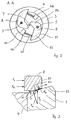
- the centrifuge 100 has two coupling elements 8 each arranged symmetrically with respect to the axis of rotation 7, see also Fig. 2 which is a view along the section line AA in Fig. 1 shows.
- the coupling elements 8 are arranged on the drive head 4 and can pivot to the side.
- the pivot axis 9 is formed in each case by the connecting element 5.
- the rotor 1 If the rotor 1 is to be connected to the drive head 4, the rotor 1 is moved from top to bottom in the direction of the drive head 4.
- the sleeve 3 mounted on the rotor 1, with its frustoconical surface 32 strikes a respective outer edge 81 of the coupling elements 8, which are in each case pushed away from a stop 46 by a compression spring 45.
- the coupling elements 8 By lowering the sleeve 3 with its frustoconical surface 32 on the respective edges 81, the coupling elements 8 are pivoted so that the respective outer edge 81 comes into coincidence with the surface line 44 of the drive head 4.
- the elongated portion 82 of each coupling element 8 is thereby pivoted in the direction of the axis of rotation 7 against the spring force of the compression spring 45.
- the sleeve 3 or the rotor 1 can slide on further lowering in the vertical direction past the coupling elements 8 until the frustoconical surface 32 rests on a corresponding frustoconical surface 42 of the drive head 4.
- the frustoconical surface 42 serves as a stop and limits the downward movement of the rotor 1.
- the coupling elements 8 due to the spring force of the compression spring 45, automatically swing back to its previous position, see Fig. 1 and 2 ,
- the elongated portion 82 of each coupling element 8 protrudes beyond the generatrix 44 of the drive head 4, wherein each coupling element 8 contacts the sleeve 3.
- the coupling elements form a quick coupling, whereby the rotor can be connected quickly and without tools to the drive head. If an operator wants to check whether the rotor 1 is seated on the drive head 4, he can try to pull the rotor 1 upwards. Since the rotor 1 and the sleeve 3 rests against coupling elements 8, a vertical displacement upwards is not possible. The operator recognizes that the rotor is firmly connected to the drive head 4.
- the coupling elements 8 can be released from the sleeve 3 when an actuator 10 is moved vertically downwards along the axis of rotation 7, see Fig. 1 .
- the actuating element 10, which is connected in this embodiment with a resiliently biased pushbutton 11, has a cone-shaped end, which on a coupling tooth 84 of the coupling element 8, see Fig. 2 , can attack.
- the cone-shaped end exerts a force perpendicular to the axis of rotation 7, so that the coupling element 8 can be pivoted so until the outer edge 81 again comes into coincidence with the surface line 44 or even further into the drive head is displaced. Then the rotor 1 can be pulled up again and released from the drive head 4.
- Fig. 3 is shown in a detailed view of the contact of the coupling element 8 with the sleeve 3.
- the coupling element 8 has a ramp surface 83 which is inclined at an angle ⁇ to the horizontal.
- the ramp surface 83 positively contacts the corresponding ramp surface 33 of the sleeve 3, which is also inclined at an angle ⁇ to the horizontal.
- the coupling element 8 and the sleeve 3 form due to the ramp surfaces 33, 83 each have a wedge body. Acts on the rotor 1 and the sleeve 3 due to a high number of revolutions, a buoyancy force F A , are in cooperation with a coupling element 8 on the pair of surfaces 33, 83 in Fig. 3 shown reaction forces.
- the holding force F H is opposed by a restoring force F R of the coupling element 8.
- the buoyancy force F A the coupling element 8 is not for
- Fig. 5 a detail in the area of contact between the drive head 4 and sleeve 3 is shown.
- the drive head 4 has in the region of the truncated cone a dirt deposit 48 of thickness t. If the sleeve 3 or the rotor 1 is lowered, the frustoconical surface 32 of the sleeve no longer reaches the frustoconical surface 42 of the drive head 4, but remains at a height which is higher by the amount h than if no contamination were present.
- the sensitivity to such a dirt deposit is the lower, the larger the truncated cone angle ⁇ , since thus the height difference between a clean and a dirty cone to be bridged by the coupling elements becomes smaller. Since the available space for the movement of the coupling elements 8 is limited and you can assume a contamination of a maximum of 0.5 mm, in this embodiment, the truncated cone angle is about 35 °.
- the influence of contamination on the cylinder surface 41 can be kept low if recesses 47 are provided in the region of the frustoconical surface 42 of the drive head. They absorb a dirt layer present in the area of the cylindrical surface 41 when lowering the sleeve 3 and prevent it from additionally accumulating on the frustoconical surface 42.
Description
- Die Erfindung betrifft eine Zentrifuge mit einem Antriebskopf, der mit einem Antrieb verbindbar ist, einem Rotor, der sich am Antriebskopf lösbar montieren lässt, mindestens einem Verbindungselement, mit dem der Antriebskopf mit dem Rotor drehfest verbindbar ist, und mindestens einem Kupplungselement, welches am Antriebskopf angebracht ist und eine axiale Kraft auf den Rotor so ausüben kann, dass sich der Rotor axial fixieren lässt, wobei die axiale Kraft bei ansteigender Drehgeschwindigkeit des Antriebskopfes zunimmt.
- Eine Zentrifuge kann Probenbehältnisse aufnehmen und dazu verwendet werden, Bestandteile der darin enthaltenen Proben bei hoher Drehgeschwindigkeit eines Zentrifugenrotors voneinander zu trennen. Bei einer Standzentrifuge, die auf einem Fußboden angeordnet ist und eine Höhe besitzt, die bis zu einem Arbeitstisch reicht, besteht für die Gerätekomponenten relativ viel Platz. Bei einer Tischzentrifuge hingegen, die auf einem Arbeitstisch angeordnet ist, ist eine geringe Bauhöhe erwünscht, so dass der verfügbare Raum innerhalb der Zentrifuge gut genutzt werden muss. Dies bewirkt, dass sich zum Beispiel die Oberseite eines Zentrifugenrotors relativ nahe an dem Deckel der Zentrifuge befindet. Ist dieser Abstand kleiner als der Abstand der Rotorunterseite zum Kesselboden der Zentrifuge, wird die Rotoroberseite stärker zum Deckel hingezogen, als die Rotorunterseite zum Kesselboden hingezogen wird. Dies lässt sich mit dem Gesetz von Bernoulli erklären. Allgemein hat dieser Umstand zur Folge, dass auf den Zentrifugenrotor in der Summe eine nach oben gerichtete Kraft wirkt. Bei einer Drehzahl von etwa 6000 Umdrehungen pro Minute kann bei einer üblichen Zentrifuge eine Auftriebskraft in Höhe von 100 N erzeugt werden. Dies wird noch dadurch begünstigt, dass die Rotoroberseite meist eine große plane Oberfläche aufweist, die nur wenige Millimeter unterhalb des Zentrifugendeckels rotiert, wohingegen die Rotorunterseite eine zerklüftete Geometrie besitzt, bei der eine Anziehungskraft gemäß Bernoulli nur in geringerem Maße erzeugt wird.
- Der aerodynamische Einfluss kann noch durch einen dynamischen Einfluss zum Beispiel aufgrund eines äußeren Anstoßes der Zentrifuge ergänzt werden. Bei einem derartigen Anstoß kann es vorkommen, dass der elastisch gelagerte Motor sich zur Seite neigt und axiale Kräfte erzeugt werden, welche sich mit der Auftriebskraft des Rotors überlagern.
- Um die aerodynamischen und dynamischen Einflüsse beherrschen zu können, werden bei Zentrifugen im Stand der Technik starre Verriegelungen eingesetzt. Diese verhindern zuverlässig eine axiale Verlagerung des Rotors bei hohen Drehzahlen. Die Verriegelungen benötigen jedoch spezielles Werkzeug, um sie sicher anbringen und wieder lösen zu können, so dass die Montagearbeiten vor und nach einem Zentrifugierlauf relativ viel Zeit in Anspruch nehmen. Zudem gibt es Verriegelungen, die drehzahlabhängig wirken, so dass im Stillstand oder bei niedriger Drehzahl der Rotor vom Antriebskopf gegen eine geringe Kraft abgezogen werden kann. Eine solche Verriegelung funktioniert nur dann zuverlässig, wenn die Auftriebskräfte gerade immer kleiner sind als die Verriegelungskräfte. Eine derartige Konstruktion ist nicht für alle Rotor/Zentrifugenkombinationen geeignet und durch die schwierige Bestimmbarkeit der Auftriebskräfte durch dynamische Einflüsse auch schwer berechenbar. Eine weitere Zentrifuge zum Stand der Technik beschreibt die
US 6 063 018 A , welche den Oberbegriff des Anspruchs 1 offenbart. - Es besteht somit eine Aufgabe darin, eine Zentrifuge zu schaffen, welche bei Stillstand, bei niedrigen und bei hohen Drehzahlen eine zuverlässige Verriegelung gegen axiale Auftriebskräfte, die gegen den Zentrifugenrotor wirken, sicherstellt, wobei bei ansteigender Drehgeschwindigkeit des Zentrifugenrotors die Verriegelungskraft in axialer Richtung noch zunimmt. Ferner soll mit wenig Zeitaufwand und ohne spezielles Werkzeug der Rotor mit dem Antriebskopf montiert oder demontiert werden können.
- Die Aufgabe wird durch eine Zentrifuge gemäß dem Gegenstand des unabhängigen Patentanspruches gelöst. Vorteilhafte Weiterbildungen der Erfindung sind Gegenstand der Unteransprüche.
- Die erfindungsgemäße Zentrifuge weist einen Antriebskopf, der mit einem Antrieb verbindbar ist, einen Rotor, der sich am Antriebskopf lösbar montieren lässt, mindestens ein Verbindungselement, mit dem der Antriebskopf mit dem Rotor drehfest verbindbar ist, und mindestens ein Kupplungselement auf, welches am Antriebskopf angebracht ist und eine axiale Kraft auf den Rotor so ausüben kann, dass sich der Rotor axial fixieren lässt, wobei bei ansteigender Drehgeschwindigkeit des Antriebskopfes aufgrund der Zentrifugalkraft auch die axial gerichtete Kraft zunimmt, wobei das Kupplungselement auf den Rotor die axiale Kraft mittels einer Rampenfläche überträgt, welche in einem Winkel zur Horizontalen in einem Bereich von größer 0° bis 15° geneigt ist.
- Das Kupplungselement kann mittels einer derart geneigten Rampenfläche eine Selbsthemmung bewirken, so dass der Rotor bei Stillstand, niedriger oder hoher Drehzahl das Kupplungselement nicht entriegeln kann. Im Stillstand ist eine solche Wirkung besonders vorteilhaft, da sich der Anwender durch ein versuchtes Abziehen des Rotors vom Antriebskopf davon überzeugen kann, ob der Rotor auch sicher verriegelt ist. Bei hoher Drehzahl erhöht sich die Verriegelungskraft aufgrund der Rampenfläche, da bei zunehmender Zentrifugalkraft auch die axiale Kraftkomponente zunimmt.
- Es ist vorteilhaft, wenn das Kupplungselement um eine Schwenkachse schwenkbar ist zwischen einer Entriegelungsposition, in der es in den Antriebskopf eingeschwenkt ist, wodurch der Rotor bezüglich des Antriebskopfes entriegelt ist, und zwischen einer Verriegelungsposition, in der das Kupplungselement mit der Rampenfläche von einer Mantelfläche des Antriebskopfes vorsteht und auf den Rotor eine axiale Kraft überträgt, wodurch der Rotor bezüglich des Antriebskopfes verriegelt ist. Indem das Kupplungselement vollständig in den Antriebskopf einschwenken kann, kann die Rampenfläche auf keine Fläche des Rotors einwirken, wodurch sich der Rotor in axiale Richtung bewegen lässt. Damit kann er von der Antriebsachse entfernt werden. Das Schwenken des Kupplungselementes kann einfach und ohne spezielles Werkzeug induziert werden. Für das Kupplungselement gibt es somit nur zwei Positionen, wobei die eine Position eine Entriegelungsposition für das Entfernen oder Einsetzen des Rotors ist, und die andere Position eine Verriegelungsposition für das sichere Halten des Rotors auch bei entstehenden Auftriebskräften ist. Wenn das Kupplungselement federnd so vorgespannt ist, dass es bei Stillstand des Rotors die Verriegelungsposition einnimmt, besteht eine hohe Sicherheit, dass der Rotor immer verriegelt ist, falls nicht die Kupplungselemente gegen die Federkraft in die Entriegelungsposition verlagert werden.
- In einer weiteren Ausführungsform der Erfindung ist in der Schwenkachse des Kupplungselementes das Verbindungselement angeordnet, mit dem der Antriebskopf mit dem Rotor drehfest verbindbar ist. Eine solche Konstruktion ist vorteilhaft, da das Verbindungselement die Funktion der Schwenkachse einnehmen kann, so dass nur ein Bauteil benötigt wird. Damit ist eine platzsparende und leichte Konstruktion realisierbar.
- Das Kupplungselement kann einen Kupplungszahn aufweisen, welcher mit einem Betätigungselement derart zusammenwirken kann, dass sich auf das Kupplungselement eine Schwenkbewegung ausüben lässt, so dass eine Verlagerung des Kupplungselementes von der Verriegelungsposition in die Entriegelungsposition oder umgekehrt durchführbar ist. Der Kupplungszahn kann eine Nocke oder ein Vorsprung sein und ist vorzugsweise mit dem Kupplungselement einstückig ausgebildet. Die Kontaktfläche des Kupplungszahns mit dem Betätigungselement kann eine gehärtete Oberfläche aufweisen, so dass der Verschleiß des Kupplungszahnes bei häufigem Verlagern in die Entriegelungsposition gering ist. Bei einem federnd vorgespannten Kupplungselement muss das Betätigungselement nur die Federkraft und eventuell eine Haftkraft des Kupplungselementes mit dem Rotor überwinden.
- Die Zentrifuge kann so ausgebildet sein, dass sich das Betätigungselement in der Drehachse der Zentrifuge anordnen lässt und an einem Ende kegelförmig ausgebildet ist, so dass bei axialer Verlagerung des Betätigungselementes das kegelförmige Ende mit dem Überstand des Kupplungselementes wechselwirken kann. Das Betätigungselement muss damit nur vertikal bewegt werden, so dass das keilförmige Ende in Kontakt mit dem Kupplungszahn kommt und dieses zur Seite schwenken kann. Das Verlagern der Kupplungselemente von der Verriegelungsposition in die Entriegelungsposition lässt sich somit sehr einfach und ohne Werkzeug durchführen.
- Bei einer weiteren Ausführungsform der Erfindung wirkt die vom Kupplungselement ausgeübte axiale Kraft auf eine Hülse, welche am Rotor fest montiert ist. Bei häufigem Aufsetzen des Rotors auf den Antriebskopf kann an den Berührflächen des Rotors ein Verschleiß auftreten, so dass der gesamte Rotor ausgewechselt werden müsste. Indem zwischen Rotor und Antriebskopf eine Hülse eingesetzt wird, kann bei einem Verschleiß der Hülse diese einfach ausgetauscht werden, wobei der Rotor unverändert verwendbar ist. Die Hülse läst sich zudem einfach am Rotor mittels eines Schraubverbindung oder ähnlichem montieren. Der Verschleiß kann durch eine Teflonbeschichtung der Hülse vermindert werden.
- Gemäß der Erfindung besitzt der Antriebskopf eine Mantelfläche, welche eine Zylinderfläche und eine Kegelstumpffläche aufweist, wobei die Mantelfläche an einer korrespondierenden Haltefläche des Rotors oder der Hülse formschlüssig anliegt, wenn der Rotor oder die Hülse mit dem Antriebskopf montiert ist, wobei die Zylinderfläche eine Länge aufweist, welche mindestens ein Viertel der Länge der Haltefläche ist. Bei dieser Ausführungsform dient die Zylinderfläche zur Führung des Rotors oder der Hülse, wobei die Kegelstumpffläche als Anschlagsfläche in axialer Richtung beim Aufsetzen des Rotors auf den Antriebskopf dient. Die Zylinderfläche kann mit wenig Fertigungsaufwand sehr genau gefertigt werden, so dass eine genaue Führung erzielbar ist. Bei einer Führung durch den Kegelstumpf ist hingegen ein hoher Aufwand bei der Fertigung erforderlich, wobei eine genaue Führung nur schwer erreicht werden kann. Form-, Lage- und Maßtoleranzen wirken sich bei einer Kegelstumpfführung ganz unterschiedlich auf die Zentrizität des Rotors aus und sind auch schwierig messbar. Ein gleichmäßiges Tragbild eines Kegelstumpfes kann meistens nur durch Schleifen erreicht werden. Durch den Verzicht auf eine Führung durch den Kegelstumpf und ausschließliche Nutzung der Zylinderfläche als Führungsfläche lässt sich der Fertigungs- und Kontrollaufwand verringern. Die Führungsgenauigkeit erhöht sich mit zunehmender Länge der Zylinderfläche.
- Weist die Kegelstumpffläche einen Kegelwinkel von 15° bis 40° zur Drehachse auf, wirken sich Verschmutzungen auf der Kegelstumpffläche nur geringfügig aus. Eine Verschmutzung oder ein Belag auf der Kegelstumpffläche führt dazu, dass der Rotor oder die Hülse früher aufsitzt als bei einer sauberen Kegelstumpffläche. Je größer der Kegelstumpfwinkel ist, umso geringer ist der Höhenversatz, so dass sich die Kupplungselemente noch zuverlässig in die Verriegelungsposition schwenken lassen.
- Besonders vorteilhaft ist es, wenn die Zylinderfläche oder Kegelstumpffläche des Antriebskopfes mindestens eine Ausnehmung, insbesondere einen Quer-Einstich, aufweist. Damit kann beim vertikalen Absenken des Rotors oder der Hülse ein eventuell vorhandener Schmutzauftrag auf der Zylinderfläche des Antriebskopfes nach unten abgestrichen werden und sich in dieser Ausnehmung im Bereich der Zylinderfläche oder Kegelstumpffläche sammeln. Somit lässt sich trotz Verschmutzung eine genaue Position des Rotors erreichen.
- In einer weiteren Ausführungsform der Erfindung ist die Zylinderfläche des Antriebskopfes zur Haltefläche des Rotors oder der Hülse als Spielpassung ausgebildet, die eine sichere Führung des Rotors bei Stillstand und bei hoher Drehgeschwindigkeit sicherstellt. Eine Spielpassung kann relativ einfach und kostengünstig gefertigt werden.
- Nachfolgend wird die Erfindung anhand eines in der Zeichnung dargestellten Ausführungsbeispiels weiter beschrieben. Es zeigen:
- Fig. 1
- eine Querschnittsansicht einer erfindungsgemäßen Zentrifuge;
- Fig. 2
- eine Schnittansicht entlang der Markierung A-A in
Fig. 1 , - Fig. 3
- eine schematische Darstellung der an einem Kupplungselement und einer Hülse wirkenden Kräfte;
- Fig. 4
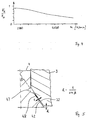
- ein Diagramm, welches Kräfteverhältnisse in Abhängigkeit von der Drehzahl der Zentrifuge darstellt, und
- Fig. 5
- ein Detail einer Querschnittsansicht eines verschmutzten Antriebskopfes und der Hülse der Zentrifuge.
- In
Fig. 1 ist eine Querschnittsansicht einer erfindungsgemäßen Zentrifuge 100 ohne Unterkonstruktion dargestellt. Die Zentrifuge 100 weist einen Rotor 1 auf, welcher eine Vielzahl von Ausnehmungen 2 zur Aufnahme von Probenbehältnissen mit zu zentrifugierendem Gut besitzt. An dem Rotor 1 ist eine Hülse 3 montiert, welche an einem Antriebskopf 4 formschlüssig anliegt. Am Antriebskopf 4 sind zwei vertikal verlaufende Verbindungselemente 5 in Form von Stiften angebracht, welche jeweils in eine Ausnehmung 6 im Rotor 1 formschlüssig eingreifen. Bei der inFig. 1 dargestellten Ausführungsform sind zwei Verbindungselemente 5 dargestellt, welche symmetrisch zur Drehachse 7 angeordnet sind, wobei auch mehr als zwei Verbindungselemente 5 vorgesehen sein können. Bei einer Drehbewegung des Antriebskopfes 4 um die Drehachse 7 übertragen diese Verbindungselemente 5 ein Drehmoment auf den Rotor 1, so dass dieser in Rotation versetzt werden kann. Durch die symmetrische Anordnung der Verbindungselemente 5 wird erreicht, dass das Drehmoment gleichmäßig auf den Rotor 1 übertragen wird. - Zusätzlich weist die Zentrifuge 100 bei dieser Ausführungsform zwei jeweils symmetrisch zur Drehachse 7 angeordnete Kupplungselemente 8 auf, siehe auch
Fig. 2 , welche eine Ansicht entlang der Schnittlinie A-A inFig. 1 zeigt. Die Kupplungselemente 8 sind auf dem Antriebskopf 4 angeordnet und können zur Seite schwenken. Die Schwenkachse 9 ist jeweils durch das Verbindungselement 5 gebildet. - Soll der Rotor 1 mit dem Antriebskopf 4 verbunden werden, wird der Rotor 1 von oben nach unten in Richtung zum Antriebskopf 4 hin bewegt. Dabei trifft die am Rotor 1 montierte Hülse 3 mit ihrer Kegelstumpffläche 32 auf einen jeweiligen äußeren Rand 81 der Kupplungselemente 8, welche jeweils durch eine Druckfeder 45 von einem Anschlag 46 fortgedrückt werden. Durch das Absenken der Hülse 3 mit ihrer Kegelstumpffläche 32 auf die jeweiligen Ränder 81 werden die Kupplungselemente 8 so geschwenkt, dass der jeweilige äußere Rand 81 mit der Mantellinie 44 des Antriebskopfes 4 in Überdeckung kommt. Der langgestreckte Teil 82 jedes Kupplungselementes 8 wird dabei in Richtung zur Drehachse 7 entgegen der Federkraft der Druckfeder 45 geschwenkt.
- Die Hülse 3 bzw. der Rotor 1 kann bei weiterem Absenken in vertikaler Richtung an den Kupplungselementen 8 vorbei gleiten, bis die Kegelstumpffläche 32 auf einer korrespondierenden Kegelstumpffläche 42 des Antriebskopfes 4 aufliegt. Die Kegelstumpffläche 42 dient als Anschlag und begrenzt die Abwärtsbewegung des Rotors 1. In dieser Position können die Kupplungselemente 8, bedingt durch die Federkraft der Druckfeder 45, selbsttätig wieder in ihre vorherige Position zurückschwenken, siehe
Fig. 1 und2 . Der langgestreckte Teil 82 jedes Kupplungselementes 8 steht dabei über der Mantellinie 44 des Antriebskopfes 4 hervor, wobei jedes Kupplungselement 8 die Hülse 3 berührt. Die Kupplungselemente bilden eine Schnellkupplung, wodurch der Rotor rasch und ohne Werkzeug mit dem Antriebskopf verbunden werden kann. Wenn ein Bediener überprüfen möchte, ob der Rotor 1 auf dem Antriebskopf 4 aufsitzt, kann er versuchen, den Rotor 1 nach oben zu ziehen. Da der Rotor 1 bzw. die Hülse 3 an Kupplungselementen 8 anliegt, ist eine vertikale Verlagerung nach oben nicht möglich. Der Bediener erkennt daran, dass der Rotor fest mit dem Antriebskopf 4 verbunden ist. - Die Kupplungselemente 8 können von der Hülse 3 gelöst werden, wenn ein Betätigungselement 10 entlang der Drehachse 7 vertikal nach unten bewegt wird, siehe
Fig. 1 . Das Betätigungselement 10, welches bei dieser Ausführungsform mit einer federnd vorgespannten Drucktaste 11 verbunden ist, besitzt ein konusförmiges Ende, welches an einem Kupplungszahn 84 des Kupplungselementes 8, sieheFig. 2 , angreifen kann. Das konusförmige Ende übt eine Kraft senkrecht zur Drehachse 7 aus, so dass das Kupplungselement 8 derart geschwenkt werden kann, bis der äußere Rand 81 wieder in Überdeckung mit der Mantellinie 44 kommt oder sogar noch weiter in den Antriebskopf hinein verlagert wird. Dann kann der Rotor 1 wieder nach oben gezogen und vom Antriebskopf 4 gelöst werden. - In
Fig. 3 ist in einer Detailansicht der Kontakt des Kupplungselementes 8 mit der Hülse 3 dargestellt. Das Kupplungselement 8 besitzt eine Rampenfläche 83, welche in einem Winkel α zur Horizontalen geneigt ist. Die Rampenfläche 83 berührt formschlüssig die korrespondierende Rampenfläche 33 der Hülse 3, welche ebenfalls in einem Winkel α zur Horizontalen geneigt ist. Das Kupplungselement 8 und die Hülse 3 bilden aufgrund der Rampenflächen 33, 83 jeweils einen Keilkörper. Wirkt auf den Rotor 1 bzw. die Hülse 3 aufgrund einer hohen Umdrehungszahl eine Auftriebskraft F A, stellen sich beim Zusammenwirken mit einem Kupplungselement 8 an dem Flächenpaar 33, 83 die inFig. 3 dargestellten Reaktionskräfte ein. Eine Normalkraft F N wirkt senkrecht zur Rampenfläche 33 auf das Kupplungselement 8, wobei entlang der Rampenfläche eine Haltekraft F H = F N * µ0 wirkt, wobei µ0 der Haftreibwert ist. Der Haltekraft F H steht eine Rückstellkraft F R des Kupplungselementes 8 entgegen. Durch die Auftriebskraft F A kann das Kupplungselement 8 nicht zur - Seite geschwenkt werden, wenn zwischen dem Winkel α und einem Reibwert µ0 folgende Beziehung eingehalten wird:

- Bei einem Haftreibwert von 0,3, wie er bei einer Stahl/Stahl-Paarung bei trockener Oberfläche (Festkörperreibung) vorliegt, muss somit der Winkel α kleiner als 16,7° sein. Eine Selbsthemmung tritt dann auch beim Stillstand des Rotors auf. Wenn das Kupplungselement 8 mit einer Druckfeder 45 zur Seite gedrückt wird, wirkt auf das Kupplungselement 8 zusätzlich zur Haltekraft F H noch eine Federkraft F F. Bei einer Rotation des Rotors 1 kommt noch eine drehzahlabhängige Zentrifugalkraft F Z hinzu, so dass sich die gesamte Haltekraft F H ges bei einem rotierenden Rotor berechnet zu:

- In
Fig. 4 ist dargestellt, wie sich das Verhältnis aus F R zu F H in Abhängigkeit von der Drehzahl n verändert. Bei einem Verhältnis von F R : F H = 1 liegt der Grenzfall vor, bei dem gerade noch eine Selbsthemmung erreicht wird. Bei einem Winkel α = 15° ist bei der hier gewählten Werkstoffpaarung mit einem Haftreibwert von jeweils 0,3 das Verhältnis aus F R : F H kleiner als 1, sieheFig. 4 . Mit zunehmender Drehzahl erhöht sich der Betrag, der von der Zentrifugalkraft beigetragen wird, so dass das Verhältnis aus F R : F H bei zunehmender Drehzahl n abnimmt. Die Verriegelung des Rotors wird mit zunehmender Drehzahl somit immer sicherer. - In
Fig. 5 ist ein Detail im Bereich des Kontaktes zwischen Antriebskopf 4 und Hülse 3 dargestellt. Der Antriebskopf 4 besitzt im Bereich des Kegelstumpfes einen Schmutzauftrag 48 der Dicke t. Wird die Hülse 3 bzw. der Rotor 1 abgesenkt, erreicht die Kegelstumpffläche 32 der Hülse nicht mehr die Kegelstumpffläche 42 des Antriebskopfes 4, sondern verbleibt in einer Höhe, die um den Betrag h höher ist, als wenn keine Verschmutzung vorliegen würde. Die Empfindlichkeit gegenüber einem solchen Schmutzauftrag ist umso geringer, je größer der Kegelstumpfwinkel β ist, da somit der durch die Kupplungselemente zu überbrückende Höhenunterschied zwischen einem sauberen und einem verschmutzten Konus geringer wird. Da der verfügbare Platz für die Bewegung der Kupplungselemente 8 begrenzt ist und man von einer Verschmutzung von maximal 0,5 mm ausgehen kann, beträgt bei dieser Ausführungsform der Kegelstumpfwinkel etwa 35°. - Der Einfluss einer Verschmutzung an der Zylinderfläche 41 kann gering gehalten werden, wenn im Bereich der Kegelstumpffläche 42 des Antriebskopfes Ausnehmungen 47 vorgesehen sind. Sie nehmen einen im Bereich der Zylinderfläche 41 vorhandenen Schmutzbelag beim Absenken der Hülse 3 auf und verhindern, dass er sich zusätzlich auf der Kegelstumpffläche 42 ansammelt.
Claims (10)
- Zentrifuge (100) mit einem Antriebskopf (4), der mit einem Antrieb verbindbar ist, einem Rotor (1), der sich am Antriebskopf (4) lösbar montieren lässt, mindestens einem Verbindungselement (5), mit dem der Antriebskopf (4) mit dem Rotor (1) drehfest verbindbar ist, und mindestens einem Kupplungselement (8), welches am Antriebskopf (4) angebracht ist und eine axiale Kraft auf den Rotor (1) so ausüben kann, dass sich der Rotor (1) axial fixieren lässt, wobei die axiale Kraft bei ansteigender Drehgeschwindigkeit des Antriebskopfes (4) zunimmt, wobei das Kupplungselement (8) auf den Rotor (1) die axiale Kraft mittels einer Rampenfläche (83) überträgt,
wobei die Rampenfläche in einem Winkel (α) zur Horizontalen in einem Bereich von größer 0° bis 15° geneigt ist, wobei der Antriebskopf (4) eine Mantelfläche besitzt, welche eine Zylinderfläche (41) und eine Kegelstumpffläche (42) aufweist, wobei die Mantelfläche an einer korrespondierenden Haltefläche mit einer Zylinderfläche (31) und einer Kegelstumpffläche (32) des Rotors (1) formschlüssig anliegt, wenn der Rotor (1) mit dem Antriebskopf (4) montiert ist,
dadurch gekennzeichnet, dass
die Zylinderfläche (41) des Antriebskopfes (4) eine Länge aufweist, welche mindestens ein Viertel der Länge der Haltefläche ist, wobei ausschließlich die Zylinderfläche (41) als Führung des Rotors (1) in axialer Richtung und die Kegelstumpffläche (42) ausschließlich als Anschlag in axialer Richtung ausgebildet sind. - Zentrifuge (100) nach Anspruch 1,
dadurch gekennzeichnet, dass
das Kupplungselement (8) um eine Schwenkachse (9) schwenkbar ist zwischen einer Entriegelungsposition, in der es in den Antriebskopf (4) eingeschwenkt ist, wodurch der Rotor (1) bezüglich des Antriebskopfes (4) entriegelt ist, und zwischen einer Verriegelungsposition, in der das Kupplungselement (8) mit der Rampenfläche (83) von einer Mantelfläche (44) des Antriebskopfes (4) vorsteht und auf den Rotor (1) eine axiale Kraft überträgt, wodurch der Rotor (1) bezüglich des Antriebskopfes (4) verriegelt ist. - Zentrifuge (100) nach Anspruch 2,
dadurch gekennzeichnet, dass
das Kupplungselement (8) federnd so vorgespannt ist, dass es bei Stillstand des Rotors (1) die Verriegelungsposition einnimmt. - Zentrifuge (100) nach Anspruch 2 oder 3,
dadurch gekennzeichnet, dass
in der Schwenkachse (9) des Kupplungselementes (8) das Verbindungselement (5) angeordnet ist, mit dem der Antriebskopf (4) mit dem Rotor (1) drehfest verbindbar ist. - Zentrifuge (100) nach einem der vorherigen Ansprüche,
dadurch gekennzeichnet, dass
das Kupplungselement (8) einen Kupplungszahn (84) aufweist, welcher mit einem Betätigungselement (10) derart zusammenwirken kann, dass sich auf das Kupplungselement (8) eine Schwenkbewegung ausüben lässt, so dass eine Verlagerung des Kupplungselementes (8) von der Verriegelungsposition in die Entriegelungsposition oder umgekehrt durchführbar ist. - Zentrifuge (100) nach Anspruch 5,
dadurch gekennzeichnet, dass
sich das Betätigungselement (10) in der Drehachse (7) der Zentrifuge (100) anordnen lässt und an einem Ende kegelförmig ausgebildet ist, so dass bei axialer Verlagerung des Betätigungselementes (10) das kegelförmige Ende mit dem Kupplungszahn (84) des Kupplungselementes (8) wechselwirken kann. - Zentrifuge (100) nach einem der vorherigen Ansprüche,
dadurch gekennzeichnet, dass
die axiale Kraft auf eine Hülse (3) wirkt, welche am Rotor (1) fest montiert ist. - Zentrifuge (100) nach Anspruch 1,
dadurch gekennzeichnet, dass
die Kegelstumpffläche (42) des Antriebskopfes (4) einen Kegelwinkel (β) von 15° bis 40° zur Drehachse (7) aufweist. - Zentrifuge (100) nach Anspruch 1 oder 8,
dadurch gekennzeichnet, dass
die Zylinderfläche (41) oder Kegelstumpffläche (42) des Antriebskopfes (4) mindestens eine Ausnehmung (4), insbesondere einen Quer-Einstich, aufweist. - Zentrifuge (100) nach einem der Ansprüche 1, 8 oder 9,
dadurch gekennzeichnet, dass
die Zylinderfläche (41) des Antriebskopfes (4) zur Haltefläche des Rotors (1) oder der Hülse (3) als Spielpassung ausgebildet ist, die eine sichere Führung des Rotors bei Stillstand und bei hoher Drehgeschwindigkeit sicherstellt.
Applications Claiming Priority (2)
| Application Number | Priority Date | Filing Date | Title |
|---|---|---|---|
| DE102008045556A DE102008045556A1 (de) | 2008-09-03 | 2008-09-03 | Zentrifuge mit einem Kupplungselement zur axialen Verriegelung eines Rotors |
| PCT/EP2009/006398 WO2010025922A1 (de) | 2008-09-03 | 2009-09-03 | Zentrifuge mit einem kupplungselement zur axialen verriegelung eines rotors |
Publications (2)
| Publication Number | Publication Date |
|---|---|
| EP2321058A1 EP2321058A1 (de) | 2011-05-18 |
| EP2321058B1 true EP2321058B1 (de) | 2016-04-27 |
Family
ID=41172422
Family Applications (1)
| Application Number | Title | Priority Date | Filing Date |
|---|---|---|---|
| EP09778316.1A Active EP2321058B1 (de) | 2008-09-03 | 2009-09-03 | Zentrifuge mit einem kupplungselement zur axialen verriegelung eines rotors |
Country Status (6)
| Country | Link |
|---|---|
| US (1) | US8678987B2 (de) |
| EP (1) | EP2321058B1 (de) |
| JP (1) | JP5379854B2 (de) |
| CN (1) | CN102176975B (de) |
| DE (1) | DE102008045556A1 (de) |
| WO (1) | WO2010025922A1 (de) |
Families Citing this family (22)
| Publication number | Priority date | Publication date | Assignee | Title |
|---|---|---|---|---|
| DE102008045556A1 (de) * | 2008-09-03 | 2010-03-04 | Thermo Electron Led Gmbh | Zentrifuge mit einem Kupplungselement zur axialen Verriegelung eines Rotors |
| FR2951964B1 (fr) * | 2009-11-04 | 2012-04-06 | Bms Internat | Centrifugeuse comprenant des moyens d'indication visuelle et/ou tactile du montage correct du rotor sur l'arbre d'entrainement, et rotor correspondant |
| DE202010014803U1 (de) | 2010-11-01 | 2010-12-30 | Sigma Laborzentrifugen Gmbh | Rotorlagerung für eine Laborzentrifuge |
| DE102012011531B4 (de) * | 2012-06-08 | 2016-11-10 | Thermo Electron Led Gmbh | Set aus Antriebskopf und Nabe zur lösbaren Verbindung eines Antriebes mit einem Rotor einer Zentrifuge für einen weiten Drehzahlbereich |
| FR3005273A1 (fr) * | 2013-05-02 | 2014-11-07 | Afi Centrifuge | Centrifugeuse de laboratoire comprenant des moyens pour le verrouillage en translation d'un rotor sur un arbre moteur d'entrainement |
| FR3010886B1 (fr) * | 2013-09-20 | 2015-10-30 | Santos | Dispositif d'entrainement d'un outil rotatif pour appareil de traitement alimentaire, et appareil de traitement alimentaire pourvu d'un tel dispositif d'entrainement |
| DE102014002126B4 (de) * | 2014-02-17 | 2019-01-17 | Thermo Electron Led Gmbh | Antriebskopf zur lösbaren Verbindung eines Antriebes mit einem Rotor einer Zentrifuge, diesen umfassendes Set und Zentrifuge |
| DE102014008219B4 (de) | 2014-05-28 | 2018-08-02 | Thermo Electron Led Gmbh | Antriebskopf zur lösbaren Verbindung eines Antriebes mit einem Rotor einer Zentrifuge, diesen umfassendes Set und Zentrifuge |
| JP6228895B2 (ja) * | 2014-06-16 | 2017-11-08 | 株式会社久保田製作所 | 遠心分離機とロータ体 |
| CN104014269A (zh) * | 2014-06-28 | 2014-09-03 | 葛华鹏 | 一种离心式试管摇匀装置 |
| DE102014112501B4 (de) * | 2014-08-29 | 2017-07-27 | Andreas Hettich Gmbh & Co. Kg | Zentrifuge |
| EP3012027B1 (de) | 2014-10-21 | 2016-09-21 | Sigma Laborzentrifugen GmbH | Zentrifugalkraftbetätigte kupplungseinrichtung für eine laborzentrifuge |
| DE102015113854A1 (de) * | 2015-08-20 | 2017-02-23 | Andreas Hettich Gmbh & Co. Kg | Rotor einer Zentrifuge |
| DE102015113855A1 (de) * | 2015-08-20 | 2017-02-23 | Andreas Hettich Gmbh & Co. Kg | Rotor einer Zentrifuge |
| CN105342707B (zh) * | 2015-11-13 | 2018-02-23 | 张稳存 | 一种精密手术针旋转离心盘 |
| US10532366B2 (en) * | 2016-07-13 | 2020-01-14 | Kubota Manufacturing Corporation | Rotor attachment structure and centrifuge |
| DE102017130787A1 (de) * | 2017-12-20 | 2019-06-27 | Eppendorf Ag | Zentrifugenrotor |
| JP6953336B2 (ja) * | 2018-03-22 | 2021-10-27 | 本田技研工業株式会社 | 連結具 |
| EP3669993A1 (de) * | 2018-12-18 | 2020-06-24 | Eppendorf AG | Verbindungskonstruktion |
| EP3669992A1 (de) * | 2018-12-18 | 2020-06-24 | Eppendorf AG | Verbindungskonstruktion |
| CN109967269A (zh) * | 2019-04-30 | 2019-07-05 | 中国工程物理研究院总体工程研究所 | 一种离心机转臂支撑及传动结构 |
| CN113522540B (zh) * | 2021-09-13 | 2022-02-18 | 深圳市瑞沃德生命科技有限公司 | 一种转子及具有其的离心机 |
Family Cites Families (17)
| Publication number | Priority date | Publication date | Assignee | Title |
|---|---|---|---|---|
| US3779451A (en) | 1971-11-22 | 1973-12-18 | Int Equipment Co | Flexible shaft stabilizer |
| GB1557231A (en) * | 1976-02-07 | 1979-12-05 | Fisons Ltd | Mounting of a centrifuge rotor |
| JPS6039089Y2 (ja) * | 1982-02-17 | 1985-11-22 | 株式会社久保田製作所 | ロ−タ種類自動判別装置 |
| US4753631A (en) * | 1986-11-03 | 1988-06-28 | E. I. Du Pont De Nemours And Company | Speed limiting arrangement for a centrifuge rotor having an axial mounting bolt |
| US4927406A (en) * | 1988-12-15 | 1990-05-22 | Beckman Instruments, Inc. | Spring biased drive socket insert for centrifuge rotors |
| FR2694509B1 (fr) * | 1992-08-04 | 1994-10-07 | Jouan | Centrifugeur comportant un arbre d'entraînement de rotor à joint élastique d'amortissement et arbre correspondant. |
| US5443438A (en) * | 1994-07-29 | 1995-08-22 | Beckman Instruments, Inc. | Centrifuge drive-to-rotor assembly |
| FR2727037A1 (fr) * | 1994-11-21 | 1996-05-24 | Jouan | Centrifugeuse a rotor demontable et a dispositif de blocage axial du rotor sur l'arbre d'entrainement |
| JP3950520B2 (ja) * | 1997-07-25 | 2007-08-01 | 株式会社トミー精工 | 遠心分離機 |
| FR2770154B1 (fr) * | 1997-10-23 | 1999-11-26 | Jouan | Centrifugeuse a rotor demontable et a dispositif de blocage axial du rotor sur une tete d'entrainement, et rotor pour une telle centrifugeuse |
| JP3861476B2 (ja) * | 1998-09-30 | 2006-12-20 | 日立工機株式会社 | 遠心分離機 |
| US6183408B1 (en) * | 1999-05-03 | 2001-02-06 | Beckman Coulter, Inc. | Rotor shaft assembly having non-linear stiffness |
| DE102004062232B4 (de) * | 2004-12-23 | 2013-01-10 | Thermo Electron Led Gmbh | Rotor für Laborzentrifugen |
| DE102005014218B4 (de) * | 2005-03-29 | 2008-03-06 | Thermo Electron Led Gmbh | Befestigungsvorrichtung eines Deckels für einen Zentrifugenrotor |
| DE102008045556A1 (de) * | 2008-09-03 | 2010-03-04 | Thermo Electron Led Gmbh | Zentrifuge mit einem Kupplungselement zur axialen Verriegelung eines Rotors |
| JP5212907B2 (ja) * | 2008-12-16 | 2013-06-19 | 日立工機株式会社 | 遠心分離機 |
| FR2951965B1 (fr) * | 2009-11-04 | 2012-04-06 | Bms Internat | Centrifugeuse integrant des moyens tachymetriques montes dans une partie superieure de l'enceinte, en particulier montes sur le couvercle |
-
2008
- 2008-09-03 DE DE102008045556A patent/DE102008045556A1/de not_active Withdrawn
-
2009
- 2009-09-03 CN CN200980140066.8A patent/CN102176975B/zh active Active
- 2009-09-03 US US13/059,989 patent/US8678987B2/en active Active
- 2009-09-03 WO PCT/EP2009/006398 patent/WO2010025922A1/de active Application Filing
- 2009-09-03 JP JP2011524273A patent/JP5379854B2/ja active Active
- 2009-09-03 EP EP09778316.1A patent/EP2321058B1/de active Active
Also Published As
| Publication number | Publication date |
|---|---|
| WO2010025922A1 (de) | 2010-03-11 |
| CN102176975B (zh) | 2014-11-12 |
| JP2012501817A (ja) | 2012-01-26 |
| JP5379854B2 (ja) | 2013-12-25 |
| US8678987B2 (en) | 2014-03-25 |
| EP2321058A1 (de) | 2011-05-18 |
| US20110212822A1 (en) | 2011-09-01 |
| DE102008045556A1 (de) | 2010-03-04 |
| CN102176975A (zh) | 2011-09-07 |
Similar Documents
| Publication | Publication Date | Title |
|---|---|---|
| EP2321058B1 (de) | Zentrifuge mit einem kupplungselement zur axialen verriegelung eines rotors | |
| EP3012027B1 (de) | Zentrifugalkraftbetätigte kupplungseinrichtung für eine laborzentrifuge | |
| EP0500489B1 (de) | Werkzeug und Werkzeughalter für Handwerkzeuggeräte | |
| EP3186009B1 (de) | Schnellverschluss einer zentrifuge | |
| EP3021974B1 (de) | Zentrifuge | |
| DE102012011531B4 (de) | Set aus Antriebskopf und Nabe zur lösbaren Verbindung eines Antriebes mit einem Rotor einer Zentrifuge für einen weiten Drehzahlbereich | |
| DE06851653T1 (de) | Fliehkraftlager mit gleichmässigem kippmoment | |
| CH655273A5 (de) | Werkzeughalter fuer bohr- und schlagbohrgeraete. | |
| CH651489A5 (de) | Stichsaege. | |
| DE2501954A1 (de) | Vorrichtung zum kuppeln von zwei umlaufenden koaxialwellen mit waehrend des betriebes veraenderbarer winkelversetzung, insbesondere fuer die steuerung der ventile in brennkraftmaschinen | |
| DE2905363C2 (de) | Scherbolzenkupplung | |
| EP0347611A2 (de) | Bogengreifer an Bogenrotationsdruckmaschinen | |
| EP2097201B1 (de) | Werkzeugkupplung | |
| EP3841254B1 (de) | Schaufelrad mit einer entriegelungseinrichtung und verfahren zum umschwenken von schaufeln eines schaufelrades | |
| EP3993978B1 (de) | Ringsäge mit wasserspülung | |
| DE102017213047A1 (de) | Justiereinrichtung für ein zerspanungswerkzeug und zerspanungswerkzeug mit einer justiereinrichtung | |
| WO2016107705A1 (de) | Dreheinheit für einen rotor einer dualen zentrifuge | |
| EP3325835B1 (de) | Wellenverbindungsvorrichtung und anordnung zur drehverbindung einer belastungsmaschine eines prüfstandes mit einem prüfling | |
| DE579859C (de) | Brennstoff-Einspritzpumpe | |
| DE2328983C3 (de) | Zentrifuge | |
| DE102021121259A1 (de) | Zentrifuge | |
| EP2632347A1 (de) | Chirurgisches instrument | |
| DE3219295C2 (de) | Spannfutter für Drehmaschinen | |
| DE3133344C1 (de) | Antriebsvorrichtung für ein Schaufelrad | |
| DE2212664C3 (de) | Einrichtung zur Drehbearbeitung von sphärischen Ringflächen |
Legal Events
| Date | Code | Title | Description |
|---|---|---|---|
| PUAI | Public reference made under article 153(3) epc to a published international application that has entered the european phase |
Free format text: ORIGINAL CODE: 0009012 |
|
| 17P | Request for examination filed |
Effective date: 20110214 |
|
| AK | Designated contracting states |
Kind code of ref document: A1 Designated state(s): AT BE BG CH CY CZ DE DK EE ES FI FR GB GR HR HU IE IS IT LI LT LU LV MC MK MT NL NO PL PT RO SE SI SK SM TR |
|
| AX | Request for extension of the european patent |
Extension state: AL BA RS |
|
| DAX | Request for extension of the european patent (deleted) | ||
| 17Q | First examination report despatched |
Effective date: 20130429 |
|
| GRAP | Despatch of communication of intention to grant a patent |
Free format text: ORIGINAL CODE: EPIDOSNIGR1 |
|
| INTG | Intention to grant announced |
Effective date: 20160120 |
|
| GRAS | Grant fee paid |
Free format text: ORIGINAL CODE: EPIDOSNIGR3 |
|
| GRAA | (expected) grant |
Free format text: ORIGINAL CODE: 0009210 |
|
| AK | Designated contracting states |
Kind code of ref document: B1 Designated state(s): AT BE BG CH CY CZ DE DK EE ES FI FR GB GR HR HU IE IS IT LI LT LU LV MC MK MT NL NO PL PT RO SE SI SK SM TR |
|
| REG | Reference to a national code |
Ref country code: GB Ref legal event code: FG4D Free format text: NOT ENGLISH |
|
| REG | Reference to a national code |
Ref country code: CH Ref legal event code: EP |
|
| REG | Reference to a national code |
Ref country code: AT Ref legal event code: REF Ref document number: 794124 Country of ref document: AT Kind code of ref document: T Effective date: 20160515 |
|
| REG | Reference to a national code |
Ref country code: IE Ref legal event code: FG4D Free format text: LANGUAGE OF EP DOCUMENT: GERMAN |
|
| REG | Reference to a national code |
Ref country code: DE Ref legal event code: R096 Ref document number: 502009012499 Country of ref document: DE |
|
| REG | Reference to a national code |
Ref country code: LT Ref legal event code: MG4D |
|
| REG | Reference to a national code |
Ref country code: NL Ref legal event code: MP Effective date: 20160427 |
|
| PG25 | Lapsed in a contracting state [announced via postgrant information from national office to epo] |
Ref country code: NL Free format text: LAPSE BECAUSE OF FAILURE TO SUBMIT A TRANSLATION OF THE DESCRIPTION OR TO PAY THE FEE WITHIN THE PRESCRIBED TIME-LIMIT Effective date: 20160427 |
|
| PG25 | Lapsed in a contracting state [announced via postgrant information from national office to epo] |
Ref country code: FI Free format text: LAPSE BECAUSE OF FAILURE TO SUBMIT A TRANSLATION OF THE DESCRIPTION OR TO PAY THE FEE WITHIN THE PRESCRIBED TIME-LIMIT Effective date: 20160427 Ref country code: PL Free format text: LAPSE BECAUSE OF FAILURE TO SUBMIT A TRANSLATION OF THE DESCRIPTION OR TO PAY THE FEE WITHIN THE PRESCRIBED TIME-LIMIT Effective date: 20160427 Ref country code: NO Free format text: LAPSE BECAUSE OF FAILURE TO SUBMIT A TRANSLATION OF THE DESCRIPTION OR TO PAY THE FEE WITHIN THE PRESCRIBED TIME-LIMIT Effective date: 20160727 Ref country code: LT Free format text: LAPSE BECAUSE OF FAILURE TO SUBMIT A TRANSLATION OF THE DESCRIPTION OR TO PAY THE FEE WITHIN THE PRESCRIBED TIME-LIMIT Effective date: 20160427 |
|
| PG25 | Lapsed in a contracting state [announced via postgrant information from national office to epo] |
Ref country code: GR Free format text: LAPSE BECAUSE OF FAILURE TO SUBMIT A TRANSLATION OF THE DESCRIPTION OR TO PAY THE FEE WITHIN THE PRESCRIBED TIME-LIMIT Effective date: 20160728 Ref country code: LV Free format text: LAPSE BECAUSE OF FAILURE TO SUBMIT A TRANSLATION OF THE DESCRIPTION OR TO PAY THE FEE WITHIN THE PRESCRIBED TIME-LIMIT Effective date: 20160427 Ref country code: SE Free format text: LAPSE BECAUSE OF FAILURE TO SUBMIT A TRANSLATION OF THE DESCRIPTION OR TO PAY THE FEE WITHIN THE PRESCRIBED TIME-LIMIT Effective date: 20160427 Ref country code: ES Free format text: LAPSE BECAUSE OF FAILURE TO SUBMIT A TRANSLATION OF THE DESCRIPTION OR TO PAY THE FEE WITHIN THE PRESCRIBED TIME-LIMIT Effective date: 20160427 Ref country code: PT Free format text: LAPSE BECAUSE OF FAILURE TO SUBMIT A TRANSLATION OF THE DESCRIPTION OR TO PAY THE FEE WITHIN THE PRESCRIBED TIME-LIMIT Effective date: 20160829 Ref country code: HR Free format text: LAPSE BECAUSE OF FAILURE TO SUBMIT A TRANSLATION OF THE DESCRIPTION OR TO PAY THE FEE WITHIN THE PRESCRIBED TIME-LIMIT Effective date: 20160427 |
|
| PG25 | Lapsed in a contracting state [announced via postgrant information from national office to epo] |
Ref country code: IT Free format text: LAPSE BECAUSE OF FAILURE TO SUBMIT A TRANSLATION OF THE DESCRIPTION OR TO PAY THE FEE WITHIN THE PRESCRIBED TIME-LIMIT Effective date: 20160427 |
|
| REG | Reference to a national code |
Ref country code: DE Ref legal event code: R097 Ref document number: 502009012499 Country of ref document: DE |
|
| PG25 | Lapsed in a contracting state [announced via postgrant information from national office to epo] |
Ref country code: RO Free format text: LAPSE BECAUSE OF FAILURE TO SUBMIT A TRANSLATION OF THE DESCRIPTION OR TO PAY THE FEE WITHIN THE PRESCRIBED TIME-LIMIT Effective date: 20160427 Ref country code: CZ Free format text: LAPSE BECAUSE OF FAILURE TO SUBMIT A TRANSLATION OF THE DESCRIPTION OR TO PAY THE FEE WITHIN THE PRESCRIBED TIME-LIMIT Effective date: 20160427 Ref country code: DK Free format text: LAPSE BECAUSE OF FAILURE TO SUBMIT A TRANSLATION OF THE DESCRIPTION OR TO PAY THE FEE WITHIN THE PRESCRIBED TIME-LIMIT Effective date: 20160427 Ref country code: EE Free format text: LAPSE BECAUSE OF FAILURE TO SUBMIT A TRANSLATION OF THE DESCRIPTION OR TO PAY THE FEE WITHIN THE PRESCRIBED TIME-LIMIT Effective date: 20160427 Ref country code: SK Free format text: LAPSE BECAUSE OF FAILURE TO SUBMIT A TRANSLATION OF THE DESCRIPTION OR TO PAY THE FEE WITHIN THE PRESCRIBED TIME-LIMIT Effective date: 20160427 |
|
| PG25 | Lapsed in a contracting state [announced via postgrant information from national office to epo] |
Ref country code: BE Free format text: LAPSE BECAUSE OF NON-PAYMENT OF DUE FEES Effective date: 20160930 Ref country code: SM Free format text: LAPSE BECAUSE OF FAILURE TO SUBMIT A TRANSLATION OF THE DESCRIPTION OR TO PAY THE FEE WITHIN THE PRESCRIBED TIME-LIMIT Effective date: 20160427 |
|
| PLBE | No opposition filed within time limit |
Free format text: ORIGINAL CODE: 0009261 |
|
| STAA | Information on the status of an ep patent application or granted ep patent |
Free format text: STATUS: NO OPPOSITION FILED WITHIN TIME LIMIT |
|
| 26N | No opposition filed |
Effective date: 20170130 |
|
| PG25 | Lapsed in a contracting state [announced via postgrant information from national office to epo] |
Ref country code: MC Free format text: LAPSE BECAUSE OF FAILURE TO SUBMIT A TRANSLATION OF THE DESCRIPTION OR TO PAY THE FEE WITHIN THE PRESCRIBED TIME-LIMIT Effective date: 20160427 |
|
| REG | Reference to a national code |
Ref country code: CH Ref legal event code: PL |
|
| PG25 | Lapsed in a contracting state [announced via postgrant information from national office to epo] |
Ref country code: SI Free format text: LAPSE BECAUSE OF FAILURE TO SUBMIT A TRANSLATION OF THE DESCRIPTION OR TO PAY THE FEE WITHIN THE PRESCRIBED TIME-LIMIT Effective date: 20160427 |
|
| REG | Reference to a national code |
Ref country code: IE Ref legal event code: MM4A |
|
| REG | Reference to a national code |
Ref country code: FR Ref legal event code: ST Effective date: 20170531 |
|
| PG25 | Lapsed in a contracting state [announced via postgrant information from national office to epo] |
Ref country code: FR Free format text: LAPSE BECAUSE OF NON-PAYMENT OF DUE FEES Effective date: 20160930 Ref country code: CH Free format text: LAPSE BECAUSE OF NON-PAYMENT OF DUE FEES Effective date: 20160930 Ref country code: LI Free format text: LAPSE BECAUSE OF NON-PAYMENT OF DUE FEES Effective date: 20160930 Ref country code: IE Free format text: LAPSE BECAUSE OF NON-PAYMENT OF DUE FEES Effective date: 20160903 |
|
| PG25 | Lapsed in a contracting state [announced via postgrant information from national office to epo] |
Ref country code: LU Free format text: LAPSE BECAUSE OF NON-PAYMENT OF DUE FEES Effective date: 20160903 |
|
| REG | Reference to a national code |
Ref country code: AT Ref legal event code: MM01 Ref document number: 794124 Country of ref document: AT Kind code of ref document: T Effective date: 20160903 |
|
| REG | Reference to a national code |
Ref country code: BE Ref legal event code: MM Effective date: 20160930 |
|
| PG25 | Lapsed in a contracting state [announced via postgrant information from national office to epo] |
Ref country code: AT Free format text: LAPSE BECAUSE OF NON-PAYMENT OF DUE FEES Effective date: 20160903 |
|
| PG25 | Lapsed in a contracting state [announced via postgrant information from national office to epo] |
Ref country code: CY Free format text: LAPSE BECAUSE OF FAILURE TO SUBMIT A TRANSLATION OF THE DESCRIPTION OR TO PAY THE FEE WITHIN THE PRESCRIBED TIME-LIMIT Effective date: 20160427 Ref country code: HU Free format text: LAPSE BECAUSE OF FAILURE TO SUBMIT A TRANSLATION OF THE DESCRIPTION OR TO PAY THE FEE WITHIN THE PRESCRIBED TIME-LIMIT; INVALID AB INITIO Effective date: 20090903 |
|
| PG25 | Lapsed in a contracting state [announced via postgrant information from national office to epo] |
Ref country code: IS Free format text: LAPSE BECAUSE OF FAILURE TO SUBMIT A TRANSLATION OF THE DESCRIPTION OR TO PAY THE FEE WITHIN THE PRESCRIBED TIME-LIMIT Effective date: 20160427 Ref country code: MK Free format text: LAPSE BECAUSE OF FAILURE TO SUBMIT A TRANSLATION OF THE DESCRIPTION OR TO PAY THE FEE WITHIN THE PRESCRIBED TIME-LIMIT Effective date: 20160427 Ref country code: TR Free format text: LAPSE BECAUSE OF FAILURE TO SUBMIT A TRANSLATION OF THE DESCRIPTION OR TO PAY THE FEE WITHIN THE PRESCRIBED TIME-LIMIT Effective date: 20160427 Ref country code: MT Free format text: LAPSE BECAUSE OF FAILURE TO SUBMIT A TRANSLATION OF THE DESCRIPTION OR TO PAY THE FEE WITHIN THE PRESCRIBED TIME-LIMIT Effective date: 20160427 |
|
| PG25 | Lapsed in a contracting state [announced via postgrant information from national office to epo] |
Ref country code: BG Free format text: LAPSE BECAUSE OF FAILURE TO SUBMIT A TRANSLATION OF THE DESCRIPTION OR TO PAY THE FEE WITHIN THE PRESCRIBED TIME-LIMIT Effective date: 20160427 |
|
| PGFP | Annual fee paid to national office [announced via postgrant information from national office to epo] |
Ref country code: GB Payment date: 20190830 Year of fee payment: 11 |
|
| GBPC | Gb: european patent ceased through non-payment of renewal fee |
Effective date: 20200903 |
|
| PG25 | Lapsed in a contracting state [announced via postgrant information from national office to epo] |
Ref country code: GB Free format text: LAPSE BECAUSE OF NON-PAYMENT OF DUE FEES Effective date: 20200903 |
|
| REG | Reference to a national code |
Ref country code: DE Ref legal event code: R082 Ref document number: 502009012499 Country of ref document: DE Representative=s name: BOULT WADE TENNANT LLP, DE Ref country code: DE Ref legal event code: R082 Ref document number: 502009012499 Country of ref document: DE |
|
| PGFP | Annual fee paid to national office [announced via postgrant information from national office to epo] |
Ref country code: DE Payment date: 20230918 Year of fee payment: 15 |
|
| REG | Reference to a national code |
Ref country code: DE Ref legal event code: R082 Ref document number: 502009012499 Country of ref document: DE Representative=s name: BOULT WADE TENNANT LLP, DE |