EP2319652B1 - Verfahren zur Verbinden metallischer Elemente und gebundener metallischer Körper - Google Patents
Verfahren zur Verbinden metallischer Elemente und gebundener metallischer Körper Download PDFInfo
- Publication number
- EP2319652B1 EP2319652B1 EP10014202.5A EP10014202A EP2319652B1 EP 2319652 B1 EP2319652 B1 EP 2319652B1 EP 10014202 A EP10014202 A EP 10014202A EP 2319652 B1 EP2319652 B1 EP 2319652B1
- Authority
- EP
- European Patent Office
- Prior art keywords
- diameter section
- inner diameter
- metallic member
- section
- metallic
- Prior art date
- Legal status (The legal status is an assumption and is not a legal conclusion. Google has not performed a legal analysis and makes no representation as to the accuracy of the status listed.)
- Active
Links
Images

Classifications
-
- B—PERFORMING OPERATIONS; TRANSPORTING
- B23—MACHINE TOOLS; METAL-WORKING NOT OTHERWISE PROVIDED FOR
- B23K—SOLDERING OR UNSOLDERING; WELDING; CLADDING OR PLATING BY SOLDERING OR WELDING; CUTTING BY APPLYING HEAT LOCALLY, e.g. FLAME CUTTING; WORKING BY LASER BEAM
- B23K11/00—Resistance welding; Severing by resistance heating
- B23K11/08—Seam welding not restricted to one of the preceding subgroups
- B23K11/093—Seam welding not restricted to one of the preceding subgroups for curved planar seams
-
- B—PERFORMING OPERATIONS; TRANSPORTING
- B23—MACHINE TOOLS; METAL-WORKING NOT OTHERWISE PROVIDED FOR
- B23K—SOLDERING OR UNSOLDERING; WELDING; CLADDING OR PLATING BY SOLDERING OR WELDING; CUTTING BY APPLYING HEAT LOCALLY, e.g. FLAME CUTTING; WORKING BY LASER BEAM
- B23K33/00—Specially-profiled edge portions of workpieces for making soldering or welding connections; Filling the seams formed thereby
- B23K33/004—Filling of continuous seams
- B23K33/006—Filling of continuous seams for cylindrical workpieces
-
- F—MECHANICAL ENGINEERING; LIGHTING; HEATING; WEAPONS; BLASTING
- F16—ENGINEERING ELEMENTS AND UNITS; GENERAL MEASURES FOR PRODUCING AND MAINTAINING EFFECTIVE FUNCTIONING OF MACHINES OR INSTALLATIONS; THERMAL INSULATION IN GENERAL
- F16H—GEARING
- F16H48/00—Differential gearings
- F16H48/38—Constructional details
- F16H2048/382—Methods for manufacturing differential gearings
-
- F—MECHANICAL ENGINEERING; LIGHTING; HEATING; WEAPONS; BLASTING
- F16—ENGINEERING ELEMENTS AND UNITS; GENERAL MEASURES FOR PRODUCING AND MAINTAINING EFFECTIVE FUNCTIONING OF MACHINES OR INSTALLATIONS; THERMAL INSULATION IN GENERAL
- F16H—GEARING
- F16H48/00—Differential gearings
- F16H48/38—Constructional details
- F16H2048/385—Constructional details of the ring or crown gear
-
- F—MECHANICAL ENGINEERING; LIGHTING; HEATING; WEAPONS; BLASTING
- F16—ENGINEERING ELEMENTS AND UNITS; GENERAL MEASURES FOR PRODUCING AND MAINTAINING EFFECTIVE FUNCTIONING OF MACHINES OR INSTALLATIONS; THERMAL INSULATION IN GENERAL
- F16H—GEARING
- F16H48/00—Differential gearings
- F16H48/06—Differential gearings with gears having orbital motion
- F16H48/08—Differential gearings with gears having orbital motion comprising bevel gears
-
- F—MECHANICAL ENGINEERING; LIGHTING; HEATING; WEAPONS; BLASTING
- F16—ENGINEERING ELEMENTS AND UNITS; GENERAL MEASURES FOR PRODUCING AND MAINTAINING EFFECTIVE FUNCTIONING OF MACHINES OR INSTALLATIONS; THERMAL INSULATION IN GENERAL
- F16H—GEARING
- F16H48/00—Differential gearings
- F16H48/38—Constructional details
- F16H48/40—Constructional details characterised by features of the rotating cases
-
- Y—GENERAL TAGGING OF NEW TECHNOLOGICAL DEVELOPMENTS; GENERAL TAGGING OF CROSS-SECTIONAL TECHNOLOGIES SPANNING OVER SEVERAL SECTIONS OF THE IPC; TECHNICAL SUBJECTS COVERED BY FORMER USPC CROSS-REFERENCE ART COLLECTIONS [XRACs] AND DIGESTS
- Y10—TECHNICAL SUBJECTS COVERED BY FORMER USPC
- Y10T—TECHNICAL SUBJECTS COVERED BY FORMER US CLASSIFICATION
- Y10T428/00—Stock material or miscellaneous articles
- Y10T428/12—All metal or with adjacent metals
- Y10T428/12347—Plural layers discontinuously bonded [e.g., spot-weld, mechanical fastener, etc.]
Definitions
- the present invention relates to a method of bonding, by resistance heating through energization while applying pressure in an axial direction, a first metallic member including an opening and a second metallic member including an outer circumferential wall section capable of coming into partial contact with an inner circumferential wall section of the first metallic member that surrounds the opening, and the like.
- a bonding method described in Japanese Patent Application Laid-open No. 2004-17048 is known as a type of so-called ring mash welding method.
- the method described in Japanese Patent Application Laid-open No. 2004-17048 is arranged so as to overlap a hollow first metallic member and a second metallic member whose outer diameter is slightly greater than an inner diameter of the first metallic member in an axial direction, and to join an inner circumferential surface of the first metallic member to an outer circumferential surface of the second metallic member by supplying a welding current while applying a pressurizing force in the axial direction.
- a junction of the first metallic member and the second metallic member takes the form of a diffusion bonding instead of a fusion bonding.
- the metals at contact portions are softened and a plastic flow is generated to metallurgically join newly-formed surfaces of the metals.
- a ring mash bonding method such as that described in Japanese Patent Application Laid-open No. 2004-17048 is advantageous compared to general fusion bonding such as arc welding in that segregation of carbides due to fusion, solidification cracking due to the effect of heat, and the like do not occur and that only a short period of time is required for welding.
- the present invention has been made in view of the circumstances described above, and an object of the present invention is to provide a method of bonding metallic members and a metallic bonded body capable of obtaining a high joint strength with low bonding energy.
- the present invention provides a method of bonding metal members, by which a first metallic member including an opening and a second metallic member including an outer circumferential wall section capable of coming into partial contact with an inner circumferential wall section of the first metallic member that surrounds the opening are bonded to each other by resistance heating through energization while applying pressure in an axial direction of the metallic members, the method comprising the steps of: forming a first inner diameter section having a predetermined inner diameter and a second inner diameter section having an inner diameter that is greater than the inner diameter of the first inner diameter section on the inner circumferential wall section of the first metallic member; forming a first outer diameter section and a second outer diameter section having outer diameters that are greater than the inner diameters of the first inner diameter section and the second inner diameter section respectively by a predetermined amount on the outer circumferential wall section of the second metallic member; and forming, by respectively abutting the first and second outer diameter sections of the second metallic member against the first and second inner diameter sections of the first metallic member and
- the present invention also provides a metallic bonded body according to claim 3.
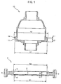
- Fig. 1 is an exploded cross-sectional view illustrating a configuration of parts that are objects to be bonded according to the present embodiment.
- a ring gear 1 and a differential case 10 that are parts of a vehicle are bonded using the bonding method according to the present invention.
- the differential case 10 is a case (differential gear case) for storing a pinion gear and a side gear of a differential mechanism, and corresponds to the second metallic member according to the present invention.
- the differential case 10 is made of cast iron and spheroidal graphitic cast iron such as FCD 450 and FCD 550 is preferable as a specific example thereof.
- the differential case 10 is made of a hollow body extending in an axial direction, and includes a multistage outer circumferential wall section having a plurality of large and small outer diameters. Specifically, a first outer diameter section 11 having an outer diameter of Y1 and a second outer diameter section 12 having an outer diameter of Y2 that is greater than the outer diameter Y1 are formed on the outer circumferential wall section of the differential case 10.
- the ring gear 1 is a gear part which receives a driving force transmitted from a transmission and which corresponds to the first metallic member according to the present invention.
- the ring gear 1 is made of steel and case hardening steel such as SCR 420H is preferable as a specific example thereof.
- the ring gear 1 is made of a ringed member having an opening 2 that penetrates in a thickness direction.
- a gear section 3 that meshes with an output gear of the transmission is formed on an outermost circumferential section of the ring gear 1.
- a first inner diameter section 4 having an inner diameter of X1 and a second inner diameter section 5 having an inner diameter of X2 that is greater than the inner diameter X1 are formed on an inner circumferential wall section of the ring gear 1 that surrounds the opening 2.
- the relationships between the inner diameters X1 and X2 of the ring gear 1 and the outer diameters Y1 and Y2 of the differential case 10 are such that the outer diameter Y1 of the first outer diameter section 11 is slightly greater than the inner diameter X1 of the first inner diameter section 4 and the outer diameter Y2 of the second outer diameter section 12 is slightly greater than the inner diameter X2 of the second inner diameter section 5.
- differences (tightening margins) between the radii of the respective outer diameter sections 11 and 12 and the radii of the respective inner diameter sections 4 and 5 are both set to S.
- the first inner diameter section 4 of the ring gear 1 and the second outer diameter section 12 of the differential case 10 both have axial lengths of L1
- the second inner diameter section 5 of the ring gear 1 and the first outer diameter section 11 of the differential case 10 both have axial lengths of L2, where L1 ⁇ L2.
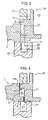
- Fig. 2 is a diagram illustrating a basic configuration of a bonding apparatus 20 used when bonding the ring gear 1 and the differential case 10.
- the bonding apparatus 20 includes an upper electrode 21 and a lower electrode 22, a pressurizing mechanism (not shown) that pressurizes the respective electrodes 21 and 22 in an axial direction (an upward-downward direction in Fig. 2 ), and a power unit 23 that supplies a high current for bonding to the respective electrodes 21 and 22.
- Bonding using the bonding apparatus 20 as described above is performed by energizing the ring gear 1 and the differential case 10 with the upper electrode 21 and the lower electrode 22 while pressurizing the members 1 and 10 in the axial direction, in a state where the differential case 10 is inserted into the opening 2 of the ring gear 1 to be temporarily fixed.
- Fig. 2 illustrates a case where the upper electrode 21 and the lower electrode 22 are vertically arranged so as to oppose each other and the ring gear 1 and the differential case 10 are sandwiched between the upper electrode 21 and the lower electrode 22 to be bonded, for example, it is obvious that bonding can also be performed in a state where the electrodes 21 and 22 are horizontally arranged so as to oppose each other.
- the differential case 10 is inserted downward into the opening 2 of the ring gear 1.
- the ring gear 1 is placed on the lower electrode 22 in a posture where the first inner diameter section 4 is positioned lower than the second inner diameter section 5, and the differential case 10 is inserted downward from above the ring gear 1.
- the first outer diameter section 11 of the differential case 10 is set lower than the second outer diameter section 12 and the first outer diameter section 11 is inserted first into the ring gear 1.
- Fig. 3 is an enlarged view of section A in Fig. 2 and illustrates a state where the aforementioned insertion operation of the differential case 10 has been completed.
- the respective outer diameters Y1, Y2 of the first outer diameter section 11 and the second outer diameter section 12 of the differential case 10 are greater than the respective inner diameters X1, X2 of the first inner diameter section 4 and the second inner diameter section 5 of the ring gear 1 by precisely the tightening margin S, as illustrated in Fig. 3 , when the differential case 10 is inserted into the ring gear 1, an outermost circumferential part of the first outer diameter section 11 abuts the first inner diameter section 4 and an outermost circumferential part of the second outer diameter section 12 abuts the second inner diameter section 5.
- the first inner diameter section 4 and the first outer diameter section 11 as well as the second inner diameter section 5 and the second outer diameter section 12 respectively abut each other at the same time.
- corners of the respective inner diameter sections 4, 5 and the respective outer diameter sections 11, 12 are chamfered and the chamfered parts are to abut each other. In this manner, the differential case 10 is temporarily fixed on the ring gear 1.
- the ring gear 1 and the differential case 10 are sandwiched from above and below and pressurized by the upper electrode 21 and the lower electrode 22, and a voltage for bonding is applied to both electrodes 21 and 22.
- the upper electrode 21 approaches the ring gear 1 and the differential case 10 which are temporarily fixed on the lower electrode 22 from above, a lower end of the upper electrode 21 abuts an upper surface of the second outer diameter section 12 of the differential case 10 and, in this state, a predetermined pressurizing force is applied to both electrodes 21 and 22 in an approaching direction (axial direction).
- a bonding voltage is applied to both electrodes 21 and 22.
- a large current instantaneously flows between the electrodes 21 and 22 via the ring gear 1 and the differential case 10.
- the ring gear 1 and the differential case 10 are in contact with each other via two points, namely, an abutting part of the first inner diameter section 4 and the first outer diameter section 11 and an abutting part of the second inner diameter section 5 and the second outer diameter section 12, the aforementioned current is to flow via the two abutting parts.
- the differential case 10 is pushed downward until the differential case 10 abuts the lower electrode 22, and in a state illustrated in Fig. 4 where the entire inner circumferential surface of the first inner diameter section 4 of the ring gear 1 comes into contact with the outer circumferential surface of the first outer diameter section 11 of the differential case 10 and the entire outer circumferential surface of the second outer diameter section 12 of the differential case 10 comes into contact with the inner circumferential surface of the second inner diameter section 5 of the ring gear 1, energization between the electrodes 21 and 22 is suspended to resolidify the metals on the respective contact surfaces, thereby forming two junctions P1 and P2 as illustrated in Fig. 4 .
- metal softening and plastic flow that occur at the respective contact surfaces between the first inner diameter section 4 and the first outer diameter section 11 and between the second inner diameter section 5 and the second outer diameter section 12 removes oxide film, foreign objects and the like, and by suspending energization in this state, newly-formed surfaces of the metals are metallurgically bonded to each other and resolidified. Accordingly, the first junction P1 is formed between the first inner diameter section 4 and the first outer diameter section 11 and the second junction P2 is formed between the second inner diameter section 5 and the second outer diameter section 12.
- reference characters Q1 and Q2 in Fig. 4 denote burrs formed by metal pushed out, by the amount of the tightening margin S, from between the first inner diameter section 4 and the first outer diameter section 11 and from between the second inner diameter section 5 and the second outer diameter section 12.
- first junction P1 and the second junction P2 formed in this case form a gap 15 therebetween in which the metals do not come contact with each other.
- first and second inner diameter sections 4 and 5 of the ring gear 1 and the first and second outer diameter sections 11 and 12 of the differential case 10 are in a dimensional relationship illustrated in Fig.
- the first inner diameter section 4 with an inner diameter of X1 and the second inner diameter section 5 with an inner diameter of X2 that is greater than the inner diameter of X1 are formed on the inner circumferential wall section of the ring gear 1, and the first outer diameter section 11 and the second outer diameter section 12 respectively having outer diameters Y1 and Y2 that are respectively greater than the inner diameters X1 and X2 by precisely the tightening margin S are formed on the outer circumferential wall section of the differential case 10.
- the joint strength can be increased by forming a single junction with a long junction length without dividing the junction into two parts (PI and P2) as is the case with the embodiment described above.
- PI and P2 two parts
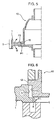
- a modulus of section of the junctions increases in comparison to a case where, for example, the respective junctions P1 and P2 are continuously arranged in the axial direction. Therefore, in particular, when a bending moment M such as illustrated in Fig. 5 is applied on the ring gear 1, a force acting on the junctions P1 and P2 is reduced and bending rigidity is further enhanced. Moreover, since the ring gear 1 receives forces from various directions due to a driving force transferred to the gear section 3 of the ring gear 1, the reliability of the differential mechanism can be further increased by improving bending rigidity as described above.
- the abutting timings of the two locations need not necessarily be precisely the same and a moderate difference in timings may exist.
- a difference arises between the timing where the first inner diameter section 4 abuts the first outer diameter section 11 and the timing where the second inner diameter section 5 abuts the second outer diameter section 12.
- the dimensional difference ⁇ L is small as illustrated in Fig. 6 , the difference in abutting timings is also small and bonding can conceivably be performed without incidence.
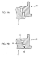
- Figs. 7A and 7B are diagrams describing a case where three junctions (P1, P2, and P3) have been arranged, wherein Fig. 7A illustrates a state before bonding and Fig. 7B illustrates a state after bonding.
- the bonding method according to the present invention is naturally applicable to other metal parts made of materials not limited to steel and cast iron. Since the bonding method according to the present invention involves bonding by metal softening and plastic flow, there are less constraints on materials compared to fusion bonding such as arc welding and laser welding and the bonding method can potentially be applied to various materials.
- the bonding method according to the present invention is a method of bonding metalic members, by which a first metallic member including an opening and a second metallic member including an outer circumferential wall section capable of coming into partial contact with an inner circumferential wall section of the first metallic member that surrounds the opening are bonded to each other by resistance heating through energization while applying pressure in an axial direction of the metallic members.
- the method includes: forming a first inner diameter section having a predetermined inner diameter and a second inner diameter section having an inner diameter that is greater than the inner diameter of the first inner diameter section on the inner circumferential wall section of the first metallic member; and then forming a first outer diameter section and a second outer diameter section having outer diameters that are greater than the inner diameters of the first inner diameter section and the second inner diameter section respectively by a predetermined amount on the outer circumferential wall section of the second metallic member.
- the first and second outer diameter sections of the second metallic member are abutted respectively against the first and second inner diameter sections of the first metallic member, and the first metallic member and the second metallic member are energized by a pair of electrodes while pressurizing both metallic members in an axial direction thereof.
- a first junction where the first inner diameter section and the first outer diameter section are bonded and a second junction where the second inner diameter section and the second outer diameter section are bonded are formed between both metallic members, and a gap is further formed in which the metals do not come into contact with each other between both junctions over a predetermined axial length.
- the first inner diameter section and the first outer diameter section, and the second inner diameter section and the second outer diameter section are simultaneously abutted to each other and energization by the electrodes is started in this state.
- the metallic bonded body according to the present invention is a metallic bonded body, in which a first metallic member including an opening and a second metallic member including an outer circumferential wall section capable of coming into partial contact with an inner circumferential wall section of the first metallic member that surrounds the opening are bonded to each other by resistance heating through energization while applying pressure in an axial direction of the metallic members.
- a first inner diameter section having a predetermined inner diameter and a second inner diameter section having an inner diameter that is greater than the inner diameter of the first inner diameter section are formed on the inner circumferential wall section of the first metallic member, a first outer diameter section and a second outer diameter section having outer diameters that are greater than the inner diameters of the first inner diameter section and the second inner diameter section respectively by a predetermined amount prior to bonding are formed on the outer circumferential wall section of the second metallic member.
- a first junction where the first inner diameter section and the first outer diameter section are bonded and a second junction where the second inner diameter section and the second outer diameter section are bonded are formed between the first metallic member and the second metallic member, and a gap in which the metals do not come into contact with each other is formed between both junctions over a predetermined axial length.
- first and second metallic members by bonding together the first and second metallic members via two junctions (first and second junctions) that are separated from each other in an axial direction, an advantage is achieved in that, in particular, rigidity to bending is effectively improved.
- a preferable application includes a ring gear as the first metallic member and a differential case as the second metallic member.
- an advantage is achieved in that the ring gear and the differential case (differential gear case) can be bonded by high strength and the reliability of a differential mechanism can be further enhanced.
Landscapes
- Engineering & Computer Science (AREA)
- Mechanical Engineering (AREA)
- Retarders (AREA)
- Gears, Cams (AREA)
- Pressure Welding/Diffusion-Bonding (AREA)
Claims (4)
- Verfahren zum Verbinden von Metallelementen, durch das ein erstes metallisches Element (1), das eine Öffnung (2) beinhaltet, und ein zweites metallisches Element (10), das ein Außenumfangswandstück beinhaltet, das in Teilkontakt mit einem Innenumfangswandstück des ersten metallischen Elementes (11), das die Öffnung (2) umgibt, gelangen kann, miteinander mittels Widerstandserwärmung durch Energetisieren bei gleichzeitiger Druckbeaufschlagung in einer axialen Richtung der metallischen Elemente verbunden werden,
wobei das Verfahren die nachfolgenden Schritte umfasst:Bilden eines ersten Innendurchmesserstückes (4), das einen vorbestimmten Innendurchmesser (X1) aufweist, und eines zweiten Innendurchmesserstückes (5), das einen Innendurchmesser (X2) aufweist, der größer als der Innendurchmesser (X1) des ersten Innendurchmesserstückes (4) ist, an dem Innenumfangswandstück des ersten metallischen Elementes (1);Bilden eines ersten Außendurchmesserstückes (11) und eines zweiten Außendurchmesserstückes (12), die Außendurchmesser (Y1, Y2) aufweisen, die um einen vorbestimmten Betrag größer als die Innendurchmesser (X1, X2) des ersten Innendurchmesserstückes (4) beziehungsweise des zweiten Innendurchmesserstückes (5) sind, an dem Außenumfangswandstück des zweiten metallischen Elementes (10);gekennzeichnet durch die nachfolgenden Schritte:durch bezugsrichtiges Anlegen der ersten und zweiten Außendurchmesserstücke (11, 12) des zweiten metallischen Elementes (10) an den ersten und zweiten Innendurchmesserstücken (4, 5) des ersten metallischen Elementes (1) und Energetisieren des ersten metallischen Elementes (1) und des zweiten metallischen Elementes (10) mittels eines Paares von Elektroden (12, 22) bei gleichzeitiger Druckbeaufschlagung der beiden metallischen Elemente (1, 10) in einer axialen Richtung hiervon erfolgendesBilden einer ersten Verbindungsstelle (P1), an der das erste Innendurchmesserstück (4) und das erste Außendurchmesserstück (11) verbunden sind, und einer zweiten Verbindungsstelle (P2), an der das zweite Innendurchmesserstück (5) und das zweite Außendurchmesserstück (12) verbunden sind, zwischen den beiden metallischen Elementen (1, 10) und des Weiteren Bilden eines Spaltes (15), in dem die Metalle nicht in Kontakt miteinander gelangen, zwischen den beiden Verbindungsstellen (P1, P2) über eine vorbestimmte axiale Länge. - Verfahren zum Verbinden von metallischen Elementen nach Anspruch 1, wobei:zu Beginn des Verbindens des ersten metallischen Elementes (1) und des zweiten metallischen Elementes (10) das erste Innendurchmesserstück (4) und das erste Außendurchmesserstück (11) sowie das zweite Innendurchmesserstück (5) und das zweite Außendurchmesserstück (12) gleichzeitig aneinandergelegt werden und die Energetisierung mittels der Elektroden (21, 22) in diesem Zustand beginnt.
- Metallischer Verbindungskörper, in dem ein erstes metallisches Element (1), das eine Öffnung (2) beinhaltet, und ein zweites metallisches Element (10), das ein Außenumfangswandstück beinhaltet, das in Teilkontakt mit einem Innenumfangswandstück des ersten metallischen Elementes (1), das die Öffnung (2) umgibt, gelangen kann, miteinander mittels Widerstandserwärmung durch Energetisieren bei gleichzeitiger Druckbeaufschlagung in einer axialen Richtung der metallischen Elemente verbunden werden, wobei:ein erstes Innendurchmesserstück (4), das einen vorbestimmten Innendurchmesser (X1) aufweist, und ein zweites Innendurchmesserstück (5), das einen Innendurchmesser (X2) aufweist, der größer als der Innendurchmesser (X1) des ersten Innendurchmesserstückes (5) ist, an dem Innenumfangswandstück des ersten metallischen Elementes (1) gebildet werden,ein erstes Außendurchmesserstück (11) und ein zweites Außendurchmesserstück (12), die Außendurchmesser (Y1, Y2) aufweisen, die um einen vorbestimmten Betrag größer als die Innendurchmesser (X1, X2) des ersten Innendurchmesserstückes (4) beziehungsweise des zweiten Innendurchmesserstückes (5) vor dem Verbinden sind, an dem Außenumfangswandstück des zweiten metallischen Elementes gebildet werden,dadurch gekennzeichnet, dass:eine erste Verbindungsstelle (P1), an der das erste Innendurchmesserstück (4) und das erste Außendurchmesserstück (11) verbunden sind, und eine zweite Verbindungsstelle (P2), an der das zweite Innendurchmesserstück (5) und das zweite Außendurchmesserstück (12) verbunden sind, zwischen dem ersten metallischen Element (1) und dem zweiten metallischen Element (10) gebildet werden und ein Spalt (15), in dem die Metalle nicht in Kontakt miteinander gelangen, zwischen den beiden Verbindungsstellen (P1, P2) über eine vorbestimmte axiale Länge gebildet wird.
- Metallischer Verbindungskörper nach Anspruch 3, wobei das erste metallische Element (1) ein Hohlrad bzw. Zahnkranz ist und das zweite metallische Element (10) ein Ausgleichsgehäuse bzw. Differenzialgehäuse ist.
Applications Claiming Priority (1)
| Application Number | Priority Date | Filing Date | Title |
|---|---|---|---|
| JP2009253185A JP5399206B2 (ja) | 2009-11-04 | 2009-11-04 | 金属部材の接合方法および金属接合体 |
Publications (2)
| Publication Number | Publication Date |
|---|---|
| EP2319652A1 EP2319652A1 (de) | 2011-05-11 |
| EP2319652B1 true EP2319652B1 (de) | 2014-07-16 |
Family
ID=43513870
Family Applications (1)
| Application Number | Title | Priority Date | Filing Date |
|---|---|---|---|
| EP10014202.5A Active EP2319652B1 (de) | 2009-11-04 | 2010-11-02 | Verfahren zur Verbinden metallischer Elemente und gebundener metallischer Körper |
Country Status (4)
| Country | Link |
|---|---|
| US (1) | US8710393B2 (de) |
| EP (1) | EP2319652B1 (de) |
| JP (1) | JP5399206B2 (de) |
| CN (1) | CN102059437B (de) |
Families Citing this family (31)
| Publication number | Priority date | Publication date | Assignee | Title |
|---|---|---|---|---|
| JP5327130B2 (ja) * | 2010-04-23 | 2013-10-30 | トヨタ自動車株式会社 | リングギヤの溶接方法及び溶接構造 |
| DE102011102064A1 (de) * | 2011-05-19 | 2012-11-22 | Trw Airbag Systems Gmbh | Verfahren zur Herstellung eines Gasgenerators |
| US11152657B2 (en) | 2012-04-11 | 2021-10-19 | Ionic Materials, Inc. | Alkaline metal-air battery cathode |
| US11319411B2 (en) | 2012-04-11 | 2022-05-03 | Ionic Materials, Inc. | Solid ionically conducting polymer material |
| US11251455B2 (en) | 2012-04-11 | 2022-02-15 | Ionic Materials, Inc. | Solid ionically conducting polymer material |
| US9819053B1 (en) | 2012-04-11 | 2017-11-14 | Ionic Materials, Inc. | Solid electrolyte high energy battery |
| US12074274B2 (en) | 2012-04-11 | 2024-08-27 | Ionic Materials, Inc. | Solid state bipolar battery |
| US10559827B2 (en) | 2013-12-03 | 2020-02-11 | Ionic Materials, Inc. | Electrochemical cell having solid ionically conducting polymer material |
| KR102353151B1 (ko) | 2013-12-03 | 2022-01-18 | 아이오닉 머터리얼스, 인코퍼레이션 | 이온 전도성 고체 폴리머 물질 및 응용 |
| JP7109879B2 (ja) | 2014-04-01 | 2022-08-01 | イオニツク・マテリアルズ・インコーポレーテツド | 高容量高分子の陰極および該陰極を含む高エネルギー密度の再充電可能な電池 |
| DE102015207176A1 (de) * | 2014-06-23 | 2015-12-24 | Zf Friedrichshafen Ag | Verfahren zur Herstellung eines Fahrwerkbauteils |
| JP5990343B2 (ja) * | 2014-08-18 | 2016-09-14 | オリジン電気株式会社 | 金属接合体及び金属接合体の製造方法 |
| KR101814354B1 (ko) * | 2014-10-10 | 2018-01-30 | 오리진 일렉트릭 캄파니 리미티드 | 전기접합방법 및 전기접합장치 |
| DE102015205628A1 (de) * | 2015-03-27 | 2016-09-29 | Zf Friedrichshafen Ag | Verfahren zur Herstellung einer Fahrwerkbaugruppe und Fahrwerkbaugruppe hergestellt nach einem solchen Verfahren |
| CN108352565A (zh) | 2015-06-04 | 2018-07-31 | 离子材料公司 | 具有固体聚合物电解质的锂金属电池 |
| CN108140805B (zh) | 2015-06-04 | 2022-03-01 | 离子材料公司 | 固态双极性电池 |
| US11342559B2 (en) | 2015-06-08 | 2022-05-24 | Ionic Materials, Inc. | Battery with polyvalent metal anode |
| SG10201911155XA (en) | 2015-06-08 | 2020-01-30 | Ionic Materials Inc | Battery having aluminum anode and solid polymer electrolyte |
| JP2017064773A (ja) * | 2015-10-01 | 2017-04-06 | 株式会社清水製作所 | 二つの部材の溶接方法、およびその方法によって溶接された接合部材 |
| JP6607124B2 (ja) * | 2016-03-31 | 2019-11-20 | アイシン・エィ・ダブリュ株式会社 | 差動装置の部材接合構造 |
| DE102016213451A1 (de) * | 2016-05-19 | 2017-11-23 | Robert Bosch Gmbh | Kraftstoff-Hochdruckpumpe |
| JP6109395B1 (ja) * | 2016-10-18 | 2017-04-05 | 株式会社エフ・シー・シー | 結合部品の製造方法 |
| EP3574542A4 (de) | 2017-01-26 | 2020-09-02 | Ionic Materials, Inc. | Alkalische batteriekathode mit festpolymerelektrolyt |
| US10744556B2 (en) | 2017-12-21 | 2020-08-18 | American Axle & Manufacturing, Inc. | Method for forming a toothed article |
| JP6643759B2 (ja) * | 2018-03-23 | 2020-02-12 | 株式会社オリジン | 嵌合部材、環状部材、接合済部材及び接合済部材の製造方法 |
| DE102018220105B4 (de) * | 2018-11-22 | 2021-01-21 | Audi Ag | Differentialgetriebe für ein Kraftfahrzeug mit einem durch zwei Presspassungen am Gehäuse aufgepressten Abtriebsrad |
| JP7405523B2 (ja) * | 2019-06-28 | 2023-12-26 | 武蔵精密工業株式会社 | 伝動装置 |
| JP2021016862A (ja) * | 2019-07-17 | 2021-02-15 | マツダ株式会社 | 金属部材の接合方法及び接合構造 |
| CN112647245B (zh) * | 2019-10-10 | 2025-01-10 | 青岛海尔洗衣机有限公司 | 微气泡喷头及具有该微气泡喷头的洗涤设备 |
| JP6868733B1 (ja) * | 2020-06-02 | 2021-05-12 | 株式会社オリジン | 接合物品の製造方法及び製造装置 |
| JP6882581B1 (ja) * | 2020-06-02 | 2021-06-02 | 株式会社オリジン | 接合物品の製造方法及び製造装置 |
Family Cites Families (9)
| Publication number | Priority date | Publication date | Assignee | Title |
|---|---|---|---|---|
| JP2536200B2 (ja) * | 1989-12-11 | 1996-09-18 | 三菱マテリアル株式会社 | 金属焼結材の接合方法と、金属焼結材製プ―リおよびその製造方法 |
| JPH06218560A (ja) * | 1993-01-21 | 1994-08-09 | Toyota Motor Corp | シリンダブロックの製造方法 |
| JP2004017048A (ja) | 2002-06-12 | 2004-01-22 | Origin Electric Co Ltd | リングマッシュ溶接方法及び装置 |
| US6717091B2 (en) * | 2002-08-22 | 2004-04-06 | Delphi Technologies, Inc. | Method for metallurgically attaching together two tubes |
| US20040056001A1 (en) * | 2002-09-24 | 2004-03-25 | Delphi Technologies Inc. | Deformation resistance welding of sheet metal, tubes, and similar shapes |
| JP4397631B2 (ja) * | 2003-06-27 | 2010-01-13 | 株式会社オーハシテクニカ | 圧入接合構造及びその接合部品 |
| JP2005081351A (ja) * | 2003-09-04 | 2005-03-31 | Aisin Aw Co Ltd | 摩擦圧接部材およびこれを備えた差動装置 |
| US8202628B2 (en) | 2006-12-08 | 2012-06-19 | Musashi Seimitsu Kogyo Kabushiki Kaisha | Fusion-bonded product having high-strength part and manufacturing method thereof |
| JP4343989B1 (ja) | 2008-04-10 | 2009-10-14 | 株式会社新川 | ボンディング装置およびボンディング装置に用いられるボンディング領域の位置認識方法及びプログラム |
-
2009
- 2009-11-04 JP JP2009253185A patent/JP5399206B2/ja active Active
-
2010
- 2010-10-28 US US12/914,473 patent/US8710393B2/en active Active
- 2010-11-02 EP EP10014202.5A patent/EP2319652B1/de active Active
- 2010-11-04 CN CN201010544017.5A patent/CN102059437B/zh active Active
Also Published As
| Publication number | Publication date |
|---|---|
| JP2011098358A (ja) | 2011-05-19 |
| US8710393B2 (en) | 2014-04-29 |
| CN102059437A (zh) | 2011-05-18 |
| US20110104511A1 (en) | 2011-05-05 |
| JP5399206B2 (ja) | 2014-01-29 |
| CN102059437B (zh) | 2015-09-02 |
| EP2319652A1 (de) | 2011-05-11 |
Similar Documents
| Publication | Publication Date | Title |
|---|---|---|
| US8710393B2 (en) | Method of bonding metallic members, and metallic bonded body | |
| JP5512395B2 (ja) | 金属部材の接合方法 | |
| CN103038017B (zh) | 通过焊接电流和压入对轴和轮毂进行连接的方法以及轴和轮毂通过这种连接构成的装置 | |
| CN102131611B (zh) | 液相扩散接合管接头及其制造方法 | |
| JP2012507645A (ja) | 補強材 | |
| US11161196B2 (en) | Metallic member bonding device for pressing rod-shaped or cylindrical first metallic member into hole portion of annular second metallic member to bond the same and bonding method therefor | |
| WO2016027650A1 (ja) | 金属接合体及び金属接合体の製造方法 | |
| JP2008221321A (ja) | 摩擦点接合方法 | |
| CN109996635A (zh) | 具有接合辅助元件的构件、至少两个构件的构件组合体以及用于制造的方法 | |
| JP2011056531A (ja) | ピストンロッドの製造方法 | |
| JP6328367B2 (ja) | プロペラシャフトの製造方法及びプロペラシャフト | |
| CN114080292A (zh) | 金属部件的接合方法及接合构造 | |
| JP2009000712A (ja) | 金属部材の接合方法およびその接合構造 | |
| JP4453506B2 (ja) | 摩擦点接合方法 | |
| JP6868733B1 (ja) | 接合物品の製造方法及び製造装置 | |
| CN103398057B (zh) | 钢管对接结构及具有其的起重机 | |
| JP2013226562A (ja) | 溶接継手 | |
| JP7265282B2 (ja) | 摩擦圧接装置および摩擦圧接方法 | |
| EP3768462A1 (de) | Überlappungsschweissen mit gestaltetem spalt für erhöhte verbindungsfestigkeit | |
| WO2021131988A1 (ja) | スポット溶接方法 | |
| JPH11309586A (ja) | 金属管の接合方法及びその方法において用いられる金属円筒継手 | |
| JP2026035063A (ja) | 接合品の製造方法 | |
| JP2021102229A (ja) | スポット溶接方法 | |
| JP2010174563A (ja) | 定着金具を備えた鉄筋および鉄筋の製造方法 | |
| JP2011224604A (ja) | 高剛性かつ軽量なプロペラシャフトの製造方法 |
Legal Events
| Date | Code | Title | Description |
|---|---|---|---|
| PUAI | Public reference made under article 153(3) epc to a published international application that has entered the european phase |
Free format text: ORIGINAL CODE: 0009012 |
|
| AK | Designated contracting states |
Kind code of ref document: A1 Designated state(s): AL AT BE BG CH CY CZ DE DK EE ES FI FR GB GR HR HU IE IS IT LI LT LU LV MC MK MT NL NO PL PT RO RS SE SI SK SM TR |
|
| AX | Request for extension of the european patent |
Extension state: BA ME |
|
| RIN1 | Information on inventor provided before grant (corrected) |
Inventor name: HAMANO, MASATOSHI Inventor name: SAWAZAKI, TOMOO Inventor name: YAMAGATA, AKINOBU Inventor name: OKUMURA, SHINYA Inventor name: HASHIMOTO, AKIRA Inventor name: SASAKI, HIROJI Inventor name: HAYASHI, HIROAKI Inventor name: SHIINO, KAZUYUKI Inventor name: ISHIDA, KAZUYUKI Inventor name: FUJII, TAKESHI |
|
| 17P | Request for examination filed |
Effective date: 20110728 |
|
| GRAP | Despatch of communication of intention to grant a patent |
Free format text: ORIGINAL CODE: EPIDOSNIGR1 |
|
| RIC1 | Information provided on ipc code assigned before grant |
Ipc: B23K 11/093 20060101AFI20140123BHEP Ipc: B23K 33/00 20060101ALI20140123BHEP |
|
| INTG | Intention to grant announced |
Effective date: 20140207 |
|
| GRAS | Grant fee paid |
Free format text: ORIGINAL CODE: EPIDOSNIGR3 |
|
| GRAA | (expected) grant |
Free format text: ORIGINAL CODE: 0009210 |
|
| AK | Designated contracting states |
Kind code of ref document: B1 Designated state(s): AL AT BE BG CH CY CZ DE DK EE ES FI FR GB GR HR HU IE IS IT LI LT LU LV MC MK MT NL NO PL PT RO RS SE SI SK SM TR |
|
| REG | Reference to a national code |
Ref country code: GB Ref legal event code: FG4D |
|
| REG | Reference to a national code |
Ref country code: CH Ref legal event code: EP |
|
| REG | Reference to a national code |
Ref country code: IE Ref legal event code: FG4D |
|
| REG | Reference to a national code |
Ref country code: AT Ref legal event code: REF Ref document number: 677287 Country of ref document: AT Kind code of ref document: T Effective date: 20140815 |
|
| REG | Reference to a national code |
Ref country code: DE Ref legal event code: R096 Ref document number: 602010017421 Country of ref document: DE Effective date: 20140828 |
|
| REG | Reference to a national code |
Ref country code: FR Ref legal event code: TP Owner name: ORIGIN ELECTRIC COMPANY, LTD., JP Effective date: 20140916 |
|
| REG | Reference to a national code |
Ref country code: NL Ref legal event code: VDEP Effective date: 20140716 |
|
| REG | Reference to a national code |
Ref country code: AT Ref legal event code: MK05 Ref document number: 677287 Country of ref document: AT Kind code of ref document: T Effective date: 20140716 |
|
| REG | Reference to a national code |
Ref country code: LT Ref legal event code: MG4D |
|
| PG25 | Lapsed in a contracting state [announced via postgrant information from national office to epo] |
Ref country code: NO Free format text: LAPSE BECAUSE OF FAILURE TO SUBMIT A TRANSLATION OF THE DESCRIPTION OR TO PAY THE FEE WITHIN THE PRESCRIBED TIME-LIMIT Effective date: 20141016 Ref country code: GR Free format text: LAPSE BECAUSE OF FAILURE TO SUBMIT A TRANSLATION OF THE DESCRIPTION OR TO PAY THE FEE WITHIN THE PRESCRIBED TIME-LIMIT Effective date: 20141017 Ref country code: BG Free format text: LAPSE BECAUSE OF FAILURE TO SUBMIT A TRANSLATION OF THE DESCRIPTION OR TO PAY THE FEE WITHIN THE PRESCRIBED TIME-LIMIT Effective date: 20141016 Ref country code: LT Free format text: LAPSE BECAUSE OF FAILURE TO SUBMIT A TRANSLATION OF THE DESCRIPTION OR TO PAY THE FEE WITHIN THE PRESCRIBED TIME-LIMIT Effective date: 20140716 Ref country code: ES Free format text: LAPSE BECAUSE OF FAILURE TO SUBMIT A TRANSLATION OF THE DESCRIPTION OR TO PAY THE FEE WITHIN THE PRESCRIBED TIME-LIMIT Effective date: 20140716 Ref country code: SE Free format text: LAPSE BECAUSE OF FAILURE TO SUBMIT A TRANSLATION OF THE DESCRIPTION OR TO PAY THE FEE WITHIN THE PRESCRIBED TIME-LIMIT Effective date: 20140716 Ref country code: PT Free format text: LAPSE BECAUSE OF FAILURE TO SUBMIT A TRANSLATION OF THE DESCRIPTION OR TO PAY THE FEE WITHIN THE PRESCRIBED TIME-LIMIT Effective date: 20141117 Ref country code: FI Free format text: LAPSE BECAUSE OF FAILURE TO SUBMIT A TRANSLATION OF THE DESCRIPTION OR TO PAY THE FEE WITHIN THE PRESCRIBED TIME-LIMIT Effective date: 20140716 |
|
| PG25 | Lapsed in a contracting state [announced via postgrant information from national office to epo] |
Ref country code: RS Free format text: LAPSE BECAUSE OF FAILURE TO SUBMIT A TRANSLATION OF THE DESCRIPTION OR TO PAY THE FEE WITHIN THE PRESCRIBED TIME-LIMIT Effective date: 20140716 Ref country code: CY Free format text: LAPSE BECAUSE OF FAILURE TO SUBMIT A TRANSLATION OF THE DESCRIPTION OR TO PAY THE FEE WITHIN THE PRESCRIBED TIME-LIMIT Effective date: 20140716 Ref country code: PL Free format text: LAPSE BECAUSE OF FAILURE TO SUBMIT A TRANSLATION OF THE DESCRIPTION OR TO PAY THE FEE WITHIN THE PRESCRIBED TIME-LIMIT Effective date: 20140716 Ref country code: IS Free format text: LAPSE BECAUSE OF FAILURE TO SUBMIT A TRANSLATION OF THE DESCRIPTION OR TO PAY THE FEE WITHIN THE PRESCRIBED TIME-LIMIT Effective date: 20141116 Ref country code: AT Free format text: LAPSE BECAUSE OF FAILURE TO SUBMIT A TRANSLATION OF THE DESCRIPTION OR TO PAY THE FEE WITHIN THE PRESCRIBED TIME-LIMIT Effective date: 20140716 Ref country code: NL Free format text: LAPSE BECAUSE OF FAILURE TO SUBMIT A TRANSLATION OF THE DESCRIPTION OR TO PAY THE FEE WITHIN THE PRESCRIBED TIME-LIMIT Effective date: 20140716 Ref country code: LV Free format text: LAPSE BECAUSE OF FAILURE TO SUBMIT A TRANSLATION OF THE DESCRIPTION OR TO PAY THE FEE WITHIN THE PRESCRIBED TIME-LIMIT Effective date: 20140716 |
|
| REG | Reference to a national code |
Ref country code: DE Ref legal event code: R097 Ref document number: 602010017421 Country of ref document: DE |
|
| PG25 | Lapsed in a contracting state [announced via postgrant information from national office to epo] |
Ref country code: CZ Free format text: LAPSE BECAUSE OF FAILURE TO SUBMIT A TRANSLATION OF THE DESCRIPTION OR TO PAY THE FEE WITHIN THE PRESCRIBED TIME-LIMIT Effective date: 20140716 Ref country code: SK Free format text: LAPSE BECAUSE OF FAILURE TO SUBMIT A TRANSLATION OF THE DESCRIPTION OR TO PAY THE FEE WITHIN THE PRESCRIBED TIME-LIMIT Effective date: 20140716 Ref country code: EE Free format text: LAPSE BECAUSE OF FAILURE TO SUBMIT A TRANSLATION OF THE DESCRIPTION OR TO PAY THE FEE WITHIN THE PRESCRIBED TIME-LIMIT Effective date: 20140716 Ref country code: RO Free format text: LAPSE BECAUSE OF FAILURE TO SUBMIT A TRANSLATION OF THE DESCRIPTION OR TO PAY THE FEE WITHIN THE PRESCRIBED TIME-LIMIT Effective date: 20140716 Ref country code: DK Free format text: LAPSE BECAUSE OF FAILURE TO SUBMIT A TRANSLATION OF THE DESCRIPTION OR TO PAY THE FEE WITHIN THE PRESCRIBED TIME-LIMIT Effective date: 20140716 Ref country code: IT Free format text: LAPSE BECAUSE OF FAILURE TO SUBMIT A TRANSLATION OF THE DESCRIPTION OR TO PAY THE FEE WITHIN THE PRESCRIBED TIME-LIMIT Effective date: 20140716 |
|
| PLBE | No opposition filed within time limit |
Free format text: ORIGINAL CODE: 0009261 |
|
| STAA | Information on the status of an ep patent application or granted ep patent |
Free format text: STATUS: NO OPPOSITION FILED WITHIN TIME LIMIT |
|
| 26N | No opposition filed |
Effective date: 20150417 |
|
| PG25 | Lapsed in a contracting state [announced via postgrant information from national office to epo] |
Ref country code: MC Free format text: LAPSE BECAUSE OF FAILURE TO SUBMIT A TRANSLATION OF THE DESCRIPTION OR TO PAY THE FEE WITHIN THE PRESCRIBED TIME-LIMIT Effective date: 20140716 Ref country code: LU Free format text: LAPSE BECAUSE OF FAILURE TO SUBMIT A TRANSLATION OF THE DESCRIPTION OR TO PAY THE FEE WITHIN THE PRESCRIBED TIME-LIMIT Effective date: 20141102 Ref country code: BE Free format text: LAPSE BECAUSE OF NON-PAYMENT OF DUE FEES Effective date: 20141130 |
|
| REG | Reference to a national code |
Ref country code: CH Ref legal event code: PL |
|
| GBPC | Gb: european patent ceased through non-payment of renewal fee |
Effective date: 20141102 |
|
| PG25 | Lapsed in a contracting state [announced via postgrant information from national office to epo] |
Ref country code: LI Free format text: LAPSE BECAUSE OF NON-PAYMENT OF DUE FEES Effective date: 20141130 Ref country code: CH Free format text: LAPSE BECAUSE OF NON-PAYMENT OF DUE FEES Effective date: 20141130 |
|
| REG | Reference to a national code |
Ref country code: IE Ref legal event code: MM4A |
|
| PG25 | Lapsed in a contracting state [announced via postgrant information from national office to epo] |
Ref country code: IE Free format text: LAPSE BECAUSE OF NON-PAYMENT OF DUE FEES Effective date: 20141102 Ref country code: GB Free format text: LAPSE BECAUSE OF NON-PAYMENT OF DUE FEES Effective date: 20141102 |
|
| REG | Reference to a national code |
Ref country code: FR Ref legal event code: PLFP Year of fee payment: 6 |
|
| PG25 | Lapsed in a contracting state [announced via postgrant information from national office to epo] |
Ref country code: SI Free format text: LAPSE BECAUSE OF FAILURE TO SUBMIT A TRANSLATION OF THE DESCRIPTION OR TO PAY THE FEE WITHIN THE PRESCRIBED TIME-LIMIT Effective date: 20140716 |
|
| PG25 | Lapsed in a contracting state [announced via postgrant information from national office to epo] |
Ref country code: SM Free format text: LAPSE BECAUSE OF FAILURE TO SUBMIT A TRANSLATION OF THE DESCRIPTION OR TO PAY THE FEE WITHIN THE PRESCRIBED TIME-LIMIT Effective date: 20140716 |
|
| REG | Reference to a national code |
Ref country code: DE Ref legal event code: R081 Ref document number: 602010017421 Country of ref document: DE Owner name: ORIGIN COMPANY, LIMITED, SAITAMA-SHI, JP Free format text: FORMER OWNERS: MAZDA MOTOR CORP., HIROSHIMA, JP; ORIGIN ELECTRIC CO. LTD., TOKYO, JP Ref country code: DE Ref legal event code: R082 Ref document number: 602010017421 Country of ref document: DE Representative=s name: MUELLER-BORE & PARTNER PATENTANWAELTE PARTG MB, DE Ref country code: DE Ref legal event code: R081 Ref document number: 602010017421 Country of ref document: DE Owner name: ORIGIN ELECTRIC CO. LTD., SAITAMA-SHI, JP Free format text: FORMER OWNERS: MAZDA MOTOR CORP., HIROSHIMA, JP; ORIGIN ELECTRIC CO. LTD., TOKYO, JP Ref country code: DE Ref legal event code: R081 Ref document number: 602010017421 Country of ref document: DE Owner name: MAZDA MOTOR CORP., JP Free format text: FORMER OWNERS: MAZDA MOTOR CORP., HIROSHIMA, JP; ORIGIN ELECTRIC CO. LTD., TOKYO, JP |
|
| PG25 | Lapsed in a contracting state [announced via postgrant information from national office to epo] |
Ref country code: TR Free format text: LAPSE BECAUSE OF FAILURE TO SUBMIT A TRANSLATION OF THE DESCRIPTION OR TO PAY THE FEE WITHIN THE PRESCRIBED TIME-LIMIT Effective date: 20140716 Ref country code: HU Free format text: LAPSE BECAUSE OF FAILURE TO SUBMIT A TRANSLATION OF THE DESCRIPTION OR TO PAY THE FEE WITHIN THE PRESCRIBED TIME-LIMIT; INVALID AB INITIO Effective date: 20101102 Ref country code: HR Free format text: LAPSE BECAUSE OF FAILURE TO SUBMIT A TRANSLATION OF THE DESCRIPTION OR TO PAY THE FEE WITHIN THE PRESCRIBED TIME-LIMIT Effective date: 20140716 Ref country code: MT Free format text: LAPSE BECAUSE OF FAILURE TO SUBMIT A TRANSLATION OF THE DESCRIPTION OR TO PAY THE FEE WITHIN THE PRESCRIBED TIME-LIMIT Effective date: 20140716 Ref country code: BE Free format text: LAPSE BECAUSE OF FAILURE TO SUBMIT A TRANSLATION OF THE DESCRIPTION OR TO PAY THE FEE WITHIN THE PRESCRIBED TIME-LIMIT Effective date: 20140716 |
|
| REG | Reference to a national code |
Ref country code: FR Ref legal event code: CA Effective date: 20160719 |
|
| REG | Reference to a national code |
Ref country code: FR Ref legal event code: PLFP Year of fee payment: 7 |
|
| REG | Reference to a national code |
Ref country code: FR Ref legal event code: PLFP Year of fee payment: 8 |
|
| PG25 | Lapsed in a contracting state [announced via postgrant information from national office to epo] |
Ref country code: MK Free format text: LAPSE BECAUSE OF FAILURE TO SUBMIT A TRANSLATION OF THE DESCRIPTION OR TO PAY THE FEE WITHIN THE PRESCRIBED TIME-LIMIT Effective date: 20140716 |
|
| PG25 | Lapsed in a contracting state [announced via postgrant information from national office to epo] |
Ref country code: AL Free format text: LAPSE BECAUSE OF FAILURE TO SUBMIT A TRANSLATION OF THE DESCRIPTION OR TO PAY THE FEE WITHIN THE PRESCRIBED TIME-LIMIT Effective date: 20140716 |
|
| REG | Reference to a national code |
Ref country code: DE Ref legal event code: R082 Ref document number: 602010017421 Country of ref document: DE Representative=s name: MUELLER-BORE & PARTNER PATENTANWAELTE PARTG MB, DE Ref country code: DE Ref legal event code: R081 Ref document number: 602010017421 Country of ref document: DE Owner name: ORIGIN COMPANY, LIMITED, SAITAMA-SHI, JP Free format text: FORMER OWNERS: MAZDA MOTOR CORP., HIROSHIMA, JP; ORIGIN ELECTRIC CO. LTD., SAITAMA-SHI, SAITAMA, JP |
|
| PGFP | Annual fee paid to national office [announced via postgrant information from national office to epo] |
Ref country code: DE Payment date: 20241001 Year of fee payment: 15 |
|
| PGFP | Annual fee paid to national office [announced via postgrant information from national office to epo] |
Ref country code: FR Payment date: 20241128 Year of fee payment: 15 |