EP2318599B1 - Soupape d'admission d'air - Google Patents
Soupape d'admission d'air Download PDFInfo
- Publication number
- EP2318599B1 EP2318599B1 EP09786103.3A EP09786103A EP2318599B1 EP 2318599 B1 EP2318599 B1 EP 2318599B1 EP 09786103 A EP09786103 A EP 09786103A EP 2318599 B1 EP2318599 B1 EP 2318599B1
- Authority
- EP
- European Patent Office
- Prior art keywords
- main body
- lid
- sealing element
- valve
- air admittance
- Prior art date
- Legal status (The legal status is an assumption and is not a legal conclusion. Google has not performed a legal analysis and makes no representation as to the accuracy of the status listed.)
- Active
Links
- 238000004891 communication Methods 0.000 claims description 80
- 238000007789 sealing Methods 0.000 claims description 71
- 230000000903 blocking effect Effects 0.000 claims description 2
- 239000000463 material Substances 0.000 description 14
- 239000002351 wastewater Substances 0.000 description 7
- 238000009428 plumbing Methods 0.000 description 5
- 238000004519 manufacturing process Methods 0.000 description 4
- 238000013461 design Methods 0.000 description 3
- 239000004676 acrylonitrile butadiene styrene Substances 0.000 description 2
- 230000008901 benefit Effects 0.000 description 2
- 230000000295 complement effect Effects 0.000 description 2
- 238000010276 construction Methods 0.000 description 2
- -1 for example Substances 0.000 description 2
- 230000005484 gravity Effects 0.000 description 2
- 238000000034 method Methods 0.000 description 2
- 238000012986 modification Methods 0.000 description 2
- 230000004048 modification Effects 0.000 description 2
- 239000004800 polyvinyl chloride Substances 0.000 description 2
- 230000003014 reinforcing effect Effects 0.000 description 2
- 239000012815 thermoplastic material Substances 0.000 description 2
- 238000013022 venting Methods 0.000 description 2
- 230000004075 alteration Effects 0.000 description 1
- 238000011010 flushing procedure Methods 0.000 description 1
- 239000007789 gas Substances 0.000 description 1
- 210000003739 neck Anatomy 0.000 description 1
- 235000019645 odor Nutrition 0.000 description 1
- 230000002093 peripheral effect Effects 0.000 description 1
- 229920001296 polysiloxane Polymers 0.000 description 1
- 239000000126 substance Substances 0.000 description 1
- 238000009423 ventilation Methods 0.000 description 1
Images


Classifications
-
- E—FIXED CONSTRUCTIONS
- E03—WATER SUPPLY; SEWERAGE
- E03C—DOMESTIC PLUMBING INSTALLATIONS FOR FRESH WATER OR WASTE WATER; SINKS
- E03C1/00—Domestic plumbing installations for fresh water or waste water; Sinks
- E03C1/12—Plumbing installations for waste water; Basins or fountains connected thereto; Sinks
- E03C1/122—Pipe-line systems for waste water in building
-
- E—FIXED CONSTRUCTIONS
- E03—WATER SUPPLY; SEWERAGE
- E03C—DOMESTIC PLUMBING INSTALLATIONS FOR FRESH WATER OR WASTE WATER; SINKS
- E03C1/00—Domestic plumbing installations for fresh water or waste water; Sinks
- E03C1/12—Plumbing installations for waste water; Basins or fountains connected thereto; Sinks
- E03C1/122—Pipe-line systems for waste water in building
- E03C1/1222—Arrangements of devices in domestic waste water pipe-line systems
- E03C1/1225—Arrangements of devices in domestic waste water pipe-line systems of air admittance valves
-
- F—MECHANICAL ENGINEERING; LIGHTING; HEATING; WEAPONS; BLASTING
- F16—ENGINEERING ELEMENTS AND UNITS; GENERAL MEASURES FOR PRODUCING AND MAINTAINING EFFECTIVE FUNCTIONING OF MACHINES OR INSTALLATIONS; THERMAL INSULATION IN GENERAL
- F16K—VALVES; TAPS; COCKS; ACTUATING-FLOATS; DEVICES FOR VENTING OR AERATING
- F16K15/00—Check valves
- F16K15/14—Check valves with flexible valve members
-
- F—MECHANICAL ENGINEERING; LIGHTING; HEATING; WEAPONS; BLASTING
- F16—ENGINEERING ELEMENTS AND UNITS; GENERAL MEASURES FOR PRODUCING AND MAINTAINING EFFECTIVE FUNCTIONING OF MACHINES OR INSTALLATIONS; THERMAL INSULATION IN GENERAL
- F16K—VALVES; TAPS; COCKS; ACTUATING-FLOATS; DEVICES FOR VENTING OR AERATING
- F16K24/00—Devices, e.g. valves, for venting or aerating enclosures
- F16K24/06—Devices, e.g. valves, for venting or aerating enclosures for aerating only
-
- Y—GENERAL TAGGING OF NEW TECHNOLOGICAL DEVELOPMENTS; GENERAL TAGGING OF CROSS-SECTIONAL TECHNOLOGIES SPANNING OVER SEVERAL SECTIONS OF THE IPC; TECHNICAL SUBJECTS COVERED BY FORMER USPC CROSS-REFERENCE ART COLLECTIONS [XRACs] AND DIGESTS
- Y10—TECHNICAL SUBJECTS COVERED BY FORMER USPC
- Y10T—TECHNICAL SUBJECTS COVERED BY FORMER US CLASSIFICATION
- Y10T137/00—Fluid handling
- Y10T137/7722—Line condition change responsive valves
- Y10T137/7837—Direct response valves [i.e., check valve type]
- Y10T137/7897—Vacuum relief type
-
- Y—GENERAL TAGGING OF NEW TECHNOLOGICAL DEVELOPMENTS; GENERAL TAGGING OF CROSS-SECTIONAL TECHNOLOGIES SPANNING OVER SEVERAL SECTIONS OF THE IPC; TECHNICAL SUBJECTS COVERED BY FORMER USPC CROSS-REFERENCE ART COLLECTIONS [XRACs] AND DIGESTS
- Y10—TECHNICAL SUBJECTS COVERED BY FORMER USPC
- Y10T—TECHNICAL SUBJECTS COVERED BY FORMER US CLASSIFICATION
- Y10T137/00—Fluid handling
- Y10T137/7722—Line condition change responsive valves
- Y10T137/7837—Direct response valves [i.e., check valve type]
- Y10T137/7904—Reciprocating valves
- Y10T137/7908—Weight biased
- Y10T137/7909—Valve body is the weight
- Y10T137/7913—Guided head
- Y10T137/7915—Guide stem
- Y10T137/7919—Guide and seat integral unit
-
- Y—GENERAL TAGGING OF NEW TECHNOLOGICAL DEVELOPMENTS; GENERAL TAGGING OF CROSS-SECTIONAL TECHNOLOGIES SPANNING OVER SEVERAL SECTIONS OF THE IPC; TECHNICAL SUBJECTS COVERED BY FORMER USPC CROSS-REFERENCE ART COLLECTIONS [XRACs] AND DIGESTS
- Y10—TECHNICAL SUBJECTS COVERED BY FORMER USPC
- Y10T—TECHNICAL SUBJECTS COVERED BY FORMER US CLASSIFICATION
- Y10T137/00—Fluid handling
- Y10T137/7722—Line condition change responsive valves
- Y10T137/7837—Direct response valves [i.e., check valve type]
- Y10T137/7904—Reciprocating valves
- Y10T137/7908—Weight biased
- Y10T137/7909—Valve body is the weight
- Y10T137/7913—Guided head
- Y10T137/7915—Guide stem
- Y10T137/792—Guide and closure integral unit
Definitions
- the present invention relates to air ventilation devices for use in pipe systems, and, more particularly, to air admittance valves used to vent pipe systems to the ambient environment.
- Air admittance valves are used in plumbing systems as an alternative to vent systems that require venting through a complicated pipe system and/or rooftop vent system.
- Air admittance valves are one-way mechanical valves that may be located in a ventilated space to alleviate a need to connect to a central vertical vent (or to provide a separate vertical vent) that passes through the roof of a structure.
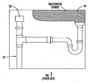
- FIG. 1 shows a typical application of an air admittance valve.
- Air admittance valves are normally closed, but open during a negative pressure condition, such as when wastewater is released. This allows air to enter the plumbing system and facilitate drainage. Once the flow of the wastewater ceases, the valve closes and remains closed until another negative pressure condition occurs. In such a manner, odors are prevented from escaping from the vent system.
- air admittance valves rely on gravity to close the valve once a negative pressure condition ceases.
- Such air admittance valves usually include sealing members that are constructed of multiple components.
- a rigid plate or frame structure is used to carry a thin flexible sealing member to and from closed and open positions.
- the thin flexible sealing member is bonded, stretched across, or otherwise fixed to the rigid frame structure.
- An example of such a design is described in U.S. Patent No. 4,535,807 .
- any detachment of the sealing member from the rigid frame structure is likely to result in inferior, and in some situations, failed performance of the air admittance valve.
- the ability of the sealing member to perform the sealing function is dictated by the accuracy of the dimensions of the frame structure. For instance, frame structures that have certain discontinuities, uneven surfaces, or other dimensional aberrations may not allow the sealing members to seal the valve in the closed position.
- the improved air admittance valve should be simpler and less expensive to manufacture, and should also provide enhanced performance with respect to the valve known from JP H11 325 289 , which provides a sealing member without a separate frame member.
- the present invention addresses the above needs and achieves other advantages by providing an air admittance valve configured when subjecte to a negative pressure condition to vent a pipe system to an ambient environment according to claim 1.
- the sealing member may further comprise a middle rib disposed between the inner and outer ribs.
- the lid may further comprise a top portion, and a side portion extending approximately perpendicularly from an outer perimeter of the top portion of the lid, the top and side portions of the lid each defining inner and outer surfaces such that the inner surfaces of the lid define a second chamber.
- the main body may further comprise an approximately cylindrically-shaped main body wall defining an inner surface and an outer surface, the main body further defining an internal communication element that extends inwardly from the inner surface of the main body wall, and wherein the internal communication element comprises a plurality of openings allowing communication therethrough between the first chamber and the second chamber.
- the one or more guiding elements may comprise a plurality of guiding elements that extend from the inner surface of the top portion of the lid.
- the plurality of guiding elements may comprise a plurality of triangularly-shaped ribs extending substantially downward from the inner surface of the top portion of the lid, the plurality of ribs defining a plurality of guiding edges and wherein the ribs are disposed radially about an imaginary center point.
- the main body may further comprise an approximately cylindrically-shaped main body wall defining an inner surface and an outer surface, wherein one end of the main body wall defines the inner valve seat, and wherein the main body further defines an external communication element that extends outwardly and at an angle from the outer surface of the main body wall such that an end of the external communication element defines the outer valve seat, wherein a third chamber is defined between the outer surface of the main body wall and the external communication element, and wherein the external communication element comprises a plurality of openings allowing communication therethrough between the third chamber and the ambient environment.
- a plurality of support walls may be disposed within the third chamber.
- the one or more guiding elements may comprise a plurality of guiding elements that extend from the internal communication element of the main body.
- the plurality of guiding elements may comprise a plurality of triangularly-shaped ribs extending from the internal communication element of the main body, and wherein the ribs may be disposed radially about an imaginary center point.
- the air admittance valve comprises a main body made of a rigid material, a flexible ring-shaped sealing member, and a lid made of a rigid material.
- the main body has top and bottom portions and is configured to sealingly attach to the pipe system proximate the bottom portion and a main body chamber configured to
- the main body also comprises an approximately cylindrically-shaped main body wall defining an inner surface and an outer surface, wherein one end of the main body wall defines an inner valve seat, and wherein the main body further defines an internal communication element and an external communication element, the internal communication element extending inwardly from the inner surface of the main body wall and comprising a plurality of openings allowing communication therethrough between the main body chamber and a lid chamber, the external communication element extending outwardly and at an angle from the outer surface of the main body wall such that an end of the external communication element defines an outer valve seat.
- An external communication chamber is defined between the outer surface of the main body wall and the external communication element, and the external communication element comprises a plurality of openings allowing communication therethrough between the external communication chamber and the ambient environment.
- a vent opening is defined between the inner and outer valves seats that is configured to provide communication between the external communication chamber and the lid chamber.
- the flexible ring-shaped sealing element is configured to move between a closed position and an open position, and the sealing element defines an outer perimeter surface, an inner perimeter surface, and opposite top and bottom surfaces extending between the outer and inner perimeter surfaces.
- the lid is made of a rigid material and is configured to sealingly attach to the main body proximate the top portion of the main body, the lid comprising a top portion, and a side portion extending approximately perpendicularly from an outer perimeter of the top portion, the top and side portions each defining inner and outer surfaces such that the inner surfaces define the lid chamber.
- the lid further comprises a plurality of triangularly-shaped ribs extending downward from the inner surface of the top portion of the lid and disposed radially about an imaginary center point such that the plurality of ribs define a plurality of guiding edges configured to guide the sealing element via the inner perimeter surface of the sealing element to and from the closed position, in which the bottom surface of the sealing element rests against the inner and outer valve seats of the main body thus blocking communication through the vent opening, and the open position, in which the sealing element rises off of the inner and outer valve seats such that the main body chamber communicates with the ambient environment through the vent opening, the lid chamber, and the external communication chamber.
- FIG.1 shows a common application of an air admittance valve in accordance with the prior art.
- an air admittance valve 20 communicates with a plumbing system 22 to vent the plumbing system upon the discharge of wastewater, such as from a wastewater source 24.
- wastewater such as from a wastewater source 24.
- the air admittance valve 20 opens upon discharge of the wastewater, it is normally closed to prevent the escape of gases from the plumbing system.
- many prior art air admittance valves include a rigid plate or frame structure that is used to carry a thin flexible sealing member to and from closed and open positions.
- these multipart constructions are not only difficult and expensive to manufacture, but sometimes result in poor performance due to inconsistencies in the frame structures.
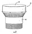
- FIG. 2 shows a perspective view of an assembled air admittance valve 50 in accordance with an exemplary embodiment of the present invention
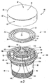
- FIG. 3 shows an exploded perspective view of the air admittance valve 50 in accordance with an exemplary embodiment of the present invention.
- the air admittance valve 50 according to various embodiments of the present invention includes a lid 60, a flexible sealing element 70 (not visible in FIG. 2 ) , and a main body 80. Referring to FIG.
- the lid 60 is made of a rigid thermoplastic material, such as, for example, polyvinyl chloride (PVC) or acrylonitrile butadiene styrene (ABS), and comprises a top portion 62 having an outer perimeter 63, and a side portion 64 that extends approximately perpendicularly from the outer perimeter 63 of the top portion 62.
- the top portion 62 includes an outer surface 65 and an inner surface 66 (inner surface 66 is visible in FIG. 4 ).
- the side portion 64 includes an outer surface 67 and an inner surface 68 (inner surface 68 is visible in FIG. 4 ).
- the lid may be constructed of any rigid material.
- a lid chamber 69 is defined by the inner surfaces 66, 68 of the lid 60 (lid chamber 69 is visible in FIG. 4 ).
- the lid 60 has a substantially circular top profile, which is designed to sealingly attach to the main body 80.
- the lid 60 and/or the main body 80 may have various other configurations and are not limited to the shapes and configurations shown in the figures.
- the lid 60 is constructed of a rigid material, and is attached to the main body 80 through the use of a sonic weld. In other embodiments however, the lid 60 may be secured to the main body 80 in any other manner designed to sealingly attach the lid 60 to the main body 80, including, but not limited to, other mechanical and/or chemical attachment methods.
- the sealing element 70 of the depicted embodiment is a ring-shaped seal constructed of a flexible material.
- the sealing element 70 could have a variety of shapes, including, for example, oblog, hourglass, and elliptical shapes.
- sealing element 70 comprises an outer perimeter surface 72, an inner perimeter surface 74, a top surface 76, and a bottom surface 78.
- the top and bottom surfaces 76, 78 are configured opposite of each other and extend between the outer perimeter surface 72 and the inner perimeter surface 74.
- the bottom surface 78 of the sealing member 70 defines a substantially planar surface in order to provide a seal for the air admittance valve 50.
- the top surface 76 of the sealing element 70 includes an outer rib 75, a middle rib 77, and an inner rib 79, wherein the ribs 75, 77, and 79 are substantially concentric about the center of the sealing element 70.
- the inner and outer ribs 75, 79 provide support for the sealing element in an area proximate the valve seats.
- the sealing member 70 is a unitary element constructed of a silicone material, however in other embodiments, various other configurations and materials are possible.
- the main body 80 of the air admittance valve 50 includes a top portion 82 and a bottom portion 84.
- the bottom portion 84 has a substantially cylindrical shape and includes a threaded section 86 proximate a distal end of the bottom portion 84.
- the threaded section 86 of the bottom portion 84 is defined in an outer surface of the bottom portion 84 so that the air admittance valve 50 may be affixed to an internally threaded end of an existing pipe system.
- the threaded section 86 could be defined by an inner surface of the bottom portion 84, or, in still other embodiments, other methods of attaching the air admittance valve 50 to the pipe system are possible.
- the cylindrical shape of the bottom portion 84 allows the depicted embodiment to interface with existing pipe systems, which often comprise substantially cylindrical pipes.
- the main body 80 of the air admittance valve 50 comprises an approximately cylindrically shaped main body wall 88 (seen more clearly in FIGS. 5 and 6 ) that defines an inner surface 90 and an outer surface 92.
- a main body chamber 93 (seen more clearly in FIGS. 5 and 6 ) is defined by the inner surface of the main body wall 88.
- the main body chamber 93 is configured to communicate with the attached pipe system.
- the main body 80 of the air admittance valve 50 is made of a rigid thermoplastic material, such as, for example, polyvinyl chloride (PVC) or acrylonitrile butadiene styrene (ABS). It should be noted that other embodiments, the main body 80 may be made of any rigid material. In some embodiments, such as the depicted embodiment, the material of the main body 80 may be chosen to complement the material of the lid 60. However, in other embodiments, the lid 50 and the main body 80 may be constructed of dissimilar materials.
- PVC polyvinyl chloride
- ABS acrylonitrile butadiene styrene
- the top end of the main body wall 88 defines a substantially circular surface having a rounded edge, thus defining an inner valve seat 95 of the air admittance valve 50.
- the main body wall 88 has a generally cylindrical shape, it necks inward between the bottom portion 84 and the top portion 82. In other embodiments, however, the main body wall 88 may have other configurations.
- the inner valve seat 95 of the depicted embodiment has a rounded profile, in other embodiments it could have various profiles configured to provide a seal with the sealing element 70.
- the top portion 82 of the air admittance valve 50 includes an external communication element 96 and an internal communication element 98.
- the external communication element 96 extends outwardly and upwardly at an angle from the outer surface 92 of the main body wall 88, and defines an external communication chamber 97 between the outer surface 92 and the external communication element 96.
- the end portion 99 of the external communication element 96 also defines an outer peripheral edge 101 upon which the lid 60 is attached.
- An end portion 99 of the external communication element 96 defines a substantially circular ring having a rounded edge, which defines an outer valve seat 100.
- the inner and outer valves seats 95, 100 are defined by the main body 80.
- the inner and outer valve seats may be defined by various other components, and in some embodiments the inner valve seat may be defined by one component and the outer valve seat may be defined by another component.
- the inner valve seat may be defined by the main body and the outer valve seat may be defined by the lid.
- the outer valve seat 100 of the depicted embodiment has a rounded profile, in other embodiments it could have various profiles configured to provide a seal with the sealing element 70. Additionally, in still other embodiments, the inner valve seat 95 and the outer valve seat 100 could have different profiles.
- the inner and outer valve seats 95, 100 are substantially concentric about the center of the main body wall 88, substantially co-planer with each other, and there is a vent opening 102 located between the valve seats 95,100.
- the vent opening 102 between the inner and outer valve seats 95, 100 is configured to allow venting through the vent opening 102, i.e., air can flow between the lid chamber 69 and the external communication chamber 97 via the vent opening 102.
- the external communication chamber 97 also includes a plurality of support elements 103 that extend between the outer surface 92 of the main body wall 88 and the external communication element 96.
- the plurality of support elements 103 are configured to prevent the sealing element 70 from becoming lodged in the external communication chamber 97, thus the plurality of support elements 103 are configured to provide support for the sealing element 70 should the sealing element tend to be drawn into the external communication chamber 97 through the vent opening 102 between the valve seats 95, 100. It should be noted that the plurality of support elements 103 are configured so as not to interfere with the ability of the valve 50 to allow communication of air through the vent opening 102 between the inner and outer valve seats 95, 100. Thus, in the depicted embodiment, a plurality of open areas 107 are defined between the plurality of support elements 103.
- the external communication element 96 is comprised of a plurality of projections 104 that extend between the outer surface 92 of the main body wall 88 and the end portion 99. As shown in the figure, the plurality of projections 104 define a plurality of openings 109 therebetween, such that the external communication element 96 allows communication of air between the ambient environment and the external communication chamber 97 through the openings 109. As will be described in more detail below, when the air admittance valve 50 is in an open position, air enters the air admittance valve 50 through the external communication element 96. As a result, the plurality of projections 104 act to protect the inside of the valve 50 from any debris or other materials that may tend to be carried by the air flow.
- an external communication element 96 may have other configurations, including smaller openings, larger openings, or combinations thereof.
- the external communication element 96 may have various other configurations, and in some embodiments, there need not be an external communication element 96.
- the main body 80 also defines an internal communication element 98 that extends inwardly and upwardly from the inner surface 90 of the main body wall 88 proximate the top end 94.
- the internal communication element 98 includes a mesh surface 110 ( FIG. 3 ) that extends to a top surface 112.
- the mesh surface 110 defines a plurality of openings 114, such that the internal communication element 98 allows communication of air through the openings 114.
- the mesh surface 110 acts to protect the inside of the valve 50 from any debris or other materials that may tend to be carried by the air flow, which may include various debris from the pipe system. It should be noted, however, in other embodiments of the present invention, other configurations of the internal communication element 98 are possible.
- any openings of the internal communication element 98 may have other configurations, including smaller openings, larger openings, or combinations thereof.
- the internal communication element 98 may have a various other configurations, and in some embodiments, there need not be an internal communication element.
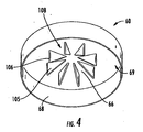
- FIG. 4 shows the underside of the lid 60.
- one or more guiding elements may extend from the lid 60.
- a plurality of guiding elements 105 extend from the inner surface 66 of the top portion 62 of the lid 60 into the lid chamber 69.
- a single guiding element may extend from the lid 60, such as, for example, a cylindrical element.
- the plurality of guiding elements 105 define a plurality of guiding surfaces 106 that extend downward from the inner surface 66 of the top portion 62.
- the plurality of guiding surfaces 106 are configured to guide the sealing member 70 by the inner perimeter surface 74 of the sealing member 70 to guide it as it moves between a closed position ( FIG . 5 ) and an open position ( FIG. 6 ).
- the plurality of guiding elements 105 comprises a plurality of substantially triangularly-shaped ribs that are radially disposed about an imaginary center point of the lid 60, and which define a plurality of open areas 108 therebetween such that air may be communicated within the lid chamber 69.
- the shape of the guiding elements 105 is configured to complement the shape of the internal communication element 98, however, in other embodiments the plurality of guiding elements 105 may have any configuration that provides a plurality of guiding surfaces 106 for guiding the sealing member 70 by the inner perimeter surface 74 of the sealing member 70 and that allow the lid 60 to be sealingly attached to the main body 80.
- one or more guiding elements may be part of the main body 80 and may extend up from the main body 80, rather than down from the lid 60.
- An example of an embodiment showing a plurality of guiding elements 105 extending from the main body 80 is depicted in FIG. 7 .
- one or more guiding elements 105 may be part of the lid 60 and one or more guiding elements 105 may be part of the main body 80.
- An example of such an embodiment is depicted in FIG. 8 .
- the plurality of guiding elements 105 includes a plurality of guiding surfaces 106 configured to guide the sealing element 70 by the inner perimeter surface 74 of the sealing element 70.
- FIG. 5 shows a cross-section view of the air admittance valve 50 in the closed position.
- the sealing element 70 rests via force of gravity on the inner and outer valve seats 95, 100 of the main body 80, thus covering the vent opening 102 between the inner and outer valve seats 95, 100.
- the sealing member 70 blocks communication through the vent opening 102 between the inner and outer valves seats 95,100.
- air communication between the pipe system and the ambient environment is blocked.
- the inner and outer ribs 75, 79 of the sealing element 70 may be configured to approximately line up with the inner and outer valve seats 95, 100 of the main body 80 so as to provide support via increased thickness in these areas, thus providing reinforcing support for the sealing element 70 in the areas of contact with the valve seats 95,100.
- the sealing member 70 is subjected to air pressure differentials that may tend to press the sealing member 70 downward into the external communication chamber 97.
- the middle rib 77 of the sealing element 70 is configured to be placed in an area between the inner and outer valve seats 95,100 and proximate the plurality of support elements 103 located in the external communication chamber 97 so as to provide support for the sealing member 70 should the sealing member 70 be pressed downward.
- the plurality of support elements 103 of the depicted embodiment tend to keep the sealing element 70 from becoming trapped in the external communication chamber, and the middle rib 75 provides reinforcing support for the sealing element 70 in an area of contact with the support elements 103.
- the plurality of support elements 103 do not extend up to the inner and outer valve seats 95, 100 so as not to interfere with the sealing of the valve seats 95,100.
- other support element designs are possible, and in still other embodiments there need not be any support elements in the external communication chamber 97.
- FIG. 6 shows a cross section view of the air admittance valve 50 in the open position.
- the open position is created by a negative pressure condition, which may be initiated when wastewater in the pipe system is released (such as, for example, by flushing a toilet or by draining a wastewater tub).
- the negative pressure condition causes the sealing element 70 to rise off of the inner and outer valve seats 95, 100, thus opening communication of air through the vent opening 102 between the inner and outer valve seats 95, 100.
- the sealing element 70 is guided into the lid chamber 69 via its inner perimeter surface 74 by the plurality of guiding surfaces 106 defined by the plurality of guiding elements 105.
- the sealing element 70 drops down from the lid chamber 69, again guided via its inner perimeter surface 74 by the plurality of guiding surfaces 106 defined by the plurality of guiding elements 105 and onto the inner and outer valve seats 95, 100, thus sealing the vent opening 102 between the valve seats 95, 100, and, closing the valve 50.
- the present invention improves on the prior art by providing an air admittance valve 50 having a sealing element 70 that is guided to and from open and closed positions via an inner perimeter surface 74 of the sealing element 70, and thus without the need for a separate guiding frame structure attached to the sealing member 70.
- the present invention provides a simpler air admittance valve design and that provides enhanced performance that is less expensive to manufacture.
Landscapes
- Engineering & Computer Science (AREA)
- General Engineering & Computer Science (AREA)
- Structural Engineering (AREA)
- Environmental & Geological Engineering (AREA)
- Health & Medical Sciences (AREA)
- Life Sciences & Earth Sciences (AREA)
- Hydrology & Water Resources (AREA)
- Public Health (AREA)
- Water Supply & Treatment (AREA)
- Mechanical Engineering (AREA)
- Self-Closing Valves And Venting Or Aerating Valves (AREA)
- Sink And Installation For Waste Water (AREA)
Claims (9)
- Soupape d'admission d'air (20, 50) configurée pour éventer un système de tuyauteries (22) vers l'environnement ambiant lorsqu'elle est soumise à une condition de pression négative, ladite soupape d'admission comprenant:- un corps principal (80) ayant des parties supérieure (62) et inférieure (84) et configuré pour s'attacher de manière étanche au système de tuyauteries proche de la partie inférieure (84), le corps principal (80) définissant également une première chambre (93) configurée pour communiquer avec le système de tuyauteries;- des sièges de soupape intérieur (95) et extérieur (100) qui définissent au moins une ouverture d'évent (102) située entre les sièges de soupape intérieur et extérieur (95, 100) et configurée pour communiquer avec l'environnement ambiant;- un élément d'étanchéité flexible (70) configuré pour se déplacer entre une position fermée et une position ouverte, l'élément d'étanchéité (70) définissant une surface périmétrique extérieure (72), une surface périmétrique intérieure (74) et des surfaces supérieure (76) et inférieure (78) opposées s'étendant entre les surfaces périmétriques extérieure et intérieure;- un couvercle (60) configuré pour s'attacher de manière étanche au corps principal (80), le couvercle (60) comprenant en outre un ou plusieurs éléments de guidage (105) qui définissent une ou plusieurs surfaces de guidage (106) configurées pour engager la surface périmétrique intérieure (74) de l'élément d'étanchéité (70) de façon à guider l'élément d'étanchéité vers et de la position fermée, dans laquelle la surface inférieure (78) de l'élément d'étanchéité repose sur les sièges de soupape intérieur (95) et extérieur (100), bloquant ainsi la communication à travers l'ouverture d'évent (102), et la position ouverte, dans laquelle l'élément d'étanchéité (70) soulève les sièges de soupape intérieur et extérieur (95, 100), de telle façon que la première chambre (93) communique avec l'environnement ambiant à travers l'ouverture d'évent (102), et- un élément de rigidification pour l'élément d'étanchéité (70),caractérisé en ce que
la surface supérieure (76) de l'élément d'étanchéité (70) inclut une nervure de support intérieure (79) et une nervure de support extérieure (75) comme éléments de rigidification de l'élément d'étanchéité (70), lesdites nervures intérieure et extérieure (75, 79) formant avec l'élément d'étanchéité (70) un élément unitaire dépourvu d'une structure à cadre rigide; et dans laquelle les nervures de support intérieure et extérieure sont configurées pour fournir un support pour l'élément d'étanchéité (70) proche des sièges de soupape intérieur et extérieur (95, 100), respectivement. - Soupape d'admission d'air suivant la revendication 1, caractérisée en ce que l'élément d'étanchéité (70) comprend en outre une nervure de médiane (77) disposée entre les nervures de support intérieure (79) et extérieure (75).
- Soupape d'admission d'air suivant la revendication 1, dans laquelle le couvercle (60) est attaché de manière étanche près d'une partie supérieure (62) du corps principal (80).
- Soupape d'admission d'air suivant la revendication 1, dans laquelle le couvercle (60) comprend une partie supérieure (62) et une partie latérale (64) approximativement perpendiculaires à la partie supérieure (62) et s'étendant depuis un périmètre extérieur (63) de la partie supérieure (62) du couvercle (60), les parties supérieure et latérale du couvercle définissant chacune des surfaces intérieure (66) et extérieure (65) telles que les surfaces intérieures du couvercle définissent une deuxième chambre (69).
- Soupape d'admission d'air suivant la revendication 1, dans laquelle le corps principal (80) comprend une paroi de corps principal de forme approximativement cylindrique (88) définissant une surface intérieure (90) et une surface extérieure (92), le corps principal définissant en outre un élément de communication interne (98) qui s'étend vers l'intérieur depuis la surface intérieure (90) de la paroi du corps principal (88), et dans laquelle l'élément de communication interne (98) comprend une pluralité d'ouvertures (114) permettant à travers elles la communication entre la première chambre (93) et la deuxième chambre (69).
- Soupape d'admission d'air suivant la revendication 1, dans laquelle le corps principal (80) comprend une paroi de corps principal de forme approximativement cylindrique (88) définissant une surface intérieure et une surface extérieure (90, 92), dans laquelle une extrémité de la paroi de corps principal (88) définit le siège de soupape intérieur (95), et dans laquelle le corps principal définit en outre un élément de communication externe (96) qui s'étend vers l'extérieur et selon un angle depuis la surface extérieure (92) de la paroi de corps principal, de telle façon qu'une extrémité de l'élément de communication externe (96) définit le siège de soupape extérieur (100), dans laquelle une troisième chambre (97) est définie entre la surface extérieure (92) de la paroi de corps principal (88) et l'élément de communication externe (96), et dans laquelle l'élément de communication externe (96) comprend une pluralité d'ouvertures (109) permettant à travers elles la communication entre la troisième chambre (97) et l'environnement ambiant.
- Soupape d'admission d'air suivant la revendication 1, dans laquelle les un ou plusieurs éléments de guidage (105) sont une pluralité d'éléments de guidage qui s'étendent depuis la surface intérieure (66) de la partie supérieure (62) du couvercle (60).
- Soupape d'admission d'air suivant la revendication 7, dans laquelle la pluralité d'éléments de guidage (105) comprend une pluralité de nervures de forme triangulaire (105) s'étendant essentiellement vers le bas depuis la surface intérieure (66) de la partie supérieure (62) du couvercle (60), la pluralité de nervures définissant une pluralité de bords de guidage (106) et dans laquelle les nervures sont disposées radialement autour d'un point central imaginaire.
- Soupape d'admission d'air suivant la revendication 6, dans laquelle une pluralité de parois de support (103) sont disposées à l'intérieur de la troisième chambre (97).
Applications Claiming Priority (2)
| Application Number | Priority Date | Filing Date | Title |
|---|---|---|---|
| US12/188,680 US8136548B2 (en) | 2008-08-08 | 2008-08-08 | Air admittance valve |
| PCT/IB2009/006453 WO2010015915A1 (fr) | 2008-08-08 | 2009-08-05 | Soupape d'admission d'air |
Publications (2)
| Publication Number | Publication Date |
|---|---|
| EP2318599A1 EP2318599A1 (fr) | 2011-05-11 |
| EP2318599B1 true EP2318599B1 (fr) | 2016-04-20 |
Family
ID=41395107
Family Applications (1)
| Application Number | Title | Priority Date | Filing Date |
|---|---|---|---|
| EP09786103.3A Active EP2318599B1 (fr) | 2008-08-08 | 2009-08-05 | Soupape d'admission d'air |
Country Status (15)
| Country | Link |
|---|---|
| US (1) | US8136548B2 (fr) |
| EP (1) | EP2318599B1 (fr) |
| JP (1) | JP2011530681A (fr) |
| KR (1) | KR101135852B1 (fr) |
| AU (1) | AU2009278898B2 (fr) |
| CA (1) | CA2674985C (fr) |
| DK (1) | DK2318599T3 (fr) |
| ES (1) | ES2572202T3 (fr) |
| HU (1) | HUE029648T2 (fr) |
| MX (1) | MX2009008372A (fr) |
| NZ (1) | NZ590928A (fr) |
| PL (1) | PL2318599T3 (fr) |
| PT (1) | PT2318599T (fr) |
| TW (1) | TWI402445B (fr) |
| WO (1) | WO2010015915A1 (fr) |
Cited By (1)
| Publication number | Priority date | Publication date | Assignee | Title |
|---|---|---|---|---|
| CN108930813A (zh) * | 2017-05-22 | 2018-12-04 | 三花亚威科电器设备(芜湖)有限公司 | 一种流量控制装置 |
Families Citing this family (21)
| Publication number | Priority date | Publication date | Assignee | Title |
|---|---|---|---|---|
| DE202011001194U1 (de) * | 2011-01-03 | 2011-05-05 | Wilhelm Schauerte Gmbh & Co. Kg | Be-/Entlüftungsautomat mit Elastomer-Membran 2 |
| KR101070808B1 (ko) * | 2011-04-26 | 2011-10-07 | 주식회사 에브윈 | 오배수 통기밴트 |
| US10663192B2 (en) | 2013-01-04 | 2020-05-26 | Fleming Vaughn Carroll | Vertical vent stack cap |
| US9416986B2 (en) | 2013-06-24 | 2016-08-16 | The Rectorseal Corporation | Valve for roof vent |
| KR101472968B1 (ko) * | 2013-09-04 | 2014-12-16 | 주식회사 에브윈 | 오배수 배관용 에어벤트 |
| BR112016013024B1 (pt) * | 2013-12-09 | 2023-04-18 | Raval A.C.S. Ltd | Dispositivo de drenagem, sistema de vapor de combustível, e, tanque de combustível |
| WO2015109306A1 (fr) * | 2014-01-20 | 2015-07-23 | Dayco Ip Holdings, Llc | Clapet anti-retour à élément d'étanchéité amélioré |
| US9683355B2 (en) | 2014-04-28 | 2017-06-20 | Ips Corporation | Air admittance valve |
| DE102014006647A1 (de) * | 2014-05-07 | 2015-11-12 | Dürr Systems GmbH | Reinigungsgerät für einen Zerstäuber und zugehöriges Betriebsverfahren |
| WO2016112063A1 (fr) | 2015-01-09 | 2016-07-14 | Dayco Ip Holdings, Llc | Dispositif d'évacuation de ventilation de carter moteur |
| KR200478332Y1 (ko) * | 2015-02-25 | 2015-09-18 | 주식회사 에스엠지 | 양흡입 에어 벤트 밸브 |
| DE102015004532B3 (de) * | 2015-04-02 | 2016-09-29 | Capricorn S. A. | Belüftungsventil für ein Kanalisationsrohr |
| WO2016168261A1 (fr) | 2015-04-13 | 2016-10-20 | Dayco Ip Holdings, Llc | Dispositifs de production de vide par effet venturi |
| CN107850092B (zh) | 2015-07-17 | 2020-11-06 | 戴科知识产权控股有限责任公司 | 在推进区段中具有多个子通道和推进出口的用于使用文丘里效应来产生真空的装置 |
| US10190455B2 (en) | 2015-10-28 | 2019-01-29 | Dayco Ip Holdings, Llc | Venturi devices resistant to ice formation for producing vacuum from crankcase gases |
| GB201600622D0 (en) * | 2016-01-13 | 2016-02-24 | Floplast Ltd | Valve |
| CA3032684A1 (fr) * | 2016-08-12 | 2018-02-15 | Oatey Co. | Soupape d'admission d'air |
| CN110135084B (zh) * | 2019-05-20 | 2023-01-13 | 河北工程大学 | 一种复杂不确定性条件下的农机半轴可靠性分析方法 |
| KR102319339B1 (ko) * | 2021-01-25 | 2021-10-29 | 주식회사 에스엠지 | 통기 벤트 |
| KR102356646B1 (ko) * | 2021-06-15 | 2022-02-08 | 주식회사 투엔티원 | 건축물의 오배수관용 통기밸브 |
| KR20230001982U (ko) | 2022-04-08 | 2023-10-17 | (주)투엔티원 | 건축물의 오배수관용 와류형 통기밸브 |
Citations (1)
| Publication number | Priority date | Publication date | Assignee | Title |
|---|---|---|---|---|
| JPH11325289A (ja) * | 1998-05-18 | 1999-11-26 | Kobayashi Seisakusho:Kk | 排水管内の圧力調節弁 |
Family Cites Families (42)
| Publication number | Priority date | Publication date | Assignee | Title |
|---|---|---|---|---|
| US35535A (en) | 1862-06-10 | Improvement in lam p-chi mneys | ||
| US35532A (en) * | 1862-06-10 | Improvement in feet-warming apparatus | ||
| US1739430A (en) * | 1928-01-05 | 1929-12-10 | Walter O Webster | Relief valve |
| US2520771A (en) * | 1949-01-22 | 1950-08-29 | Smith Corp A O | Diaphragm valve |
| US2704996A (en) * | 1952-07-17 | 1955-03-29 | Hannifin Corp | Fluid operated cylinder with adjustable cushion |
| US2928413A (en) * | 1954-10-20 | 1960-03-15 | Black Sivalls & Bryson Inc | Relief valve |
| US3073339A (en) * | 1959-05-01 | 1963-01-15 | Kelsey Hayes Co | Check valves |
| AT238870B (de) * | 1962-10-24 | 1965-03-10 | Hoerbiger Ventilwerke Ag | Ringventil |
| SE377146B (fr) * | 1973-10-15 | 1975-06-23 | Ba Installationsutveckling Ab | |
| SE433863B (sv) * | 1977-08-31 | 1984-06-18 | Sture Ericson | Automatisk ventilanordning for anslutning till ett sanitert avloppsror |
| SE417345B (sv) * | 1978-09-12 | 1981-03-09 | Bengt Arne Persson | Luftningsventil |
| NL8200799A (nl) * | 1982-02-26 | 1983-09-16 | Dipat Nv | Beluchtingsinrichting. |
| US4493339A (en) * | 1982-05-05 | 1985-01-15 | Porter Instrument Company, Inc. | Air valve for a breathing system |
| EP0100657B1 (fr) * | 1982-07-29 | 1986-10-15 | Kentsub Limited | Soupape d'admission d'air |
| BE895071A (fr) * | 1982-11-19 | 1983-03-16 | Ericson Sture | Dispositif de valve a air automatique pour canalisations |
| GB8703132D0 (en) * | 1987-02-11 | 1987-03-18 | Earl R F | Air admittance valve |
| US4991623A (en) * | 1989-01-26 | 1991-02-12 | Ericson Kurt Sture Birger | Automatic air valves for ducts |
| US4974632A (en) * | 1989-01-26 | 1990-12-04 | Ericson Kurt Sture Birger | Automatic air valves for ducts |
| GB8913009D0 (en) * | 1989-06-06 | 1989-07-26 | Frawley Patrick D | One way air admittance valve |
| GB8916772D0 (en) | 1989-07-21 | 1989-09-06 | Polypipe Plc | A valve |
| US5419366A (en) * | 1992-07-28 | 1995-05-30 | Johnston; Ian F. | Valve |
| US5273068A (en) * | 1993-04-20 | 1993-12-28 | Duren Gary S | Air admittance valve for resisting high internal pressure |
| US5441679A (en) * | 1993-06-03 | 1995-08-15 | Studor, Inc. | Method of assembling a value head |
| SE503815C2 (sv) * | 1995-06-22 | 1996-09-09 | Durgo Ab | Luftningsventil |
| US5706854A (en) * | 1996-08-21 | 1998-01-13 | Haynes; George William | Venturi vent valve |
| US5971014A (en) * | 1996-09-04 | 1999-10-26 | Duren; Gary S. | Vacuum breaker valve vent fitting clean-out device |
| US5913330A (en) * | 1996-12-19 | 1999-06-22 | Enardo Manufacturing Company | Pressure/vacuum relief valve assembly |
| SE506788C2 (sv) * | 1997-03-07 | 1998-02-09 | Durgo Ab | Luftningsventil |
| EP1026329A1 (fr) * | 1999-02-03 | 2000-08-09 | Kurt Sture Birger Ericson | Soupape d'admission d'air pour système de canalisation d'eaux usées sanitaires |
| US6308731B1 (en) * | 1999-06-25 | 2001-10-30 | Itz Corporation | Vent valve |
| JP4364391B2 (ja) * | 2000-03-21 | 2009-11-18 | 株式会社キッツ | 排水用通気装置 |
| US6234198B1 (en) * | 2000-04-27 | 2001-05-22 | Daniel Chalich | Air vent valve |
| US6415816B1 (en) * | 2000-08-31 | 2002-07-09 | Cherne Industries Incorporated | Air admittance valve assembly |
| FR2816025B1 (fr) | 2000-10-30 | 2002-12-13 | Claude Jean Marie Frangin | Clapet d'entree d'air |
| US6557825B2 (en) * | 2001-03-30 | 2003-05-06 | Cherne Industries Incorporated | Air admittance valve connector assembly |
| PL62447Y1 (pl) | 2003-02-17 | 2006-07-31 | Michalina Kaczmarczyk | Napowietrzacz kanalizacyjny PL PL |
| US7422030B2 (en) | 2004-07-15 | 2008-09-09 | Cherne Industries Incorporated | Air admittance valve assembly |
| US7445022B2 (en) * | 2005-01-18 | 2008-11-04 | Ayrlett Air Valve Company, Llc | Air admittance vent diaphragm assembly |
| US20060237678A1 (en) * | 2005-04-25 | 2006-10-26 | Lackey Derek J | Metallic Air Admittance Valve |
| JP4063851B2 (ja) | 2006-04-13 | 2008-03-19 | 前澤化成工業株式会社 | 吸気弁 |
| US7270146B1 (en) * | 2006-12-15 | 2007-09-18 | Wilhelmina E. E. Johnston | Air vent valve |
| CA2678710C (fr) | 2007-02-21 | 2015-12-01 | Orc Technology Pty Ltd | Dispositif d'evacuation du trop-plein d'egout |
-
2008
- 2008-08-08 US US12/188,680 patent/US8136548B2/en active Active
-
2009
- 2009-08-04 TW TW98126253A patent/TWI402445B/zh active
- 2009-08-05 PT PT97861033T patent/PT2318599T/pt unknown
- 2009-08-05 NZ NZ59092809A patent/NZ590928A/xx unknown
- 2009-08-05 ES ES09786103T patent/ES2572202T3/es active Active
- 2009-08-05 EP EP09786103.3A patent/EP2318599B1/fr active Active
- 2009-08-05 HU HUE09786103A patent/HUE029648T2/en unknown
- 2009-08-05 AU AU2009278898A patent/AU2009278898B2/en active Active
- 2009-08-05 WO PCT/IB2009/006453 patent/WO2010015915A1/fr active Application Filing
- 2009-08-05 KR KR1020117005510A patent/KR101135852B1/ko active IP Right Grant
- 2009-08-05 MX MX2009008372A patent/MX2009008372A/es active IP Right Grant
- 2009-08-05 PL PL09786103.3T patent/PL2318599T3/pl unknown
- 2009-08-05 JP JP2011521652A patent/JP2011530681A/ja active Pending
- 2009-08-05 DK DK09786103.3T patent/DK2318599T3/en active
- 2009-08-07 CA CA 2674985 patent/CA2674985C/fr active Active
Patent Citations (1)
| Publication number | Priority date | Publication date | Assignee | Title |
|---|---|---|---|---|
| JPH11325289A (ja) * | 1998-05-18 | 1999-11-26 | Kobayashi Seisakusho:Kk | 排水管内の圧力調節弁 |
Cited By (2)
| Publication number | Priority date | Publication date | Assignee | Title |
|---|---|---|---|---|
| CN108930813A (zh) * | 2017-05-22 | 2018-12-04 | 三花亚威科电器设备(芜湖)有限公司 | 一种流量控制装置 |
| CN108930813B (zh) * | 2017-05-22 | 2020-02-18 | 三花亚威科电器设备(芜湖)有限公司 | 一种流量控制装置 |
Also Published As
| Publication number | Publication date |
|---|---|
| HUE029648T2 (en) | 2017-03-28 |
| CA2674985A1 (fr) | 2010-02-08 |
| PL2318599T3 (pl) | 2016-10-31 |
| ES2572202T3 (es) | 2016-05-30 |
| US20100032028A1 (en) | 2010-02-11 |
| DK2318599T3 (en) | 2016-06-27 |
| US8136548B2 (en) | 2012-03-20 |
| KR101135852B1 (ko) | 2012-04-16 |
| WO2010015915A1 (fr) | 2010-02-11 |
| NZ590928A (en) | 2012-10-26 |
| MX2009008372A (es) | 2010-03-22 |
| TW201028575A (en) | 2010-08-01 |
| AU2009278898A1 (en) | 2010-02-11 |
| PT2318599T (pt) | 2016-07-15 |
| CA2674985C (fr) | 2014-02-11 |
| AU2009278898B2 (en) | 2015-08-20 |
| TWI402445B (zh) | 2013-07-21 |
| JP2011530681A (ja) | 2011-12-22 |
| EP2318599A1 (fr) | 2011-05-11 |
| KR20110067092A (ko) | 2011-06-21 |
Similar Documents
| Publication | Publication Date | Title |
|---|---|---|
| EP2318599B1 (fr) | Soupape d'admission d'air | |
| CA2532944C (fr) | Diaphragme de prise d'air | |
| CA2420307C (fr) | Ensemble clapet d'admission d'air | |
| AU2018203313B2 (en) | Air admittance valve | |
| US20060011239A1 (en) | Air admittance valve assembly | |
| US5937889A (en) | Inlet air filter for vacuum breaker valves | |
| US20070083989A1 (en) | Anti-flushing diaphragm | |
| EP2241686B1 (fr) | Soupape d'admission d'air haute capacité pour systèmes de canalisations d'eaux usées sanitaires | |
| JP2008256114A (ja) | 通気弁 | |
| JP4304369B2 (ja) | 通気機能付き床排水トラップ | |
| JP4184416B2 (ja) | 排水用通気装置 | |
| CN111295487B (zh) | 带有通风口的虹吸管 | |
| NZ739145B2 (en) | Air admittance valve |
Legal Events
| Date | Code | Title | Description |
|---|---|---|---|
| PUAI | Public reference made under article 153(3) epc to a published international application that has entered the european phase |
Free format text: ORIGINAL CODE: 0009012 |
|
| 17P | Request for examination filed |
Effective date: 20110304 |
|
| AK | Designated contracting states |
Kind code of ref document: A1 Designated state(s): AT BE BG CH CY CZ DE DK EE ES FI FR GB GR HR HU IE IS IT LI LT LU LV MC MK MT NL NO PL PT RO SE SI SK SM TR |
|
| AX | Request for extension of the european patent |
Extension state: AL BA RS |
|
| DAX | Request for extension of the european patent (deleted) | ||
| 17Q | First examination report despatched |
Effective date: 20140204 |
|
| TPAC | Observations filed by third parties |
Free format text: ORIGINAL CODE: EPIDOSNTIPA |
|
| GRAP | Despatch of communication of intention to grant a patent |
Free format text: ORIGINAL CODE: EPIDOSNIGR1 |
|
| INTG | Intention to grant announced |
Effective date: 20151201 |
|
| GRAS | Grant fee paid |
Free format text: ORIGINAL CODE: EPIDOSNIGR3 |
|
| GRAA | (expected) grant |
Free format text: ORIGINAL CODE: 0009210 |
|
| AK | Designated contracting states |
Kind code of ref document: B1 Designated state(s): AT BE BG CH CY CZ DE DK EE ES FI FR GB GR HR HU IE IS IT LI LT LU LV MC MK MT NL NO PL PT RO SE SI SK SM TR |
|
| REG | Reference to a national code |
Ref country code: GB Ref legal event code: FG4D |
|
| REG | Reference to a national code |
Ref country code: CH Ref legal event code: EP |
|
| REG | Reference to a national code |
Ref country code: AT Ref legal event code: REF Ref document number: 792616 Country of ref document: AT Kind code of ref document: T Effective date: 20160515 |
|
| REG | Reference to a national code |
Ref country code: IE Ref legal event code: FG4D |
|
| REG | Reference to a national code |
Ref country code: ES Ref legal event code: FG2A Ref document number: 2572202 Country of ref document: ES Kind code of ref document: T3 Effective date: 20160530 |
|
| REG | Reference to a national code |
Ref country code: DE Ref legal event code: R096 Ref document number: 602009038023 Country of ref document: DE |
|
| REG | Reference to a national code |
Ref country code: DK Ref legal event code: T3 Effective date: 20160623 |
|
| REG | Reference to a national code |
Ref country code: SE Ref legal event code: TRGR |
|
| REG | Reference to a national code |
Ref country code: CH Ref legal event code: NV Representative=s name: FREI PATENTANWALTSBUERO AG, CH |
|
| REG | Reference to a national code |
Ref country code: NL Ref legal event code: FP |
|
| REG | Reference to a national code |
Ref country code: RO Ref legal event code: EPE |
|
| REG | Reference to a national code |
Ref country code: PT Ref legal event code: SC4A Ref document number: 2318599 Country of ref document: PT Date of ref document: 20160715 Kind code of ref document: T Free format text: AVAILABILITY OF NATIONAL TRANSLATION Effective date: 20160630 |
|
| REG | Reference to a national code |
Ref country code: NO Ref legal event code: T2 Effective date: 20160420 |
|
| REG | Reference to a national code |
Ref country code: FR Ref legal event code: PLFP Year of fee payment: 8 |
|
| REG | Reference to a national code |
Ref country code: CH Ref legal event code: PCOW Free format text: NEW ADDRESS: 38, BOULEVARD NAPOLEON 1ER, 2210 LUXEMBOURG (LU) |
|
| RAP2 | Party data changed (patent owner data changed or rights of a patent transferred) |
Owner name: STUDOR S.A. |
|
| REG | Reference to a national code |
Ref country code: AT Ref legal event code: MK05 Ref document number: 792616 Country of ref document: AT Kind code of ref document: T Effective date: 20160420 Ref country code: EE Ref legal event code: FG4A Ref document number: E012222 Country of ref document: EE Effective date: 20160715 |
|
| PG25 | Lapsed in a contracting state [announced via postgrant information from national office to epo] |
Ref country code: AT Free format text: LAPSE BECAUSE OF FAILURE TO SUBMIT A TRANSLATION OF THE DESCRIPTION OR TO PAY THE FEE WITHIN THE PRESCRIBED TIME-LIMIT Effective date: 20160420 Ref country code: HR Free format text: LAPSE BECAUSE OF FAILURE TO SUBMIT A TRANSLATION OF THE DESCRIPTION OR TO PAY THE FEE WITHIN THE PRESCRIBED TIME-LIMIT Effective date: 20160420 |
|
| REG | Reference to a national code |
Ref country code: DE Ref legal event code: R097 Ref document number: 602009038023 Country of ref document: DE |
|
| REG | Reference to a national code |
Ref country code: SK Ref legal event code: T3 Ref document number: E 22462 Country of ref document: SK Ref country code: GR Ref legal event code: EP Ref document number: 20160401684 Country of ref document: GR Effective date: 20161020 |
|
| PLBE | No opposition filed within time limit |
Free format text: ORIGINAL CODE: 0009261 |
|
| STAA | Information on the status of an ep patent application or granted ep patent |
Free format text: STATUS: NO OPPOSITION FILED WITHIN TIME LIMIT |
|
| PG25 | Lapsed in a contracting state [announced via postgrant information from national office to epo] |
Ref country code: SM Free format text: LAPSE BECAUSE OF FAILURE TO SUBMIT A TRANSLATION OF THE DESCRIPTION OR TO PAY THE FEE WITHIN THE PRESCRIBED TIME-LIMIT Effective date: 20160420 |
|
| REG | Reference to a national code |
Ref country code: HU Ref legal event code: AG4A Ref document number: E029648 Country of ref document: HU |
|
| 26N | No opposition filed |
Effective date: 20170123 |
|
| PG25 | Lapsed in a contracting state [announced via postgrant information from national office to epo] |
Ref country code: MC Free format text: LAPSE BECAUSE OF FAILURE TO SUBMIT A TRANSLATION OF THE DESCRIPTION OR TO PAY THE FEE WITHIN THE PRESCRIBED TIME-LIMIT Effective date: 20160420 |
|
| PG25 | Lapsed in a contracting state [announced via postgrant information from national office to epo] |
Ref country code: SI Free format text: LAPSE BECAUSE OF FAILURE TO SUBMIT A TRANSLATION OF THE DESCRIPTION OR TO PAY THE FEE WITHIN THE PRESCRIBED TIME-LIMIT Effective date: 20160420 |
|
| REG | Reference to a national code |
Ref country code: FR Ref legal event code: PLFP Year of fee payment: 9 |
|
| PG25 | Lapsed in a contracting state [announced via postgrant information from national office to epo] |
Ref country code: CY Free format text: LAPSE BECAUSE OF FAILURE TO SUBMIT A TRANSLATION OF THE DESCRIPTION OR TO PAY THE FEE WITHIN THE PRESCRIBED TIME-LIMIT Effective date: 20160420 Ref country code: LV Free format text: LAPSE BECAUSE OF NON-PAYMENT OF DUE FEES Effective date: 20170805 |
|
| PG25 | Lapsed in a contracting state [announced via postgrant information from national office to epo] |
Ref country code: MK Free format text: LAPSE BECAUSE OF FAILURE TO SUBMIT A TRANSLATION OF THE DESCRIPTION OR TO PAY THE FEE WITHIN THE PRESCRIBED TIME-LIMIT Effective date: 20160420 Ref country code: MT Free format text: LAPSE BECAUSE OF NON-PAYMENT OF DUE FEES Effective date: 20160831 |
|
| REG | Reference to a national code |
Ref country code: FR Ref legal event code: PLFP Year of fee payment: 10 |
|
| REG | Reference to a national code |
Ref country code: CH Ref legal event code: PCAR Free format text: NEW ADDRESS: POSTFACH, 8032 ZUERICH (CH) |
|
| REG | Reference to a national code |
Ref country code: DE Ref legal event code: R082 Ref document number: 602009038023 Country of ref document: DE Representative=s name: SONNENBERG HARRISON PARTNERSCHAFT MBB PATENT- , DE Ref country code: DE Ref legal event code: R082 Ref document number: 602009038023 Country of ref document: DE Representative=s name: SONNENBERG HARRISON PARTNERSCHAFT MBB, DE Ref country code: DE Ref legal event code: R082 Ref document number: 602009038023 Country of ref document: DE Representative=s name: 24IP LAW GROUP SONNENBERG FORTMANN, DE |
|
| REG | Reference to a national code |
Ref country code: CH Ref legal event code: NV Representative=s name: 24IP LAW GROUP SONNENBERG FORTMANN, CH |
|
| REG | Reference to a national code |
Ref country code: DE Ref legal event code: R082 Ref document number: 602009038023 Country of ref document: DE Representative=s name: SONNENBERG HARRISON PARTNERSCHAFT MBB, DE Ref country code: DE Ref legal event code: R082 Ref document number: 602009038023 Country of ref document: DE Representative=s name: 24IP LAW GROUP SONNENBERG FORTMANN, DE Ref country code: DE Ref legal event code: R081 Ref document number: 602009038023 Country of ref document: DE Owner name: AKATHERM B.V., NL Free format text: FORMER OWNER: STUDOR S.A., LUXEMBURG/LUXEMBOURG, LU |
|
| REG | Reference to a national code |
Ref country code: NL Ref legal event code: PD Owner name: AKATHERM B.V.; NL Free format text: DETAILS ASSIGNMENT: CHANGE OF OWNER(S), ASSIGNMENT; FORMER OWNER NAME: STUDOR S.A. Effective date: 20191025 |
|
| REG | Reference to a national code |
Ref country code: CH Ref legal event code: PUE Owner name: AKATHERM B.V., NL Free format text: FORMER OWNER: STUDOR S.A., LU |
|
| REG | Reference to a national code |
Ref country code: ES Ref legal event code: PC2A Owner name: AKATHERM B.V. Effective date: 20191028 |
|
| REG | Reference to a national code |
Ref country code: EE Ref legal event code: GB1A Ref document number: E012222 Country of ref document: EE |
|
| REG | Reference to a national code |
Ref country code: NO Ref legal event code: CREP Representative=s name: BRYN AARFLOT AS, STORTINGSGATA 8, 0161 OSLO, NORGE Ref country code: NO Ref legal event code: CHAD Owner name: AKATHERM B.V., NL |
|
| REG | Reference to a national code |
Ref country code: LU Ref legal event code: PD Owner name: AKATHERM B.V.; NL Free format text: FORMER OWNER: STUDOR S.A. Effective date: 20191028 |
|
| REG | Reference to a national code |
Ref country code: GB Ref legal event code: 732E Free format text: REGISTERED BETWEEN 20191128 AND 20191204 |
|
| REG | Reference to a national code |
Ref country code: HU Ref legal event code: GB9C Owner name: AKATHERM B.V., NL Free format text: FORMER OWNER(S): STUDOR S.A., LU Ref country code: HU Ref legal event code: FH1C Free format text: FORMER REPRESENTATIVE(S): DANUBIA SZABADALMI ES JOGI IRODA KFT., HU Representative=s name: SBGK SZABADALMI UEGYVIVOEI IRODA, HU |
|
| REG | Reference to a national code |
Ref country code: SK Ref legal event code: PC4A Ref document number: E 22462 Country of ref document: SK Owner name: AKATHERM B.V., NK PANNINGEN, NL Free format text: FORMER OWNER: STUDOR S.A., 2210 LUXEMBOURG, LU Effective date: 20191203 |
|
| REG | Reference to a national code |
Ref country code: BE Ref legal event code: PD Owner name: AKATHERM B.V.; NL Free format text: DETAILS ASSIGNMENT: CHANGE OF OWNER(S), CESSION; FORMER OWNER NAME: STUDOR S.A. Effective date: 20191112 |
|
| PGFP | Annual fee paid to national office [announced via postgrant information from national office to epo] |
Ref country code: DK Payment date: 20200824 Year of fee payment: 12 Ref country code: IS Payment date: 20200817 Year of fee payment: 12 Ref country code: CZ Payment date: 20200730 Year of fee payment: 12 Ref country code: LU Payment date: 20200820 Year of fee payment: 12 Ref country code: FI Payment date: 20200819 Year of fee payment: 12 Ref country code: NO Payment date: 20200821 Year of fee payment: 12 Ref country code: RO Payment date: 20200727 Year of fee payment: 12 Ref country code: LT Payment date: 20200724 Year of fee payment: 12 Ref country code: EE Payment date: 20200818 Year of fee payment: 12 Ref country code: TR Payment date: 20200728 Year of fee payment: 12 Ref country code: SK Payment date: 20200727 Year of fee payment: 12 |
|
| PGFP | Annual fee paid to national office [announced via postgrant information from national office to epo] |
Ref country code: LV Payment date: 20200819 Year of fee payment: 12 Ref country code: HU Payment date: 20200822 Year of fee payment: 12 Ref country code: SE Payment date: 20200825 Year of fee payment: 12 Ref country code: BG Payment date: 20200831 Year of fee payment: 12 |
|
| REG | Reference to a national code |
Ref country code: DE Ref legal event code: R082 Ref document number: 602009038023 Country of ref document: DE Representative=s name: SONNENBERG HARRISON PARTNERSCHAFT MBB PATENT- , DE Ref country code: DE Ref legal event code: R082 Ref document number: 602009038023 Country of ref document: DE Representative=s name: SONNENBERG HARRISON PARTNERSCHAFT MBB, DE |
|
| PGFP | Annual fee paid to national office [announced via postgrant information from national office to epo] |
Ref country code: PT Payment date: 20210728 Year of fee payment: 13 |
|
| REG | Reference to a national code |
Ref country code: LT Ref legal event code: MM4D Effective date: 20210805 |
|
| REG | Reference to a national code |
Ref country code: EE Ref legal event code: MM4A Ref document number: E012222 Country of ref document: EE Effective date: 20210831 |
|
| REG | Reference to a national code |
Ref country code: DK Ref legal event code: EBP Effective date: 20210831 |
|
| REG | Reference to a national code |
Ref country code: FI Ref legal event code: MAE |
|
| REG | Reference to a national code |
Ref country code: NO Ref legal event code: MMEP |
|
| REG | Reference to a national code |
Ref country code: SE Ref legal event code: EUG |
|
| REG | Reference to a national code |
Ref country code: SK Ref legal event code: MM4A Ref document number: E 22462 Country of ref document: SK Effective date: 20210805 |
|
| PG25 | Lapsed in a contracting state [announced via postgrant information from national office to epo] |
Ref country code: LT Free format text: LAPSE BECAUSE OF NON-PAYMENT OF DUE FEES Effective date: 20210805 Ref country code: HU Free format text: LAPSE BECAUSE OF NON-PAYMENT OF DUE FEES Effective date: 20210806 Ref country code: FI Free format text: LAPSE BECAUSE OF NON-PAYMENT OF DUE FEES Effective date: 20210805 Ref country code: BG Free format text: LAPSE BECAUSE OF NON-PAYMENT OF DUE FEES Effective date: 20220228 |
|
| PG25 | Lapsed in a contracting state [announced via postgrant information from national office to epo] |
Ref country code: SE Free format text: LAPSE BECAUSE OF NON-PAYMENT OF DUE FEES Effective date: 20210806 Ref country code: RO Free format text: LAPSE BECAUSE OF NON-PAYMENT OF DUE FEES Effective date: 20210805 Ref country code: NO Free format text: LAPSE BECAUSE OF NON-PAYMENT OF DUE FEES Effective date: 20210831 Ref country code: LV Free format text: LAPSE BECAUSE OF NON-PAYMENT OF DUE FEES Effective date: 20210805 Ref country code: LU Free format text: LAPSE BECAUSE OF NON-PAYMENT OF DUE FEES Effective date: 20210805 Ref country code: EE Free format text: LAPSE BECAUSE OF NON-PAYMENT OF DUE FEES Effective date: 20210831 Ref country code: CZ Free format text: LAPSE BECAUSE OF NON-PAYMENT OF DUE FEES Effective date: 20210805 |
|
| PG25 | Lapsed in a contracting state [announced via postgrant information from national office to epo] |
Ref country code: SK Free format text: LAPSE BECAUSE OF NON-PAYMENT OF DUE FEES Effective date: 20210805 Ref country code: DK Free format text: LAPSE BECAUSE OF NON-PAYMENT OF DUE FEES Effective date: 20210831 |
|
| PG25 | Lapsed in a contracting state [announced via postgrant information from national office to epo] |
Ref country code: PT Free format text: LAPSE BECAUSE OF NON-PAYMENT OF DUE FEES Effective date: 20230206 |
|
| P01 | Opt-out of the competence of the unified patent court (upc) registered |
Effective date: 20230524 |
|
| PGFP | Annual fee paid to national office [announced via postgrant information from national office to epo] |
Ref country code: NL Payment date: 20230823 Year of fee payment: 15 |
|
| PGFP | Annual fee paid to national office [announced via postgrant information from national office to epo] |
Ref country code: IT Payment date: 20230831 Year of fee payment: 15 Ref country code: IE Payment date: 20230821 Year of fee payment: 15 Ref country code: GB Payment date: 20230824 Year of fee payment: 15 Ref country code: ES Payment date: 20230918 Year of fee payment: 15 Ref country code: CH Payment date: 20230902 Year of fee payment: 15 |
|
| PGFP | Annual fee paid to national office [announced via postgrant information from national office to epo] |
Ref country code: PL Payment date: 20230726 Year of fee payment: 15 Ref country code: GR Payment date: 20230818 Year of fee payment: 15 Ref country code: FR Payment date: 20230811 Year of fee payment: 15 Ref country code: DE Payment date: 20230822 Year of fee payment: 15 Ref country code: BE Payment date: 20230822 Year of fee payment: 15 |