EP2316351B1 - Medizinisches Instrument zum Setzen von Gewebeklammern - Google Patents
Medizinisches Instrument zum Setzen von Gewebeklammern Download PDFInfo
- Publication number
- EP2316351B1 EP2316351B1 EP10188207.4A EP10188207A EP2316351B1 EP 2316351 B1 EP2316351 B1 EP 2316351B1 EP 10188207 A EP10188207 A EP 10188207A EP 2316351 B1 EP2316351 B1 EP 2316351B1
- Authority
- EP
- European Patent Office
- Prior art keywords
- clip
- cap
- tubular shaft
- proctological
- distal end
- Prior art date
- Legal status (The legal status is an assumption and is not a legal conclusion. Google has not performed a legal analysis and makes no representation as to the accuracy of the status listed.)
- Active
Links
- 238000005452 bending Methods 0.000 claims 2
- 210000000056 organ Anatomy 0.000 description 14
- 239000004744 fabric Substances 0.000 description 8
- 230000015572 biosynthetic process Effects 0.000 description 5
- 238000005755 formation reaction Methods 0.000 description 5
- 238000010276 construction Methods 0.000 description 4
- 230000001960 triggered effect Effects 0.000 description 3
- 208000004680 Rectal Fistula Diseases 0.000 description 2
- 206010002156 anal fistula Diseases 0.000 description 2
- 238000006073 displacement reaction Methods 0.000 description 2
- 239000000463 material Substances 0.000 description 2
- 230000007246 mechanism Effects 0.000 description 2
- 238000000034 method Methods 0.000 description 2
- 238000007493 shaping process Methods 0.000 description 2
- 210000005070 sphincter Anatomy 0.000 description 2
- 241000251730 Chondrichthyes Species 0.000 description 1
- 244000261422 Lysimachia clethroides Species 0.000 description 1
- 235000008331 Pinus X rigitaeda Nutrition 0.000 description 1
- 235000011613 Pinus brutia Nutrition 0.000 description 1
- 241000018646 Pinus brutia Species 0.000 description 1
- 208000027418 Wounds and injury Diseases 0.000 description 1
- 210000001072 colon Anatomy 0.000 description 1
- 230000000112 colonic effect Effects 0.000 description 1
- 230000001419 dependent effect Effects 0.000 description 1
- 238000005553 drilling Methods 0.000 description 1
- 230000005489 elastic deformation Effects 0.000 description 1
- 238000011010 flushing procedure Methods 0.000 description 1
- 238000002513 implantation Methods 0.000 description 1
- 238000003780 insertion Methods 0.000 description 1
- 230000037431 insertion Effects 0.000 description 1
- 238000004519 manufacturing process Methods 0.000 description 1
- 239000007769 metal material Substances 0.000 description 1
- 230000000149 penetrating effect Effects 0.000 description 1
- 229920001296 polysiloxane Polymers 0.000 description 1
- 230000008569 process Effects 0.000 description 1
- 230000007480 spreading Effects 0.000 description 1
- 229910001220 stainless steel Inorganic materials 0.000 description 1
- 239000010935 stainless steel Substances 0.000 description 1
- 230000003068 static effect Effects 0.000 description 1
- 208000037816 tissue injury Diseases 0.000 description 1
- 230000007704 transition Effects 0.000 description 1
Images


Classifications
-
- A—HUMAN NECESSITIES
- A61—MEDICAL OR VETERINARY SCIENCE; HYGIENE
- A61B—DIAGNOSIS; SURGERY; IDENTIFICATION
- A61B17/00—Surgical instruments, devices or methods
- A61B17/10—Surgical instruments, devices or methods for applying or removing wound clamps, e.g. containing only one clamp or staple; Wound clamp magazines
-
- A—HUMAN NECESSITIES
- A61—MEDICAL OR VETERINARY SCIENCE; HYGIENE
- A61B—DIAGNOSIS; SURGERY; IDENTIFICATION
- A61B1/00—Instruments for performing medical examinations of the interior of cavities or tubes of the body by visual or photographical inspection, e.g. endoscopes; Illuminating arrangements therefor
- A61B1/00064—Constructional details of the endoscope body
- A61B1/00071—Insertion part of the endoscope body
- A61B1/0008—Insertion part of the endoscope body characterised by distal tip features
- A61B1/00087—Tools
-
- A—HUMAN NECESSITIES
- A61—MEDICAL OR VETERINARY SCIENCE; HYGIENE
- A61B—DIAGNOSIS; SURGERY; IDENTIFICATION
- A61B17/00—Surgical instruments, devices or methods
- A61B17/08—Wound clamps or clips, i.e. not or only partly penetrating the tissue ; Devices for bringing together the edges of a wound
- A61B17/083—Clips, e.g. resilient
-
- A—HUMAN NECESSITIES
- A61—MEDICAL OR VETERINARY SCIENCE; HYGIENE
- A61B—DIAGNOSIS; SURGERY; IDENTIFICATION
- A61B1/00—Instruments for performing medical examinations of the interior of cavities or tubes of the body by visual or photographical inspection, e.g. endoscopes; Illuminating arrangements therefor
- A61B1/31—Instruments for performing medical examinations of the interior of cavities or tubes of the body by visual or photographical inspection, e.g. endoscopes; Illuminating arrangements therefor for the rectum, e.g. proctoscopes, sigmoidoscopes, colonoscopes
-
- A—HUMAN NECESSITIES
- A61—MEDICAL OR VETERINARY SCIENCE; HYGIENE
- A61B—DIAGNOSIS; SURGERY; IDENTIFICATION
- A61B17/00—Surgical instruments, devices or methods
- A61B17/12—Surgical instruments, devices or methods for ligaturing or otherwise compressing tubular parts of the body, e.g. blood vessels or umbilical cord
- A61B17/122—Clamps or clips, e.g. for the umbilical cord
- A61B17/1227—Spring clips
-
- A—HUMAN NECESSITIES
- A61—MEDICAL OR VETERINARY SCIENCE; HYGIENE
- A61B—DIAGNOSIS; SURGERY; IDENTIFICATION
- A61B17/00—Surgical instruments, devices or methods
- A61B17/00234—Surgical instruments, devices or methods for minimally invasive surgery
- A61B2017/00292—Surgical instruments, devices or methods for minimally invasive surgery mounted on or guided by flexible, e.g. catheter-like, means
- A61B2017/00296—Surgical instruments, devices or methods for minimally invasive surgery mounted on or guided by flexible, e.g. catheter-like, means mounted on an endoscope
-
- A—HUMAN NECESSITIES
- A61—MEDICAL OR VETERINARY SCIENCE; HYGIENE
- A61B—DIAGNOSIS; SURGERY; IDENTIFICATION
- A61B17/00—Surgical instruments, devices or methods
- A61B17/00234—Surgical instruments, devices or methods for minimally invasive surgery
- A61B2017/00292—Surgical instruments, devices or methods for minimally invasive surgery mounted on or guided by flexible, e.g. catheter-like, means
- A61B2017/003—Steerable
- A61B2017/00318—Steering mechanisms
- A61B2017/00331—Steering mechanisms with preformed bends
-
- A—HUMAN NECESSITIES
- A61—MEDICAL OR VETERINARY SCIENCE; HYGIENE
- A61B—DIAGNOSIS; SURGERY; IDENTIFICATION
- A61B17/00—Surgical instruments, devices or methods
- A61B17/28—Surgical forceps
- A61B17/29—Forceps for use in minimally invasive surgery
- A61B2017/2901—Details of shaft
- A61B2017/2904—Details of shaft curved, but rigid
-
- A—HUMAN NECESSITIES
- A61—MEDICAL OR VETERINARY SCIENCE; HYGIENE
- A61B—DIAGNOSIS; SURGERY; IDENTIFICATION
- A61B17/00—Surgical instruments, devices or methods
- A61B17/32—Surgical cutting instruments
- A61B2017/32006—Surgical cutting instruments with a cutting strip, band or chain, e.g. like a chainsaw
Definitions
- the present invention relates to a medical, preferably proctological instrument for setting tissue clips according to the preamble of patent claim 1.
- Such a device uses a shaft-like tissue clip delivery means for closing a tissue injury such as an anal fistula and the like diseased tissue changes.
- tissue clip of this type is well known in terms of its basic construction. For a better understanding, this clip will be described below with reference to the Fig. 1 described in more detail.
- such a clip 100 consists of a mouth-like clamping device with two toothed pines 110, 120, which can be opened and closed via two lateral hinges 130 or via flexible formations.
- the hinges 130 and the flexible formations are preferably formed from elastic bands which, when the jaws 110, 120 are opened, store a spring energy which, when the jaws 110, 120, i. when the hinges 130 or the flexible formations are triggered, the jaws 110, 120 snap in with a predetermined clamping force.
- each clip 100 is integrally stamped or laser cut from a spring plate by a ring from the spring plate with partially different
- Ring width is worked out.
- Two diametrically opposite ring sections with large ring width form the two jaws 110, 120, whereas the two intermediate ring sections with a narrow ring width, the hinges 130 and the flexible (elastic) formations result.
- the jaws 110, 120 are formed by arching the ring sections with large ring width over the flat side arcuate, whereas the two ring sections with narrow ring width about its longitudinal axis by about 180 ° twisted (twisted) are formed to form the hinges.
- This special shape of the lasered spring plate creates the shape of a kind of shark mouth with two mutually moving tooth rows, which are formed by lasers of the ring sections with a large ring width.
- endoscopic implantation of a medical device as a whole constitutes the most compatible method for the patient.
- the medical device must be fixed to the inside of a hollow organ.
- a number (at least one) of the tissue clips, clips or anchors described above are introduced into the hollow organ by means of an endoscope or a similar shaft-like delivery means and placed at predetermined locations on the inner side of the organ.
- the respective clip or anchor is brought to the organ tissue and triggered the biasing spring for snapping the clip or clamping the anchor. This then holds or pinches a tissue fold between its jaws or its hooks or needles with a predetermined clamping or spreading force, with the teeth, hooks, needles or prongs of each jaw drilling into the tissue and preferably penetrating it.
- endoscope or shaft-like feeding means is usually equipped with an endoscope head or endoscope cap, which in addition to the generally required for an endoscope functions such as lighting, optics and optionally rinsing device additionally has a holding and removing device for the tissue clip. It should be noted that in this entire application under an endoscope and a simple insertion without their own lighting and optics and flushing function can be understood.
- the holding and removal device consists essentially of an expansion sleeve and a manually or remotely operable slide, which is movable in Endoskoplnaturescardi.
- the expansion sleeve is designed such that the already opened Gewebeclip can be placed on the sleeve, such that a slipping back of the clip during its introduction into the hollow organ can be prevented.
- the slider is positioned axially behind the clip and serves as an axial stop for the clip.
- the slider is moved axially forward and thereby strips the clip over the expansion sleeve.
- the clip is triggered, ie the above based on the Fig. 1 described biasing mechanism within the clip is released during stripping of the expansion sleeve and the two jaws of the tissue clip snap under pinching the intervening tissue to.
- the exact setting of the tissue clip with the known device is very difficult, especially in the vicinity of the sphincter.
- the object of the present invention is therefore to provide a medical, preferably proctological instrument for setting tissue clips by means of which a tissue clip or a tissue clamp in the vicinity of the sphincter in the inner organ wall (colonic wall) can be easily and reliably obtained. can be set
- the proctological instrument has an instrument handle on which a rigid tube shaft is mounted at its proximal end, at the distal end of a cap is fixed or formed, on which a fabric clip is preferably placed resiliently by means of a trigger or puller of the cap is removable.
- a rigid tube shaft is mounted at its proximal end, at the distal end of a cap is fixed or formed, on which a fabric clip is preferably placed resiliently by means of a trigger or puller of the cap is removable.
- Either the cap itself or the Tube shaft is bent in its distal end portion in an area immediately in front of the cap at a predetermined fixed angle (> 0 °), so that the cap-defined removal direction for the clip is aligned at the angle to the tubular shaft axis. In this way, the cap can be better attached to the surface of the organ wall and thus the clip can be positioned more accurately.
- the trigger or puller is formed with a pull or pressure element which extends along the tubular shaft in at least one outer tube fixed to the tubular functional channel and is coupled to an actuating lever on the instrument handle.
- the tension or pressure element is connected at its distal end with a stripping ring, which sits longitudinally displaceable on the cap and by means of which the clip is removable. As a result, tilting of the clip during the removal process can be avoided.
- tubular shaft in its distal end region directly in front of the cap in S-shape, wherein the withdrawal direction of the cap extends at the fixed angle to the imaginary straight central axis of the tubular shaft.
- the S-shape returns the cap parallel to the imaginary central axis (i.e., it protrudes less laterally) and thus can be better inserted into the hollow organ.
- the medical (proctological) instrument consists of a preferably rigid or rigid tubular shaft 6 (for example made of a stainless steel), at the proximal end of an actuating handle 40 and at the distal end of a shaft head 1 with a triggering or removal device for a tissue clip mounted thereon 4 is mounted.
- a preferably rigid or rigid tubular shaft 6 for example made of a stainless steel
- the handle 40 preferably made of a Kunststoffgußteil, has a mounting portion 40 a, in which the tubular shaft 6 is inserted, pressed, clamped or cast and a holding portion 40 b, which extends at an angle to the tubular shaft 6. Furthermore, an actuating lever 41 is provided, which is guided either along the tubular shaft 6 slidably on this or hinged to the holding portion 40 b of the handle 40.
- the slidably guided operating lever 41 is direct and the hinged operating lever 41 is coupled via a gear train or the likeoperationsübertragungs- or deflection mechanism (not shown) with a tensile and / or pressure element 11, the present along the tubular shaft 6 is mounted in a fixed to the tubular shaft 6 guide 42, for example in the form of a Bowden cable.
- the tension and / or pressure element 11 is in turn coupled to a Gewebeklipab scheme adopted, by means of a preferably on the shaft head 1 resiliently alsratier tissue clip 4 in the above with reference to the Fig. 1 described construction is mounted.
- the shaft head 1 from a kind of cap (made of a plastic material), which has a Aufsteckabêt 1 a (preferably a silicone sheath), which surrounds the distal end portion of the rigid tubular shaft 6 in the mounted state.
- a Aufsteckabêt 1 a preferably a silicone sheath
- the cap 1 is formed at the axial distance to Aufsteckabêt 1a shell side to or with an expansion sleeve (expansion sleeve portion) 3, which in the present embodiment with the Aufsteckabêt 1 a positively connected (verclipt). But it can also be integrally connected to the slip-on 1a or glued or welded to this.
- On the expansion sleeve 3 of the tissue clip 4 can be pushed, as above, based on Fig. 1 has been described in detail and thus also belongs to the subject invention.
- the expansion sleeve 3 projects axially beyond the distal end side of the tubular shaft 6 and thus forms a cup or cup-shaped sleeve section rounded radially outwards at its front edge.
- the Aufsteckabites 1 a is frictionally attached to the distal end of the tubular shaft 6. But it can also be glued, be pressed or potted with the tubular shaft 6.
- the expansion sleeve 3 has a front end groove 7 introduced in the axial direction from its distal end side into the shell-side cap or sleeve wall which preferably opens as a part-circle or crescent-shaped (circumferential) slot on the distal end side of the expansion sleeve 3 and whose groove bottom forms an abutment 8 at an axially rearward location, preferably approximately in an axially middle section of the expansion sleeve 3.
- the radius of the end groove 7 is chosen to be greater than the outer radius of the expansion sleeve 3, so that the sleeve wall in the formation of the end groove 7 receives two correspondingly spaced slots in the circumferential direction.
- FIG. 2a Another variant of providing a front groove according to the above definition is the additional arrangement of a preferably curved in the axial direction tab or tongue, as in particular in the Fig. 2a is shown, whose root is formed integrally with the cap and extending axially to form the groove at a radial distance from the cap skirt wall in the direction of the expansion sleeve.
- the jacket wall is not split (as described above), but it is an additional component in the form of the tab on the jacket wall of the cap out.
- This tab can be dimensioned so narrow that it remains straight in cross-section (without radius), ie it does not necessarily follow the cap circumference.
- plan shape of the tab can then be designed largely as desired, ie it can thicken and / or widen in the direction of tab root (transition region between the tab and cap), so as to obtain a greater rigidity.
- the tongue root itself can be dimensioned and designed according to static aspects to achieve the highest possible rigidity.
- the tab 9 extends according to the invention, the stop 8 performing groove bottom in the direction of the distal end face of the cap 1 and the expansion sleeve 3, wherein the rounded free leading edge relative to the distal front edge of the expansion axially slightly reset.
- the end groove 7 does not extend exactly parallel to the cap center axis but is inclined in the direction of the distal end side to the central axis, so that a plugged therein clip 4 can slide more easily forward.
- the groove 7 is not rectilinear but whose groove walls, at least the outer groove wall, are slightly curved in the axial direction, such that the groove 7, at least the tab 9 bulges radially outward in its axial center portion. In this way, the collapse behavior of a sliding fabric clip 4 with the construction according to the Fig. 1 already geometrically approved or facilitated in this state.
- this is provided with a radial outer through hole 10 through which a thread 11, cable or fabric is guided from the inside of the groove in the direction of the outside of the cap 1 and fixed therein.
- the thread 11, cable or fabric forms the aforementioned tension element.
- the one end of the thread is knotted to the tab outer side for this purpose, so that retraction of the thread 11 is prevented by the radial through hole 10.
- the cap 1 is at a position substantially radially opposite to the above-mentioned through-hole 10, i.
- the inner through hole 12 is located axially in front of the distal end side of the tubular shaft 6, so that the thread 11 coming from the inner through hole 12 in a on the shaft end side opening, extending on the outside of the tubular shaft 6 functional channel (guide) 42 is threadable, which forms the above-mentioned leadership of the tension element 11.
- the tubular shaft 6 is further bent or bent in the region of its distal end portion (ie in an area immediately in front of the cap 1), so that the discharge direction defined by the expansion sleeve 3 for the tissue clip 4 at a (fixed) angle (> 0 °) Pipe axis runs.
- tissue clip 4 For example according to the Fig. 1 To bring to its predetermined position, this must first on the expansion sleeve 3 of the butt plate. 1 be raised. For this purpose, lower and upper jaw of tissue clips 4 are opened by hand, so that the clip 4 can be attached to the rounded front edge of the expansion sleeve 3 and pushed over them. In this case, the trailing edge of the tissue clip 4 penetrates into the end groove 7 of the butt plate 1, thereby pulling the thread 11 out of the functional channel 42 on the instrument shaft 6.
- the sliding movement of the clip 4 comes with its coming into abutment on the groove bottom 8, wherein the clip 4 and the entrained thread 11 in Fig. 2 occupy the shown spatial position. That is, in this position, the clip 4 is fully wound on the cap 1 and can be placed over the tubular shaft 6 in a hollow organ. The thread 11 engages around the trailing edge of the clip 4 and thus receives a U-shape viewed in the thread longitudinal direction.
- the expansion sleeve 3 is pressed against the organ wall. If the clip 4 are now stripped, the thread 11, which is guided through the functional channel 42 to the proximal operating lever 41, pulled by longitudinal displacement of the actuating lever 41, wherein the end groove 7 in the radial direction traversing thread section shortened. Since the thread 11 is fixed in the outer through-hole 10, this exerts a force in the axial direction with a corresponding translation on the pulley principle on the clip 4, whereby the clip 4 is displaced in the direction of the distal end of the endoscope cap 1. Due to the outer rounding of the front Sp Schwarzhülsenkante and the soft, i.
- arched shaping of the end groove 7 facilitates slipping of the clip 4 over the front edge of the expansion sleeve 3 and further reduces the applied over the thread 11 maximum displacement force.
- Fig. 3 and 4 shows a further embodiment of the invention, wherein in the following only the different features to the above embodiment will be discussed.
- the puller of the second preferred embodiment of the invention consists of a stripping ring 50 which is pulled onto the expansion sleeve 3 and rests against an outer shaft shoulder 51 in the middle region of the butt plate 1.
- the Abziehring 50 but also create against the groove bottom of a Stirnnut according to the above embodiment axially.
- the thread passed through the above-described inner through hole is directly attached to the peeling ring 50 by having a through hole (in the longitudinal direction) inserted therein through which the thread is guided and fixed therein.
- an axial web 53 or an axial groove is formed on the outer circumference of the expansion sleeve 3, which engages in an axial inner groove of the stripping ring 50 or an axial inner web and forms an axial guide for the stripping ring 50.
- the peeling ring 50 is preferably adapted to the fabric clip in terms of its shape, so that it can be applied substantially accurately to the ring 50 and thus occupies a predetermined (rotational) position on the expansion sleeve 3.
- two threads can be provided in two functional channels 42.
- the fabric clip 4 is peeled off.
- the thread 11 has to be pulled along the tubular shaft 6, as a result of which the pull-off ring 50 moves forward in the direction of the distal end edge of the expansion sleeve 3.
- the clip 4 is moved forward until it jumps through the spring bias on the distal end edge of the expansion sleeve 3 and clamps the organ tissue between his jaws.
- the triggering or removal device for the tissue clip 4 has been actuated by a pulling movement of the thread 11. But it may also be the case that the actuation of the actuating lever 41 leads to a pressure movement of the pressure element, whereby the trigger or puller is not pulled forward but pushed.
- This alternative is especially in the Fig. 4 indicated.
- a wire or a flexible push rod 60 in each case two laterally mounted on the tubular shaft 6 guide channels 42 are respectively mounted, which are each connected at its distal end to the stripping ring 50. If the hinged or displaceably mounted actuating lever 41 is pivoted / displaced, this movement is transmitted from the preferably two push rods 60 to the stripping ring 50, thereby triggering the clip 4.
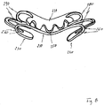
- FIG. 5 A third preferred embodiment of the invention is shown, which is based on the second embodiment. In the following, only the features different from those of the second embodiment will be described below.
- the rigid tubular shaft 6 is not simply bent at the distal end portion, but has in this area a gooseneck or S-shape, wherein the defined by the expansion sleeve 3 discharge direction at an angle (> 0 °) with respect to the straight tubular shaft portion in the central region and proximal portion of the tubular shaft 6 is aligned.
- the expansion sleeve 3 with respect to a (imaginary) center line of the tubular shaft 6 can be set back parallel thereto, so that an inserted into the colon of a patient instrument does not or only slightly widen the Organwandung.
- the holding portion 40b of the instrument handle 40 are folded with respect to the tubular shaft 6.
- the holding portion 40b is hinged on a hinge on the mounting portion 40a of the handle 40 and possibly locked there.
- folding over the handle 40b results in a screwdriver handle position, whereby the handling of the instrument is improved in the inserted position.
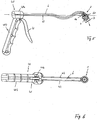
- a tissue clip is shown, which was developed especially for the proctological instrument according to the invention.
- This clip 200 also consists of a mouth-like clamping device, which has a toothed upper jaw 210 and a toothed lower jaw 220.
- the clip 200 according to the invention is punched or laser cut in one piece from a sheet or sheet metal material. It consists essentially of a closed ring with the two diametrically opposed upper and lower jaw sections 210, 220, which are each formed of a wide piece of leaf and two diametrically opposite, and each offset by 90 ° to the jaw sections arranged hinge portions 230, 240, which connect the jaw sections 210, 220 together.
- the jaw portions 210, 220 are formed at their respective longitudinal edges with teeth or teeth 250, which traverse the ring and interlock.
- the hinge portions 230, 240 are formed from a substantially narrower against the jaw portions 210, 220 strip-shaped leaf piece, which is bulged over the respective entire circle segment circumference substantially semicircular inward, that is towards the ring center. This results in the ring two diametrically opposite, semi-circular or partially circular Projections 260, 270, which form the hinges of the two jaw sections 210, 220.
- the ring is folded over or bent over its flat side in the region of the two hinge sections by approximately 180 °.
- the two hinge portions 230, 240 are bent perpendicular to the plane of the rings in their respective transitional areas 280, 290 to the upper and lower jaws so that the semicircular or semicircular bulge 260, 270 to the outside, i. Aligned away from the center of the ring.
- the jaw portions 210, 220 are also bent or curved over their entire circumference portion also perpendicular to the ring plane, but in the opposite direction to the Umbiegraum the hinge portions 230, 240 direction.
- tissue clip 200 may be used as an anchor for a medical instrument or the like.
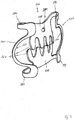
- Fig. 8 is an alternative embodiment of the tissue clip 200 according to the Fig. 7 shown, wherein follow only the geometric differences from the clip 200 according to the Fig. 7 should be described.
Landscapes
- Health & Medical Sciences (AREA)
- Life Sciences & Earth Sciences (AREA)
- Surgery (AREA)
- Molecular Biology (AREA)
- General Health & Medical Sciences (AREA)
- Biomedical Technology (AREA)
- Heart & Thoracic Surgery (AREA)
- Medical Informatics (AREA)
- Nuclear Medicine, Radiotherapy & Molecular Imaging (AREA)
- Animal Behavior & Ethology (AREA)
- Engineering & Computer Science (AREA)
- Public Health (AREA)
- Veterinary Medicine (AREA)
- Physics & Mathematics (AREA)
- Biophysics (AREA)
- Optics & Photonics (AREA)
- Pathology (AREA)
- Radiology & Medical Imaging (AREA)
- Surgical Instruments (AREA)
Description
- Die vorliegende Erfindung betrifft ein medizinisches, vorzugsweise proktologisches Instrument zum Setzen von Gewebeklammern gemäß dem Oberbegriff des Patentanspruchs 1.
- Eine derartige Vorrichtung verwendet ein schaftartiges Zuführmittel für einen Gewebeclip zum Verschließen einer Gewebeverletzung wie beispielsweise eine Analfistel und dergleichen krankhafte Gewebeveränderungen.
- Aus dem Stand der Technik beispielsweise gemäß der
US 6,849,078 B2 ist ein Gewebeclip dieser Gattung hinsichtlich seiner grundsätzlichen Konstruktion allgemein bekannt. Zum besseren Verständnis wird dieser Clip nachstehend unter Verweis auf dieFig. 1 näher beschrieben. - Demzufolge besteht ein solcher Clip 100 aus einer maulartigen Klemmeinrichtung mit zwei gezahnten Kiefern 110, 120, welche über zwei seitliche Scharniere 130 bzw. über flexible Ausformungen auf- und zugeklappt werden können. Die Scharniere 130 bzw. die flexiblen Ausformungen sind dabei vorzugsweise aus federelastischen Bändern ausgebildet, welche beim Aufklappen der Kiefer 110, 120 eine Federenergie speichern, die beim Freigeben der Kiefer 110, 120, d.h. bei einem Auslösen der Scharniere 130 bzw. der flexiblen Ausformungen zu einem Zuschnappen der Kiefer 110, 120 mit vorbestimmter Klemmkraft führt.
- Im Einzelnen ist jeder Clip 100 einstückig aus einem Federblech gestanzt oder gelasert, indem aus dem Federblech ein Ring mit partiell unterschiedlicher
- Ringbreite herausgearbeitet wird. Zwei diametrisch gegenüberliegende Ringabschnitte mit großer Ringbreite bilden die beiden Kiefer 110, 120, wohingegen die beiden dazwischen liegenden Ringabschnitte mit schmaler Ringbreite die Scharniere 130 bzw. die flexiblen (elastischen) Ausformungen ergeben. Die Kiefer 110, 120 sind dadurch ausgebildet, indem die Ringabschnitte mit großer Ringbreite über deren Flachseite bogenförmig gewölbt werden, wohingegen die beiden Ringabschnitte mit schmaler Ringbreite um ihre Längsachse um ca. 180° verdreht (tordiert) ausgebildet sind, um die Scharniere auszuformen. Durch diese besondere Formgebung des gelaserten Federblechs entsteht die Form einer Art Haifischmaul mit zwei aufeinander sich zu bewegenden Zahnreihen, welche durch Lasern der Ringabschnitte mit großer Ringbreite gebildet werden.
- Die Funktionsweise des vorstehend beschriebenen medizinischen Gewebeclip 100 lässt sich wie Folgt beschreiben:
- Im Allgemeinen stellt eine endoskopische Implantation einer medizinischen Vorrichtung insgesamt das für den Patienten verträglichste Verfahren dar. In diesem Fall muss die medizinische Vorrichtung von der Innenseite eines Hohlorgans an diesem fixiert werden. Zu diesem Zweck werden eine Anzahl (mindestens eine) der vorstehend beschriebenen Gewebeklammern, Clips oder Anker mittels eines Endoskops oder eines ähnlichen schaftartigen Zuführmittels in das Hohlorgan eingeführt und an vorbestimmten Stellen an der Organinnenseite platziert. Hiefür wird der jeweilige Clip oder Anker an das Organgewebe herangeführt und die Vorspannfeder für ein Zuschnappen des Clip oder Aufspannen des Ankers ausgelöst. Dieser hält oder klemmt daraufhin eine Gewebefalte zwischen seinen Kiefern oder seinen Haken oder Nadeln mit einer vorbestimmten Klemm- oder Spreizkraft ein, wobei sich die Zähne, Haken, Nadeln oder Zacken jedes Kiefers in das Gewebe bohren und dieses vorzugsweise durchdringen.
- Das in der
Fig. 1 nicht weiter dargestellte Endoskop oder schaftartige Zuführmittel ist in der Regel mit einem Endoskopkopf oder einer Endoskopkappe ausgerüstet, welche neben den für ein Endoskop generell erforderlichen Funktionen wie Beleuchtung, Optik und ggf. Spülvorrichtung zusätzlich eine Halte- und Abzieheinrichtung für den Gewebeclip aufweist. An dieser Stelle sei darauf hingewiesen, dass in dieser gesamten Anmeldung unter einem Endoskop auch eine einfache Einführhilfe ohne eigene Beleuchtung und Optik sowie Spülfunktion verstanden werden kann. - Die Halte- und Abzieheinrichtung besteht im Wesentlichen aus einer Spreizhülse sowie einem manuell oder ferngesteuert betätigbaren Schieber, der in Endoskoplängsrichtung bewegbar ist. Die Spreizhülse ist dabei derart ausgebildet, dass der bereits geöffnete Gewebeclip auf die Hülse aufgesetzt werden kann, derart, dass ein nach hinten Rutschen des Clip während dessen Einführung in das Hohlorgan verhinderbar ist. Zu diesem Zweck ist der Schieber axial hinter dem Clip positioniert und dient quasi als Axialanschlag für den Clip.
- Sobald der Clip an einer bestimmten Stelle platziert werden soll, wird der Schieber axial nach vorne bewegt und streift dabei den Clip über die Spreizhülse ab. Dabei wird der Clip ausgelöst, d.h. der vorstehend anhand der
Fig. 1 beschriebene Vorspannmechanismus innerhalb des Clip wird beim Abstreifen von der Spreizhülse freigegeben und die beiden Kiefer des Gewebeclip schnappen unter Einklemmen des dazwischen liegenden Gewebes zu. Es hat sich jedoch gezeigt, dass das genaue Setzen des Gewebeclip mit der bekannten Vorrichtung insbesondere im nahen Bereich des Schließmuskels sehr schwierig ist. - Angesichts dieses Stands der Technik besteht die Aufgabe der vorliegenden Erfindung daher darin, ein medizinisches, vorzugsweise proktologisches Instrument zum Setzen von Gewebeklammern zu schaffen, mittels dem auf einfache und sichere Weise ein Gewebeclip oder eine Gewebeklammer im Nahbereich des Schließmuskels in der inneren Organwand (Kolonwand) gesetzt werden kann
- Diese Aufgabe wird durch medizinisches, vorzugsweise proktologisches Instrument gelöst, welche die technischen Merkmale gemäß dem Patentanspruch 1 aufweist. Vorteilhafte Ausgestaltungen der Erfindung sind dabei Gegenstand der Unteransprüche.
- Erfindungsgemäß hat das proktologische Instrument einen Instrumentengriff, an welchem ein biegesteifer Rohrschaft an seinem proximalen Ende montiert ist, an dessen distalem Ende eine Kappe fixiert oder ausgebildet ist, auf die ein Gewebeclip vorzugsweise federelastisch aufgesetzt ist, der mittels einer Auslöse- oder Abziehvorrichtung von der Kappe abziehbar ist. Entweder die Kappe selbst oder der Rohrschaft ist in seinem distalen Endabschnitt in einem Bereich unmittelbar vor der Kappe in einem vorbestimmten fixen Winkel (> 0°) abgekröpft ist, sodass die von der Kappe definierte Abziehrichtung für den Clip in dem Winkel zur Rohrschaftsachse ausgerichtet ist. Auf diese Weise kann die Kappe besser an der Oberfläche der Organwand angesetzt und somit der Clip exakter positioniert werden.
- Vorzugsweise ist die Auslöse- oder Abziehvorrichtung mit einem Zug- oder Druckelement ausgebildet, das längs des Rohrschafts in zumindest einem am Rohrschaft fixierten äußeren Funktionskanal verläuft und mit einem Betätigungshebel am Instrumentengriff gekoppelt ist. In vorteilhafter Weise ist das Zug- oder Druckelement an seinem distalen Ende mit einem Abziehring verbunden, der längsverschieblich auf der Kappe sitzt und mittels dem der Clip abziehbar ist. Dadurch kann ein Verkanten des Clip beim Abziehvorgang vermieden werden.
- Weiter vorteilhaft ist es, den Rohrschaft in seinem distalen Endbereich unmittelbar vor der Kappe in S-Form auszubilden, wobei die Abziehrichtung des Kappe in dem fixen Winkel zur gedachten geraden Mittelachse des Rohrschafts verläuft. Durch die S-Form wird die Kappe parallel zur gedachten Mittelachse zurückversetzt (d.h. sie ragt weniger seitlich vor) und kann so besser in das Hohlorgan eingeführt werden.
- Die Erfindung wird nachstehend anhand bevorzugter Ausführungsbeispiele unter Bezugnahme auf die begleitenden Figuren näher erläutert.
- Es zeigen
-
Fig. 1 die beispielhafte Konstruktion eines Gewebeclips, wie er bereits aus dem Stand der Technik bekannt ist und wie er bei der vorliegenden Erfindung ebenfalls verwendet werden kann, -
Fig. 2 eine Seitenansicht eines medizinischen Instruments gemäß einem ersten bevorzugten Ausführungsbeispiel der Erfindung, -
Fig. 2a eine Vergrößerung des distalen Endabschnitts des medizinischen Instruments gemäß derFig. 2 , -
Fig. 3 eine Perspektivendarstellung eines medizinischen Instruments gemäß einem zweiten bevorzugten Ausführungsbeispiel der Erfindung, -
Fig. 4 eine Seitenansicht des medizinischen Instruments gemäß derFig. 3 mit aufgezogenem Gewebeclip und abgeworfenen Gewebeclip, -
Fig. 5 eine Seitenansicht eines medizinischen Instruments gemäß einem dritten bevorzugten Ausführungsbeispiel der Erfindung, -
Fig. 6 eine Unteransicht eines medizinischen Instruments gemäß einem vierten bevorzugten Ausführungsbeispiel der Erfindung. -
Fig. 7 eine Perspektivenansicht eines Gewebeclip gemäß einem bevorzugen Ausführungsbeispiel der Erfindung, welcher besonders zum Behandeln von Analfisteln entwickelt ist und -
Fig. 8 eine Draufsicht einer alternativen Ausgestaltung des Gewebeclip gemäß derFig. 7 . - Gemäß der
Fig. 2 und2a besteht das medizinische (proktologische) Instrument aus einem vorzugsweise starren oder biegesteifen Rohrschaft 6 (beispielsweise aus einem nichtrostenden Stahl), an dessen proximalem Ende ein Betätigungsgriff 40 und an dessen distalem Ende ein Schaftkopf 1 mit einer Auslöse- oder Abziehvorrichtung für einen darauf aufgezogenen Gewebeclip 4 montiert ist. - Der Griff 40, vorzugsweise aus einem Kunststoffgußteil gefertigt, hat einen Montageabschnitt 40a, in den der Rohrschaft 6 eingesetzt, eingepresst, geklemmt oder eingegossen ist und einen Halteabschnitt 40b, der sich unter einem Winkel zum Rohrschaft 6 erstreckt. Des Weiteren ist ein Betätigungshebel 41 vorgesehen, der entweder längs des Rohrschafts 6 verschieblich auf diesem geführt ist oder der an dem Halteabschnitt 40b des Griffs 40 anscharniert ist. Der verschieblich geführte Betätigungshebel 41 ist direkt und der anscharnierte Betätigungshebel 41 ist über einen Getriebezug oder dergleichen Bewegungsübertragungs- oder Umlenkmechanismus (nicht dargestellt) mit einem Zug- und/oder Druckelement 11 gekoppelt, das vorliegend längs des Rohrschafts 6 in einer am Rohrschaft 6 fixierten Führung 42 beispielsweise in Form eines Bowdenzugs gelagert ist. Das Zug- und/oder Druckelement 11 ist wiederum mit einer Gewebeclipabwurfeinrichtung gekoppelt, mittels der ein auf den Schaftkopf 1 vorzugsweise federelastisch aufgezogener Gewebeclip 4 in der vorstehend anhand der
Fig. 1 beschriebenen Bauform aufgezogen ist. - Im Konkreten besteht der Schaftkopf 1 gemäß der
Fig. 2a aus einer Art Kappe (aus einem Kunststoffmaterial), die einen Aufsteckabschnitt 1 a (vorzugsweise eine Silikontülle) hat, der im montierten Zustand den distalen Endabschnitt des starren Rohrschafts 6 umgibt. - Die Kappe 1 ist im Axialabstand zum Aufsteckabschnitt 1a mantelseitig zu oder mit einer Spreizhülse (Spreizhülsenabschnitt) 3 ausgeformt, die im vorliegenden Ausführungsbeispiel mit dem Aufsteckabschnitt 1 a formschlüssig verbunden (verclipt) ist. Sie kann aber auch einstückig mit dem Aufsteckabschnitt 1a verbunden oder an diesem angeklebt oder angeschweißt sein. Auf die Spreizhülse 3 ist der Gewebeclip 4 aufschiebbar, wie er vorstehend, anhand der
Fig. 1 näher beschrieben wurde und somit ebenfalls zum Erfindungsgegenstand zählt. Die Spreizhülse 3 steht über die distale Stirnseite des Rohrschafts 6 axial vor und bildet somit einen an ihrer vorderen Kante radial nach Außen abgerundeten becher- oder napfförmigen Hülsenabschnitt. - Vorzugsweise ist der Aufsteckabschnitt 1 a auf das distale Endstück des Rohrschafts 6 reibschlüssig aufgesteckt. Es kann aber auch aufgeklebt, mit dem Rohrschaft 6 verpresst oder vergossen sein.
- Die Spreizhülse 3 gemäß der Erfindung weist eine von ihrer distalen Stirnseite aus in Axialrichtung eingebrachte Stirnnut 7 in der mantelseitigen Kappen- bzw. Hülsenwand auf, welche sich vorzugsweise als teilkreis- bzw. sichelförmiger (Umfangs-) Schlitz an der distalen Stirnseite der Spreizhülse 3 öffnet und deren Nutengrund an einer axial hinteren Stelle, vorzugsweise etwa in einem axial mittleren Abschnitt der Spreizhülse 3 einen Anschlag 8 bildet. Der Radius der Stirnnut 7 ist jedoch größer gewählt als der Außenradius der Spreizhülse 3, sodass die Hülsenwand bei der Ausbildung der Stirnnut 7 zwei in Umfangsrichtung entsprechend beabstandete Schlitze erhält. Durch Ausbilden dieser Stirnnutschlitze wird die Kappenmantelwand in diesem Bereich somit längsgespalten, wodurch an der Außenseite der Kappenwand eine Art Lasche oder Zunge 9 entsteht, welche die radial äußere Nutenwand definiert.
- Eine weitere Variante der Bereitstellung einer Stirnnut gemäß vorstehender Definition ist die zusätzliche Anordnung einer vorzugsweise in Axialrichtung gekrümmten Lasche oder Zunge, wie dies insbesondere in der
Fig. 2a gezeigt ist, deren Wurzel einstückig mit der Kappe ausgebildet ist und die sich unter Ausbildung der Nut im Radialabstand zur Kappenmantelwand axial in Richtung der Spreizhülse erstreckt. In diesem Fall wird also die Mantelwand nicht gespalten (wie vorstehend beschrieben), sondern es wird ein zusätzliches Bauteil in Form der Lasche über die Mantelwand der Kappe geführt. Diese Lasche kann derart schmal dimensioniert sein, dass sie im Querschnitt geradlinig (ohne Radius) bleibt, d.h. sie muss nicht notwendiger Weise dem Kappenumfang folgen. Darüber hinaus kann die Grundrissform der Lasche dann weitestgehend beliebig gestaltet werden, d.h. sie kann sich in Richtung Laschenwurzel (Übergangsbereich zwischen Lasche und Kappe) verdicken und/oder verbreitern, um so eine größere Steifigkeit zu erhalten. Auch die Laschenwurzel selbst kann nach statischen Gesichtspunkten zur Erreichung einer möglichst hohen Steifigkeit frei dimensioniert und gestaltet werden. - Unabhängig davon, nach welcher Fertigungsvariante die Lasche 9 letztlich gebildet wird, erstreckt sie sich erfindungsgemäß vom, den Anschlag 8 darstellenden Nutengrund in Richtung zur distalen Stirnseite der Kappe 1 bzw. der Spreizhülse 3, wobei deren abgerundete freie Vorderkante gegenüber der distalen Vorderkante der Spreizhülse 3 axial geringfügig zurückgesetzt ist.
- Wie in der
Fig. 2a zumindest angedeutet ist, erstreckt sich die Stirnnut 7 nicht exakt parallel zur Kappenmittelachse sondern ist in Richtung distaler Stirnseite zur Mittelachse hin geneigt, sodass ein darin eingesteckter Clip 4 leichter nach vorn abgleiten kann. Darüber hinaus ist die Nut 7 nicht geradlinig sondern deren Nutenwände, zumindest die äußere Nutenwand, sind in Axialrichtung leicht gekrümmt, derart, dass sich die Nut 7, zumindest die Lasche 9 in ihrem axialen Mittenabschnitt radial nach Außen wölbt. Auf diese Weise wird das Zusammenklappverhalten eines abgleitenden Gewebeclip 4 mit der Konstruktion gemäß derFig. 1 bereits in diesem Zustand geometrisch zugelassen bzw. erleichtert. - In einem axial vorderen Endabschnitt der Lasche 9 ist diese mit einer radialen äußeren Durchgangsbohrung 10 versehen, durch die ein Faden 11, Kabel oder Gewebe vom Nuteninneren in Richtung nach Außen der Kappe 1 geführt und darin fixiert ist. Der Faden 11, Kabel oder Gewebe bildet dabei das vorstehend genannte Zugelement. Vorzugsweise ist das eine Fadenende zu diesem Zweck an der Laschenaußenseite verknotet, sodass ein Zurückziehen des Fadens 11 durch die radiale Durchgangsbohrung 10 verhindert wird. Des Weiteren ist die Kappe 1 an einer Stelle im Wesentlichen radial gegenüberliegend zur vorstehend genannten Durchgangsbohrung 10, d.h. im distalen Endbereich der axial überstehenden Spreizhülse 3 mit einer radialen inneren Durchgangsbohrung 12 versehen, durch welche der Faden 11 vom Nuteninneren nach Innen in die Spreizhülse 3 geführt ist. Der die Nut durchquerende Fadenabschnitt bildet dabei die genannte Auslöse- oder Abziehvorrichtung für den Clip.
- Wie insbesondere aus der
Fig. 2a zu entnehmen ist, befindet sich die innere Durchgangsbohrung 12 axial vor der distalen Stirnseite des Rohrschafts 6, sodass der Faden 11 aus der inneren Durchgangsbohrung 12 kommend in einen an der Schaft-Stirnseite sich öffnenden, an der Außenseite des Rohrschafts 6 verlaufenden Funktionskanal (Führung) 42 einfädelbar ist, welcher die vorstehend genannte Führung des Zugelements 11 bildet. - Der Rohrschaft 6 ist des Weiteren im Bereich seines distalen Endabschnitts (d.h. in einem Bereich unmittelbar vor der Kappe 1) abgekröpft oder gebogen, sodass die durch die Spreizhülse 3 definierte Abwurfrichtung für den Gewebeclip 4 in einem (fixen) Winkel (> 0°) zur Rohrachse verläuft.
- Die Arbeitsweise des erfindungsgemäßen medizinischen Instruments mit der Halte- und Abziehfunktion für den Gewebeclip 4 wird nachfolgend näher beschrieben.
- Um einen Gewebeclip 4 beispielsweise gemäß der
Fig. 1 an seine vorbestimmte Position zu bringen, muss dieser zuerst auf die Spreizhülse 3 der Schaftkappe 1 aufgezogen werden. Hierfür werden Unter- und Oberkiefer des Gewebeclips 4 von Hand aufgeklappt, sodass der Clip 4 an der gerundeten Vorderkante der Spreizhülse 3 angesetzt und über diese geschoben werden kann. Dabei dringt die Hinterkante des Gewebeclips 4 in die Stirnnut 7 der Schaftkappe 1 ein und zieht dabei den Faden 11 aus dem Funktionskanal 42 am Instrumentenschaft 6 heraus. - Schließlich kommt die Schiebebewegung des Clips 4 mit dessen in Anlage kommen am Nutengrund 8 zum Stillstand, wobei der Clip 4 sowie der mitgenommene Faden 11 die in
Fig. 2 gezeigte Raumlage einnehmen. D.h. in dieser Lage ist der Clip 4 vollständig auf die Kappe 1 aufgezogen und kann so über den Rohrschaft 6 in ein Hohlorgan eingebracht werden. Der Faden 11 umgreift dabei die Hinterkante des Clip 4 und erhält somit eine U-Form in Fadenlängsrichtung gesehen. - Sobald das erfindungsgemäße proktologische Instrument an eine erkrankte Stelle innerhalb eines Hohlorgans gelangt ist, wird die Spreizhülse 3 gegen die Organwand gedrückt. Soll der Clip 4 nunmehr abgestreift werden, wird der Faden 11, welcher durch den Funktionskanal 42 bis zum proximalen Betätigungshebel 41 geführt ist, durch Längsverschieben des Betätigungshebels 41 gezogen, wobei sich der die Stirnnut 7 in Radialrichtung durchquerende Fadenabschnitt verkürzt. Da der Faden 11 in der äußeren Durchgangsbohrung 10 fixiert ist, übt dieser mit einer entsprechenden Übersetzung nach dem Flaschenzugprinzip auf den Clip 4 eine Kraft in Axialrichtung aus, wodurch der Clip 4 in Richtung distales Ende der Endoskopkappe 1 verschoben wird. Durch die äußere Abrundung der vorderen Spreizhülsenkante sowie die weiche, d.h. gewölbte Formgebung der Stirnnut 7 (insbesondere der Lasche 9) wird ein Abgleiten des Clip 4 über die Vorderkante der Spreizhülse 3 erleichtert und die über den Faden 11 aufzubringende maximale Verschiebekraft weiter reduziert. Sobald die Hinterkante des Clips 4 aus der Stirnnut 7 getreten ist und daher nicht mehr von der Lasche 9 gehalten werden kann, bewirkt die im Clip 4 gespeicherte Vorspannkraft ein Abspringen des Clips 4 von der Spreizhülse 3, wodurch die Organwand im Bereich unmittelbar vor der Spreizhülse 3 abgeklemmt wird.
- An dieser Stelle sei darauf hingewiesen, dass an Stelle des verschieblich gelagerten Betätigungshebels 41 gemäß der
Fig. 2 auch ein am Halteabschnitt des Griffs 2 anscharnierter Hebel 41 gemäß derFig. 3 vorgesehen sein kann, an dem der Faden 11 so angelenkt ist, dass dieser bei einem Verschwenken des Hebels 41 zum Halteabschnitt 40b hin gezogen wird. - Die
Fig. 3 und4 zeigt dabei ein weiteres Ausführungsbeispiel der Erfindung, wobei im Nachfolgenden lediglich auf die zu dem vorstehenden Ausführungsbeispiel unterschiedlichen Merkmale eingegangen werden soll. - Wie aus der
Fig. 3 und4 zu entnehmen ist, besteht die Abziehvorrichtung des zweiten bevorzugten Ausführungsbeispiels der Erfindung aus einem Abziehring 50, der auf die Spreizhülse 3 gezogen ist und sich gegen einen äußeren Wellenabsatz 51 im Mittenbereich der Schaftkappe 1 anlegt. Alternativ hierzu kann sich der Abziehring 50 aber auch gegen den Nutengrund einer Stirnnut gemäß dem vorstehenden Ausführungsbeispiel axial anlegen. - Im zweiten Ausführungsbeispiel ist jedoch keine Lasche oder Stirnnut vorgesehen. Statt dessen ist der durch die vorstehend beschriebene innere Durchgangsbohrung durchgeführte Faden unmittelbar am Abziehring 50 befestigt, indem in diesen eine Durchgangsbohrung (in Längsrichtung) eingebracht ist, durch die der Faden geführt und darin fixiert ist. Des Weiteren ist am Außenumfang der Spreizhülse 3 ein axialer Steg 53 oder eine Axialnut ausgeformt, der in eine axiale Innennut des Abziehrings 50 oder ein axialer Innensteg greift und eine Axialführung für den Abziehring 50 bildet. Im Übrigen ist der Abziehring 50 hinsichtlich seiner Form dem Gewebeclip vorzugsweise angeglichen, sodass dieser im Wesentlichen passgenau an den Ring 50 angelegt werden kann und damit eine vorbestimmte (Dreh-) Position auf der Spreizhülse 3 einnimmt. Es können natürlich auch zwei Fäden in zwei Funktionskanälen 42 vorgesehen sein.
- Die Funktionsweise des medizinischen Instruments des zweiten Ausführungsbeispiels der Erfindung lässt sich anhand der
Fig. 4 wie Folgt beschreiben. - Sobald die Spreizhülse 3 auf eine erkrankte Stelle der Organwand aufgesetzt ist (das flächige Aufsetzen der Spreizhülse 3 wird durch den abgekröpften Rohrschaft 6 erleichtert), wird der Gewebeclip 4 abgezogen. Hierzu muss der Faden 11 längs des Rohrschafts 6 gezogen werden, wodurch sich der Abziehring 50 nach vorn in Richtung zur distalen Stirnkante der Spreizhülse 3 bewegt. Dabei wird auch der Clip 4 nach vorn verschoben, bis dieser durch dessen Federvorspannung über die distale Stirnkante der Spreizhülse 3 abspringt und das Organgewebe zwischen seinen Kiefern einklemmt.
- An dieser Stelle sei auf eine zum vorstehend beschriebenen Faden alternative Ausführungsform eines Zug- und/oder Druckelements hingewiesen.
- Bisher wurde die Auslöse- oder Abziehvorrichtung für den Gewebeclip 4 durch eine Zugbewegung des Fadens 11 betätigt. Es kann aber auch so sein, dass die Betätigung des Betätigungshebels 41 zu einer Druckbewegung des Druckelements führt, wodurch die Auslöse- oder Abziehvorrichtung nicht nach vorn gezogen sondern geschoben wird. Diese Alternative ist insbesondere in der
Fig. 4 angedeutet. In diesem Fall ist beispielsweise ein Draht oder eine biegsame Schubstange 60 in vorzugsweise zwei seitlich am Rohrschaft 6 angeordneten Führungskanälen 42 jeweils gelagert, die jeweils an ihrem distalen Ende mit dem Abziehring 50 verbunden sind. Wird der anscharnierte oder verschieblich gelagerte Betätigungshebel 41 verschwenkt/verschoben, wird diese Bewegung von den vorzugsweise zwei Schubstangen 60 auf den Abziehring 50 übertragen und dadurch der Clip 4 ausgelöst. - Schließlich ist in der
Fig. 5 ein drittes bevorzugtes Ausführungsbeispiel der Erfindung gezeigt, welches auf dem zweiten Ausführungsbeispiel basiert. In sofern werden nachfolgend nur die zum zweiten Ausführungsbeispiel unterschiedlichen Merkmale beschrieben. - Gemäß der
Fig. 5 ist der starre Rohrschaft 6 nicht einfach am distalen Endabschnitt abgekröpft, sondern weist in diesem Bereich eine Schwanenhals- bzw. S-Form auf, wobei die durch die Spreizhülse 3 definierte Abwurfrichtung in einem Winkel (> 0°) bezüglich des geraden Rohrschaftabschnitts im Mittelbereich und proximalen Bereich des Rohrschafts 6 ausgerichtet ist. - Durch diese Formgebung kann die Spreizhülse 3 bezüglich einer (gedachten) Mittellinie des Rohrschafts 6 parallel hierzu zurückversetzt werden, sodass ein in den Kolon eines Patienten eingeschobenes Instrument die Organwandung nicht oder nur geringfügig aufweitet.
- Des Weiteren kann, wie in der
Fig. 6 angedeutet ist, der Halteabschnitt 40b des Instrumentengriffs 40 bezüglich des Rohrschafts 6 umgeklappt werden. Hierfür ist der Halteabschnitt 40b über ein Scharnier am Montageabschnitt 40a des Griffs 40 angelenkt und ggf. dort verrastet. Durch Umklappen des Haltegriffs 40b ergibt sich eine Schraubenzieher-Griffposition, wodurch die Handhabbarkeit des Instruments in eingeführter Position verbessert wird. - In den
Fig. 7 und8 ist ein Gewebeclip dargestellt, der besonders für das erfindungsgemäße proktologische Instrument entwickelt wurde. - Dieser Clip 200 besteht ebenfalls aus einer maulartigen Klemmeinrichtung, die einen gezahnten Oberkiefer 210 und einen gezahnten Unterkiefer 220 hat. Im Konkreten ist der erfindungsgemäße Clip 200 aus einem Blatt- oder Blechmaterial einstückig ausgestanzt oder gelasert. Er besteht im Wesentlichen aus einem geschlossenen Ring mit den zwei diametral sich gegenüberliegenden Ober- und Unterkieferabschnitten 210, 220, die jeweils aus einem breiten Blattstück gebildet sind und zwei diametral gegenüberliegenden, sowie jeweils 90° zu den Kieferabschnitten versetzt angeordneten Scharnierabschnitten 230, 240, welche die Kieferabschnitte 210, 220 miteinander verbinden.
- Die Kieferabschnitte 210, 220 sind an ihren jeweils zugewandten Längskanten mit Zacken oder Zähnen 250 ausgeformt, die den Ring durchqueren und ineinandergreifen. Die Scharnierabschnitte 230, 240 sind aus einem gegenüber den Kieferabschnitten 210, 220 wesentlich schmaleren leistenförmigen Blattstück jeweils gebildet, das über dessen jeweils gesamten Kreissegmentumfang im wesentlichen halbkreisförmig nach Innen, das heißt in Richtung zum Ringmittelpunkt ausgewölbt ist. Hierdurch entstehen am Ring zwei diametral sich gegenüberliegende, halb- oder teilkreisförmige Ausbuchtungen 260, 270, welche die Scharniere der beiden Kieferabschnitte 210, 220 bilden.
- Des Weiteren ist der der Ring über seine Flachseite im Bereich der beiden Scharnierabschnitte um ca. 180° jeweils umgebogen oder gefaltet. Im Konkreten sind die beiden Scharnierabschnitte 230, 240 senkrecht zur Ringebene in ihren jeweiligen Übergangsbereichen 280, 290 zum Ober- und Unterkiefer derart umgebogen, dass sich die halb- oder teilkreisförmige Ausbuchtung 260, 270 nach Außen, d.h. weg vom Ringmittelpunkt ausrichtet. Darüber hinaus sind de Kieferabschnitte 210, 220 über deren gesamten Kreisumfangsabschnitt ebenfalls senkrecht zur Ringebene gebogen oder gewölbt, jedoch in die zur Umbiegrichtung der Scharnierabschnitte 230, 240 entgegen gesetzte Richtung.
- Durch diese Wölbung ergibt sich ein dreidimensionaler Ring, bei dem die Scharniereabschnitte 230, 240 oberhalb (auf der Wölbungsaußenseite) der Kieferabschnitte 210, 220 zu liegen kommen und sich radial nach Außen sowie schräg in Richtung Kieferabschnitte 210, 220 ausrichten. An dieser Stelle sei noch darauf hingewiesen, dass das Clipmaterial zumindest im Bereich der Scharnierabschnitte 230, 240 und vorzugsweise über den gesamten Clipring hoch elastisch ist.
- Wird der in der
Fig. 7 in Konstruktionslage (entspannt) dargestellte Clip 200 elastisch aufgeklappt, das heißt werden die Kieferabschnitte 210, 220 geöffnet, erfahren die beiden Scharnierabschnitte 230, 240 eine elastische Verformung, dergestalt, dass sich die halb- oder teilkreisförmigen Auswölbungen 260, 270 einengen. Gleichzeitig werden die Scharnierabschnitte 230, 240 tordiert, derart, dass die Auswölbungen 260, 270 in Richtung 90°-Winkel bezüglich der Kieferabschnittsflächen drehen. Durch beide elastische Bewegungen wird eine Federenergie gespeichert, welche die beiden Kieferabschnitte 210, 220 mit einer vorbestimmten Schließkraft vorspannt. - Abschließend sei noch die in der
Fig. 7 gezeigte Durchgangsbohrung 300 in einem der Kieferabschnitte 210 erwähnt, in die ein Faden oder dergleichen Befestigungselement (nicht gezeigt) einfädelbar ist. In diesem Fall kann der Gewebeclip 200 als Anker für ein medizinisches Instrument oder dergleichen verwendet werden. - In der
Fig. 8 ist eine alternative Ausgestaltung des Gewebeclip 200 gemäß derFig. 7 dargestellt, wobei nachfolgen lediglich die geometrischen Unterschiede zum Clip 200 gemäß derFig. 7 beschrieben werden sollen. - Beim Clip gemäß der
Fig. 8 sind die halb- oder teilkreisförmigen Auswölbungen 260, 270 der Scharnierabschnitte 230, 240 in ungebogenem Zustand nach Außen, d.h. weg vom Ringmittelpunkt ausgerichtet und bilden somit zwei diametral gegenüberliegende Ausbeulungen am Ringumfang. Werden die Scharnierabschnitte 230, 240 nunmehr im vorstehenden Sinne umgebogen, werden hierdurch die ursprünglich nach Außen gerichteten Ausbeulungen nunmehr nach Innen gerichtet. Im fertigen Zustand des Clip 200 sind demzufolge die Auswölbungen 260, 270 der Scharnierabschnitte 230, 240 gemäß derFig. 8 exakt 180° entgegen gesetzt zu den Auswölbungen der Scharnierabschnitte gemäß derFig. 7 ausgerichtet. Alle übrigen geometrischen Merkmale sind identisch und auch die Funktionsweise des Gewebeclip 200 gemäß derFig. 8 entspricht jener derFig. 7 , sodass an dieser Stelle auf die vorstehende Beschreibung verwiesen werden kann.
Claims (7)
- Proktologisches Instrument mit einem Instrumentengriff (40), an welchem ein biegesteifer Rohrschaft (6) an seinem proximalen Ende montiert ist, an dessen distalem Ende eine Kappe (1) fixiert oder ausgebildet ist, auf die ein Gewebeclip (4, 200) vorzugsweise federelastisch aufgesetzt ist, der mittels einer Auslöse- oder Abziehvorrichtung von der Kappe (1) abziehbar ist, dadurch gekennzeichnet, dass der Rohrschaft (6) in seinem distalen Endabschnitt in einem Bereich unmittelbar vor der Kappe (1) und/oder die Kappe (1) selbst in einem vorbestimmten fixen Winkel abgekröpft ist, sodass die von der Kappe (1) definierte Abziehrichtung für den Clip (4, 200) in dem Winkel zur Rohrschaftsachse ausgerichtet ist, wobei die Auslöse- oder Abziehvorrichtung zumindest ein Zug- und/oder Druckelement (11, 60) aufweist, das sich längs des Rohrschafts (6) in zumindest einem außerhalb am Rohrschaft (6) fixierten Funktionskanal (42) erstreckt und an seinem proximalen Ende an einen Betätigungshebel (41) des Instrumentengriffs (40) gekoppelt ist.
- Proktologisches Instrument nach Anspruch 1, dadurch gekennzeichnet, dass der biegesteife Rohrschaft (6) im Bereich seines distalen Endabschnitts S-förmig gebogen ist.
- Proktologisches Instrument nach einem der vorstehenden Ansprüche, dadurch gekennzeichnet, dass das zumindest eine Zug- und/oder Druckelement (11, 60) an seinem distalen Ende an einen Abziehring (50) gekoppelt ist, der axialverschieblich auf der Kappe (1) geführt ist.
- Proktologisches Instrument nach einem der Ansprüche 1 bis 3, dadurch gekennzeichnet, dass zwei Funktionskanäle (42) diametral gegenüberliegend an der Außenseite des Rohrschafts (6) befestigt sind und die Zug- und/oder Druckelemente (11, 60) in Form zweier biegeflexibler Drähte oder Wellen ausgebildet sind, die in den Funktionskanälen axialverschieblich gelagert sind, um eine Zug- und/oder Druckkraft achssymmetrisch auf den Abziehring (50) aufzubringen.
- Proktologisches Instrument nach einem der vorstehenden Ansprüche 1 und 2, dadurch gekennzeichnet, dass die Kappe (1) an ihrer Außenseite eine längs sich erstreckende Lasche (9) hat, die zwischen sich und der Kappenaußenwand einen nutenförmigen Spalt (7) ausbildet, in den der Clip (4, 200) eingeschoben ist.
- Proktologisches Instrument nach Anspruch 5, dadurch gekennzeichnet, dass das Zug- und/oder Druckelement ein Faden (11) ist, der an seinem distalen Ende quer durch den nutenförmigen Spalt geführt und an der Lasche (9) fixiert ist, um bei Aufschieben des Clip (4) von diesem mitgezogen zu werden und der an seinem proximalen Ende an an einem Betätigungshebel (41) des Instrumentengriffs (40) befestigt ist, um bei Betätigen des Hebels (41) gezogen zu werden, wodurch sich der Fadenabschnitt innerhalb des Spalts (7) verkürzt und dabei den Clip (4, 200) nach vorn abzieht.
- Proktologisches Instrument nach einem der vorstehenden Ansprüche, dadurch gekennzeichnet, dass der Instrumentengriff (40) einen Halteabschnitt (40b) hat, dessen Winkelstellung bezüglich des Rohrschafts (6) verstellbar ist.
Applications Claiming Priority (1)
| Application Number | Priority Date | Filing Date | Title |
|---|---|---|---|
| DE102009051408A DE102009051408A1 (de) | 2009-10-30 | 2009-10-30 | Medizinisches Instrument zum Setzen von Gewebeklammern |
Publications (3)
| Publication Number | Publication Date |
|---|---|
| EP2316351A2 EP2316351A2 (de) | 2011-05-04 |
| EP2316351A3 EP2316351A3 (de) | 2011-07-13 |
| EP2316351B1 true EP2316351B1 (de) | 2016-04-20 |
Family
ID=43518171
Family Applications (1)
| Application Number | Title | Priority Date | Filing Date |
|---|---|---|---|
| EP10188207.4A Active EP2316351B1 (de) | 2009-10-30 | 2010-10-20 | Medizinisches Instrument zum Setzen von Gewebeklammern |
Country Status (5)
| Country | Link |
|---|---|
| US (1) | US8784436B2 (de) |
| EP (1) | EP2316351B1 (de) |
| JP (2) | JP2011120886A (de) |
| DE (1) | DE102009051408A1 (de) |
| ES (1) | ES2572624T3 (de) |
Families Citing this family (50)
| Publication number | Priority date | Publication date | Assignee | Title |
|---|---|---|---|---|
| AU2005295592B2 (en) | 2004-10-15 | 2011-10-06 | Bfkw, Llc | Bariatric device and method |
| WO2007131110A2 (en) | 2006-05-03 | 2007-11-15 | Raptor Ridge, Llc | Systems and methods of tissue closure |
| US8529431B2 (en) | 2007-02-14 | 2013-09-10 | Bfkw, Llc | Bariatric device and method |
| US7655004B2 (en) | 2007-02-15 | 2010-02-02 | Ethicon Endo-Surgery, Inc. | Electroporation ablation apparatus, system, and method |
| US8888792B2 (en) | 2008-07-14 | 2014-11-18 | Ethicon Endo-Surgery, Inc. | Tissue apposition clip application devices and methods |
| US8157834B2 (en) | 2008-11-25 | 2012-04-17 | Ethicon Endo-Surgery, Inc. | Rotational coupling device for surgical instrument with flexible actuators |
| US8361066B2 (en) | 2009-01-12 | 2013-01-29 | Ethicon Endo-Surgery, Inc. | Electrical ablation devices |
| US20110098704A1 (en) | 2009-10-28 | 2011-04-28 | Ethicon Endo-Surgery, Inc. | Electrical ablation devices |
| US9028483B2 (en) | 2009-12-18 | 2015-05-12 | Ethicon Endo-Surgery, Inc. | Surgical instrument comprising an electrode |
| US10010336B2 (en) | 2009-12-22 | 2018-07-03 | Cook Medical Technologies, Inc. | Medical devices with detachable pivotable jaws |
| EP3441015B1 (de) | 2009-12-22 | 2020-09-16 | Cook Medical Technologies LLC | Medizinische vorrichtungen mit abnehmbaren drehbaren klemmbacken |
| EP2627264B1 (de) | 2010-10-11 | 2015-06-17 | Cook Medical Technologies LLC | Medizinische vorrichtungen mit lösbaren schwenkbaren backen |
| JP5681292B2 (ja) | 2010-10-11 | 2015-03-04 | クック メディカル テクノロジーズ エルエルシーCook Medical Technologies Llc | 取り外し可能かつ回動可能なジョーを備えた医療装置 |
| US9149265B2 (en) | 2011-02-26 | 2015-10-06 | Abbott Cardiovascular Systems, Inc. | Hinged tissue support device |
| US9233241B2 (en) | 2011-02-28 | 2016-01-12 | Ethicon Endo-Surgery, Inc. | Electrical ablation devices and methods |
| US9254169B2 (en) | 2011-02-28 | 2016-02-09 | Ethicon Endo-Surgery, Inc. | Electrical ablation devices and methods |
| WO2012125785A1 (en) | 2011-03-17 | 2012-09-20 | Ethicon Endo-Surgery, Inc. | Hand held surgical device for manipulating an internal magnet assembly within a patient |
| US9375338B2 (en) | 2011-05-20 | 2016-06-28 | Bfkw, Llc | Intraluminal device and method with enhanced anti-migration |
| EP2596756B1 (de) * | 2011-11-22 | 2014-02-26 | Ovesco Endoscopy AG | Implantatvorrichtung |
| US9427255B2 (en) | 2012-05-14 | 2016-08-30 | Ethicon Endo-Surgery, Inc. | Apparatus for introducing a steerable camera assembly into a patient |
| US9078662B2 (en) | 2012-07-03 | 2015-07-14 | Ethicon Endo-Surgery, Inc. | Endoscopic cap electrode and method for using the same |
| US9545290B2 (en) | 2012-07-30 | 2017-01-17 | Ethicon Endo-Surgery, Inc. | Needle probe guide |
| US10314649B2 (en) | 2012-08-02 | 2019-06-11 | Ethicon Endo-Surgery, Inc. | Flexible expandable electrode and method of intraluminal delivery of pulsed power |
| US9572623B2 (en) | 2012-08-02 | 2017-02-21 | Ethicon Endo-Surgery, Inc. | Reusable electrode and disposable sheath |
| US9277957B2 (en) | 2012-08-15 | 2016-03-08 | Ethicon Endo-Surgery, Inc. | Electrosurgical devices and methods |
| US9486132B2 (en) * | 2013-01-17 | 2016-11-08 | Abbott Cardiovascular Systems, Inc. | Access device for accessing tissue |
| US10098527B2 (en) | 2013-02-27 | 2018-10-16 | Ethidcon Endo-Surgery, Inc. | System for performing a minimally invasive surgical procedure |
| US10485545B2 (en) | 2013-11-19 | 2019-11-26 | Datascope Corp. | Fastener applicator with interlock |
| US20150164509A1 (en) * | 2013-12-13 | 2015-06-18 | Revmedx, Inc. | Vascular compression device |
| US11020213B2 (en) | 2014-12-29 | 2021-06-01 | Bfkw, Llc | Fixation of intraluminal device |
| MX2017008595A (es) | 2014-12-29 | 2018-03-23 | Bfkw Llc | Fijacion de dispositivo intraluminal. |
| US11013629B2 (en) | 2014-12-29 | 2021-05-25 | Bfkw, Llc | Fixation of intraluminal device |
| US10028733B2 (en) | 2015-05-28 | 2018-07-24 | National University Of Ireland, Galway | Fistula treatment device |
| US11701096B2 (en) | 2015-05-28 | 2023-07-18 | National University Of Ireland, Galway | Fistula treatment device |
| WO2017107955A1 (zh) * | 2015-12-22 | 2017-06-29 | 杨西群 | 钛镍基形状记忆合金组织闭合夹、放送器、装夹器 |
| JP7138166B2 (ja) | 2017-06-09 | 2022-09-15 | シグナム・サージカル・リミテッド | 組織内の開口を閉じるためのインプラント |
| CN107389988B (zh) * | 2017-07-31 | 2023-11-07 | 国网河北省电力公司衡水供电分公司 | 变压器测试钳高空夹持装置 |
| US11413050B2 (en) | 2018-01-05 | 2022-08-16 | Theragi, LLC | Surgical clip and deployment system |
| JP7348199B2 (ja) | 2018-03-28 | 2023-09-20 | データスコープ コーポレイション | 心耳除外のためのデバイス |
| CN108542495B (zh) * | 2018-05-11 | 2023-07-25 | 四川大学华西第二医院 | 一种输卵管修复整形钳 |
| CN109044473B (zh) * | 2018-06-14 | 2020-06-02 | 宁波胜杰康生物科技有限公司 | 一种可拆解的内镜吻合夹 |
| US12138188B2 (en) | 2019-03-11 | 2024-11-12 | Bfkw, Llc | Single member intraluminal device and method of fixation |
| US12127958B2 (en) | 2019-03-25 | 2024-10-29 | Bfkw, Llc | Intraluminal device and method with anti-migration |
| US11779344B2 (en) * | 2020-09-30 | 2023-10-10 | Boston Scientific Scimed, Inc. | Repositionable closure device |
| CN112790805B (zh) * | 2021-01-28 | 2025-03-04 | 江苏唯德康医疗科技有限公司 | 一种吻合夹取出套装 |
| KR20230164742A (ko) * | 2021-04-07 | 2023-12-04 | 보스톤 싸이엔티픽 싸이메드 인코포레이티드 | 지혈 클립을 포함하는 의료 디바이스 |
| EP4243706A1 (de) * | 2021-05-26 | 2023-09-20 | Boston Scientific Medical Device Limited | Repositionierbarer über den scope-clip |
| EP4291113A1 (de) * | 2021-08-19 | 2023-12-20 | Boston Scientific Medical Device Limited | Endoskopischer clip mit positiver verriegelung |
| EP4358867A1 (de) * | 2021-12-09 | 2024-05-01 | Boston Scientific Medical Device Limited | Repositionierbarer über den scope-clip |
| US12390224B2 (en) * | 2022-01-14 | 2025-08-19 | Boston Scientific Medical Device Limited | Steerable platform repositionable over the scope clip |
Family Cites Families (18)
| Publication number | Priority date | Publication date | Assignee | Title |
|---|---|---|---|---|
| DE4323756A1 (de) * | 1993-07-15 | 1995-01-19 | Wolf Gmbh Richard | Chirurgisches Instrument zum Abtragen von Gewebe |
| US5556416A (en) * | 1993-10-12 | 1996-09-17 | Valleylab, Inc. | Endoscopic instrument |
| DE19618291A1 (de) | 1996-05-07 | 1998-01-29 | Storz Karl Gmbh & Co | Instrument mit einem abwinkelbaren Handgriff |
| US6001110A (en) * | 1997-06-20 | 1999-12-14 | Boston Scientific Corporation | Hemostatic clips |
| US5968056A (en) * | 1997-11-13 | 1999-10-19 | Boston Scientific Corporation | Device and method for severing lesions |
| DE19834263A1 (de) | 1998-07-30 | 2000-02-03 | Rudolf Gmbh Medizintechnik | Hämorrhoidal-Ligator |
| US20050283189A1 (en) | 1999-03-31 | 2005-12-22 | Rosenblatt Peter L | Systems and methods for soft tissue reconstruction |
| DE59900101D1 (de) * | 1999-04-29 | 2001-06-28 | Storz Karl Gmbh & Co Kg | Medizinisches Instrument zum Präparieren von Gewebe |
| US6428548B1 (en) * | 1999-11-18 | 2002-08-06 | Russell F. Durgin | Apparatus and method for compressing body tissue |
| US6911032B2 (en) | 1999-11-18 | 2005-06-28 | Scimed Life Systems, Inc. | Apparatus and method for compressing body tissue |
| DE10055923C2 (de) | 2000-11-10 | 2003-02-06 | Karlsruhe Forschzent | Klammergerät für gastroskopische Eingriffe |
| AU2003245246B2 (en) * | 2002-04-25 | 2009-01-08 | Covidien Lp | Surgical instruments including micro-electromechanical systems (MEMS) |
| US7850600B1 (en) * | 2003-09-23 | 2010-12-14 | Tyco Healthcare Group Lp | Laparoscopic instrument and trocar system and related surgical method |
| US7488322B2 (en) * | 2004-02-11 | 2009-02-10 | Medtronic, Inc. | High speed surgical cutting instrument |
| EP1949863B1 (de) * | 2006-12-14 | 2011-10-19 | Ethicon Endo-Surgery, Inc. | Gewebeklammer zur endoluminalen, lokalen Gewebeexzision |
| US7951159B2 (en) * | 2007-04-04 | 2011-05-31 | Ethicon Endo-Surgery, Inc. | Method for plicating and fastening gastric tissue |
| WO2009073577A2 (en) * | 2007-11-29 | 2009-06-11 | Surgiquest, Inc. | Surgical instruments with improved dexterity for use in minimally invasive surgical procedures |
| DE202008007774U1 (de) * | 2008-06-11 | 2008-08-14 | Ovesco Endoscopy Gmbh | Endoskopkappe |
-
2009
- 2009-10-30 DE DE102009051408A patent/DE102009051408A1/de not_active Withdrawn
-
2010
- 2010-10-20 EP EP10188207.4A patent/EP2316351B1/de active Active
- 2010-10-20 ES ES10188207.4T patent/ES2572624T3/es active Active
- 2010-10-28 US US12/914,938 patent/US8784436B2/en active Active
- 2010-10-29 JP JP2010242901A patent/JP2011120886A/ja active Pending
-
2015
- 2015-01-19 JP JP2015007445A patent/JP5777831B2/ja active Active
Also Published As
| Publication number | Publication date |
|---|---|
| EP2316351A2 (de) | 2011-05-04 |
| JP2015083221A (ja) | 2015-04-30 |
| JP5777831B2 (ja) | 2015-09-09 |
| US20110152888A1 (en) | 2011-06-23 |
| US8784436B2 (en) | 2014-07-22 |
| ES2572624T3 (es) | 2016-06-01 |
| EP2316351A3 (de) | 2011-07-13 |
| DE102009051408A1 (de) | 2011-05-05 |
| JP2011120886A (ja) | 2011-06-23 |
Similar Documents
| Publication | Publication Date | Title |
|---|---|---|
| EP2316351B1 (de) | Medizinisches Instrument zum Setzen von Gewebeklammern | |
| EP2316350B1 (de) | Resektionsvorrichtung | |
| EP2296561B1 (de) | Endoskopkappe | |
| EP1648313B1 (de) | Vorrichtung zur endoskopischen applizierung von sich schliessenden medizinischen clips | |
| DE69430727T2 (de) | Greifereinrichtung für nahtmaterial | |
| DE2919009C2 (de) | Gerät zum Vernähen von Körpergewebe im abdominalen Bereich | |
| DE4221390C1 (de) | ||
| EP1832236B1 (de) | Medizinischer Knotenschieber mit einer Schneidvorrichtung zum Durchtrennen des Nahtmaterials | |
| EP3638092B1 (de) | Gewebeclip-applikations-ausrüst-/nachrüstsatz | |
| DE19900161B4 (de) | Endoskopischer Abflußkanülenhalter | |
| DE3419962A1 (de) | Hochfrequenz-inzisions- und exzisionsinstrument | |
| DE2816961A1 (de) | Vorrichtung zum anlegen einer klammer an einen eileiter | |
| DE3926320C2 (de) | Anzeigevorrichtung zur Verwendung mit einem Endoskop | |
| DE112013001718T5 (de) | Medizinische Vorrichtungen und Systeme zur Manipulierung von Fremdkörpern und Verfahren zu deren Einsatz | |
| DE102009060377B4 (de) | Trokarhülse | |
| DE3714560A1 (de) | Vorrichtung zum zertruemmern von koerpersteinen | |
| EP1052945A1 (de) | Medizinisches rohrschaftinstrument | |
| EP2903494B1 (de) | Endoskopie- und biopsie-einwegsystem | |
| EP3968836B1 (de) | Gewebeclip-applikations-ausrüst- oder nachrüstsatz | |
| DE4100422C2 (de) | ||
| WO2018229219A1 (de) | Transporteur eines resektoskopes und elektrodeninstrument | |
| EP2769688A1 (de) | Medizinisches Instrument mit einem korkenzieherartigen Verbindungselement | |
| DE3408243A1 (de) | Urethrotom fuer die harnroehrenerweiterung | |
| DE29912712U1 (de) | Instrument zum Herstellen eines Knotens in einem Faden, insbesondere für die endoskopische Chirurgie | |
| DE202005018171U1 (de) | Chirurgischer Retraktor |
Legal Events
| Date | Code | Title | Description |
|---|---|---|---|
| PUAI | Public reference made under article 153(3) epc to a published international application that has entered the european phase |
Free format text: ORIGINAL CODE: 0009012 |
|
| AK | Designated contracting states |
Kind code of ref document: A2 Designated state(s): AL AT BE BG CH CY CZ DE DK EE ES FI FR GB GR HR HU IE IS IT LI LT LU LV MC MK MT NL NO PL PT RO RS SE SI SK SM TR |
|
| AX | Request for extension of the european patent |
Extension state: BA ME |
|
| PUAL | Search report despatched |
Free format text: ORIGINAL CODE: 0009013 |
|
| AK | Designated contracting states |
Kind code of ref document: A3 Designated state(s): AL AT BE BG CH CY CZ DE DK EE ES FI FR GB GR HR HU IE IS IT LI LT LU LV MC MK MT NL NO PL PT RO RS SE SI SK SM TR |
|
| AX | Request for extension of the european patent |
Extension state: BA ME |
|
| 17P | Request for examination filed |
Effective date: 20111117 |
|
| RIC1 | Information provided on ipc code assigned before grant |
Ipc: A61B 17/10 20060101AFI20150330BHEP Ipc: A61B 17/32 20060101ALN20150330BHEP Ipc: A61B 17/122 20060101ALN20150330BHEP Ipc: A61B 17/29 20060101ALN20150330BHEP Ipc: A61B 17/00 20060101ALN20150330BHEP Ipc: A61B 1/31 20060101ALN20150330BHEP Ipc: A61B 17/128 20060101ALN20150330BHEP |
|
| GRAP | Despatch of communication of intention to grant a patent |
Free format text: ORIGINAL CODE: EPIDOSNIGR1 |
|
| INTG | Intention to grant announced |
Effective date: 20151015 |
|
| RIN1 | Information on inventor provided before grant (corrected) |
Inventor name: SCHURR, MARC O. Inventor name: BAUR, FRANZISKA Inventor name: ANHOECK, GUNNAR Inventor name: HO, CHI-NGHIA Inventor name: GOTTWALD, THOMAS Inventor name: PROSST, RUEDIGER |
|
| GRAS | Grant fee paid |
Free format text: ORIGINAL CODE: EPIDOSNIGR3 |
|
| GRAA | (expected) grant |
Free format text: ORIGINAL CODE: 0009210 |
|
| AK | Designated contracting states |
Kind code of ref document: B1 Designated state(s): AL AT BE BG CH CY CZ DE DK EE ES FI FR GB GR HR HU IE IS IT LI LT LU LV MC MK MT NL NO PL PT RO RS SE SI SK SM TR |
|
| REG | Reference to a national code |
Ref country code: GB Ref legal event code: FG4D Free format text: NOT ENGLISH |
|
| REG | Reference to a national code |
Ref country code: CH Ref legal event code: EP |
|
| REG | Reference to a national code |
Ref country code: AT Ref legal event code: REF Ref document number: 791487 Country of ref document: AT Kind code of ref document: T Effective date: 20160515 |
|
| REG | Reference to a national code |
Ref country code: IE Ref legal event code: FG4D Free format text: LANGUAGE OF EP DOCUMENT: GERMAN |
|
| REG | Reference to a national code |
Ref country code: ES Ref legal event code: FG2A Ref document number: 2572624 Country of ref document: ES Kind code of ref document: T3 Effective date: 20160601 |
|
| REG | Reference to a national code |
Ref country code: DE Ref legal event code: R096 Ref document number: 502010011477 Country of ref document: DE |
|
| REG | Reference to a national code |
Ref country code: LT Ref legal event code: MG4D |
|
| REG | Reference to a national code |
Ref country code: NL Ref legal event code: MP Effective date: 20160420 |
|
| REG | Reference to a national code |
Ref country code: FR Ref legal event code: PLFP Year of fee payment: 7 |
|
| PG25 | Lapsed in a contracting state [announced via postgrant information from national office to epo] |
Ref country code: NL Free format text: LAPSE BECAUSE OF FAILURE TO SUBMIT A TRANSLATION OF THE DESCRIPTION OR TO PAY THE FEE WITHIN THE PRESCRIBED TIME-LIMIT Effective date: 20160420 Ref country code: NO Free format text: LAPSE BECAUSE OF FAILURE TO SUBMIT A TRANSLATION OF THE DESCRIPTION OR TO PAY THE FEE WITHIN THE PRESCRIBED TIME-LIMIT Effective date: 20160720 Ref country code: FI Free format text: LAPSE BECAUSE OF FAILURE TO SUBMIT A TRANSLATION OF THE DESCRIPTION OR TO PAY THE FEE WITHIN THE PRESCRIBED TIME-LIMIT Effective date: 20160420 Ref country code: PL Free format text: LAPSE BECAUSE OF FAILURE TO SUBMIT A TRANSLATION OF THE DESCRIPTION OR TO PAY THE FEE WITHIN THE PRESCRIBED TIME-LIMIT Effective date: 20160420 Ref country code: LT Free format text: LAPSE BECAUSE OF FAILURE TO SUBMIT A TRANSLATION OF THE DESCRIPTION OR TO PAY THE FEE WITHIN THE PRESCRIBED TIME-LIMIT Effective date: 20160420 |
|
| PG25 | Lapsed in a contracting state [announced via postgrant information from national office to epo] |
Ref country code: HR Free format text: LAPSE BECAUSE OF FAILURE TO SUBMIT A TRANSLATION OF THE DESCRIPTION OR TO PAY THE FEE WITHIN THE PRESCRIBED TIME-LIMIT Effective date: 20160420 Ref country code: PT Free format text: LAPSE BECAUSE OF FAILURE TO SUBMIT A TRANSLATION OF THE DESCRIPTION OR TO PAY THE FEE WITHIN THE PRESCRIBED TIME-LIMIT Effective date: 20160822 Ref country code: GR Free format text: LAPSE BECAUSE OF FAILURE TO SUBMIT A TRANSLATION OF THE DESCRIPTION OR TO PAY THE FEE WITHIN THE PRESCRIBED TIME-LIMIT Effective date: 20160721 Ref country code: RS Free format text: LAPSE BECAUSE OF FAILURE TO SUBMIT A TRANSLATION OF THE DESCRIPTION OR TO PAY THE FEE WITHIN THE PRESCRIBED TIME-LIMIT Effective date: 20160420 Ref country code: SE Free format text: LAPSE BECAUSE OF FAILURE TO SUBMIT A TRANSLATION OF THE DESCRIPTION OR TO PAY THE FEE WITHIN THE PRESCRIBED TIME-LIMIT Effective date: 20160420 Ref country code: LV Free format text: LAPSE BECAUSE OF FAILURE TO SUBMIT A TRANSLATION OF THE DESCRIPTION OR TO PAY THE FEE WITHIN THE PRESCRIBED TIME-LIMIT Effective date: 20160420 |
|
| REG | Reference to a national code |
Ref country code: DE Ref legal event code: R097 Ref document number: 502010011477 Country of ref document: DE |
|
| PG25 | Lapsed in a contracting state [announced via postgrant information from national office to epo] |
Ref country code: SK Free format text: LAPSE BECAUSE OF FAILURE TO SUBMIT A TRANSLATION OF THE DESCRIPTION OR TO PAY THE FEE WITHIN THE PRESCRIBED TIME-LIMIT Effective date: 20160420 Ref country code: EE Free format text: LAPSE BECAUSE OF FAILURE TO SUBMIT A TRANSLATION OF THE DESCRIPTION OR TO PAY THE FEE WITHIN THE PRESCRIBED TIME-LIMIT Effective date: 20160420 Ref country code: DK Free format text: LAPSE BECAUSE OF FAILURE TO SUBMIT A TRANSLATION OF THE DESCRIPTION OR TO PAY THE FEE WITHIN THE PRESCRIBED TIME-LIMIT Effective date: 20160420 Ref country code: RO Free format text: LAPSE BECAUSE OF FAILURE TO SUBMIT A TRANSLATION OF THE DESCRIPTION OR TO PAY THE FEE WITHIN THE PRESCRIBED TIME-LIMIT Effective date: 20160420 Ref country code: CZ Free format text: LAPSE BECAUSE OF FAILURE TO SUBMIT A TRANSLATION OF THE DESCRIPTION OR TO PAY THE FEE WITHIN THE PRESCRIBED TIME-LIMIT Effective date: 20160420 |
|
| PLBE | No opposition filed within time limit |
Free format text: ORIGINAL CODE: 0009261 |
|
| STAA | Information on the status of an ep patent application or granted ep patent |
Free format text: STATUS: NO OPPOSITION FILED WITHIN TIME LIMIT |
|
| PG25 | Lapsed in a contracting state [announced via postgrant information from national office to epo] |
Ref country code: SM Free format text: LAPSE BECAUSE OF FAILURE TO SUBMIT A TRANSLATION OF THE DESCRIPTION OR TO PAY THE FEE WITHIN THE PRESCRIBED TIME-LIMIT Effective date: 20160420 Ref country code: BE Free format text: LAPSE BECAUSE OF NON-PAYMENT OF DUE FEES Effective date: 20161031 |
|
| 26N | No opposition filed |
Effective date: 20170123 |
|
| PG25 | Lapsed in a contracting state [announced via postgrant information from national office to epo] |
Ref country code: SI Free format text: LAPSE BECAUSE OF FAILURE TO SUBMIT A TRANSLATION OF THE DESCRIPTION OR TO PAY THE FEE WITHIN THE PRESCRIBED TIME-LIMIT Effective date: 20160420 |
|
| REG | Reference to a national code |
Ref country code: CH Ref legal event code: PL |
|
| REG | Reference to a national code |
Ref country code: IE Ref legal event code: MM4A |
|
| PG25 | Lapsed in a contracting state [announced via postgrant information from national office to epo] |
Ref country code: CH Free format text: LAPSE BECAUSE OF NON-PAYMENT OF DUE FEES Effective date: 20161031 Ref country code: LI Free format text: LAPSE BECAUSE OF NON-PAYMENT OF DUE FEES Effective date: 20161031 |
|
| PG25 | Lapsed in a contracting state [announced via postgrant information from national office to epo] |
Ref country code: LU Free format text: LAPSE BECAUSE OF NON-PAYMENT OF DUE FEES Effective date: 20161020 |
|
| REG | Reference to a national code |
Ref country code: FR Ref legal event code: PLFP Year of fee payment: 8 |
|
| PG25 | Lapsed in a contracting state [announced via postgrant information from national office to epo] |
Ref country code: IE Free format text: LAPSE BECAUSE OF NON-PAYMENT OF DUE FEES Effective date: 20161020 |
|
| REG | Reference to a national code |
Ref country code: BE Ref legal event code: MM Effective date: 20161031 |
|
| REG | Reference to a national code |
Ref country code: AT Ref legal event code: MM01 Ref document number: 791487 Country of ref document: AT Kind code of ref document: T Effective date: 20161020 |
|
| PG25 | Lapsed in a contracting state [announced via postgrant information from national office to epo] |
Ref country code: AT Free format text: LAPSE BECAUSE OF NON-PAYMENT OF DUE FEES Effective date: 20161020 |
|
| PG25 | Lapsed in a contracting state [announced via postgrant information from national office to epo] |
Ref country code: HU Free format text: LAPSE BECAUSE OF FAILURE TO SUBMIT A TRANSLATION OF THE DESCRIPTION OR TO PAY THE FEE WITHIN THE PRESCRIBED TIME-LIMIT; INVALID AB INITIO Effective date: 20101020 Ref country code: CY Free format text: LAPSE BECAUSE OF FAILURE TO SUBMIT A TRANSLATION OF THE DESCRIPTION OR TO PAY THE FEE WITHIN THE PRESCRIBED TIME-LIMIT Effective date: 20160420 |
|
| PG25 | Lapsed in a contracting state [announced via postgrant information from national office to epo] |
Ref country code: MT Free format text: LAPSE BECAUSE OF FAILURE TO SUBMIT A TRANSLATION OF THE DESCRIPTION OR TO PAY THE FEE WITHIN THE PRESCRIBED TIME-LIMIT Effective date: 20160420 Ref country code: MC Free format text: LAPSE BECAUSE OF FAILURE TO SUBMIT A TRANSLATION OF THE DESCRIPTION OR TO PAY THE FEE WITHIN THE PRESCRIBED TIME-LIMIT Effective date: 20160420 Ref country code: IS Free format text: LAPSE BECAUSE OF FAILURE TO SUBMIT A TRANSLATION OF THE DESCRIPTION OR TO PAY THE FEE WITHIN THE PRESCRIBED TIME-LIMIT Effective date: 20160420 Ref country code: MK Free format text: LAPSE BECAUSE OF FAILURE TO SUBMIT A TRANSLATION OF THE DESCRIPTION OR TO PAY THE FEE WITHIN THE PRESCRIBED TIME-LIMIT Effective date: 20160420 Ref country code: TR Free format text: LAPSE BECAUSE OF FAILURE TO SUBMIT A TRANSLATION OF THE DESCRIPTION OR TO PAY THE FEE WITHIN THE PRESCRIBED TIME-LIMIT Effective date: 20160420 |
|
| PG25 | Lapsed in a contracting state [announced via postgrant information from national office to epo] |
Ref country code: BG Free format text: LAPSE BECAUSE OF FAILURE TO SUBMIT A TRANSLATION OF THE DESCRIPTION OR TO PAY THE FEE WITHIN THE PRESCRIBED TIME-LIMIT Effective date: 20160420 |
|
| REG | Reference to a national code |
Ref country code: FR Ref legal event code: PLFP Year of fee payment: 9 |
|
| PG25 | Lapsed in a contracting state [announced via postgrant information from national office to epo] |
Ref country code: AL Free format text: LAPSE BECAUSE OF FAILURE TO SUBMIT A TRANSLATION OF THE DESCRIPTION OR TO PAY THE FEE WITHIN THE PRESCRIBED TIME-LIMIT Effective date: 20160420 |
|
| P01 | Opt-out of the competence of the unified patent court (upc) registered |
Effective date: 20230512 |
|
| PGFP | Annual fee paid to national office [announced via postgrant information from national office to epo] |
Ref country code: DE Payment date: 20240925 Year of fee payment: 15 |
|
| PGFP | Annual fee paid to national office [announced via postgrant information from national office to epo] |
Ref country code: GB Payment date: 20241024 Year of fee payment: 15 |
|
| PGFP | Annual fee paid to national office [announced via postgrant information from national office to epo] |
Ref country code: FR Payment date: 20241025 Year of fee payment: 15 |
|
| PGFP | Annual fee paid to national office [announced via postgrant information from national office to epo] |
Ref country code: IT Payment date: 20241031 Year of fee payment: 15 Ref country code: ES Payment date: 20241118 Year of fee payment: 15 |