EP2314791A2 - Une poutre légère - Google Patents
Une poutre légère Download PDFInfo
- Publication number
- EP2314791A2 EP2314791A2 EP10013536A EP10013536A EP2314791A2 EP 2314791 A2 EP2314791 A2 EP 2314791A2 EP 10013536 A EP10013536 A EP 10013536A EP 10013536 A EP10013536 A EP 10013536A EP 2314791 A2 EP2314791 A2 EP 2314791A2
- Authority
- EP
- European Patent Office
- Prior art keywords
- lightweight construction
- profile
- base body
- layer
- lightweight
- Prior art date
- Legal status (The legal status is an assumption and is not a legal conclusion. Google has not performed a legal analysis and makes no representation as to the accuracy of the status listed.)
- Withdrawn
Links
Images


Classifications
-
- E—FIXED CONSTRUCTIONS
- E04—BUILDING
- E04C—STRUCTURAL ELEMENTS; BUILDING MATERIALS
- E04C3/00—Structural elongated elements designed for load-supporting
- E04C3/02—Joists; Girders, trusses, or trusslike structures, e.g. prefabricated; Lintels; Transoms; Braces
- E04C3/29—Joists; Girders, trusses, or trusslike structures, e.g. prefabricated; Lintels; Transoms; Braces built-up from parts of different material, i.e. composite structures
-
- F—MECHANICAL ENGINEERING; LIGHTING; HEATING; WEAPONS; BLASTING
- F24—HEATING; RANGES; VENTILATING
- F24S—SOLAR HEAT COLLECTORS; SOLAR HEAT SYSTEMS
- F24S25/00—Arrangement of stationary mountings or supports for solar heat collector modules
- F24S25/40—Arrangement of stationary mountings or supports for solar heat collector modules using plate-like mounting elements, e.g. profiled or corrugated plates; Plate-like module frames
Definitions
- the invention relates to a lightweight carrier, in particular for use as a support beam for module rails in photovoltaic plant construction with a corrugated base body having a first layer of metal, on which a second layer of hard foam is applied, in turn, from a further layer Metal is applied.
- Such bases are known per se and serve as a roof or wall in buildings, as they are protected by the hard foam layer, e.g. Made of polyurethane, provide a good thermal insulation and at the same time have a satisfactory mechanical strength in order to install larger plates of several square meters can.
- the hard foam layer e.g. Made of polyurethane
- these plates have not been used, since they can not withstand the tensile and compressive forces that occur in their function as a carrier. The curl would be upset, causing the wearer to lose his firmness.
- the present invention has for its object to integrate the known plate structure in a lightweight construction carrier.
- the base body has the shape of an elongated rectangle, on or at the upper and lower longitudinal edge each have a stabilizing rail or that the stabilizing rails are positively incorporated in the upper, or in the lower longitudinal side face of the body.
- the stabilizing rail is a flat profile made of metal or plastic, which is secured laterally on at least one side at the lower and upper longitudinal edge of the base body.
- the flat profile can also be applied directly to the free end face of the base body and there, for example. spot-welded.
- the leg of an angle profile is understood.
- the alternative to form the stabilizing rail as a U-profile made of metal or plastic embrace the two limbs on both sides of the respective longitudinal edge or, in the case of the alternative, are positively embedded in a recess in the frontal surface.
- light metals such as e.g. Aluminum in question and as plastic such high strength, which may be additionally provided with carbon or even made entirely of it.
- the attachment is advantageously carried out so that the flat profile or the legs of the U-profile are riveted to the vertices of several waves of the body. It is clear that the apex of the wave on one side of the body at the opposite side of the wave trough is, if you keep the line of sight. When looking at the respective side, it is then always the vertex on the wave crest which is offered to the observer, to which the attachment means, such as, for example, the rivet, the connection between the body and the stabilizer produces.
- a further increase in stability is achieved when the bottom of only one of the upper and possibly lower U-profiles is poured with a hardening mass.
- the mass consists for example of synthetic resin, concrete or concrete mixed with granite powder, but may also be any suitable substance which is flowable before curing. It should be light within the reasonable cost, such as a body of carbonated carbon impregnated with resin.
- the mass may optionally be mixed with foamed spheres, such as polystyrene balls, which further reduce their weight without losing strength.
- the basic body is any wave-shaped body designed in a broad sense, such as e.g. a trapezoidal field carrier which is corrugated in a trapezoidal shape, a zigzag profile which has a triangular corrugation or a box profile in which the corrugation is rectangular.
- the first layer and the further layer are commercially available structural panels, such as e.g. a trapezoidal sheet, between which the second layer is glued.
- a thickness or thickness for the first and the further layers be between 0.2 mm and 2 mm, in particular between 0.5 mm and 1 mm.
- a variant of the previously described lightweight carrier provides that two parallel base bodies are arranged side by side, whose opposing inner upper and / or lower edge surfaces are each connected to the outside of one of the legs of a arranged between the bodies U-profile made of metal or plastic.
- a slightly more complicated shape provides a wider U-profile strip, on the inside of the left leg of the first base body and on the inside of the right leg of the second body are attached.
- the attachment options described above in connection with single-body solution between body and stabilizer are applicable.
- a plurality (e.g., between 4 and 8) of bodies may also be parallel to each other and may be connected by a common stabilizer bar, which may then also be a wider stripe of e.g. 1 meter wide can be connected.
- the common stabilizing rail is connected to at least the central base bodies only via the end face with the basic bodies.
- a permanently elastic mass such as bitumen
- the permanently elastic mass may be sprayed onto the cured mass or it may be a rubber or rubber tape inserted in the U-profile become.
- one side of the strip must first be laminated with the elastic mass.
- the thickness of the permanently elastic mass should be between 5 mm to 12 mm and the penetration depth of the edge into the elastic mass between 2 mm and 7 mm. It is also the reverse construction possible, in which then the permanently elastic mass is applied directly to the bottom of the U-profile and the longitudinal end face opens there. An additional, hardening layer is then poured onto the permanently elastic layer.
- 1 denotes a main body which is composed of a first metal layer 3, a hard foam layer 5 and a further metal layer 7.
- the main body 1 is cut from a known plate into a strip whose length is a multiple, for example, 5 to 100 times, in particular 10 to 50 times, its width. With a width between 10 cm and 40 cm, the strip can be several meters long.
- the base body is provided with a first and a second stabilizing means in the form of a first and second flat strip 9, 11, which may in particular be a flat iron.
- flat strips 9 ', 11' are located laterally near the lower edge of the main body 1.
- the flat strips 9, 11 are connected to the main body 1 by means of rivets 15.
- the rivets 15 are provided in the vicinity of the apex of the wave-shaped base support 1, ie in the example shown a trapezoidal sheet on the outer narrow surfaces of the trapezoidal base. At a pressure and bending load distribute the flat belts 9.11 the forces uniformly over the length of the strip and prevent in particular a deflection or compression of the main body. 1
- FIGS. 5 to 7 correspond to the FIGS. 2 to 4 with the difference that instead of two flat belts 9, 11 fastened on both sides, a U-profile 17 is provided, whose two legs are likewise designated by 9 or 11 and whose bottom or base is designated by 19.
- the FIG. 5 is a view of the lightweight construction, in which the hidden components are shown by dashed lines.
- the U-profile 17 is placed on the end face 13, where it is either attached to the rivets 15 on the base body 1 and / or glued there.
- FIG. 8 equals to FIG. 6 with the difference that the end face 13 does not extend to the bottom of the U-profile 17, but in an elastic layer 21, for example of bitumen, embedded, which in turn rests on a potting layer 23 of a hard material, such as concrete. It is also an embodiment makes sense, which has only the casting layer 23 made of concrete to stabilize the U-profile 21, in which case the end face 13 again ends before the potting layer 23 to initiate no pressure or Buchspitzen in the base body 1 from the concrete mass. Likewise, the potting layer 23 can be completely dispensed with, and the end face 13 ends within the remaining elastic layer 21.
- FIGS. 9 and 10 is ever a variant with two basic bodies 1,1 'shown, both of which are the same and analogous to the base body 1 described above.
- the basic bodies 1 and 1 ' run parallel to one another and are connected by means of a wider U-profile 17' than is required in the single-body variant.
- the FIG. 9 shows a U-profile 17 ', which surrounds the outer edges or edges of the base body 1,1', so that the edges come to rest on the inner sides of the U-legs 9,11.
- the reverse arrangement is in the FIG. 10 shown.
- FIG. 11 is an embodiment of a lightweight construction carrier with a positive, integrated into the upper, longitudinal side end face 13 of the base body 1 round profile 27 shown as a stabilizing rail.
- the round profile 27 is a solid steel wire which is inserted into a recess 25 which has been milled into the end face 13.
- the round profile 27 is frictionally fixed in the recess with the base body 1, for example by means of an adhesive or a weld.
- the lower, not shown side is stabilized in the same way. This results in a good strength of the lightweight carrier with a small weight.
- FIG 12 1 shows an embodiment of a lightweight construction carrier with a positive U-profile 17 "'integrated into the upper, longitudinal-side end face 13 of the main body 1.
- the recess 25 ' also runs through the hard foam layer 5, so that in each case a rectangular cross-section groove is formed, in which the two legs of the U-profile 17 "' lie positively , Positive locking means in this case that the basic shape of the body 1 remains unchanged and there are no protruding parts of the stabilizing rail.
- FIG. 13 shows a lightweight carrier with four basic bodies 1,1 ', 1 ", 1'” and a common, on its underside form-fitting manner in the longitudinal end faces 13,13 ', 13 “, 13"' of the associated base body 1 ', 1 ", 1
- the stabilizing plate 31 is provided on its underside with four parallel projections 33, 33 ', 33 “, 33”', in the assembly of the lightweight construction carrier in four opposing grooves 35,35 ', 35 ", 35”' in the basic bodies 1,1 ', 1 "and 1'” positioned and glued there.
- FIG. 14 A further embodiment of a lightweight construction carrier with four basic bodies 1, 1 ', 1 ", 1”' and a common, form-fitting manner on the end surfaces 13, 13 ', 13 ", 13"' of the basic bodies 1, 1 ', 1 ", 1'”connected stabilizing plate 31 is in the FIG. 14 shown.
- This embodiment is the technically most modest among the multi-basic body variants, because the stabilizing plate 31 is a flat, cut into a strip steel plate, on its underside with the end faces 13,13 ', 13 ", 13"' of the base body 1, 1 ', 1 ", 1'” is glued by means of an adhesive layer 37.
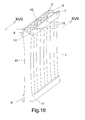
- FIG. 15 is still an embodiment of a lightweight construction carrier with four basic bodies 1,1 ', 1 ", 1"' shown, the riveting of a common stabilizing plate 31 with the basic bodies 1,1 ', 1 ", 1"' allowed.
- eight mutually parallel Doppeistege 39 are provided on the underside of the stabilizing plate 31, which is also present here as a strip-shaped plate, of which two each form a pair. Between the webs 39 of a pair of each one of the base body is 1,1 ', 1 ", 1"' positioned and connected by means of rivets 15 with the stabilizing plate 31.
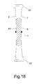
- the main body 1 is provided in its central region, in particular exactly in its center, with a constriction 41, which in reality constitutes a few millimeters, for example between 1 and 5 mm.
- the constriction serves to prevent bending or buckling of the lightweight carrier at particularly high loads. This is done by the constriction 41 specifies a preferred direction in which the, the first metal layer 3 forming trapezoidal sheet will bend or will evade.
- the constriction 41 has a concave shape with the result, so that the bending forces are directed inwardly of the hard foam layer. Since from the other trapezoidal sheet 7 the same force from the other side, also directed inward counteracts, the base body 1 maintains its shape.
- the constriction 41 is best produced by manufacturing technology, for example, by first foaming the middle region with the constriction 41. Then wait a while until the hardening of the foam starts. After reaching a certain degree of hardness, which no longer allows flowability of the material, the two edges are foamed from above or below with a pressure which is so high that a slight widening of the distance between the two trapezoidal sheets 3, 7 takes place.
Landscapes
- Engineering & Computer Science (AREA)
- Architecture (AREA)
- Chemical & Material Sciences (AREA)
- Composite Materials (AREA)
- Civil Engineering (AREA)
- Structural Engineering (AREA)
- Road Paving Structures (AREA)
- Photovoltaic Devices (AREA)
Applications Claiming Priority (1)
| Application Number | Priority Date | Filing Date | Title |
|---|---|---|---|
| DE102009049855A DE102009049855A1 (de) | 2009-10-20 | 2009-10-20 | Leichtbauträger für Photovoltaikanlagen |
Publications (1)
| Publication Number | Publication Date |
|---|---|
| EP2314791A2 true EP2314791A2 (fr) | 2011-04-27 |
Family
ID=43277567
Family Applications (1)
| Application Number | Title | Priority Date | Filing Date |
|---|---|---|---|
| EP10013536A Withdrawn EP2314791A2 (fr) | 2009-10-20 | 2010-10-12 | Une poutre légère |
Country Status (3)
| Country | Link |
|---|---|
| US (1) | US20110089303A1 (fr) |
| EP (1) | EP2314791A2 (fr) |
| DE (1) | DE102009049855A1 (fr) |
Families Citing this family (1)
| Publication number | Priority date | Publication date | Assignee | Title |
|---|---|---|---|---|
| US20150286029A1 (en) * | 2012-09-10 | 2015-10-08 | Bernard Robert Nasr | Reflector supports and methods of manufacture |
Family Cites Families (13)
| Publication number | Priority date | Publication date | Assignee | Title |
|---|---|---|---|---|
| US2101090A (en) * | 1936-04-15 | 1937-12-07 | Roy Lacy | Composite girder construction |
| GB504146A (en) * | 1938-01-27 | 1939-04-20 | Budd Edward G Mfg Co | Improvements in or relating to composite sheet metal structures and methods of fabricating the same |
| CH394567A (it) * | 1962-05-29 | 1965-06-30 | Prodotti Termoplastici Carlo P | Complesso di elementi componibili per la costruzione di pareti perimetrali e/o divisorie di edifici |
| CH406584A (de) * | 1963-02-21 | 1966-01-31 | Hern Geoffrey Benjamin | Bauelement |
| DE1994487U (de) * | 1964-09-30 | 1968-09-26 | Mannesmann Ag | Vollwandtraeger. |
| DE1934292U (de) * | 1965-12-04 | 1966-03-10 | Horst Kassau | Zusammengesetzter traeger. |
| US3405666A (en) * | 1967-02-10 | 1968-10-15 | Sheller Globe Corp | Pallet assembly |
| DE1759382C3 (de) * | 1968-04-26 | 1976-01-08 | Hoesch Werke Ag, 4600 Dortmund | Profiliertes Plattentragwerk |
| DE2933952A1 (de) * | 1979-08-22 | 1981-03-12 | Schmelzer-Bongardt, Almut, 4100 Duisburg | Bauelement. |
| GB8620455D0 (en) * | 1986-08-22 | 1986-10-01 | Nash S | Roofing system |
| WO1994006693A1 (fr) * | 1992-09-17 | 1994-03-31 | Sixty Fifth Calejero Pty. Ltd. | Palette en acier avec couche ondulee support de charge |
| US5619837A (en) * | 1995-07-26 | 1997-04-15 | Disanto; Fabricio N. | Corrugated panel structure |
| CA2648822C (fr) * | 2008-10-20 | 2014-12-09 | Arthur George Paetkau | Panneaux de construction prefabriques et structures, construction, methodes et systemes connexes |
-
2009
- 2009-10-20 DE DE102009049855A patent/DE102009049855A1/de not_active Withdrawn
-
2010
- 2010-10-06 US US12/899,175 patent/US20110089303A1/en not_active Abandoned
- 2010-10-12 EP EP10013536A patent/EP2314791A2/fr not_active Withdrawn
Non-Patent Citations (1)
| Title |
|---|
| None |
Also Published As
| Publication number | Publication date |
|---|---|
| US20110089303A1 (en) | 2011-04-21 |
| DE102009049855A1 (de) | 2011-04-21 |
Similar Documents
| Publication | Publication Date | Title |
|---|---|---|
| EP2653625B1 (fr) | Composant à isolation thermique | |
| DD144176A5 (de) | Verbundtraeger | |
| DE4226742A1 (de) | Verkleidungselement für Böden, Decken, Wände und Fassaden | |
| DE2915460A1 (de) | Palette mit laengstraegerelementen und tragflaechenelementen | |
| DE2727286A1 (de) | Verfahren und vorrichtung zum verbinden flaechenfoermiger bauelemente | |
| EP0059171B1 (fr) | Boulon et canon pour la prise et la transmission d'une force transversale | |
| EP2821561B1 (fr) | Elément de construction en bois et structure composite en bois/béton | |
| DE202006015693U1 (de) | Holz-Beton-Verbundelement | |
| DE202016008552U1 (de) | Ziegelverkleidungssystem | |
| EP2647779B1 (fr) | Support d'angle pour une infrastructure de façade | |
| DE102009003087A1 (de) | Schwerlast-Verteilerplatte | |
| EP2314791A2 (fr) | Une poutre légère | |
| DE19704715C3 (de) | Wärmedämmplatte aus Kunstschaumstoff sowie Verfahren zum Verlegen und Befestigen von Wärmedämmplatten | |
| DE602004010196T2 (de) | Baurahmenprofil | |
| DE2708095A1 (de) | Verfahren und abstandhalter zum befestigen eines verbundelementes an einer tragkonstruktion | |
| DE2950614C2 (de) | Profilträger aus Blech für Trägerdecken aus Stahlbeton und Hohlkörpersteinen | |
| DE102015003338A1 (de) | Holz-Beton-Verbundkonstruktion und Verfahren zu deren Herstellung | |
| EP1972734A1 (fr) | Corps de fixation pour un panneau isolant | |
| DE4341856C2 (de) | Verbundschalung | |
| DE102007004573A1 (de) | Wandbauelement, Verfahren zur Herstellung eines Wandbauelements und ein Ankerbauteil für ein Wandbauelement | |
| EP3546666A1 (fr) | Module de raccordement bois-béton | |
| DE4331698A1 (de) | Hohlwand | |
| AT218220B (de) | Aus Ober- und Untergurt sowie Verbindungsstegen bestehender Träger, insbesondere Binder für Dachkonstruktionen | |
| DE202018003027U1 (de) | Verbindungsstück zur winkeligen Verbindung zweier Bauteile | |
| DE7513823U (de) | Traegerrost zum befestigen von platten, insbesondere von isolierplatten fuer nichttragende trennwaende, falsche decken, dielen o.dgl. |
Legal Events
| Date | Code | Title | Description |
|---|---|---|---|
| PUAI | Public reference made under article 153(3) epc to a published international application that has entered the european phase |
Free format text: ORIGINAL CODE: 0009012 |
|
| AK | Designated contracting states |
Kind code of ref document: A2 Designated state(s): AL AT BE BG CH CY CZ DE DK EE ES FI FR GB GR HR HU IE IS IT LI LT LU LV MC MK MT NL NO PL PT RO RS SE SI SK SM TR |
|
| AX | Request for extension of the european patent |
Extension state: BA ME |
|
| STAA | Information on the status of an ep patent application or granted ep patent |
Free format text: STATUS: THE APPLICATION HAS BEEN WITHDRAWN |
|
| 18W | Application withdrawn |
Effective date: 20130822 |