EP2314791A2 - Lightweight girder - Google Patents
Lightweight girder Download PDFInfo
- Publication number
- EP2314791A2 EP2314791A2 EP10013536A EP10013536A EP2314791A2 EP 2314791 A2 EP2314791 A2 EP 2314791A2 EP 10013536 A EP10013536 A EP 10013536A EP 10013536 A EP10013536 A EP 10013536A EP 2314791 A2 EP2314791 A2 EP 2314791A2
- Authority
- EP
- European Patent Office
- Prior art keywords
- lightweight construction
- profile
- base body
- layer
- lightweight
- Prior art date
- Legal status (The legal status is an assumption and is not a legal conclusion. Google has not performed a legal analysis and makes no representation as to the accuracy of the status listed.)
- Withdrawn
Links
Images


Classifications
-
- E—FIXED CONSTRUCTIONS
- E04—BUILDING
- E04C—STRUCTURAL ELEMENTS; BUILDING MATERIALS
- E04C3/00—Structural elongated elements designed for load-supporting
- E04C3/02—Joists; Girders, trusses, or trusslike structures, e.g. prefabricated; Lintels; Transoms; Braces
- E04C3/29—Joists; Girders, trusses, or trusslike structures, e.g. prefabricated; Lintels; Transoms; Braces built-up from parts of different material, i.e. composite structures
-
- F—MECHANICAL ENGINEERING; LIGHTING; HEATING; WEAPONS; BLASTING
- F24—HEATING; RANGES; VENTILATING
- F24S—SOLAR HEAT COLLECTORS; SOLAR HEAT SYSTEMS
- F24S25/00—Arrangement of stationary mountings or supports for solar heat collector modules
- F24S25/40—Arrangement of stationary mountings or supports for solar heat collector modules using plate-like mounting elements, e.g. profiled or corrugated plates; Plate-like module frames
Definitions
- the invention relates to a lightweight carrier, in particular for use as a support beam for module rails in photovoltaic plant construction with a corrugated base body having a first layer of metal, on which a second layer of hard foam is applied, in turn, from a further layer Metal is applied.
- Such bases are known per se and serve as a roof or wall in buildings, as they are protected by the hard foam layer, e.g. Made of polyurethane, provide a good thermal insulation and at the same time have a satisfactory mechanical strength in order to install larger plates of several square meters can.
- the hard foam layer e.g. Made of polyurethane
- these plates have not been used, since they can not withstand the tensile and compressive forces that occur in their function as a carrier. The curl would be upset, causing the wearer to lose his firmness.
- the present invention has for its object to integrate the known plate structure in a lightweight construction carrier.
- the base body has the shape of an elongated rectangle, on or at the upper and lower longitudinal edge each have a stabilizing rail or that the stabilizing rails are positively incorporated in the upper, or in the lower longitudinal side face of the body.
- the stabilizing rail is a flat profile made of metal or plastic, which is secured laterally on at least one side at the lower and upper longitudinal edge of the base body.
- the flat profile can also be applied directly to the free end face of the base body and there, for example. spot-welded.
- the leg of an angle profile is understood.
- the alternative to form the stabilizing rail as a U-profile made of metal or plastic embrace the two limbs on both sides of the respective longitudinal edge or, in the case of the alternative, are positively embedded in a recess in the frontal surface.
- light metals such as e.g. Aluminum in question and as plastic such high strength, which may be additionally provided with carbon or even made entirely of it.
- the attachment is advantageously carried out so that the flat profile or the legs of the U-profile are riveted to the vertices of several waves of the body. It is clear that the apex of the wave on one side of the body at the opposite side of the wave trough is, if you keep the line of sight. When looking at the respective side, it is then always the vertex on the wave crest which is offered to the observer, to which the attachment means, such as, for example, the rivet, the connection between the body and the stabilizer produces.
- a further increase in stability is achieved when the bottom of only one of the upper and possibly lower U-profiles is poured with a hardening mass.
- the mass consists for example of synthetic resin, concrete or concrete mixed with granite powder, but may also be any suitable substance which is flowable before curing. It should be light within the reasonable cost, such as a body of carbonated carbon impregnated with resin.
- the mass may optionally be mixed with foamed spheres, such as polystyrene balls, which further reduce their weight without losing strength.
- the basic body is any wave-shaped body designed in a broad sense, such as e.g. a trapezoidal field carrier which is corrugated in a trapezoidal shape, a zigzag profile which has a triangular corrugation or a box profile in which the corrugation is rectangular.
- the first layer and the further layer are commercially available structural panels, such as e.g. a trapezoidal sheet, between which the second layer is glued.
- a thickness or thickness for the first and the further layers be between 0.2 mm and 2 mm, in particular between 0.5 mm and 1 mm.
- a variant of the previously described lightweight carrier provides that two parallel base bodies are arranged side by side, whose opposing inner upper and / or lower edge surfaces are each connected to the outside of one of the legs of a arranged between the bodies U-profile made of metal or plastic.
- a slightly more complicated shape provides a wider U-profile strip, on the inside of the left leg of the first base body and on the inside of the right leg of the second body are attached.
- the attachment options described above in connection with single-body solution between body and stabilizer are applicable.
- a plurality (e.g., between 4 and 8) of bodies may also be parallel to each other and may be connected by a common stabilizer bar, which may then also be a wider stripe of e.g. 1 meter wide can be connected.
- the common stabilizing rail is connected to at least the central base bodies only via the end face with the basic bodies.
- a permanently elastic mass such as bitumen
- the permanently elastic mass may be sprayed onto the cured mass or it may be a rubber or rubber tape inserted in the U-profile become.
- one side of the strip must first be laminated with the elastic mass.
- the thickness of the permanently elastic mass should be between 5 mm to 12 mm and the penetration depth of the edge into the elastic mass between 2 mm and 7 mm. It is also the reverse construction possible, in which then the permanently elastic mass is applied directly to the bottom of the U-profile and the longitudinal end face opens there. An additional, hardening layer is then poured onto the permanently elastic layer.
- 1 denotes a main body which is composed of a first metal layer 3, a hard foam layer 5 and a further metal layer 7.
- the main body 1 is cut from a known plate into a strip whose length is a multiple, for example, 5 to 100 times, in particular 10 to 50 times, its width. With a width between 10 cm and 40 cm, the strip can be several meters long.
- the base body is provided with a first and a second stabilizing means in the form of a first and second flat strip 9, 11, which may in particular be a flat iron.
- flat strips 9 ', 11' are located laterally near the lower edge of the main body 1.
- the flat strips 9, 11 are connected to the main body 1 by means of rivets 15.
- the rivets 15 are provided in the vicinity of the apex of the wave-shaped base support 1, ie in the example shown a trapezoidal sheet on the outer narrow surfaces of the trapezoidal base. At a pressure and bending load distribute the flat belts 9.11 the forces uniformly over the length of the strip and prevent in particular a deflection or compression of the main body. 1
- FIGS. 5 to 7 correspond to the FIGS. 2 to 4 with the difference that instead of two flat belts 9, 11 fastened on both sides, a U-profile 17 is provided, whose two legs are likewise designated by 9 or 11 and whose bottom or base is designated by 19.
- the FIG. 5 is a view of the lightweight construction, in which the hidden components are shown by dashed lines.
- the U-profile 17 is placed on the end face 13, where it is either attached to the rivets 15 on the base body 1 and / or glued there.
- FIG. 8 equals to FIG. 6 with the difference that the end face 13 does not extend to the bottom of the U-profile 17, but in an elastic layer 21, for example of bitumen, embedded, which in turn rests on a potting layer 23 of a hard material, such as concrete. It is also an embodiment makes sense, which has only the casting layer 23 made of concrete to stabilize the U-profile 21, in which case the end face 13 again ends before the potting layer 23 to initiate no pressure or Buchspitzen in the base body 1 from the concrete mass. Likewise, the potting layer 23 can be completely dispensed with, and the end face 13 ends within the remaining elastic layer 21.
- FIGS. 9 and 10 is ever a variant with two basic bodies 1,1 'shown, both of which are the same and analogous to the base body 1 described above.
- the basic bodies 1 and 1 ' run parallel to one another and are connected by means of a wider U-profile 17' than is required in the single-body variant.
- the FIG. 9 shows a U-profile 17 ', which surrounds the outer edges or edges of the base body 1,1', so that the edges come to rest on the inner sides of the U-legs 9,11.
- the reverse arrangement is in the FIG. 10 shown.
- FIG. 11 is an embodiment of a lightweight construction carrier with a positive, integrated into the upper, longitudinal side end face 13 of the base body 1 round profile 27 shown as a stabilizing rail.
- the round profile 27 is a solid steel wire which is inserted into a recess 25 which has been milled into the end face 13.
- the round profile 27 is frictionally fixed in the recess with the base body 1, for example by means of an adhesive or a weld.
- the lower, not shown side is stabilized in the same way. This results in a good strength of the lightweight carrier with a small weight.
- FIG 12 1 shows an embodiment of a lightweight construction carrier with a positive U-profile 17 "'integrated into the upper, longitudinal-side end face 13 of the main body 1.
- the recess 25 ' also runs through the hard foam layer 5, so that in each case a rectangular cross-section groove is formed, in which the two legs of the U-profile 17 "' lie positively , Positive locking means in this case that the basic shape of the body 1 remains unchanged and there are no protruding parts of the stabilizing rail.
- FIG. 13 shows a lightweight carrier with four basic bodies 1,1 ', 1 ", 1'” and a common, on its underside form-fitting manner in the longitudinal end faces 13,13 ', 13 “, 13"' of the associated base body 1 ', 1 ", 1
- the stabilizing plate 31 is provided on its underside with four parallel projections 33, 33 ', 33 “, 33”', in the assembly of the lightweight construction carrier in four opposing grooves 35,35 ', 35 ", 35”' in the basic bodies 1,1 ', 1 "and 1'” positioned and glued there.
- FIG. 14 A further embodiment of a lightweight construction carrier with four basic bodies 1, 1 ', 1 ", 1”' and a common, form-fitting manner on the end surfaces 13, 13 ', 13 ", 13"' of the basic bodies 1, 1 ', 1 ", 1'”connected stabilizing plate 31 is in the FIG. 14 shown.
- This embodiment is the technically most modest among the multi-basic body variants, because the stabilizing plate 31 is a flat, cut into a strip steel plate, on its underside with the end faces 13,13 ', 13 ", 13"' of the base body 1, 1 ', 1 ", 1'” is glued by means of an adhesive layer 37.
- FIG. 15 is still an embodiment of a lightweight construction carrier with four basic bodies 1,1 ', 1 ", 1"' shown, the riveting of a common stabilizing plate 31 with the basic bodies 1,1 ', 1 ", 1"' allowed.
- eight mutually parallel Doppeistege 39 are provided on the underside of the stabilizing plate 31, which is also present here as a strip-shaped plate, of which two each form a pair. Between the webs 39 of a pair of each one of the base body is 1,1 ', 1 ", 1"' positioned and connected by means of rivets 15 with the stabilizing plate 31.
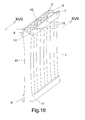
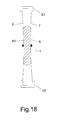
- the main body 1 is provided in its central region, in particular exactly in its center, with a constriction 41, which in reality constitutes a few millimeters, for example between 1 and 5 mm.
- the constriction serves to prevent bending or buckling of the lightweight carrier at particularly high loads. This is done by the constriction 41 specifies a preferred direction in which the, the first metal layer 3 forming trapezoidal sheet will bend or will evade.
- the constriction 41 has a concave shape with the result, so that the bending forces are directed inwardly of the hard foam layer. Since from the other trapezoidal sheet 7 the same force from the other side, also directed inward counteracts, the base body 1 maintains its shape.
- the constriction 41 is best produced by manufacturing technology, for example, by first foaming the middle region with the constriction 41. Then wait a while until the hardening of the foam starts. After reaching a certain degree of hardness, which no longer allows flowability of the material, the two edges are foamed from above or below with a pressure which is so high that a slight widening of the distance between the two trapezoidal sheets 3, 7 takes place.
Abstract
Description
Die Erfindung bezieht sich auf einen Leichtbauträger, insbesondere für den Einsatz als Trägerbalken für Modulschienen im Photovoltaik-Anlagenbau mit einem gewellten Grundkörper, der eine erste Schicht aus Metall aufweist, auf welche eine zweite Schicht aus Hartschaum aufgebracht ist, auf welche wiederum eine weitere Schicht aus Metall aufgebracht ist.The invention relates to a lightweight carrier, in particular for use as a support beam for module rails in photovoltaic plant construction with a corrugated base body having a first layer of metal, on which a second layer of hard foam is applied, in turn, from a further layer Metal is applied.
Solche Grundkörper sind per se bekannt und dienen als Dach oder Wand bei Gebäuden, da sie durch die Hartschaumschicht, z.B. aus Polyurethan, eine gute thermische Isolierung bereitstellen und zugleich eine zufrieden stellende mechanische Festigkeit aufweisen, um auch größere Platten von mehreren Quadratmetern installieren zu können. Als Träger haben diese Platten bisher keine Anwendung erfahren, da sie den Zug- und Druckkräften, die bei ihrer Funktion als Träger auftreten, nicht standhalten können. Die Wellung würde gestaucht werden, womit der Träger seine Festigkeit verliert.Such bases are known per se and serve as a roof or wall in buildings, as they are protected by the hard foam layer, e.g. Made of polyurethane, provide a good thermal insulation and at the same time have a satisfactory mechanical strength in order to install larger plates of several square meters can. As a carrier, these plates have not been used, since they can not withstand the tensile and compressive forces that occur in their function as a carrier. The curl would be upset, causing the wearer to lose his firmness.
Insbesondere bei Photovoltaikgroßanlagen kommen zur Zeit als Träger Holzbalken zum Einsatz, die zum einen relativ schwer und damit unhandlich zu montieren und zum anderen teuer sind. Die Erfindung geht aus von der Überlegung, dass die bekannte Platte von geringem spezifischem Gewicht so durch Anbauteile modifiziert werden müsste, dass sie als Basiskomponente für einen Träger dienen kann. Entsprechend liegt vorliegender Erfindung die Aufgabe zugrunde, die bekannte Plattenstruktur in einen Leichtbauträger zu integrieren.Especially in large photovoltaic systems come at the time as a carrier wooden beams are used, which are relatively difficult and thus difficult to assemble and expensive for another. The invention is based on the consideration that the known plate of low specific weight would have to be modified by attachments so that it can serve as a base component for a carrier. Accordingly, the present invention has for its object to integrate the known plate structure in a lightweight construction carrier.
Diese Aufgabe wird erfindungsgemäß dadurch gelöst, dass der Grundkörper die Form eines langgestreckten Rechtecks aufweist, auf oder an dessen oberem und unterem längsseitigen Rand jeweils eine Stabilisierungsschiene verläuft oder dass die Stabilisierungsschienen formschlüssig in die obere, beziehungsweise in die untere längsseitige Stirnfläche der Grundkörpers eingearbeitet sind.This object is achieved in that the base body has the shape of an elongated rectangle, on or at the upper and lower longitudinal edge each have a stabilizing rail or that the stabilizing rails are positively incorporated in the upper, or in the lower longitudinal side face of the body.
Da die Stauchung unter Last durch einen Verlust der Wellenstruktur entsteht, wird durch die Stabilisierungsschiene eben diese Wellenstruktur gestärkt und ein Einknicken oder eine Stauchung tritt erst bei erheblich höheren Kräften auf als wenn keine Stabilisierungsschiene vorhanden ist.Since the compression under load caused by a loss of the wave structure is stabilized by the stabilizing rail just this wave structure and A buckling or compression only occurs at considerably higher forces than if no stabilizer rail is present.
Im einfachsten Fall ist die Stabilisierungsschiene ein Flachprofil aus Metall oder Kunststoff, welches jeweils am unteren und oberen längsseitigen Rand des Grundkörpers auf zumindest einer Seite seitlich befestigt ist. Das Flachprofil kann auch direkt auf die freie Stirnseite des Grundkörpers aufgebracht und dort z.B. punktverschweißt werden. Als Flachprofil wird dabei auch der Schenkel eines Winkelprofils verstanden. Etwas aufwendiger ist die Alternative, die Stabilisierungsschiene als ein U-Profil aus Metall oder Kunststoff auszubilden, dessen beiden Schenkel beidseitig den jeweiligen längsseitigen Rand umgreifen oder, im Falle der Alternative, in eine Aussparung in der stirnseitigen Fläche formschlüssig eingebettet sind. Als Metall kommen dabei insbesondere Leichtmetalle wie z.B. Aluminium infrage und als Kunststoff solche mit hoher Festigkeit, die eventuell zusätzlich noch mit Karbon versehen sind oder sogar ganz daraus bestehen. Die Befestigung erfolgt zweckmäßiger Weise so, dass das Flachprofil bzw. die Schenkel des U-Profils an den Scheitelpunkten mehrerer Wellen des Grundkörpers vernietet sind. Dabei ist klar, dass der Scheitelpunkt der Welle auf einer Seite des Grundkörpers bei der gegenüberliegenden Seite das Wellental ist, wenn man die Blickrichtung beibehält. Bei Blick auf die jeweilige Seite ist es dann immer der sich dem Betrachter bietende Scheitelpunkt am Wellenberg, an dem das Befestigungsmittel, wie z.B. die Niete, die Verbindung zwischen dem Grundkörper und dem Stabilisierungsmittel herstellt.In the simplest case, the stabilizing rail is a flat profile made of metal or plastic, which is secured laterally on at least one side at the lower and upper longitudinal edge of the base body. The flat profile can also be applied directly to the free end face of the base body and there, for example. spot-welded. As a flat profile while the leg of an angle profile is understood. Somewhat more expensive is the alternative to form the stabilizing rail as a U-profile made of metal or plastic, embrace the two limbs on both sides of the respective longitudinal edge or, in the case of the alternative, are positively embedded in a recess in the frontal surface. In particular, light metals such as e.g. Aluminum in question and as plastic such high strength, which may be additionally provided with carbon or even made entirely of it. The attachment is advantageously carried out so that the flat profile or the legs of the U-profile are riveted to the vertices of several waves of the body. It is clear that the apex of the wave on one side of the body at the opposite side of the wave trough is, if you keep the line of sight. When looking at the respective side, it is then always the vertex on the wave crest which is offered to the observer, to which the attachment means, such as, for example, the rivet, the connection between the body and the stabilizer produces.
Eine weitere Erhöhung der Stabilität wird erzielt, wenn der Boden nur eines der oberen und ggf. unteren U-Profile mit einer aushärtenden Masse ausgegossen wird. Die Masse besteht beispielsweise aus Kunstharz, Beton oder Beton mit beigemischtem Granitpulver, kann aber auch jedwede geeignete Substanz sein, die vor dem Aushärten fließfähig ist. Sie sollte im Rahmen der vertretbaren Kosten leicht sein, wie z.B. ein Körper aus in Gießharz getränktem Karbonpulver. Die Masse kann gegebenenfalls mit aufgeschäumten Kugeln, wie Styroporkugeln, versetzt sein, die ihr Gewicht weiter reduzieren, ohne an Festigkeit einzubüßen.A further increase in stability is achieved when the bottom of only one of the upper and possibly lower U-profiles is poured with a hardening mass. The mass consists for example of synthetic resin, concrete or concrete mixed with granite powder, but may also be any suitable substance which is flowable before curing. It should be light within the reasonable cost, such as a body of carbonated carbon impregnated with resin. The mass may optionally be mixed with foamed spheres, such as polystyrene balls, which further reduce their weight without losing strength.
Als Grundkörper eignet sich jeder in breitem Sinne ausgelegter wellenförmiger Körper wie z.B. ein Trapezfeldträger, der trapezförmig gewellt ist, ein Zickzack-Profil welches eine dreiecksförmige Wellung aufweist oder ein Kastenprofil, bei dem die Wellung rechteckförmig ist. Bei allen Ausführungen gilt, dass die erste Schicht und die weitere Schicht handelsübliche Strukturplatten, wie z.B. ein Trapezblech sind, zwischen denen die zweite Schicht verklebt ist. Für die Strukturplatten (z.B. Trapezblech) gilt, dass eine Stärke oder Dicke für die erste und die weitere Schicht zwischen 0,2 mm und 2 mm, insbesondere zwischen 0,5 mm und 1 mm sinnvoll ist. Bei Einsatz der Träger zu anderen als dem vorgesehenen Zweck bei Photovoltaikanlage können auch dickere und schwerere Schichten Verwendung finden.The basic body is any wave-shaped body designed in a broad sense, such as e.g. a trapezoidal field carrier which is corrugated in a trapezoidal shape, a zigzag profile which has a triangular corrugation or a box profile in which the corrugation is rectangular. In all embodiments, the first layer and the further layer are commercially available structural panels, such as e.g. a trapezoidal sheet, between which the second layer is glued. For the structural plates (e.g., trapezoidal sheet), it is reasonable that a thickness or thickness for the first and the further layers be between 0.2 mm and 2 mm, in particular between 0.5 mm and 1 mm. When using the carrier for other than the intended purpose in photovoltaic system and thicker and heavier layers can be used.
Eine Variante des zuvor beschriebenen Leichtbauträgers sieht vor, dass zwei parallel verlaufende Grundkörper nebeneinander angeordnet sind, deren sich gegenüberliegende innere obere und/oder untere Randflächen mit jeweils der Außenseite eines der Schenkel eines zwischen den Grundkörpern angeordneten U-Profils aus Metall oder Kunststoff verbunden sind. Eine etwas kompliziertere Form sieht eine breitere U-Profilleiste vor, an dessen Innenseite des linken Schenkels der erste Grundkörper und an dessen Innenseite des rechten Schenkels der zweite Grundkörper befestigt sind. Auch hier sind die zuvor in Zusammenhang mit Ein-Grundkörper-Lösung beschriebenen Befestigungsmöglichkeiten zwischen Grundkörper und Stabilisierungsmittel anwendbar. Bei großen zu überbrückenden Spannweiten kann auch eine Vielzahl (z.B. zwischen 4 und acht) von Grundkörpern parallel zueinander verlaufen und durch eine gemeinsame Stabilisierungsschiene, die dann auch ein breiterer Streifen von z.B. 1 Meter Breite sein kann, verbunden werden. Dabei ist die gemeinsame Stabilisierungsschiene an zumindest den mittleren Grundkörpern nur über die Stirnfläche mit den Grundkörpern verbunden.A variant of the previously described lightweight carrier provides that two parallel base bodies are arranged side by side, whose opposing inner upper and / or lower edge surfaces are each connected to the outside of one of the legs of a arranged between the bodies U-profile made of metal or plastic. A slightly more complicated shape provides a wider U-profile strip, on the inside of the left leg of the first base body and on the inside of the right leg of the second body are attached. Again, the attachment options described above in connection with single-body solution between body and stabilizer are applicable. For large spans to be bridged, a plurality (e.g., between 4 and 8) of bodies may also be parallel to each other and may be connected by a common stabilizer bar, which may then also be a wider stripe of e.g. 1 meter wide can be connected. In this case, the common stabilizing rail is connected to at least the central base bodies only via the end face with the basic bodies.
Um Spannungsspitzen an den Krafteinleitungsstellen, d.h. an den Rändern des Grundkörpers abzumildern, ist es vorgesehen, auf der ausgehärteten Masse eine dauerelastische Masse, wie z.B. Bitumen aufzubringen, in welche der oder beide längsseitigen Ränder des oder der Grundkörper teilweise eingebettet sind. Die dauerelastische Masse kann auf die ausgehärtete Masse aufgesprüht sein oder es kann ein Gummi- oder Kautschukband in das U-Profil eingelegt werden. Bei der Flachband bzw. Flacheisenlösung ist eine Seite des Bandes zuvor mit der elastischen Masse zu kaschieren. Die Dicke der dauerelastischen Masse sollte zwischen 5 mm bis 12 mm liegen und die Eindringtiefe des Randes in die elastische Masse zwischen 2 mm und 7 mm. Es ist auch der umgekehrte Aufbau möglich, bei dem dann die dauerelastische Masse direkt auf den Boden des U-Profils aufgetragen ist und die längsseitige Stirnfläche dort mündet. Eine zusätzliche, aushärtende Schicht ist dann auf die dauerelastische Schicht gegossen.In order to mitigate stress peaks at the force introduction points, ie at the edges of the body, it is provided to apply a permanently elastic mass, such as bitumen, into which the one or both longitudinal edges of the body or bodies are partially embedded on the hardened mass. The permanently elastic mass may be sprayed onto the cured mass or it may be a rubber or rubber tape inserted in the U-profile become. In the case of the flat strip or flat iron solution, one side of the strip must first be laminated with the elastic mass. The thickness of the permanently elastic mass should be between 5 mm to 12 mm and the penetration depth of the edge into the elastic mass between 2 mm and 7 mm. It is also the reverse construction possible, in which then the permanently elastic mass is applied directly to the bottom of the U-profile and the longitudinal end face opens there. An additional, hardening layer is then poured onto the permanently elastic layer.
Weitere Vorteile und Ausgestaltungen der Erfindung ergeben sich aus der Beschreibung der Ausführungsbeispiele anhand der Figuren. Es zeigen:
- Fig. 1
- eine perspektivische Schrägaufsicht auf einen Leichtbauträger nach der Erfindung;
- Fig. 2
- einen Schnitt entlang der Linie II-II der
Fig. 1 ; - Fig. 3
- einen Schnitt entlang der Linie III-III der
Figur 2 ; - Fig. 4
- einen Schnitt entlang der Linie IV-IV der
Figur 2 - Fig. 5
- eine Aufsicht auf den Träger nach
Figur 1 - Fig. 6
- einen Schnitt entlang der Linie VI-VI der
Figur 5 - Fig. 7
- einen Schnitt entlang der Linie VII-VII der
Figur 5 - Fig. 8
- einen Schnitt entsprechend der
Figur 6 mit Vergussmasse im U- Profilgrund; - Fig. 9
- einen Leichtbauträger mit zwei Grundelementen und außen liegendem U-Profil;
- Fig.10
- einen Leichtbauträger mit zwei Grundelementen und innen liegendem U-Profil;
- Fig.11, 11a
- eine erste Ausführungsform eines Leichtbauträgers mit formschlüssig in die längsseitige Stirnfläche des Grundkörpers integriertem Rundeisen als Stabilisierungsschiene;
- Fig.12
- eine zweite Ausführungsform eines Leichtbauträgers mit formschlüssig in die längsseitige Stirnflächen des Grundkörpers integrierter Stabilisierungsschiene;
- Fig.13
- eine Ausführungsform eines Leichtbauträgers mit vielen Grundkörpern und eine gemeinsame, auf ihrer Unterseite formschlüssig in die längsseitigen Stirnflächen der Grundkörper integrierte Stabilisierungsschiene;
- Fig.14
- eine Ausführungsform eines Leichtbauträgers mit vielen Grundkörpern und eine gemeinsame, formschlüssig an den Stirnflächen der Grundkörper verbundene Stabilisierungsschiene;
- Fig.15
- eine Ausführungsform eines Leichtbauträgers mit vielen Grundkörpern und mit einer gemeinsamen, an den oberen Rändern der Grundkörper vernieteten Stabilisierungsschiene;
- Fig.16
- eine perspektivische Ansicht einer weiteren Ausführungsform mit einer Einschnürung; und
- Fig. 17
- eine Profilansicht zur Ausführungsform nach der
Figur 16 .
- Fig. 1
- a perspective oblique view of a lightweight carrier according to the invention;
- Fig. 2
- a section along the line II-II of
Fig. 1 ; - Fig. 3
- a section along the line III-III of
FIG. 2 ; - Fig. 4
- a section along the line IV-IV of
FIG. 2 - Fig. 5
- a view of the carrier after
FIG. 1 with a U-profile instead of two flat belts; - Fig. 6
- a section along the line VI-VI of
FIG. 5 ; - Fig. 7
- a section along the line VII-VII of
FIG. 5 ; - Fig. 8
- a cut according to the
FIG. 6 with potting compound in U-profile ground; - Fig. 9
- a lightweight carrier with two basic elements and outer U-profile;
- Figure 10
- a lightweight carrier with two basic elements and inside U-profile;
- 11, 11a
- a first embodiment of a lightweight construction carrier with an integrally integrated in the longitudinal side face of the body round bar as a stabilizing rail;
- Figure 12
- a second embodiment of a lightweight carrier with positively integrated in the longitudinal end faces of the body stabilizing rail;
- Figure 13
- an embodiment of a lightweight construction carrier with many basic bodies and a common, on its underside form-fitting integrated in the longitudinal end faces of the base stabilizing rail;
- Figure 14
- an embodiment of a lightweight construction carrier with many basic bodies and a common, positively connected to the end faces of the base body stabilizing rail;
- Figure 15
- an embodiment of a lightweight construction carrier with many basic bodies and with a common, riveted to the upper edges of the base body stabilizing rail;
- Figure 16
- a perspective view of another embodiment with a constriction; and
- Fig. 17
- a profile view of the embodiment of the
FIG. 16 ,
In den Figuren ist mit 1 ein Grundkörper bezeichnet, der sich aus einer ersten Metallschicht 3, einer Hartschaumschicht 5 und einer weiteren Metallschicht 7 zusammensetzt. Der Grundkörper 1 ist aus einer an sich bekannten Platte zu einem Streifen geschnitten, dessen Länge ein Vielfaches, z.B. das 5- bis 100-fache, insbesondere das 10- bis 50-fache, seiner Breite beträgt. Bei einer Breite zwischen 10 cm und 40 cm kann der Streifen entsprechend mehrere Meter lang sein. Am seitlichen Rand seines oberen Endes ist der Grundkörper mit einem ersten und einem zweiten Stabilisierungsmittel in Form eines ersten und zweiten Flachbandes 9,11, was insbesondere ein Flacheisen sein kann, versehen. Analog befinden sich Flachbänder 9',11' seitlich in der Nähe des unteren Randes des Grundkörpers 1. Anstelle von zwei Flachbändern 9,11 ist auch ein einziges Flachband 9 ausreichend, insbesondere, wenn es unmittelbar auf die Stirnfläche 13 des Grundkörpers aufgebracht und dort befestigt ist. In der gezeigten Variante sind die Flachbänder 9,11 mittels Nieten 15 mit dem Grundkörper 1 verbunden. Die Nieten 15 sind in der Nähe des Scheitelpunkts des wellenförmigen Grundträgers 1 vorgesehen, d.h. im gezeigten Beispiel eines Trapezbleches an den außen liegenden schmalen Flächen des Trapezgrundes. Bei einer Druck- und Biegebelastung verteilen die Flachbänder 9,11 die Kräfte gleichmäßig über die Länge des Streifens und verhindern insbesondere eine Durchbiegung oder Stauchung des Grundkörpers 1.In the figures, 1 denotes a main body which is composed of a
In den Schnittfiguren 2 bis 4 ist obige Konstruktion noch mal aus anderer Sicht gezeigt, wobei die gleichen Bezugszeichen verwendet wurden.In the sectional figures 2 to 4, the above construction is shown again from another point of view, using the same reference numerals.
Die
Die
In den
In der
In der
Die Ausführungsform der
Eine weitere Ausführungsform eines Leichtbauträgers mit vier Grundkörpern 1,1',1 ",1 "' und einer gemeinsamen, formschlüssig an den Stirnflächen 13,13',13",13"' der Grundkörper 1,1',1",1'" verbundener Stabilisierungsplatte 31 ist in der
In der
Schließlich ist noch in den
Die Einschnürung 41 wird am besten fertigungstechnisch erzeugt, indem z.B. zunächst der mittlere Bereich mit der Einschnürung 41 ausgeschäumt wird. Dann wird eine Zeit lang abgewartet, bis die Härtung des Schaums einsetzt. Nach Erreichen eines gewissen Härtegrads, der keine Fließfähigkeit des Materials mehr zulässt, werden die beiden Ränder von oben bzw. unten mit einem Druck aufgeschäumt, der so hoch bemessen ist, dass eine geringfügige Aufweitung des Abstands zwischen den beiden Trapezblechen 3,7 erfolgt.The
Es wird darauf hingewiesen, dass alle zu einer Variante beschriebenen Ausführungen, wie z.B. das Einbetten in die Stirnfläche 13, Vernietung, Lage des Stabilisierungsmittels, Einschnürung 41 etc. auch auf die anderen Varianten anwendbar sind, soweit es in der Beschreibung nicht ausdrücklich ausgeschlossen wurde. Außerdem kann eine Mischung der Varianten derart erfolgen, dass bei ein und demselben Leichtbauträger an einem Rand eine andere Variante gewählt wird als am anderen Rand. Dabei bleibt es erforderlich, dass immer beide, also der obere und der untere Rand mit einer Stabilisierungsschiene versehen sind.It should be noted that all embodiments described for a variant, such as the embedding in the
- 1,1',1",1"'1,1 ', 1 ", 1"'
- Grundkörperbody
- 33
- erste Metallschichtfirst metal layer
- 55
- HartschaumschichtRigid foam layer
- 77
- weitere Metallschichtanother metal layer
- 99
- erstes Flachbandfirst flat band
- 1111
- zweites Flachbandsecond flat band
- 13,13',13",13"'13,13 ', 13 ", 13"'
- Stirnflächeface
- 1515
- Nietenrivet
- 17,17',17"17,17 ', 17 "
- U-ProfileU-profiles
- 17"'17 " '
- integriertes U-Profilintegrated U-profile
- 1919
- Bodenground
- 2121
- elastische Schichtelastic layer
- 2323
- Vergussschichtcast layer
- 2525
- Rundnutround slot
- 2727
- Rundprofilround profile
- 2929
- Betonbettconcrete bed
- 3131
- StabilisierungsplattenstreifenStabilizing plate strips
- 33,33',33",33"'33,33 ', 33 ", 33"'
- Vorsprunghead Start
- 35,35',35",35"'35,35 ', 35 ", 35"'
- Nutgroove
- 3737
- Klebeschichtadhesive layer
- 3939
- Doppelstegdouble bridge
- 4141
- Einschnürungconstriction
Claims (15)
Applications Claiming Priority (1)
| Application Number | Priority Date | Filing Date | Title |
|---|---|---|---|
| DE102009049855A DE102009049855A1 (en) | 2009-10-20 | 2009-10-20 | Lightweight developer for photovoltaic systems |
Publications (1)
| Publication Number | Publication Date |
|---|---|
| EP2314791A2 true EP2314791A2 (en) | 2011-04-27 |
Family
ID=43277567
Family Applications (1)
| Application Number | Title | Priority Date | Filing Date |
|---|---|---|---|
| EP10013536A Withdrawn EP2314791A2 (en) | 2009-10-20 | 2010-10-12 | Lightweight girder |
Country Status (3)
| Country | Link |
|---|---|
| US (1) | US20110089303A1 (en) |
| EP (1) | EP2314791A2 (en) |
| DE (1) | DE102009049855A1 (en) |
Families Citing this family (1)
| Publication number | Priority date | Publication date | Assignee | Title |
|---|---|---|---|---|
| AU2013313725A1 (en) * | 2012-09-10 | 2015-04-30 | Tiger Profiles and Insulation LLC | Improvements to reflector supports and methods of manufacture |
Family Cites Families (13)
| Publication number | Priority date | Publication date | Assignee | Title |
|---|---|---|---|---|
| US2101090A (en) * | 1936-04-15 | 1937-12-07 | Roy Lacy | Composite girder construction |
| GB504146A (en) * | 1938-01-27 | 1939-04-20 | Budd Edward G Mfg Co | Improvements in or relating to composite sheet metal structures and methods of fabricating the same |
| CH394567A (en) * | 1962-05-29 | 1965-06-30 | Prodotti Termoplastici Carlo P | Complex of modular elements for the construction of perimeter walls and / or partitions of buildings |
| CH406584A (en) * | 1963-02-21 | 1966-01-31 | Hern Geoffrey Benjamin | Component |
| DE1994487U (en) * | 1964-09-30 | 1968-09-26 | Mannesmann Ag | SOLID WALL BEAM. |
| DE1934292U (en) * | 1965-12-04 | 1966-03-10 | Horst Kassau | COMPOSITE CARRIER. |
| US3405666A (en) * | 1967-02-10 | 1968-10-15 | Sheller Globe Corp | Pallet assembly |
| DE1759382C3 (en) * | 1968-04-26 | 1976-01-08 | Hoesch Werke Ag, 4600 Dortmund | Profiled plate structure |
| DE2933952A1 (en) * | 1979-08-22 | 1981-03-12 | Schmelzer-Bongardt, Almut, 4100 Duisburg | Solar heat conveying composite wall or roof panel - has ducts linking cavities between thin plates forming trapezoid profiled cover |
| GB8620455D0 (en) * | 1986-08-22 | 1986-10-01 | Nash S | Roofing system |
| EP0660791A4 (en) * | 1992-09-17 | 1997-01-08 | Sixty Fifth Calejero Pty Ltd | Steel pallet with corrugated load bearing layer. |
| US5619837A (en) * | 1995-07-26 | 1997-04-15 | Disanto; Fabricio N. | Corrugated panel structure |
| US8033065B2 (en) * | 2008-10-20 | 2011-10-11 | Arthur George Paetkau | Prefabricated building panels and structures, building, methods and systems relating to same |
-
2009
- 2009-10-20 DE DE102009049855A patent/DE102009049855A1/en not_active Withdrawn
-
2010
- 2010-10-06 US US12/899,175 patent/US20110089303A1/en not_active Abandoned
- 2010-10-12 EP EP10013536A patent/EP2314791A2/en not_active Withdrawn
Non-Patent Citations (1)
| Title |
|---|
| None |
Also Published As
| Publication number | Publication date |
|---|---|
| DE102009049855A1 (en) | 2011-04-21 |
| US20110089303A1 (en) | 2011-04-21 |
Similar Documents
| Publication | Publication Date | Title |
|---|---|---|
| EP2653625B1 (en) | Thermally insulating component | |
| DD144176A5 (en) | VERBUNDTRAEGER | |
| DE4226742A1 (en) | Cladding element for floors, ceilings, walls and facades | |
| DE2915460A1 (en) | PALLET WITH SPRING ELEMENTS AND WING PANEL ELEMENTS | |
| DE2727286A1 (en) | METHOD AND DEVICE FOR CONNECTING AREA-SHAPED COMPONENTS | |
| DE3636069A1 (en) | COMPOSED BARS | |
| EP0059171B1 (en) | Dowel and sleeve for the absorption and transfer of a shearing force | |
| EP2821561B1 (en) | Wooden structural part and composite wood-concrete structure | |
| DE202006015693U1 (en) | Wood-concrete connecting unit for use in building construction, has slab and support units connected with each other by connection unit that is embedded in slab unit, where slab unit is made of concrete and support unit is made of wood | |
| DE202016008552U1 (en) | Brick cladding system | |
| EP2647779B1 (en) | Angle bracket for a façade substructure | |
| DE102009003087A1 (en) | Heavy duty distribution plate for use as e.g. support plate between supporting pistons of crane and bottom areas, has interface layer whose predominant part is formed by chambers with walls arranged parallel to direction of normal surface | |
| EP2314791A2 (en) | Lightweight girder | |
| DE19704715C3 (en) | Thermal insulation board made of plastic foam and method for laying and fastening thermal insulation boards | |
| DE602004010196T2 (en) | Building frame profile | |
| DE2708095A1 (en) | PROCEDURE AND SPACER FOR FASTENING A COMPOSITE ELEMENT TO A SUPPORTING STRUCTURE | |
| DE2950614C2 (en) | Profile beams made of sheet metal for beam ceilings made of reinforced concrete and hollow blocks | |
| DE102015003338A1 (en) | Wood-concrete composite construction and method for its production | |
| EP1972734A1 (en) | Retaining body for an insulating board | |
| DE4341856C2 (en) | Composite formwork | |
| DE102007004573A1 (en) | Wall component for use as area closure component in industrial building, has connecting units extending over inner and outer layers and another layer, and anchor component extending from layer into inner and outer layers | |
| EP3546666A1 (en) | Wood concrete compound construction set | |
| DE4331698A1 (en) | Hollow wall | |
| AT218220B (en) | Beams consisting of upper and lower chords as well as connecting webs, in particular girders for roof structures | |
| DE202018003027U1 (en) | Connector for the angular connection of two components |
Legal Events
| Date | Code | Title | Description |
|---|---|---|---|
| PUAI | Public reference made under article 153(3) epc to a published international application that has entered the european phase |
Free format text: ORIGINAL CODE: 0009012 |
|
| AK | Designated contracting states |
Kind code of ref document: A2 Designated state(s): AL AT BE BG CH CY CZ DE DK EE ES FI FR GB GR HR HU IE IS IT LI LT LU LV MC MK MT NL NO PL PT RO RS SE SI SK SM TR |
|
| AX | Request for extension of the european patent |
Extension state: BA ME |
|
| STAA | Information on the status of an ep patent application or granted ep patent |
Free format text: STATUS: THE APPLICATION HAS BEEN WITHDRAWN |
|
| 18W | Application withdrawn |
Effective date: 20130822 |