EP2313218B1 - Verfahren und vorrichtung zur herstellung eines aus plastischer masse bestehenden kreiszylindrischen körpers mit innenliegenden wendelförmigen ausnehmungen - Google Patents
Verfahren und vorrichtung zur herstellung eines aus plastischer masse bestehenden kreiszylindrischen körpers mit innenliegenden wendelförmigen ausnehmungen Download PDFInfo
- Publication number
- EP2313218B1 EP2313218B1 EP09779827A EP09779827A EP2313218B1 EP 2313218 B1 EP2313218 B1 EP 2313218B1 EP 09779827 A EP09779827 A EP 09779827A EP 09779827 A EP09779827 A EP 09779827A EP 2313218 B1 EP2313218 B1 EP 2313218B1
- Authority
- EP
- European Patent Office
- Prior art keywords
- rotation
- friction surface
- axis
- cylindrical body
- surface arrangement
- Prior art date
- Legal status (The legal status is an assumption and is not a legal conclusion. Google has not performed a legal analysis and makes no representation as to the accuracy of the status listed.)
- Active
Links
Images
Classifications
-
- B—PERFORMING OPERATIONS; TRANSPORTING
- B21—MECHANICAL METAL-WORKING WITHOUT ESSENTIALLY REMOVING MATERIAL; PUNCHING METAL
- B21B—ROLLING OF METAL
- B21B1/00—Metal-rolling methods or mills for making semi-finished products of solid or profiled cross-section; Sequence of operations in milling trains; Layout of rolling-mill plant, e.g. grouping of stands; Succession of passes or of sectional pass alternations
- B21B1/16—Metal-rolling methods or mills for making semi-finished products of solid or profiled cross-section; Sequence of operations in milling trains; Layout of rolling-mill plant, e.g. grouping of stands; Succession of passes or of sectional pass alternations for rolling wire rods, bars, merchant bars, rounds wire or material of like small cross-section
-
- B—PERFORMING OPERATIONS; TRANSPORTING
- B21—MECHANICAL METAL-WORKING WITHOUT ESSENTIALLY REMOVING MATERIAL; PUNCHING METAL
- B21K—MAKING FORGED OR PRESSED METAL PRODUCTS, e.g. HORSE-SHOES, RIVETS, BOLTS OR WHEELS
- B21K5/00—Making tools or tool parts, e.g. pliers
- B21K5/02—Making tools or tool parts, e.g. pliers drilling-tools or other for making or working on holes
- B21K5/04—Making tools or tool parts, e.g. pliers drilling-tools or other for making or working on holes twisting-tools, e.g. drills, reamers
-
- B—PERFORMING OPERATIONS; TRANSPORTING
- B21—MECHANICAL METAL-WORKING WITHOUT ESSENTIALLY REMOVING MATERIAL; PUNCHING METAL
- B21H—MAKING PARTICULAR METAL OBJECTS BY ROLLING, e.g. SCREWS, WHEELS, RINGS, BARRELS, BALLS
- B21H1/00—Making articles shaped as bodies of revolution
- B21H1/18—Making articles shaped as bodies of revolution cylinders, e.g. rolled transversely cross-rolling
-
- B—PERFORMING OPERATIONS; TRANSPORTING
- B21—MECHANICAL METAL-WORKING WITHOUT ESSENTIALLY REMOVING MATERIAL; PUNCHING METAL
- B21H—MAKING PARTICULAR METAL OBJECTS BY ROLLING, e.g. SCREWS, WHEELS, RINGS, BARRELS, BALLS
- B21H3/00—Making helical bodies or bodies having parts of helical shape
- B21H3/10—Making helical bodies or bodies having parts of helical shape twist-drills; screw-taps
-
- B—PERFORMING OPERATIONS; TRANSPORTING
- B22—CASTING; POWDER METALLURGY
- B22F—WORKING METALLIC POWDER; MANUFACTURE OF ARTICLES FROM METALLIC POWDER; MAKING METALLIC POWDER; APPARATUS OR DEVICES SPECIALLY ADAPTED FOR METALLIC POWDER
- B22F3/00—Manufacture of workpieces or articles from metallic powder characterised by the manner of compacting or sintering; Apparatus specially adapted therefor ; Presses and furnaces
- B22F3/18—Manufacture of workpieces or articles from metallic powder characterised by the manner of compacting or sintering; Apparatus specially adapted therefor ; Presses and furnaces by using pressure rollers
-
- B—PERFORMING OPERATIONS; TRANSPORTING
- B22—CASTING; POWDER METALLURGY
- B22F—WORKING METALLIC POWDER; MANUFACTURE OF ARTICLES FROM METALLIC POWDER; MAKING METALLIC POWDER; APPARATUS OR DEVICES SPECIALLY ADAPTED FOR METALLIC POWDER
- B22F5/00—Manufacture of workpieces or articles from metallic powder characterised by the special shape of the product
- B22F5/10—Manufacture of workpieces or articles from metallic powder characterised by the special shape of the product of articles with cavities or holes, not otherwise provided for in the preceding subgroups
-
- B—PERFORMING OPERATIONS; TRANSPORTING
- B28—WORKING CEMENT, CLAY, OR STONE
- B28B—SHAPING CLAY OR OTHER CERAMIC COMPOSITIONS; SHAPING SLAG; SHAPING MIXTURES CONTAINING CEMENTITIOUS MATERIAL, e.g. PLASTER
- B28B11/00—Apparatus or processes for treating or working the shaped or preshaped articles
- B28B11/003—Apparatus or processes for treating or working the shaped or preshaped articles the shaping of preshaped articles, e.g. by bending
- B28B11/006—Making hollow articles or partly closed articles
-
- B—PERFORMING OPERATIONS; TRANSPORTING
- B22—CASTING; POWDER METALLURGY
- B22F—WORKING METALLIC POWDER; MANUFACTURE OF ARTICLES FROM METALLIC POWDER; MAKING METALLIC POWDER; APPARATUS OR DEVICES SPECIALLY ADAPTED FOR METALLIC POWDER
- B22F2998/00—Supplementary information concerning processes or compositions relating to powder metallurgy
- B22F2998/10—Processes characterised by the sequence of their steps
Definitions
- the invention relates to a method and an apparatus for producing a circular-cylindrical body consisting of plastic mass, in particular a sintered metal blank, which has at least one helical inner recess extending in the interior of the body, according to the preamble of patent claim 1 or claim 7.
- Such bodies are needed in particular in the production of drilling tools or drilling tool inserts made of hard metal or ceramic materials. Due to the helical course of the at least one inner recess, which serves in the finished drilling tool for the supply of coolant or lubricant in the cutting area, the drilling tool can be equipped with helical flutes, which is often sought to provide favorable cutting and machining properties of advantage and therefore.
- the mass issuing from the press nozzle is generally very sensitive to pressure, ie the emerging blank deforms extremely easily when an external force is applied. Since such deformations are no longer reversible and thus lead to at least partially unusable blanks, it has been attempted to further develop the extrusion process so that the blank has helically extending cooling channels already on exiting the extrusion die. According to a proposal (see eg EP-A-0 465 946 ) this is achieved by the fact that on the inner circumference of the extrusion nozzle helically extending guide rails are mounted, which impose a swirling motion on the exiting plastic mass.
- the nozzle mouthpiece and / or a hub shaped like a propeller, to which the abovementioned flexible limbs are fastened are set into rotary motion during the extrusion process, which in turn produces an outer smooth blank with inner helical channels or recesses can.
- a method and an apparatus for producing a sintered metal blank with internal helical recesses are already known.
- a substantially circular-cylindrical body is produced, for example extruded, with at least one inner recess running in a straight line inside it.
- This body is cut to a desired length and then subjected to rolling over its entire length on a support by means of a friction surface arrangement, whose velocity changes linearly and steadily over the length of the body, whereby the body is twisted uniformly.
- This twisting is done using an axis of rotation that intersects the longitudinal axis of the body.
- sintered metal blanks can be produced in which the pitch angle of the at least one helical inner recess over the entire length of the blank is kept constant and within narrow tolerated limits. As a result, it can generally be ensured that the at least one inner recess does not come too close to the flute, which still has to be introduced.
- the object of the invention is therefore to provide a method and an apparatus for producing a circular mass consisting of plastic mass body, which is or these higher requirements.
- the advantages of the invention are in particular that by means of the claimed method of plastic mass existing circular cylindrical body can be produced, at least one helical inner recess over the entire length of the body has a very constant, held within very narrow tolerated limits helix angle.
- This advantage is based on the fact that the individual longitudinal sections of the circular cylindrical body each travel the same way during the rolling process.
- the individual longitudinal sections of the circular cylindrical body different lengths back paths.
- the paths which cover longitudinal sections located close to the axis of rotation during the rolling process are comparatively small, while those longitudinal sections which are arranged away from the axis of rotation cover comparatively large paths during the rolling process.
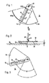
- FIGS. 1 to 3 is denoted by the reference numeral 10 to a predetermined length L * tailored, ie cut to length sintered metal blank, which consists for example of a hard metal powder with kneaded binding or adhesive.
- This sintered metal blank is produced for example by extrusion, in such a way that it has a straight and continuous, shown in the figures with dotted line inner recess 12 which extends parallel to the center axis 14 of the circular cylindrical blank 10.
- the production of the sintered metal blank is preferably carried out in the extrusion process with the aid of an extrusion die with a suitable core.
- the blank 10 has a relatively soft consistency, so that the handling, such. As the transport, must be done very carefully to prevent irreversible deformation. Therefore, the blank is preferably performed immediately after exiting the extrusion die on an air cushion and directed to the pad 16 shown in the figures, which in the FIGS. 1 and 3 coincides with the presentation plane.
- the blank is due to the consistency of the extruded mass on its outside sticky, so that a good adhesion with the support surface 16 results.
- a circular segment disc 18 with a bottom-side friction surface 20 is arranged.
- the circular segment disc 18 is rotatable about an axis of rotation 22 which is perpendicular to the surface of the support 16 and on the friction surface.
- the vertical distance AV between the surfaces 16 and 20 is preferably adjustable, which is indicated by the double arrow V in FIG. 2 is indicated. This vertical distance AV corresponds to the diameter D of the blank 10.
- the blank 10 is placed on the support 16 so that its longitudinal axis 14, the axis of rotation 22 of the circular segment disc 18 cuts. Subsequently, the circular segment disc is lowered controlled so that it touches the blank 10 along a line which is offset diametrically to the bottom-side contact line of the blank 10 with the support 16. This alignment is in the Figures 1 and 2 shown.
- the circular segment disc 18 is pivoted at an angular velocity ⁇ . Due to the frictional contact between the surface 20 of the circular segment disc 18 and the blank 10 of the blank is taken by rolling on the surface of the support 16 at a speed that changes linearly and steadily along the axis of the blank 10.
- the rolling speed at the inner end of the blank 10 is VWI and the rolling speed at the outer end of the blank 10 is designated VWA.
- the circular segment disc 18 is held in contact with the rod-shaped blank 10 with as little contact force as possible, specifically during the entire twisting operation, ie during the entire pivoting about the pivoting angle ⁇ (see FIG. Fig. 3 ).
- a change in the axis of rotation in contrast to the reference to the FIGS. 1 to 3 described prior art during the rolling process, a change in the axis of rotation.
- This change in the axis of rotation takes place in particular such that all longitudinal sections of the blank during the rolling process each cover the same rolling distance.
- the rolling process takes place in two successive steps, wherein in the first step, a rolling movement about a first axis of rotation and in the second step, a rolling movement about a second axis of rotation takes place.
- a method according to the invention serves as well as that of EP-B1-1 230 046 known method for producing a circular cylindrical body consisting of plastic mass, in particular a sintered metal blank, which has at least one helical inner recess running in the interior of the body.
- the body is as well as in the EP-B1-1 230 046 known method initially prepared with a straight course of the inner recess, for example extruded.
- the extruded body is cut to a desired length. Subsequently, it is subjected to a rolling process with support over its entire length on a support with a friction surface arrangement, so that a twisting of the body takes place.
- the rolling process takes place in two successive steps, wherein in the first step, a rolling movement about a first axis of rotation and in the second step, a rolling movement about a second axis of rotation, wherein the second axis of rotation is different from the first axis of rotation.
- the rolling process takes place in such a way that each longitudinal section of the circular-cylindrical body travels the same path during the rolling process. The Rolling direction is maintained in the successive steps.
- the positioning of the axes of rotation is such that during the first step, the axis of rotation intersects the center line of the circular cylindrical body in the region of an axial end surface of the circular cylindrical body and during the second step, the axis of rotation of the center line of the circular cylindrical body in the area the other axial end surface of the circular cylindrical body intersects.
- the positioning of the axes of rotation is such that during the first step, the axis of rotation intersects the extended centerline of the circular cylindrical body at a predetermined distance from an axial end surface of the circular cylindrical body and during the second step the axis of rotation extends Center line of the circular cylindrical body at the same predetermined distance from the other axial end surface of the circular cylindrical body intersects.
- Another embodiment of the invention is to change the axis of rotation about which the rolling movement occurs during the rolling movement several times or continuously.
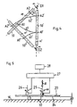
- FIG. 4 shows a sketch to illustrate the change of the axis of rotation during the rolling process.
- the circular cylindrical body 10 is in the position in which it is represented by the reference numeral 10.
- a twisting of the body using the Rotation axis D1 which runs perpendicular to the plane of the drawing.
- the body is moved through an angle in the FIG. 4 in the vicinity of the rotation axis D1 is denoted by "a".
- the rotation axis D1 intersects the center line M of the circular cylindrical body at a predetermined distance from an axial end portion of the circular cylindrical body.
- the velocity changes linearly and steadily over the length of the body.
- the body is in a position offset by the angle ⁇ . He is there with the reference numeral 10 'provided.
- a second step the body is twisted using a rotation axis D2. This also runs perpendicular to the drawing plane.
- the rotation axis D2 intersects the center line M 'of the circular cylindrical body 10' at a predetermined distance from the other axial end surface of the circular cylindrical body.
- the body is moved through an angle, which in the FIG. 4 in the vicinity of the rotation axis D2 is also denoted by " ⁇ ". Even with this twisting, the speed changes linearly and steadily over the length of the body.
- the body is in a position offset by the angle ⁇ . He is there with the reference numeral 10 "provided.
- the entire twisting process is tuned to the effect that the different longitudinal sections of the circular cylindrical body cover the same distance or twisting distance during the entire twisting process. This is in the FIG. 4 illustrated by the longitudinal sections A1 and A2 of the circular cylindrical body.
- the longitudinal section A1 of the circular cylindrical body is in the first step to those in the FIG. 4 moved with s1 path. After completion of the first step this longitudinal section is located in the body 10 'and is designated there by A1'.
- FIG. 5 shows a sketch to illustrate a device for carrying out the method according to the invention.
- This device has a flat support surface 16.
- a Wälzin 23 is arranged in the vertical distance AV to this .
- This has a pad surface side friction surface 24.
- the Wälzin 23 is rotatable about an axis of rotation 25 which is perpendicular to the surface of the support surface 16. This rotation takes place at an angular velocity ⁇ .
- the vertical distance AV between the support surface 16 and the Wälzsay 23 is adjustable, as indicated by the double arrow V.
- the rolling movement takes place using the axis of rotation 25.
- the rolling movement takes place using a second axis of rotation 26, which is also perpendicular to the surface of the support surface 16.
- This rotation also takes place at the angular velocity ⁇ .
- the rolling direction in the second step coincides with the rolling direction in the first step.
Landscapes
- Engineering & Computer Science (AREA)
- Mechanical Engineering (AREA)
- Manufacturing & Machinery (AREA)
- Structural Engineering (AREA)
- Chemical & Material Sciences (AREA)
- Ceramic Engineering (AREA)
- Powder Metallurgy (AREA)
- Rolling Contact Bearings (AREA)
- Forging (AREA)
- Physical Vapour Deposition (AREA)
- Shaping By String And By Release Of Stress In Plastics And The Like (AREA)
- Shafts, Cranks, Connecting Bars, And Related Bearings (AREA)
Applications Claiming Priority (2)
| Application Number | Priority Date | Filing Date | Title |
|---|---|---|---|
| DE102008033413A DE102008033413A1 (de) | 2008-07-16 | 2008-07-16 | Verfahren und Vorrichtung zur Herstellung eines aus plastischer Masse bestehenden kreiszylindrischen Körpers mit innenliegenden wendelförmigen Ausnehmungen |
| PCT/EP2009/057583 WO2010006873A1 (de) | 2008-07-16 | 2009-06-18 | Verfahren und vorrichtung zur herstellung eines aus plastischer masse bestehenden kreiszylindrischen körpers mit innenliegenden wendelförmigen ausnehmungen |
Publications (2)
| Publication Number | Publication Date |
|---|---|
| EP2313218A1 EP2313218A1 (de) | 2011-04-27 |
| EP2313218B1 true EP2313218B1 (de) | 2011-10-19 |
Family
ID=41066151
Family Applications (1)
| Application Number | Title | Priority Date | Filing Date |
|---|---|---|---|
| EP09779827A Active EP2313218B1 (de) | 2008-07-16 | 2009-06-18 | Verfahren und vorrichtung zur herstellung eines aus plastischer masse bestehenden kreiszylindrischen körpers mit innenliegenden wendelförmigen ausnehmungen |
Country Status (9)
| Country | Link |
|---|---|
| US (2) | US8850861B2 (enExample) |
| EP (1) | EP2313218B1 (enExample) |
| JP (1) | JP5453414B2 (enExample) |
| KR (1) | KR101264755B1 (enExample) |
| CN (1) | CN102099134B (enExample) |
| AT (1) | ATE529206T1 (enExample) |
| DE (1) | DE102008033413A1 (enExample) |
| ES (1) | ES2373634T3 (enExample) |
| WO (1) | WO2010006873A1 (enExample) |
Cited By (1)
| Publication number | Priority date | Publication date | Assignee | Title |
|---|---|---|---|---|
| WO2019057351A1 (de) | 2017-09-21 | 2019-03-28 | Arno Friedrichs | Verfahren und vorrichtung zur herstellung eines aus plastischer masse bestehenden kreiszylindrischen körpers |
Families Citing this family (2)
| Publication number | Priority date | Publication date | Assignee | Title |
|---|---|---|---|---|
| DE102014115760A1 (de) | 2014-10-30 | 2016-05-04 | Arno Friedrichs | Schneidwerkzeug mit innenliegenden, spiralförmig verlaufenden Kühlmittelkanälen mit sich veränderndem Steigungswinkel |
| CN109249026A (zh) * | 2018-11-12 | 2019-01-22 | 深圳艾利佳材料科技有限公司 | 一种用粉末挤出轧制的成型工艺 |
Family Cites Families (10)
| Publication number | Priority date | Publication date | Assignee | Title |
|---|---|---|---|---|
| EP0173675A1 (de) | 1984-08-28 | 1986-03-05 | Vereinigte Edelstahlwerke Aktiengesellschaft (Vew) | Verfahren und Vorrichtung zur Herstellung von, insbesondere metallischen, Werkstücken, vorzugsweise aus Stahl |
| JPH0663003B2 (ja) | 1989-09-08 | 1994-08-17 | 東芝タンガロイ株式会社 | 押出し成形機 |
| DE4120165C2 (de) | 1990-07-05 | 1995-01-26 | Friedrichs Konrad Kg | Strangpreßwerkzeug zur Herstellung eines Hartmetall- oder Keramikstabes |
| JPH04198405A (ja) | 1990-11-28 | 1992-07-17 | Kobe Steel Ltd | 穴付硬質長尺素材の製造方法 |
| JPH04198404A (ja) | 1990-11-28 | 1992-07-17 | Kobe Steel Ltd | 穴付硬質長尺素材の製造方法 |
| JPH04210407A (ja) | 1990-11-30 | 1992-07-31 | Kobe Steel Ltd | 油穴付ドリル,エンドミルの製造方法 |
| US5152061A (en) | 1992-02-19 | 1992-10-06 | Tesma International Inc. | Cold-forming of toothed wheels from sheet steel |
| DE50003038D1 (de) | 1999-09-09 | 2003-08-28 | Arno Friedrichs | Verfahren und vorrichtung zur herstellung eines sintermetall-rohlings mit innenliegenden, wendelförmigen ausnehmungen |
| DE10356111B4 (de) * | 2003-11-27 | 2006-10-12 | Zf Friedrichshafen Ag | Kaltumformverfahren zur Herstellung von einteiligen Kugelzapfen |
| CN1974054A (zh) * | 2006-12-08 | 2007-06-06 | 青特集团有限公司 | 多阶细长轴的制造工艺 |
-
2008
- 2008-07-16 DE DE102008033413A patent/DE102008033413A1/de not_active Withdrawn
-
2009
- 2009-06-18 EP EP09779827A patent/EP2313218B1/de active Active
- 2009-06-18 ES ES09779827T patent/ES2373634T3/es active Active
- 2009-06-18 CN CN2009801273681A patent/CN102099134B/zh active Active
- 2009-06-18 KR KR1020117001088A patent/KR101264755B1/ko not_active Expired - Fee Related
- 2009-06-18 AT AT09779827T patent/ATE529206T1/de active
- 2009-06-18 WO PCT/EP2009/057583 patent/WO2010006873A1/de not_active Ceased
- 2009-06-18 US US12/737,444 patent/US8850861B2/en active Active
- 2009-06-18 JP JP2011517837A patent/JP5453414B2/ja active Active
-
2014
- 2014-08-28 US US14/471,318 patent/US9044797B2/en active Active
Cited By (1)
| Publication number | Priority date | Publication date | Assignee | Title |
|---|---|---|---|---|
| WO2019057351A1 (de) | 2017-09-21 | 2019-03-28 | Arno Friedrichs | Verfahren und vorrichtung zur herstellung eines aus plastischer masse bestehenden kreiszylindrischen körpers |
Also Published As
| Publication number | Publication date |
|---|---|
| JP5453414B2 (ja) | 2014-03-26 |
| US8850861B2 (en) | 2014-10-07 |
| US9044797B2 (en) | 2015-06-02 |
| KR20110031950A (ko) | 2011-03-29 |
| EP2313218A1 (de) | 2011-04-27 |
| ES2373634T3 (es) | 2012-02-07 |
| ATE529206T1 (de) | 2011-11-15 |
| US20110113846A1 (en) | 2011-05-19 |
| US20150027188A1 (en) | 2015-01-29 |
| KR101264755B1 (ko) | 2013-05-15 |
| DE102008033413A1 (de) | 2010-01-21 |
| WO2010006873A1 (de) | 2010-01-21 |
| CN102099134B (zh) | 2013-05-22 |
| JP2011527943A (ja) | 2011-11-10 |
| CN102099134A (zh) | 2011-06-15 |
Similar Documents
| Publication | Publication Date | Title |
|---|---|---|
| EP0465946B1 (de) | Hartmetall- oder Keramikstab, Verfahren zu seiner Herstellung und Strangpresswerkzeug zur Durchführung des Verfahrens | |
| EP1017527B1 (de) | Verfahren und vorrichtung zur kontinuierlichen extrusion von mit einem wendelförmigen innenkanal ausgestatteten stäben aus plastischem rohmaterial | |
| DE4120166A1 (de) | Strangpresswerkzeug zur herstellung eines hartmetall- oder keramikstabes mit gedrallten innenbohrungen | |
| DE102014108219A1 (de) | Rotationswerkzeug sowie Verfahren zur Herstellung eines Rotationswerkzeugs | |
| EP2127777A1 (de) | Vorrichtung und Verfahren zum Herstellen oder Bearbeiten von Werkstücken aus einer Vorform, insbesondere zum Anformen von Innenprofilen oder Innenverzahnungen | |
| EP1340573A1 (de) | Verfahren zur Herstellung eines Werkzeugs, insbesondere eines Bohrers oder Fräsers | |
| WO2004056513A2 (de) | Sinterrohlingen mit gewendelten kühlkanälen | |
| EP1230046B1 (de) | Verfahren und vorrichtung zur herstellung eines sintermetall-rohlings mit innenliegenden, wendelförmigen ausnehmungen | |
| EP0458774B2 (de) | Hartmetall- oder Keramikrohling sowie Verfahren und Werkzeug zur Herstellung derselben | |
| EP2313218B1 (de) | Verfahren und vorrichtung zur herstellung eines aus plastischer masse bestehenden kreiszylindrischen körpers mit innenliegenden wendelförmigen ausnehmungen | |
| DE102018202941B4 (de) | Verfahren zur Herstellung eines Rohlings aus Extrusionsmasse sowie Extruder | |
| DE2808081A1 (de) | Verfahren und vorrichtung zum herstellen wendelfoermiger rotorrohlinge fuer exzenterschneckenpumpen | |
| EP3684585B1 (de) | Verfahren und vorrichtung zur herstellung eines aus plastischer masse bestehenden kreiszylindrischen körpers | |
| DE19942966C2 (de) | Verfahren und Vorrichtung zur Herstellung eines Sintermetall-Rohlings mit innenliegenden, wendelförmigen Ausnehmungen | |
| DE20307412U1 (de) | Werkzeug zur Extrusion eines rohrförmigen Schmelzestranges | |
| DE10229325B4 (de) | Strangpresswerkzeug zur Herstellung eines aus plastischer Masse bestehenden zylindrischen Körpers | |
| DE102005019921A1 (de) | Werkzeug und Verfahren zur Erzeugung oder Nachbearbeitung eines Gewindes | |
| DE4021383C2 (de) | Verfahren zur Herstellung eines Hartmetall- oder Keramikstabes und Strangpreßwerkzeug zur Durchführung des Verfahrens | |
| EP0634959B1 (de) | Verfahren und vorrichtung zur kontinuierlichen herstellung von zylindrischen stäben mit zumindest einem innenliegenden, wendelförmigen kanal, und nach diesem verfahren hergestellter sinterrohling | |
| DE4242336A1 (de) | Verfahren und Vorrichtung zur kontinuierlichen Herstellung von zylindrischen Stäben mit zumindest einem innenliegenden, wendelförmigen Kanal, und nach diesem Verfahren hergestellter Sinterrohling | |
| DE4211827C2 (de) | Verfahren und Strangpreßwerkzeug zur kontinuierlichen Herstellung von zylindrischen Stäben mit zumindest einem innenliegenden, wendelförmigen Kanal, und nach diesem Verfahren hergestellter Stab | |
| DE29624253U1 (de) | Vorrichtung zur kontinuierlichen Extrusion von mit einem wendelförmigen Innenkanal ausgestatteten Stäben aus plastischem Rohmaterial | |
| WO2004002642A1 (de) | Strangpresswekzeug zur herstellung eines aus plastischer masse bestehenden zylindrischen körpers | |
| EP1285706A1 (de) | Verfahren zur spanlosen Fertigung eines nicht-rotationssymmetrischen Werkstücks sowie Drückwalzmaschine | |
| DE10208633A1 (de) | Werkzeug, insbesondere Bohrer oder Fräser, und Verfahren zu dessen Herstellung |
Legal Events
| Date | Code | Title | Description |
|---|---|---|---|
| PUAI | Public reference made under article 153(3) epc to a published international application that has entered the european phase |
Free format text: ORIGINAL CODE: 0009012 |
|
| 17P | Request for examination filed |
Effective date: 20110216 |
|
| AK | Designated contracting states |
Kind code of ref document: A1 Designated state(s): AT BE BG CH CY CZ DE DK EE ES FI FR GB GR HR HU IE IS IT LI LT LU LV MC MK MT NL NO PL PT RO SE SI SK TR |
|
| AX | Request for extension of the european patent |
Extension state: AL BA RS |
|
| GRAP | Despatch of communication of intention to grant a patent |
Free format text: ORIGINAL CODE: EPIDOSNIGR1 |
|
| DAX | Request for extension of the european patent (deleted) | ||
| GRAS | Grant fee paid |
Free format text: ORIGINAL CODE: EPIDOSNIGR3 |
|
| GRAA | (expected) grant |
Free format text: ORIGINAL CODE: 0009210 |
|
| RAP1 | Party data changed (applicant data changed or rights of an application transferred) |
Owner name: FRIEDRICHS, ARNO |
|
| RIN1 | Information on inventor provided before grant (corrected) |
Inventor name: FRIEDRICHS, ARNO |
|
| AK | Designated contracting states |
Kind code of ref document: B1 Designated state(s): AT BE BG CH CY CZ DE DK EE ES FI FR GB GR HR HU IE IS IT LI LT LU LV MC MK MT NL NO PL PT RO SE SI SK TR |
|
| REG | Reference to a national code |
Ref country code: GB Ref legal event code: FG4D Free format text: NOT ENGLISH |
|
| REG | Reference to a national code |
Ref country code: CH Ref legal event code: EP |
|
| REG | Reference to a national code |
Ref country code: IE Ref legal event code: FG4D |
|
| REG | Reference to a national code |
Ref country code: CH Ref legal event code: NV Representative=s name: KELLER & PARTNER PATENTANWAELTE AG |
|
| REG | Reference to a national code |
Ref country code: DE Ref legal event code: R096 Ref document number: 502009001675 Country of ref document: DE Effective date: 20111229 |
|
| REG | Reference to a national code |
Ref country code: SE Ref legal event code: TRGR Ref country code: ES Ref legal event code: FG2A Ref document number: 2373634 Country of ref document: ES Kind code of ref document: T3 Effective date: 20120207 |
|
| REG | Reference to a national code |
Ref country code: NL Ref legal event code: VDEP Effective date: 20111019 |
|
| LTIE | Lt: invalidation of european patent or patent extension |
Effective date: 20111019 |
|
| PG25 | Lapsed in a contracting state [announced via postgrant information from national office to epo] |
Ref country code: IS Free format text: LAPSE BECAUSE OF FAILURE TO SUBMIT A TRANSLATION OF THE DESCRIPTION OR TO PAY THE FEE WITHIN THE PRESCRIBED TIME-LIMIT Effective date: 20120219 Ref country code: NO Free format text: LAPSE BECAUSE OF FAILURE TO SUBMIT A TRANSLATION OF THE DESCRIPTION OR TO PAY THE FEE WITHIN THE PRESCRIBED TIME-LIMIT Effective date: 20120119 Ref country code: LT Free format text: LAPSE BECAUSE OF FAILURE TO SUBMIT A TRANSLATION OF THE DESCRIPTION OR TO PAY THE FEE WITHIN THE PRESCRIBED TIME-LIMIT Effective date: 20111019 |
|
| PG25 | Lapsed in a contracting state [announced via postgrant information from national office to epo] |
Ref country code: PT Free format text: LAPSE BECAUSE OF FAILURE TO SUBMIT A TRANSLATION OF THE DESCRIPTION OR TO PAY THE FEE WITHIN THE PRESCRIBED TIME-LIMIT Effective date: 20120220 Ref country code: LV Free format text: LAPSE BECAUSE OF FAILURE TO SUBMIT A TRANSLATION OF THE DESCRIPTION OR TO PAY THE FEE WITHIN THE PRESCRIBED TIME-LIMIT Effective date: 20111019 Ref country code: GR Free format text: LAPSE BECAUSE OF FAILURE TO SUBMIT A TRANSLATION OF THE DESCRIPTION OR TO PAY THE FEE WITHIN THE PRESCRIBED TIME-LIMIT Effective date: 20120120 Ref country code: HR Free format text: LAPSE BECAUSE OF FAILURE TO SUBMIT A TRANSLATION OF THE DESCRIPTION OR TO PAY THE FEE WITHIN THE PRESCRIBED TIME-LIMIT Effective date: 20111019 Ref country code: SI Free format text: LAPSE BECAUSE OF FAILURE TO SUBMIT A TRANSLATION OF THE DESCRIPTION OR TO PAY THE FEE WITHIN THE PRESCRIBED TIME-LIMIT Effective date: 20111019 Ref country code: NL Free format text: LAPSE BECAUSE OF FAILURE TO SUBMIT A TRANSLATION OF THE DESCRIPTION OR TO PAY THE FEE WITHIN THE PRESCRIBED TIME-LIMIT Effective date: 20111019 |
|
| PG25 | Lapsed in a contracting state [announced via postgrant information from national office to epo] |
Ref country code: CY Free format text: LAPSE BECAUSE OF FAILURE TO SUBMIT A TRANSLATION OF THE DESCRIPTION OR TO PAY THE FEE WITHIN THE PRESCRIBED TIME-LIMIT Effective date: 20111019 |
|
| PG25 | Lapsed in a contracting state [announced via postgrant information from national office to epo] |
Ref country code: SK Free format text: LAPSE BECAUSE OF FAILURE TO SUBMIT A TRANSLATION OF THE DESCRIPTION OR TO PAY THE FEE WITHIN THE PRESCRIBED TIME-LIMIT Effective date: 20111019 Ref country code: BG Free format text: LAPSE BECAUSE OF FAILURE TO SUBMIT A TRANSLATION OF THE DESCRIPTION OR TO PAY THE FEE WITHIN THE PRESCRIBED TIME-LIMIT Effective date: 20120119 Ref country code: DK Free format text: LAPSE BECAUSE OF FAILURE TO SUBMIT A TRANSLATION OF THE DESCRIPTION OR TO PAY THE FEE WITHIN THE PRESCRIBED TIME-LIMIT Effective date: 20111019 Ref country code: CZ Free format text: LAPSE BECAUSE OF FAILURE TO SUBMIT A TRANSLATION OF THE DESCRIPTION OR TO PAY THE FEE WITHIN THE PRESCRIBED TIME-LIMIT Effective date: 20111019 Ref country code: EE Free format text: LAPSE BECAUSE OF FAILURE TO SUBMIT A TRANSLATION OF THE DESCRIPTION OR TO PAY THE FEE WITHIN THE PRESCRIBED TIME-LIMIT Effective date: 20111019 |
|
| PLBE | No opposition filed within time limit |
Free format text: ORIGINAL CODE: 0009261 |
|
| STAA | Information on the status of an ep patent application or granted ep patent |
Free format text: STATUS: NO OPPOSITION FILED WITHIN TIME LIMIT |
|
| PG25 | Lapsed in a contracting state [announced via postgrant information from national office to epo] |
Ref country code: RO Free format text: LAPSE BECAUSE OF FAILURE TO SUBMIT A TRANSLATION OF THE DESCRIPTION OR TO PAY THE FEE WITHIN THE PRESCRIBED TIME-LIMIT Effective date: 20111019 Ref country code: PL Free format text: LAPSE BECAUSE OF FAILURE TO SUBMIT A TRANSLATION OF THE DESCRIPTION OR TO PAY THE FEE WITHIN THE PRESCRIBED TIME-LIMIT Effective date: 20111019 |
|
| 26N | No opposition filed |
Effective date: 20120720 |
|
| REG | Reference to a national code |
Ref country code: DE Ref legal event code: R097 Ref document number: 502009001675 Country of ref document: DE Effective date: 20120720 |
|
| BERE | Be: lapsed |
Owner name: FRIEDRICHS, ARNO Effective date: 20120630 |
|
| PG25 | Lapsed in a contracting state [announced via postgrant information from national office to epo] |
Ref country code: MC Free format text: LAPSE BECAUSE OF NON-PAYMENT OF DUE FEES Effective date: 20120630 |
|
| PG25 | Lapsed in a contracting state [announced via postgrant information from national office to epo] |
Ref country code: MK Free format text: LAPSE BECAUSE OF FAILURE TO SUBMIT A TRANSLATION OF THE DESCRIPTION OR TO PAY THE FEE WITHIN THE PRESCRIBED TIME-LIMIT Effective date: 20111019 |
|
| PG25 | Lapsed in a contracting state [announced via postgrant information from national office to epo] |
Ref country code: BE Free format text: LAPSE BECAUSE OF NON-PAYMENT OF DUE FEES Effective date: 20120630 |
|
| PG25 | Lapsed in a contracting state [announced via postgrant information from national office to epo] |
Ref country code: FI Free format text: LAPSE BECAUSE OF FAILURE TO SUBMIT A TRANSLATION OF THE DESCRIPTION OR TO PAY THE FEE WITHIN THE PRESCRIBED TIME-LIMIT Effective date: 20111019 |
|
| PG25 | Lapsed in a contracting state [announced via postgrant information from national office to epo] |
Ref country code: MT Free format text: LAPSE BECAUSE OF FAILURE TO SUBMIT A TRANSLATION OF THE DESCRIPTION OR TO PAY THE FEE WITHIN THE PRESCRIBED TIME-LIMIT Effective date: 20111019 |
|
| PG25 | Lapsed in a contracting state [announced via postgrant information from national office to epo] |
Ref country code: TR Free format text: LAPSE BECAUSE OF FAILURE TO SUBMIT A TRANSLATION OF THE DESCRIPTION OR TO PAY THE FEE WITHIN THE PRESCRIBED TIME-LIMIT Effective date: 20111019 |
|
| PG25 | Lapsed in a contracting state [announced via postgrant information from national office to epo] |
Ref country code: HU Free format text: LAPSE BECAUSE OF FAILURE TO SUBMIT A TRANSLATION OF THE DESCRIPTION OR TO PAY THE FEE WITHIN THE PRESCRIBED TIME-LIMIT Effective date: 20090618 |
|
| REG | Reference to a national code |
Ref country code: DE Ref legal event code: R082 Ref document number: 502009001675 Country of ref document: DE Representative=s name: ZIMMERMANN & PARTNER, DE Ref country code: DE Ref legal event code: R082 Ref document number: 502009001675 Country of ref document: DE Representative=s name: ZIMMERMANN & PARTNER PATENTANWAELTE MBB, DE |
|
| REG | Reference to a national code |
Ref country code: CH Ref legal event code: PCAR Free format text: NEW ADDRESS: EIGERSTRASSE 2 POSTFACH, 3000 BERN 14 (CH) |
|
| REG | Reference to a national code |
Ref country code: FR Ref legal event code: PLFP Year of fee payment: 7 |
|
| REG | Reference to a national code |
Ref country code: FR Ref legal event code: PLFP Year of fee payment: 8 |
|
| REG | Reference to a national code |
Ref country code: FR Ref legal event code: PLFP Year of fee payment: 9 |
|
| REG | Reference to a national code |
Ref country code: FR Ref legal event code: PLFP Year of fee payment: 10 |
|
| REG | Reference to a national code |
Ref country code: DE Ref legal event code: R082 Ref document number: 502009001675 Country of ref document: DE Representative=s name: ZIMMERMANN & PARTNER PATENTANWAELTE MBB, DE Ref country code: DE Ref legal event code: R081 Ref document number: 502009001675 Country of ref document: DE Owner name: ARNO FRIEDRICHS HARTMETALL GMBH & CO. KG, DE Free format text: FORMER OWNER: FRIEDRICHS, ARNO, 95326 KULMBACH, DE |
|
| REG | Reference to a national code |
Ref country code: CH Ref legal event code: PUE Owner name: ARNO FRIEDRICHS HARTMETALL GMBH AND CO. KG, DE Free format text: FORMER OWNER: FRIEDRICHS, ARNO, DE |
|
| REG | Reference to a national code |
Ref country code: ES Ref legal event code: PC2A Owner name: ARNO FRIEDRICHS HARTMETALL GMBH & CO.KG Effective date: 20191212 |
|
| REG | Reference to a national code |
Ref country code: LU Ref legal event code: PD Owner name: ARNO FRIEDRICHS HARTMETALL GMBH & CO. KG; DE Free format text: FORMER OWNER: FRIEDRICHS ARNO Effective date: 20191203 |
|
| REG | Reference to a national code |
Ref country code: GB Ref legal event code: 732E Free format text: REGISTERED BETWEEN 20200102 AND 20200108 |
|
| REG | Reference to a national code |
Ref country code: AT Ref legal event code: PC Ref document number: 529206 Country of ref document: AT Kind code of ref document: T Owner name: ARNO FRIEDRICHS HARTMETALL GMBH & CO. KG, DE Effective date: 20200312 |
|
| REG | Reference to a national code |
Ref country code: CH Ref legal event code: PFA Owner name: ARNO FRIEDRICHS HARTMETALL GMBH AND CO. KG, DE Free format text: FORMER OWNER: ARNO FRIEDRICHS HARTMETALL GMBH AND CO. KG, DE |
|
| P01 | Opt-out of the competence of the unified patent court (upc) registered |
Effective date: 20230703 |
|
| PGFP | Annual fee paid to national office [announced via postgrant information from national office to epo] |
Ref country code: DE Payment date: 20250627 Year of fee payment: 17 |
|
| PGFP | Annual fee paid to national office [announced via postgrant information from national office to epo] |
Ref country code: GB Payment date: 20250627 Year of fee payment: 17 |
|
| PGFP | Annual fee paid to national office [announced via postgrant information from national office to epo] |
Ref country code: LU Payment date: 20250627 Year of fee payment: 17 |
|
| PGFP | Annual fee paid to national office [announced via postgrant information from national office to epo] |
Ref country code: FR Payment date: 20250625 Year of fee payment: 17 |
|
| PGFP | Annual fee paid to national office [announced via postgrant information from national office to epo] |
Ref country code: AT Payment date: 20250603 Year of fee payment: 17 |
|
| PGFP | Annual fee paid to national office [announced via postgrant information from national office to epo] |
Ref country code: IE Payment date: 20250627 Year of fee payment: 17 |
|
| PGFP | Annual fee paid to national office [announced via postgrant information from national office to epo] |
Ref country code: SE Payment date: 20250627 Year of fee payment: 17 |
|
| PGFP | Annual fee paid to national office [announced via postgrant information from national office to epo] |
Ref country code: ES Payment date: 20250701 Year of fee payment: 17 |
|
| PGFP | Annual fee paid to national office [announced via postgrant information from national office to epo] |
Ref country code: IT Payment date: 20250619 Year of fee payment: 17 |
|
| PGFP | Annual fee paid to national office [announced via postgrant information from national office to epo] |
Ref country code: CH Payment date: 20250701 Year of fee payment: 17 |