EP2313218B1 - Method and apparatus for producing a circular cylindrical body comprising a workable mass and having internal helical recesses - Google Patents
Method and apparatus for producing a circular cylindrical body comprising a workable mass and having internal helical recesses Download PDFInfo
- Publication number
- EP2313218B1 EP2313218B1 EP09779827A EP09779827A EP2313218B1 EP 2313218 B1 EP2313218 B1 EP 2313218B1 EP 09779827 A EP09779827 A EP 09779827A EP 09779827 A EP09779827 A EP 09779827A EP 2313218 B1 EP2313218 B1 EP 2313218B1
- Authority
- EP
- European Patent Office
- Prior art keywords
- rotation
- friction surface
- axis
- cylindrical body
- surface arrangement
- Prior art date
- Legal status (The legal status is an assumption and is not a legal conclusion. Google has not performed a legal analysis and makes no representation as to the accuracy of the status listed.)
- Active
Links
- 238000000034 method Methods 0.000 title claims abstract description 39
- 238000005096 rolling process Methods 0.000 claims abstract description 53
- 230000033001 locomotion Effects 0.000 claims abstract description 21
- 229920003023 plastic Polymers 0.000 claims description 9
- 239000004033 plastic Substances 0.000 claims description 9
- 239000000463 material Substances 0.000 claims description 2
- 230000002035 prolonged effect Effects 0.000 claims 2
- 238000001125 extrusion Methods 0.000 abstract description 14
- 239000002184 metal Substances 0.000 description 12
- 238000004519 manufacturing process Methods 0.000 description 8
- 238000005553 drilling Methods 0.000 description 5
- 238000005520 cutting process Methods 0.000 description 3
- 239000000843 powder Substances 0.000 description 3
- 238000003825 pressing Methods 0.000 description 3
- 239000000919 ceramic Substances 0.000 description 2
- 238000001816 cooling Methods 0.000 description 2
- 230000001419 dependent effect Effects 0.000 description 2
- 238000011161 development Methods 0.000 description 2
- 230000018109 developmental process Effects 0.000 description 2
- 238000000227 grinding Methods 0.000 description 2
- 238000005245 sintering Methods 0.000 description 2
- 239000000853 adhesive Substances 0.000 description 1
- 230000001070 adhesive effect Effects 0.000 description 1
- 238000013459 approach Methods 0.000 description 1
- 239000011230 binding agent Substances 0.000 description 1
- 230000015572 biosynthetic process Effects 0.000 description 1
- 229910010293 ceramic material Inorganic materials 0.000 description 1
- 238000007796 conventional method Methods 0.000 description 1
- 239000002826 coolant Substances 0.000 description 1
- 238000009826 distribution Methods 0.000 description 1
- 230000000694 effects Effects 0.000 description 1
- 230000002349 favourable effect Effects 0.000 description 1
- 230000002427 irreversible effect Effects 0.000 description 1
- 239000000314 lubricant Substances 0.000 description 1
- 238000003754 machining Methods 0.000 description 1
- 238000012423 maintenance Methods 0.000 description 1
- 230000002441 reversible effect Effects 0.000 description 1
- 239000007787 solid Substances 0.000 description 1
Images
Classifications
-
- B—PERFORMING OPERATIONS; TRANSPORTING
- B21—MECHANICAL METAL-WORKING WITHOUT ESSENTIALLY REMOVING MATERIAL; PUNCHING METAL
- B21B—ROLLING OF METAL
- B21B1/00—Metal-rolling methods or mills for making semi-finished products of solid or profiled cross-section; Sequence of operations in milling trains; Layout of rolling-mill plant, e.g. grouping of stands; Succession of passes or of sectional pass alternations
- B21B1/16—Metal-rolling methods or mills for making semi-finished products of solid or profiled cross-section; Sequence of operations in milling trains; Layout of rolling-mill plant, e.g. grouping of stands; Succession of passes or of sectional pass alternations for rolling wire rods, bars, merchant bars, rounds wire or material of like small cross-section
-
- B—PERFORMING OPERATIONS; TRANSPORTING
- B21—MECHANICAL METAL-WORKING WITHOUT ESSENTIALLY REMOVING MATERIAL; PUNCHING METAL
- B21K—MAKING FORGED OR PRESSED METAL PRODUCTS, e.g. HORSE-SHOES, RIVETS, BOLTS OR WHEELS
- B21K5/00—Making tools or tool parts, e.g. pliers
- B21K5/02—Making tools or tool parts, e.g. pliers drilling-tools or other for making or working on holes
- B21K5/04—Making tools or tool parts, e.g. pliers drilling-tools or other for making or working on holes twisting-tools, e.g. drills, reamers
-
- B—PERFORMING OPERATIONS; TRANSPORTING
- B21—MECHANICAL METAL-WORKING WITHOUT ESSENTIALLY REMOVING MATERIAL; PUNCHING METAL
- B21H—MAKING PARTICULAR METAL OBJECTS BY ROLLING, e.g. SCREWS, WHEELS, RINGS, BARRELS, BALLS
- B21H1/00—Making articles shaped as bodies of revolution
- B21H1/18—Making articles shaped as bodies of revolution cylinders, e.g. rolled transversely cross-rolling
-
- B—PERFORMING OPERATIONS; TRANSPORTING
- B21—MECHANICAL METAL-WORKING WITHOUT ESSENTIALLY REMOVING MATERIAL; PUNCHING METAL
- B21H—MAKING PARTICULAR METAL OBJECTS BY ROLLING, e.g. SCREWS, WHEELS, RINGS, BARRELS, BALLS
- B21H3/00—Making helical bodies or bodies having parts of helical shape
- B21H3/10—Making helical bodies or bodies having parts of helical shape twist-drills; screw-taps
-
- B—PERFORMING OPERATIONS; TRANSPORTING
- B22—CASTING; POWDER METALLURGY
- B22F—WORKING METALLIC POWDER; MANUFACTURE OF ARTICLES FROM METALLIC POWDER; MAKING METALLIC POWDER; APPARATUS OR DEVICES SPECIALLY ADAPTED FOR METALLIC POWDER
- B22F3/00—Manufacture of workpieces or articles from metallic powder characterised by the manner of compacting or sintering; Apparatus specially adapted therefor ; Presses and furnaces
- B22F3/18—Manufacture of workpieces or articles from metallic powder characterised by the manner of compacting or sintering; Apparatus specially adapted therefor ; Presses and furnaces by using pressure rollers
-
- B—PERFORMING OPERATIONS; TRANSPORTING
- B22—CASTING; POWDER METALLURGY
- B22F—WORKING METALLIC POWDER; MANUFACTURE OF ARTICLES FROM METALLIC POWDER; MAKING METALLIC POWDER; APPARATUS OR DEVICES SPECIALLY ADAPTED FOR METALLIC POWDER
- B22F5/00—Manufacture of workpieces or articles from metallic powder characterised by the special shape of the product
- B22F5/10—Manufacture of workpieces or articles from metallic powder characterised by the special shape of the product of articles with cavities or holes, not otherwise provided for in the preceding subgroups
-
- B—PERFORMING OPERATIONS; TRANSPORTING
- B28—WORKING CEMENT, CLAY, OR STONE
- B28B—SHAPING CLAY OR OTHER CERAMIC COMPOSITIONS; SHAPING SLAG; SHAPING MIXTURES CONTAINING CEMENTITIOUS MATERIAL, e.g. PLASTER
- B28B11/00—Apparatus or processes for treating or working the shaped or preshaped articles
- B28B11/003—Apparatus or processes for treating or working the shaped or preshaped articles the shaping of preshaped articles, e.g. by bending
- B28B11/006—Making hollow articles or partly closed articles
-
- B—PERFORMING OPERATIONS; TRANSPORTING
- B22—CASTING; POWDER METALLURGY
- B22F—WORKING METALLIC POWDER; MANUFACTURE OF ARTICLES FROM METALLIC POWDER; MAKING METALLIC POWDER; APPARATUS OR DEVICES SPECIALLY ADAPTED FOR METALLIC POWDER
- B22F2998/00—Supplementary information concerning processes or compositions relating to powder metallurgy
- B22F2998/10—Processes characterised by the sequence of their steps
Definitions
- the invention relates to a method and an apparatus for producing a circular-cylindrical body consisting of plastic mass, in particular a sintered metal blank, which has at least one helical inner recess extending in the interior of the body, according to the preamble of patent claim 1 or claim 7.
- Such bodies are needed in particular in the production of drilling tools or drilling tool inserts made of hard metal or ceramic materials. Due to the helical course of the at least one inner recess, which serves in the finished drilling tool for the supply of coolant or lubricant in the cutting area, the drilling tool can be equipped with helical flutes, which is often sought to provide favorable cutting and machining properties of advantage and therefore.
- the mass issuing from the press nozzle is generally very sensitive to pressure, ie the emerging blank deforms extremely easily when an external force is applied. Since such deformations are no longer reversible and thus lead to at least partially unusable blanks, it has been attempted to further develop the extrusion process so that the blank has helically extending cooling channels already on exiting the extrusion die. According to a proposal (see eg EP-A-0 465 946 ) this is achieved by the fact that on the inner circumference of the extrusion nozzle helically extending guide rails are mounted, which impose a swirling motion on the exiting plastic mass.
- the nozzle mouthpiece and / or a hub shaped like a propeller, to which the abovementioned flexible limbs are fastened are set into rotary motion during the extrusion process, which in turn produces an outer smooth blank with inner helical channels or recesses can.
- a method and an apparatus for producing a sintered metal blank with internal helical recesses are already known.
- a substantially circular-cylindrical body is produced, for example extruded, with at least one inner recess running in a straight line inside it.
- This body is cut to a desired length and then subjected to rolling over its entire length on a support by means of a friction surface arrangement, whose velocity changes linearly and steadily over the length of the body, whereby the body is twisted uniformly.
- This twisting is done using an axis of rotation that intersects the longitudinal axis of the body.
- sintered metal blanks can be produced in which the pitch angle of the at least one helical inner recess over the entire length of the blank is kept constant and within narrow tolerated limits. As a result, it can generally be ensured that the at least one inner recess does not come too close to the flute, which still has to be introduced.
- the object of the invention is therefore to provide a method and an apparatus for producing a circular mass consisting of plastic mass body, which is or these higher requirements.
- the advantages of the invention are in particular that by means of the claimed method of plastic mass existing circular cylindrical body can be produced, at least one helical inner recess over the entire length of the body has a very constant, held within very narrow tolerated limits helix angle.
- This advantage is based on the fact that the individual longitudinal sections of the circular cylindrical body each travel the same way during the rolling process.
- the individual longitudinal sections of the circular cylindrical body different lengths back paths.
- the paths which cover longitudinal sections located close to the axis of rotation during the rolling process are comparatively small, while those longitudinal sections which are arranged away from the axis of rotation cover comparatively large paths during the rolling process.
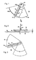
- FIGS. 1 to 3 is denoted by the reference numeral 10 to a predetermined length L * tailored, ie cut to length sintered metal blank, which consists for example of a hard metal powder with kneaded binding or adhesive.
- This sintered metal blank is produced for example by extrusion, in such a way that it has a straight and continuous, shown in the figures with dotted line inner recess 12 which extends parallel to the center axis 14 of the circular cylindrical blank 10.
- the production of the sintered metal blank is preferably carried out in the extrusion process with the aid of an extrusion die with a suitable core.
- the blank 10 has a relatively soft consistency, so that the handling, such. As the transport, must be done very carefully to prevent irreversible deformation. Therefore, the blank is preferably performed immediately after exiting the extrusion die on an air cushion and directed to the pad 16 shown in the figures, which in the FIGS. 1 and 3 coincides with the presentation plane.
- the blank is due to the consistency of the extruded mass on its outside sticky, so that a good adhesion with the support surface 16 results.
- a circular segment disc 18 with a bottom-side friction surface 20 is arranged.
- the circular segment disc 18 is rotatable about an axis of rotation 22 which is perpendicular to the surface of the support 16 and on the friction surface.
- the vertical distance AV between the surfaces 16 and 20 is preferably adjustable, which is indicated by the double arrow V in FIG. 2 is indicated. This vertical distance AV corresponds to the diameter D of the blank 10.
- the blank 10 is placed on the support 16 so that its longitudinal axis 14, the axis of rotation 22 of the circular segment disc 18 cuts. Subsequently, the circular segment disc is lowered controlled so that it touches the blank 10 along a line which is offset diametrically to the bottom-side contact line of the blank 10 with the support 16. This alignment is in the Figures 1 and 2 shown.
- the circular segment disc 18 is pivoted at an angular velocity ⁇ . Due to the frictional contact between the surface 20 of the circular segment disc 18 and the blank 10 of the blank is taken by rolling on the surface of the support 16 at a speed that changes linearly and steadily along the axis of the blank 10.
- the rolling speed at the inner end of the blank 10 is VWI and the rolling speed at the outer end of the blank 10 is designated VWA.
- the circular segment disc 18 is held in contact with the rod-shaped blank 10 with as little contact force as possible, specifically during the entire twisting operation, ie during the entire pivoting about the pivoting angle ⁇ (see FIG. Fig. 3 ).
- a change in the axis of rotation in contrast to the reference to the FIGS. 1 to 3 described prior art during the rolling process, a change in the axis of rotation.
- This change in the axis of rotation takes place in particular such that all longitudinal sections of the blank during the rolling process each cover the same rolling distance.
- the rolling process takes place in two successive steps, wherein in the first step, a rolling movement about a first axis of rotation and in the second step, a rolling movement about a second axis of rotation takes place.
- a method according to the invention serves as well as that of EP-B1-1 230 046 known method for producing a circular cylindrical body consisting of plastic mass, in particular a sintered metal blank, which has at least one helical inner recess running in the interior of the body.
- the body is as well as in the EP-B1-1 230 046 known method initially prepared with a straight course of the inner recess, for example extruded.
- the extruded body is cut to a desired length. Subsequently, it is subjected to a rolling process with support over its entire length on a support with a friction surface arrangement, so that a twisting of the body takes place.
- the rolling process takes place in two successive steps, wherein in the first step, a rolling movement about a first axis of rotation and in the second step, a rolling movement about a second axis of rotation, wherein the second axis of rotation is different from the first axis of rotation.
- the rolling process takes place in such a way that each longitudinal section of the circular-cylindrical body travels the same path during the rolling process. The Rolling direction is maintained in the successive steps.
- the positioning of the axes of rotation is such that during the first step, the axis of rotation intersects the center line of the circular cylindrical body in the region of an axial end surface of the circular cylindrical body and during the second step, the axis of rotation of the center line of the circular cylindrical body in the area the other axial end surface of the circular cylindrical body intersects.
- the positioning of the axes of rotation is such that during the first step, the axis of rotation intersects the extended centerline of the circular cylindrical body at a predetermined distance from an axial end surface of the circular cylindrical body and during the second step the axis of rotation extends Center line of the circular cylindrical body at the same predetermined distance from the other axial end surface of the circular cylindrical body intersects.
- Another embodiment of the invention is to change the axis of rotation about which the rolling movement occurs during the rolling movement several times or continuously.
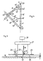
- FIG. 4 shows a sketch to illustrate the change of the axis of rotation during the rolling process.
- the circular cylindrical body 10 is in the position in which it is represented by the reference numeral 10.
- a twisting of the body using the Rotation axis D1 which runs perpendicular to the plane of the drawing.
- the body is moved through an angle in the FIG. 4 in the vicinity of the rotation axis D1 is denoted by "a".
- the rotation axis D1 intersects the center line M of the circular cylindrical body at a predetermined distance from an axial end portion of the circular cylindrical body.
- the velocity changes linearly and steadily over the length of the body.
- the body is in a position offset by the angle ⁇ . He is there with the reference numeral 10 'provided.
- a second step the body is twisted using a rotation axis D2. This also runs perpendicular to the drawing plane.
- the rotation axis D2 intersects the center line M 'of the circular cylindrical body 10' at a predetermined distance from the other axial end surface of the circular cylindrical body.
- the body is moved through an angle, which in the FIG. 4 in the vicinity of the rotation axis D2 is also denoted by " ⁇ ". Even with this twisting, the speed changes linearly and steadily over the length of the body.
- the body is in a position offset by the angle ⁇ . He is there with the reference numeral 10 "provided.
- the entire twisting process is tuned to the effect that the different longitudinal sections of the circular cylindrical body cover the same distance or twisting distance during the entire twisting process. This is in the FIG. 4 illustrated by the longitudinal sections A1 and A2 of the circular cylindrical body.
- the longitudinal section A1 of the circular cylindrical body is in the first step to those in the FIG. 4 moved with s1 path. After completion of the first step this longitudinal section is located in the body 10 'and is designated there by A1'.
- FIG. 5 shows a sketch to illustrate a device for carrying out the method according to the invention.
- This device has a flat support surface 16.
- a Wälzin 23 is arranged in the vertical distance AV to this .
- This has a pad surface side friction surface 24.
- the Wälzin 23 is rotatable about an axis of rotation 25 which is perpendicular to the surface of the support surface 16. This rotation takes place at an angular velocity ⁇ .
- the vertical distance AV between the support surface 16 and the Wälzsay 23 is adjustable, as indicated by the double arrow V.
- the rolling movement takes place using the axis of rotation 25.
- the rolling movement takes place using a second axis of rotation 26, which is also perpendicular to the surface of the support surface 16.
- This rotation also takes place at the angular velocity ⁇ .
- the rolling direction in the second step coincides with the rolling direction in the first step.
Abstract
Description
Die Erfindung bezieht sich auf ein Verfahren und eine Vorrichtung zur Herstellung eines aus plastischer Masse bestehenden kreiszylindrischen Körpers, insbesondere eines Sintermetall-Rohlings, der mindestens eine im Inneren des Körpers verlaufende wendelförmige Innenausnehmung hat, gemäß dem Oberbegriff des Patentanspruchs 1 bzw. des Patentanspruchs 7.The invention relates to a method and an apparatus for producing a circular-cylindrical body consisting of plastic mass, in particular a sintered metal blank, which has at least one helical inner recess extending in the interior of the body, according to the preamble of patent claim 1 or claim 7.
Solche Körper werden insbesondere bei der Herstellung von Bohrwerkzeugen bzw. Bohrwerkzeug-Einsätzen aus Hartmetall oder keramischen Werkstoffen benötigt. Durch den wendelförmigen Verlauf der zumindest einen Innenausnehmung, die beim fertigen Bohrwerkzeug zur Zufuhr von Kühl- oder Schmiermittel in den Schneidenbereich dient, kann das Bohrwerkzeug mit wendelförmigen Spannuten ausgestattet werden, was oftmals zur Bereitstellung günstiger Schnitt-und Zerspanungseigenschaften von Vorteil und deshalb angestrebt ist.Such bodies are needed in particular in the production of drilling tools or drilling tool inserts made of hard metal or ceramic materials. Due to the helical course of the at least one inner recess, which serves in the finished drilling tool for the supply of coolant or lubricant in the cutting area, the drilling tool can be equipped with helical flutes, which is often sought to provide favorable cutting and machining properties of advantage and therefore.
Man hat bereits frühzeitig versucht, solche Sintermetall-oder Keramikrohlinge im Extrusionsverfahren herzustellen, indem die aus Sintermetallpulver bzw. Keramikpulver und Bindemittel bestehende Masse durch eine Pressdüse gedrückt wird, die einen dem anzustrebenden Rohlingsquerschnitt entsprechenden Querschnitt und zumindest einen innenliegenden Kern in Form eines Stifts hat, der beim Extrudieren der plastifizierten Masse für die Bildung der sich durch den gesamten Rohling erstreckenden Innenausnehmung dient.It has already been attempted at an early stage to produce such sintered metal or ceramic blanks in the extrusion process by pressing the mass consisting of sintered metal powder or ceramic powder and binder through a pressing die having a cross section corresponding to the desired blank cross section and at least one inner core in the form of a pin, when extruding the plasticized mass for the formation of the is used by the entire blank extending inner recess.
Die aus der Pressdüse austretende Masse ist in der Regel sehr druckempfindlich, d. h. der austretende Rohling verformt sich bei äußerer Krafteinwirkung äußerst leicht. Da solche Verformungen nicht mehr reversibel sind und damit zu zumindest abschnittsweise unbrauchbaren Rohlingen führen, hat man versucht, das Extrusionsverfahren so weiter zu entwickeln, dass der Rohling bereits beim Austreten aus der Strangpressdüse wendelförmig verlaufende Kühlkanäle aufweist. Gemäß einem Vorschlag (siehe z. B.
Gemäß einem weiteren Vorschlag wird das Düsenmundstück und/oder eine propellerartig gestaltete Nabe, an der die vorstehend genannten flexiblen bzw. biegeschlaffen Fäden befestigt sind, während des Extrusionsvorgangs in Drehbewegung versetzt, wodurch wiederum ein außenseitig glatter Rohling mit innenliegenden wendelförmigen Kanälen bzw. Ausnehmungen hergestellt werden kann.According to a further proposal, the nozzle mouthpiece and / or a hub shaped like a propeller, to which the abovementioned flexible limbs are fastened, are set into rotary motion during the extrusion process, which in turn produces an outer smooth blank with inner helical channels or recesses can.
Bei der Herstellung solcher Werkzeug-Rohlinge kommt es darauf an, dass der Steigungswinkel der zumindest einen wendelförmigen Innenausnehmung über die gesamte Länge des Rohlings konstant und innerhalb eng tolerierter Grenzen gehalten wird. Dies ist deshalb erforderlich, weil in den Werkzeugrohling nach dem Sinterprozess regelmäßig Spannuten eingeschliffen werden. Dieses Einschleifen erfolgt mit weitgehend automatisierten Maschinen, so dass sich bei ungenauer Herstellung der wendelförmigen Innenausnehmungen eine unkontrolliert hohe Ausschussrate ergeben kann. Dabei ist zu berücksichtigen, dass Werkzeuge mit Vollhartmetall-Schneidteilen unter anderem deshalb eingesetzt werden, weil die hohe Beanspruchbarkeit des Werkstoffs, insbesondere die Torsionssteifigkeit, ausgenützt werden soll. Um dies sicherzustellen, darf die Innenausnehmung nicht zu nahe an die Spannut heran reichen, was bei ungenauer Herstellung der wendelförmigen Innenausnehmung jedoch nicht wirksam ausgeschlossen werden kann.In the production of such tool blanks, it is important that the pitch angle of the at least one helical inner recess over the entire length of the blank is kept constant and within narrow tolerance limits. This is necessary because in the Tool blank are regularly ground flutes after the sintering process. This grinding is done with largely automated machines, so that an uncontrolled high rejection rate can result from inaccurate production of helical inner recesses. It should be noted that tools are used with solid carbide cutting parts, inter alia, because the high strength of the material, in particular the torsional stiffness, to be exploited. To ensure this, the inner recess must not reach too close to the flute zoom, which can not be effectively excluded inaccurate production of the helical inner recess.
Bei den vorstehend beschriebenen Ansätzen zur Herstellung des Rohlings mit innneliegenden wendelförmigen Ausnehmungen ist es deshalb erforderlich, das Extrusionswerkzeug und/oder die Sintereinrichtungen für die Extrusionsschnecke bzw. - falls vorhanden - für die drallerzeugenden Körper beim Extrusionsvorgang genauestens zu überwachen und auf den Massendurchsatz abzustimmen. Dies hat zur Folge, dass verhältnismäßig lange Umrüst- und Einstellzeiten am Strangpresswerkzeug erforderlich sind, mit der Folge, dass herkömmliche Verfahren wirtschaftlich in erster Linie für große Serien Anwendung finden. Für kleine Serien bzw. für die Herstellung von Bohrwerkzeugen mit größeren Nenndurchmessern ergeben sich unverhältnismäßig hohe Maschinen-Einstellkosten, wodurch die Wirtschaftlichkeit des Herstellungsverfahrens in Frage gestellt wird.In the approaches described above for producing the blank with innnecting helical recesses, it is therefore necessary to closely monitor the extrusion tool and / or the sintering devices for the extrusion screw or, if present, for the swirl-producing bodies in the extrusion process and to match the mass flow rate. As a result, relatively long retooling and setting times are required on the extrusion tool, with the result that conventional methods are used economically primarily for large series. For small series or for the production of drilling tools with larger nominal diameters result disproportionately high machine setting costs, whereby the efficiency of the manufacturing process is called into question.
Aus der
Mittels des aus der
In der Praxis bestehen zunehmend höhere Anforderungen an die Konstanthaltung des Steigungswinkels der zumindest einen wendelförmigen Innenausnehmung über die gesamte Länge des Rohlings innerhalb eng tolerierter Grenzen.In practice, there are increasingly greater demands on the constant maintenance of the pitch angle of the at least one helical inner recess over the entire length of the blank within tight tolerances.
Die Aufgabe der Erfindung besteht deshalb darin, ein Verfahren und eine Vorrichtung zur Herstellung eines aus plastischer Masse bestehenden kreiszylindrischen Körpers anzugeben, das bzw. die diesen höheren Anforderungen gerecht wird.The object of the invention is therefore to provide a method and an apparatus for producing a circular mass consisting of plastic mass body, which is or these higher requirements.
Diese Aufgabe wird durch ein Verfahren mit den im Anspruch 1 angegebenen Merkmalen gelöst. Vorteilhafte Weiterbildungen sind in den abhängigen Ansprüchen 2 bis 6 angegeben. Der Anspruch 7 hat eine Vorrichtung zur Herstellung eines aus plastischer Masse bestehenden kreiszylindrischen Körpers zum Gegenstand. Die abhängigen Ansprüche 8 bis 12 betreffen vorteilhafte Ausgestaltungen und Weiterbildungen der im Anspruch 7 angegebenen Vorrichtung.This object is achieved by a method having the features specified in claim 1. Advantageous developments are specified in the dependent claims 2 to 6. The claim 7 has an apparatus for producing a circular mass consisting of plastic body. The dependent claims 8 to 12 relate to advantageous embodiments and further developments of the device specified in claim 7.
Die Vorteile der Erfindung bestehen insbesondere darin, dass mittels des beanspruchten Verfahrens aus plastischer Masse bestehende kreiszylindrische Körper hergestellt werden können, deren zumindest eine wendelförmige Innenausnehmung über die gesamte Länge des Körpers einen äuβerst konstanten, innerhalb sehr eng tolerierter Grenzen gehaltenen Steigungswinkel aufweist. Dieser Vorteil beruht darauf, dass die einzelnen Längsabschnitte des kreiszylindrischen Körpers während des Wälzvorgangs jeweils denselben Weg zurücklegen. Im Unterschied dazu legen bei dem aus der
Weitere vorteilhafte Eigenschaften der Erfindung ergeben sich aus deren beispielhafter Erläuterung anhand der Figuren. Es zeigt
- Figur 1
- eine Draufsicht einer Ausführungsform einer Vorrichtung zur Herstellung eines aus einer plastischen Masse bestehenden Sintermetall- Rohlings mit einer innenliegenden Ausnehmung nach dem Stand der Technik,
- Figur 2
- die Ansicht entsprechend II in
FIG 1 , - Figur 3
- in einer der
FIG 1 entsprechenden Ansicht die Vorrichtung nach der Verdrillung des extrudier- ten Rohlings, - Figur 4
- eine Skizze zur Veranschaulichung der Änderung der Drehachse während der Wälzbewegung beim er- findungsgemäßen Verfahren und
- Figur 5
- eine Skizze zur Veranschaulichung einer Vor- richtung zur Durchführung des erfindungsgemäßen Verfahrens.
- FIG. 1
- a top view of an embodiment of an apparatus for producing a plastic mass sintered metal blank having an inner recess according to the prior art,
- FIG. 2
- the view corresponding to II in
FIG. 1 . - FIG. 3
- in one of the
FIG. 1 corresponding view of the device after the twisting of the extruded blank, - FIG. 4
- a sketch to illustrate the change of the axis of rotation during the rolling motion in the inventive method and
- FIG. 5
- a sketch illustrating an apparatus for carrying out the method according to the invention.
In den
Die Herstellung des Sintermetall-Rohlings erfolgt vorzugsweise im Extrusionsverfahren unter Zuhilfenahme einer Strangpressdüse mit geeignetem Kern. Der Rohling 10 hat eine verhältnismäßig weiche Konsistenz, so dass die Handhabung, wie z. B. der Transport, sehr vorsichtig erfolgen muss, um irreversible Verformungen zu verhindern. Deshalb wird der Rohling vorzugsweise unmittelbar nach dem Austritt aus der Strangpressdüse auf einem Luftkissen geführt und auf die in den Figuren gezeigte Unterlage 16 geleitet, die in den
Um den Rohling 10 derart umzuformen, dass die geradlinige Innenausnehmung gemäß
Parallel zur ebenen Auflagefläche 16 im Vertikalabstand AV ist eine Kreissegmentscheibe 18 mit einer bodenseitigen Reibungsfläche 20 angeordnet. Die Kreissegmentscheibe 18 ist um eine Drehachse 22 drehbar, die auf der Oberfläche der Auflage 16 bzw. auf der Reibungsfläche senkrecht steht. Der Vertikalabstand AV zwischen den Flächen 16 und 20 ist vorzugsweise einstellbar, was durch den Doppelpfeil V in
Wie in
Nun wird die Kreissegmentscheibe 18 mit einer Winkelgeschwindigkeit ωverschwenkt. Durch den Reibkontakt zwischen der Oberfläche 20 der Kreissegmentscheibe 18 und dem Rohling 10 wird der Rohling mitgenommen, indem er auf der Fläche der Auflage 16 mit einer Geschwindigkeit abwälzt, die sich entlang der Achse des Rohlings 10 linear und stetig ändert. Die Wälzgeschwindigkeit am inneren Ende des Rohlings 10 ist mit VWI und die Wälzgeschwindigkeit am äußeren Ende des Rohlings 10 ist mit VWA bezeichnet. Wenn somit die Segmentscheibe 18 einen bestimmten Verschenkwinkel ϕ durchläuft, ergibt sich entlang des stabförmigen Rohlings 10 eine lineare Verteilung der Wälzstrecke, mit der Folge, dass der kreiszylindrische Rohling 10 während der Wälzbewegung verdrillt wird, und zwar derart, dass sich ein Steigungswinkel der Verdrillung und damit ein Steigungswinkel der wendelförmigen Innenausnehmung 12 ergibt, der direkt proportional zum Verschwenkwinkel ϕ ist.Now, the
Vorzugsweise wird die Kreissegmentsscheibe 18 mit möglichst geringer Auflagekraft in Kontakt mit dem stabförmigen Rohling 10 gehalten, und zwar während des gesamten Verdrillvorgangs, d. h. während der gesamten Verschwenkung um den Verschwenkwinkel ϕ (s.
Aus der vorstehenden Beschreibung und den
Dieser Nachteil wird durch eine Verwendung eines Verfahrens gemäß der vorliegenden Erfindung vermieden. Bei der vorliegenden Erfindung erfolgt im Unterschied zu dem anhand der
Ein Verfahren gemäß der Erfindung dient ebenso wie das aus der
Bei einem Verfahren gemäß der Erfindung wird der Körper ebenso wie bei dem aus der
Im Unterschied zu dem aus der
Vorzugsweise erfolgt der Wälzvorgang in zwei aufeinanderfolgenden Schritten, wobei im ersten Schritt eine Wälzbewegung um eine erste Drehachse und im zweiten Schritt eine Wälzbewegung um eine zweite Drehachse erfolgt, wobei die zweite Drehachse von der ersten Drehachse verschieden ist. In ihrer Gesamtheit erfolgt der Wälzvorgang derart, dass jeder Längsabschnitt des kreiszylindrischen Körpers während des Wälzvorgangs denselben Weg zurücklegt. Die Wälzrichtung wird in den aufeinanderfolgenden Schritten beibehalten.Preferably, the rolling process takes place in two successive steps, wherein in the first step, a rolling movement about a first axis of rotation and in the second step, a rolling movement about a second axis of rotation, wherein the second axis of rotation is different from the first axis of rotation. In its entirety, the rolling process takes place in such a way that each longitudinal section of the circular-cylindrical body travels the same path during the rolling process. The Rolling direction is maintained in the successive steps.
Gemäß einer ersten Ausführungsform des erfindungsgemäßen Verfahrens erfolgt die Positionierung der Drehachsen derart, dass während des ersten Schrittes die Drehachse die Mittellinie des kreiszylindrischen Körpers im Bereich einer axialen Endfläche des kreiszylindrischen Körpers schneidet und dass während des zweiten Schrittes die Drehachse die Mittellinie des kreiszylindrischen Körpers im Bereich der anderen axialen Endfläche des kreiszylindrischen Körpers schneidet.According to a first embodiment of the method according to the invention, the positioning of the axes of rotation is such that during the first step, the axis of rotation intersects the center line of the circular cylindrical body in the region of an axial end surface of the circular cylindrical body and during the second step, the axis of rotation of the center line of the circular cylindrical body in the area the other axial end surface of the circular cylindrical body intersects.
Gemäß einer zweiten, bevorzugten Ausführungsform des erfindungsgemäßen Verfahrens erfolgt die Positionierung der Drehachsen derart, dass während des ersten Schrittes die Drehachse die verlängerte Mittellinie des kreiszylindrischen Körpers in einer vorgegebenen Entfernung von einer axialen Endfläche des kreiszylindrischen Körpers schneidet und während des zweiten Schrittes die Drehachse die verlängerte Mittellinie des kreiszylindrischen Körpers in derselben vorgegebenen Entfernung von der anderen axialen Endfläche des kreiszylindrischen Körpers schneidet.According to a second preferred embodiment of the method according to the invention, the positioning of the axes of rotation is such that during the first step, the axis of rotation intersects the extended centerline of the circular cylindrical body at a predetermined distance from an axial end surface of the circular cylindrical body and during the second step the axis of rotation extends Center line of the circular cylindrical body at the same predetermined distance from the other axial end surface of the circular cylindrical body intersects.
Eine weitere Ausführungsform der Erfindung besteht darin, die Drehachse, um welche die Walzbewegung erfolgt, während der Walzbewegung mehrmals oder auch kontinuierlich zu verändern.Another embodiment of the invention is to change the axis of rotation about which the rolling movement occurs during the rolling movement several times or continuously.
Die
Zu Beginn des Wälzvorgangs befindet sich der kreiszylindrische Körper 10 in der Position, in der er mit der Bezugszahl 10 dargestellt ist.At the beginning of the rolling process, the circular
Ausgehend von dieser Position erfolgt in einem ersten Schritt ein Verdrillen des Körpers unter Verwendung der Drehachse D1, die senkrecht zur Zeichenebene verläuft. Während dieses ersten Schrittes wird der Körper um einen Winkel bewegt, der in der
Anschließend erfolgt in einem zweiten Schritt ein Verdrillen des Körpers unter Verwendung einer Drehachse D2. Diese verläuft ebenfalls senkrecht zur Zeichenebene. Die Drehachse D2 schneidet die Mittellinie M' des kreiszylindrischen Körpers 10' in einem vorgegebenen Abstand von der anderen axialen Endfläche des kreiszylindrischen Körpers. In diesem zweiten Schritt wird der Körper um einen Winkel bewegt, der in der
Der gesamte Verdrillvorgang ist dahingehend abgestimmt, dass die verschiedenen Längsabschnitte des kreiszylindrischen Körpers während des gesamten Verdrillvorgangs jeweils dieselbe Wegstrecke bzw. Verdrillstrecke zurücklegen. Dies ist in der
Der Längsabschnitt A1 des kreiszylindrischen Körpers wird im ersten Schritt um die in der
Im zweiten Schritt wird der Längsabschnitt Al' um die in der 
Der Längsabschnitt A2 des kreiszylindrischen Körpers wird im ersten Schritt um die in der 
Es gilt: ![]()
![]()
Folglich durchlaufen während eines kompletten Verdrillvorgangs alle Längsabschnitte des kreiszylindrischen Körpers dieselbe gesamte Wegstrecke. Dies hat in vorteilhafter Weise zur Folge, dass der Anstiegswinkel der mindestens einen im Inneren des Körpers verlaufenden wendelförmigen Innenausnehmung über die gesamte Länge des kreiszylindrischen Körpers eine im Vergleich zum bekannten Verfahren erhöhte Steigungsgenauigkeit aufweist. Dies reduziert den beim späteren Einschleifen von Spannuten entstehenden Ausschuss bzw. reduziert die Anforderung an die Arbeitsgenauigkeit beim Verdrillen.Consequently, during a complete twisting operation, all longitudinal sections of the circular cylindrical body travel the same entire distance. This advantageously has the consequence that the angle of rise of the at least one helical inner recess extending in the interior of the body over the entire length of the circular-cylindrical body has an increased pitch accuracy in comparison with the known method. This reduces the resulting later grinding of flutes Rejects or reduces the requirement for working accuracy during twisting.
Die
Claims (12)
- Method of producing a circularly cylindrical body (10), which consists of plastics material and which has at least one helical internal recess (12) extending in the interior of the body, wherein the body is initially produced with a rectilinear course of the internal recess and the body, which is cut to a specific length, is subsequently subjected to a rolling process, while being supported over its entire length on a support (16), by means of a friction surface arrangement (23), which similarly engages over the entire length of the body, with a friction surface (24) arranged parallel to the support, characterised in that the rolling process is carried out in several steps, wherein in a first step a rolling movement is carried out with use of a first axis (25) of rotation of the friction surface arrangement and in a second step a rolling movement is carried out with use of a second axis (26) of rotation, which is different from the first axis of rotation, of the friction surface arrangement, wherein the axes of rotation extend perpendicularly to the support or to the friction surface.
- Method according to claim 1, characterised in that the axis of rotation of the friction surface arrangement about which the rolling movement is carried out is changed a number of times or continuously during the rolling movement.
- Method according to claim 1 or 2, characterised in that each length section of the circularly cylindrical body covers the same path during the rolling process.
- Method according to any one of the preceding claims, characterised in that the rolling direction is maintained in the several steps.
- Method according to any one of the preceding claims, characterised in that during the first step the first axis of rotation of the friction surface arrangement intersects the centre line of the circularly cylindrical body in the region of one axial end surface of the circularly cylindrical body and during the second step the second axis of rotation of the friction surface arrangement intersects the centre line of the circularly cylindrical body in the region of the other axial end surface of the circularly cylindrical body.
- Method according to any one of claims 1 to 4, characterised in that during the first step the first axis of rotation of the friction surface arrangement intersects the prolonged centre line of the circularly cylindrical body at a predetermined distance from one axial end surface of the circularly cylindrical body and during the second step the second axis of rotation of the friction surface arrangement intersects the prolonged centre line of the circularly cylindrical body at the predetermined distance from the other axial end surface of the circularly cylindrical body.
- Device for performing a method according to any one of the preceding claims, with a support surface (16) for supporting the body (10) over the entire length thereof, a friction surface arrangement (23), which engages the body similarly over the entire length thereof, with a friction surface (24) arranged parallel to the support and a drive unit (27) by which the friction surface arrangement is subjected to a movement producing a rolling process at the body, characterised in that the friction surface arrangement (23) is rotatable about a first axis (25) of rotation and about a second axis (26) of rotation, wherein the axes of rotation extend perpendicularly to the support or to the friction surface arrangement.
- Device according to claim 7, characterised in that it comprises a control unit (28) which supplies control signals to the drive unit (27).
- Device according to claim 8, characterised in that the control unit (28) generates the control signals for the drive unit (27) in such a way that in a first step of the rolling process the friction surface arrangement is rotated about the first axis (25) of rotation and in a second step of the rolling process the friction surface arrangement is rotated about the second axis (26) of rotation.
- Device according to claim 9, characterised in that the control unit (28) generates the control signals for the drive unit (27) in such a way that the rotation of the friction surface arrangement in the first step and the rotation of the friction surface arrangement in the second step take place at the same angular speed (ω).
- Device according to claim 9 or 10, characterised in that the control unit (28) generates the control signals for the drive unit (27) in such a way that the rotation of the friction surface arrangement in the first step and the rotation of the friction surface arrangement in the second step take place through the same size angle.
- Device according to any one of claims 9 to 11, characterised in that the control unit (28) generates the control signals for the drive unit (27) in such a way that the rolling direction is maintained in the first step and in the second step.
Applications Claiming Priority (2)
| Application Number | Priority Date | Filing Date | Title |
|---|---|---|---|
| DE102008033413A DE102008033413A1 (en) | 2008-07-16 | 2008-07-16 | Method and device for producing a circular-cylindrical body consisting of plastic mass with internal helical recesses |
| PCT/EP2009/057583 WO2010006873A1 (en) | 2008-07-16 | 2009-06-18 | Method and apparatus for producing a circular cylindrical body comprising a workable mass and having internal helical recesses |
Publications (2)
| Publication Number | Publication Date |
|---|---|
| EP2313218A1 EP2313218A1 (en) | 2011-04-27 |
| EP2313218B1 true EP2313218B1 (en) | 2011-10-19 |
Family
ID=41066151
Family Applications (1)
| Application Number | Title | Priority Date | Filing Date |
|---|---|---|---|
| EP09779827A Active EP2313218B1 (en) | 2008-07-16 | 2009-06-18 | Method and apparatus for producing a circular cylindrical body comprising a workable mass and having internal helical recesses |
Country Status (9)
| Country | Link |
|---|---|
| US (2) | US8850861B2 (en) |
| EP (1) | EP2313218B1 (en) |
| JP (1) | JP5453414B2 (en) |
| KR (1) | KR101264755B1 (en) |
| CN (1) | CN102099134B (en) |
| AT (1) | ATE529206T1 (en) |
| DE (1) | DE102008033413A1 (en) |
| ES (1) | ES2373634T3 (en) |
| WO (1) | WO2010006873A1 (en) |
Cited By (1)
| Publication number | Priority date | Publication date | Assignee | Title |
|---|---|---|---|---|
| WO2019057351A1 (en) | 2017-09-21 | 2019-03-28 | Arno Friedrichs | Method and device for producing a circular-cylindrical body consisting of a plastic compound |
Families Citing this family (2)
| Publication number | Priority date | Publication date | Assignee | Title |
|---|---|---|---|---|
| DE102014115760A1 (en) | 2014-10-30 | 2016-05-04 | Arno Friedrichs | Cutting tool with internal spirally running coolant channels with changing pitch angle |
| CN109249026A (en) * | 2018-11-12 | 2019-01-22 | 深圳艾利佳材料科技有限公司 | A kind of moulding process squeezing out rolling with powder |
Family Cites Families (10)
| Publication number | Priority date | Publication date | Assignee | Title |
|---|---|---|---|---|
| EP0173675A1 (en) | 1984-08-28 | 1986-03-05 | Vereinigte Edelstahlwerke Aktiengesellschaft (Vew) | Method and device for producing especially metallic work pieces, preferably from steel |
| JPH0663003B2 (en) | 1989-09-08 | 1994-08-17 | 東芝タンガロイ株式会社 | Extrusion molding machine |
| DE4120165C2 (en) | 1990-07-05 | 1995-01-26 | Friedrichs Konrad Kg | Extrusion tool for producing a hard metal or ceramic rod |
| JPH04198404A (en) | 1990-11-28 | 1992-07-17 | Kobe Steel Ltd | Production of hard long raw material with hole |
| JPH04198405A (en) | 1990-11-28 | 1992-07-17 | Kobe Steel Ltd | Production of hard long raw material with hole |
| JPH04210407A (en) | 1990-11-30 | 1992-07-31 | Kobe Steel Ltd | Manufacture of drill and end mill with oil hole |
| US5152061A (en) | 1992-02-19 | 1992-10-06 | Tesma International Inc. | Cold-forming of toothed wheels from sheet steel |
| CN1133515C (en) | 1999-09-09 | 2004-01-07 | 阿尔诺·弗里德里克斯 | Method and device for producing sintered metal blank with interior helical recesses |
| DE10356111B4 (en) * | 2003-11-27 | 2006-10-12 | Zf Friedrichshafen Ag | Cold forming process for the production of one-piece ball studs |
| CN1974054A (en) * | 2006-12-08 | 2007-06-06 | 青特集团有限公司 | Slender stepped shaft machining process |
-
2008
- 2008-07-16 DE DE102008033413A patent/DE102008033413A1/en not_active Withdrawn
-
2009
- 2009-06-18 JP JP2011517837A patent/JP5453414B2/en active Active
- 2009-06-18 CN CN2009801273681A patent/CN102099134B/en active Active
- 2009-06-18 ES ES09779827T patent/ES2373634T3/en active Active
- 2009-06-18 AT AT09779827T patent/ATE529206T1/en active
- 2009-06-18 EP EP09779827A patent/EP2313218B1/en active Active
- 2009-06-18 KR KR1020117001088A patent/KR101264755B1/en active IP Right Grant
- 2009-06-18 US US12/737,444 patent/US8850861B2/en active Active
- 2009-06-18 WO PCT/EP2009/057583 patent/WO2010006873A1/en active Application Filing
-
2014
- 2014-08-28 US US14/471,318 patent/US9044797B2/en active Active
Cited By (1)
| Publication number | Priority date | Publication date | Assignee | Title |
|---|---|---|---|---|
| WO2019057351A1 (en) | 2017-09-21 | 2019-03-28 | Arno Friedrichs | Method and device for producing a circular-cylindrical body consisting of a plastic compound |
Also Published As
| Publication number | Publication date |
|---|---|
| KR101264755B1 (en) | 2013-05-15 |
| CN102099134B (en) | 2013-05-22 |
| EP2313218A1 (en) | 2011-04-27 |
| KR20110031950A (en) | 2011-03-29 |
| ES2373634T3 (en) | 2012-02-07 |
| US20110113846A1 (en) | 2011-05-19 |
| US20150027188A1 (en) | 2015-01-29 |
| WO2010006873A1 (en) | 2010-01-21 |
| ATE529206T1 (en) | 2011-11-15 |
| DE102008033413A1 (en) | 2010-01-21 |
| US9044797B2 (en) | 2015-06-02 |
| CN102099134A (en) | 2011-06-15 |
| JP5453414B2 (en) | 2014-03-26 |
| US8850861B2 (en) | 2014-10-07 |
| JP2011527943A (en) | 2011-11-10 |
Similar Documents
| Publication | Publication Date | Title |
|---|---|---|
| EP0465946B1 (en) | Hard metal or ceramic bar, method and extrusion-die for its production | |
| EP1017527B1 (en) | Continuous extrusion process and device for rods made of a plastic raw material and provided with a spiral inner channel | |
| DE4120166A1 (en) | EXTRACTION TOOL FOR PRODUCING A HARD METAL OR CERAMIC BAR WITH TWISTED INTERNAL HOLES | |
| DE102014108219A1 (en) | Rotary tool and method for producing a rotary tool | |
| EP2127777A1 (en) | Device and method for generating or processing workpieces from a blank mould, in particular for casting internal profiles or internal gears | |
| EP1340573A1 (en) | Manufacturing method for a drill bit or for a milling tool | |
| EP1230046B1 (en) | Method and device for producing a sintered metal blank with interior helical recesses | |
| EP0458774B2 (en) | Hard metal, or ceramics, blank and method and tool for manufacture of same | |
| DE102005019921A1 (en) | Tool for producing or re-machining threads, has thread-forming teeth with thread-forming profiles that protrude outwards from carrier body | |
| EP2313218B1 (en) | Method and apparatus for producing a circular cylindrical body comprising a workable mass and having internal helical recesses | |
| EP4076812A1 (en) | Twist drill bit having a cutting tip with a stepped structure | |
| DE2808081A1 (en) | METHOD AND DEVICE FOR MANUFACTURING HELICAL ROTOR BLANKS FOR Eccentric Screw Pumps | |
| DE19942966C2 (en) | Method and device for producing a sintered metal blank with internal, helical recesses | |
| DE10229325B4 (en) | Extrusion tool for producing a cylindrical body consisting of plastic mass | |
| EP3684585B1 (en) | Method and device for producing a circular-cylindrical body consisting of a plastic compound | |
| DE102018202941B4 (en) | Process for producing a blank from extrusion mass and extruder | |
| EP2105292A1 (en) | Roller adjustment device | |
| DE4021383C2 (en) | Process for producing a hard metal or ceramic rod and extrusion tool for carrying out the process | |
| EP0634959B1 (en) | Process and device for the continuous production of cylindrical rods with at least one internal helical channel, and sinter blank made by this process | |
| DE4242336A1 (en) | Extrusion for cylindrical rods with at least one internal helical channel | |
| EP1347849B1 (en) | Flowspinning method and device for carrying out flowspinning | |
| DE4211827C2 (en) | Method and extrusion tool for the continuous production of cylindrical rods with at least one internal, helical channel, and rod produced by this method | |
| WO2004002642A1 (en) | Extrusion press tool for producing a cylindrical body consisting of a plastic mass | |
| EP1285706A1 (en) | Method of manufacturing a non-rotationally symmetrical workpiece without cutting and spinning machine | |
| DE10208633A1 (en) | Tool production method for making e.g. drill, milling cutter involves use of blank bar has diameter which is larger than diameter of conveying helix introduced in single operation |
Legal Events
| Date | Code | Title | Description |
|---|---|---|---|
| PUAI | Public reference made under article 153(3) epc to a published international application that has entered the european phase |
Free format text: ORIGINAL CODE: 0009012 |
|
| 17P | Request for examination filed |
Effective date: 20110216 |
|
| AK | Designated contracting states |
Kind code of ref document: A1 Designated state(s): AT BE BG CH CY CZ DE DK EE ES FI FR GB GR HR HU IE IS IT LI LT LU LV MC MK MT NL NO PL PT RO SE SI SK TR |
|
| AX | Request for extension of the european patent |
Extension state: AL BA RS |
|
| GRAP | Despatch of communication of intention to grant a patent |
Free format text: ORIGINAL CODE: EPIDOSNIGR1 |
|
| DAX | Request for extension of the european patent (deleted) | ||
| GRAS | Grant fee paid |
Free format text: ORIGINAL CODE: EPIDOSNIGR3 |
|
| GRAA | (expected) grant |
Free format text: ORIGINAL CODE: 0009210 |
|
| RAP1 | Party data changed (applicant data changed or rights of an application transferred) |
Owner name: FRIEDRICHS, ARNO |
|
| RIN1 | Information on inventor provided before grant (corrected) |
Inventor name: FRIEDRICHS, ARNO |
|
| AK | Designated contracting states |
Kind code of ref document: B1 Designated state(s): AT BE BG CH CY CZ DE DK EE ES FI FR GB GR HR HU IE IS IT LI LT LU LV MC MK MT NL NO PL PT RO SE SI SK TR |
|
| REG | Reference to a national code |
Ref country code: GB Ref legal event code: FG4D Free format text: NOT ENGLISH |
|
| REG | Reference to a national code |
Ref country code: CH Ref legal event code: EP |
|
| REG | Reference to a national code |
Ref country code: IE Ref legal event code: FG4D |
|
| REG | Reference to a national code |
Ref country code: CH Ref legal event code: NV Representative=s name: KELLER & PARTNER PATENTANWAELTE AG |
|
| REG | Reference to a national code |
Ref country code: DE Ref legal event code: R096 Ref document number: 502009001675 Country of ref document: DE Effective date: 20111229 |
|
| REG | Reference to a national code |
Ref country code: SE Ref legal event code: TRGR Ref country code: ES Ref legal event code: FG2A Ref document number: 2373634 Country of ref document: ES Kind code of ref document: T3 Effective date: 20120207 |
|
| REG | Reference to a national code |
Ref country code: NL Ref legal event code: VDEP Effective date: 20111019 |
|
| LTIE | Lt: invalidation of european patent or patent extension |
Effective date: 20111019 |
|
| PG25 | Lapsed in a contracting state [announced via postgrant information from national office to epo] |
Ref country code: IS Free format text: LAPSE BECAUSE OF FAILURE TO SUBMIT A TRANSLATION OF THE DESCRIPTION OR TO PAY THE FEE WITHIN THE PRESCRIBED TIME-LIMIT Effective date: 20120219 Ref country code: NO Free format text: LAPSE BECAUSE OF FAILURE TO SUBMIT A TRANSLATION OF THE DESCRIPTION OR TO PAY THE FEE WITHIN THE PRESCRIBED TIME-LIMIT Effective date: 20120119 Ref country code: LT Free format text: LAPSE BECAUSE OF FAILURE TO SUBMIT A TRANSLATION OF THE DESCRIPTION OR TO PAY THE FEE WITHIN THE PRESCRIBED TIME-LIMIT Effective date: 20111019 |
|
| PG25 | Lapsed in a contracting state [announced via postgrant information from national office to epo] |
Ref country code: PT Free format text: LAPSE BECAUSE OF FAILURE TO SUBMIT A TRANSLATION OF THE DESCRIPTION OR TO PAY THE FEE WITHIN THE PRESCRIBED TIME-LIMIT Effective date: 20120220 Ref country code: LV Free format text: LAPSE BECAUSE OF FAILURE TO SUBMIT A TRANSLATION OF THE DESCRIPTION OR TO PAY THE FEE WITHIN THE PRESCRIBED TIME-LIMIT Effective date: 20111019 Ref country code: GR Free format text: LAPSE BECAUSE OF FAILURE TO SUBMIT A TRANSLATION OF THE DESCRIPTION OR TO PAY THE FEE WITHIN THE PRESCRIBED TIME-LIMIT Effective date: 20120120 Ref country code: HR Free format text: LAPSE BECAUSE OF FAILURE TO SUBMIT A TRANSLATION OF THE DESCRIPTION OR TO PAY THE FEE WITHIN THE PRESCRIBED TIME-LIMIT Effective date: 20111019 Ref country code: SI Free format text: LAPSE BECAUSE OF FAILURE TO SUBMIT A TRANSLATION OF THE DESCRIPTION OR TO PAY THE FEE WITHIN THE PRESCRIBED TIME-LIMIT Effective date: 20111019 Ref country code: NL Free format text: LAPSE BECAUSE OF FAILURE TO SUBMIT A TRANSLATION OF THE DESCRIPTION OR TO PAY THE FEE WITHIN THE PRESCRIBED TIME-LIMIT Effective date: 20111019 |
|
| PG25 | Lapsed in a contracting state [announced via postgrant information from national office to epo] |
Ref country code: CY Free format text: LAPSE BECAUSE OF FAILURE TO SUBMIT A TRANSLATION OF THE DESCRIPTION OR TO PAY THE FEE WITHIN THE PRESCRIBED TIME-LIMIT Effective date: 20111019 |
|
| PG25 | Lapsed in a contracting state [announced via postgrant information from national office to epo] |
Ref country code: SK Free format text: LAPSE BECAUSE OF FAILURE TO SUBMIT A TRANSLATION OF THE DESCRIPTION OR TO PAY THE FEE WITHIN THE PRESCRIBED TIME-LIMIT Effective date: 20111019 Ref country code: BG Free format text: LAPSE BECAUSE OF FAILURE TO SUBMIT A TRANSLATION OF THE DESCRIPTION OR TO PAY THE FEE WITHIN THE PRESCRIBED TIME-LIMIT Effective date: 20120119 Ref country code: DK Free format text: LAPSE BECAUSE OF FAILURE TO SUBMIT A TRANSLATION OF THE DESCRIPTION OR TO PAY THE FEE WITHIN THE PRESCRIBED TIME-LIMIT Effective date: 20111019 Ref country code: CZ Free format text: LAPSE BECAUSE OF FAILURE TO SUBMIT A TRANSLATION OF THE DESCRIPTION OR TO PAY THE FEE WITHIN THE PRESCRIBED TIME-LIMIT Effective date: 20111019 Ref country code: EE Free format text: LAPSE BECAUSE OF FAILURE TO SUBMIT A TRANSLATION OF THE DESCRIPTION OR TO PAY THE FEE WITHIN THE PRESCRIBED TIME-LIMIT Effective date: 20111019 |
|
| PLBE | No opposition filed within time limit |
Free format text: ORIGINAL CODE: 0009261 |
|
| STAA | Information on the status of an ep patent application or granted ep patent |
Free format text: STATUS: NO OPPOSITION FILED WITHIN TIME LIMIT |
|
| PG25 | Lapsed in a contracting state [announced via postgrant information from national office to epo] |
Ref country code: RO Free format text: LAPSE BECAUSE OF FAILURE TO SUBMIT A TRANSLATION OF THE DESCRIPTION OR TO PAY THE FEE WITHIN THE PRESCRIBED TIME-LIMIT Effective date: 20111019 Ref country code: PL Free format text: LAPSE BECAUSE OF FAILURE TO SUBMIT A TRANSLATION OF THE DESCRIPTION OR TO PAY THE FEE WITHIN THE PRESCRIBED TIME-LIMIT Effective date: 20111019 |
|
| 26N | No opposition filed |
Effective date: 20120720 |
|
| REG | Reference to a national code |
Ref country code: DE Ref legal event code: R097 Ref document number: 502009001675 Country of ref document: DE Effective date: 20120720 |
|
| BERE | Be: lapsed |
Owner name: FRIEDRICHS, ARNO Effective date: 20120630 |
|
| PG25 | Lapsed in a contracting state [announced via postgrant information from national office to epo] |
Ref country code: MC Free format text: LAPSE BECAUSE OF NON-PAYMENT OF DUE FEES Effective date: 20120630 |
|
| PG25 | Lapsed in a contracting state [announced via postgrant information from national office to epo] |
Ref country code: MK Free format text: LAPSE BECAUSE OF FAILURE TO SUBMIT A TRANSLATION OF THE DESCRIPTION OR TO PAY THE FEE WITHIN THE PRESCRIBED TIME-LIMIT Effective date: 20111019 |
|
| PG25 | Lapsed in a contracting state [announced via postgrant information from national office to epo] |
Ref country code: BE Free format text: LAPSE BECAUSE OF NON-PAYMENT OF DUE FEES Effective date: 20120630 |
|
| PG25 | Lapsed in a contracting state [announced via postgrant information from national office to epo] |
Ref country code: FI Free format text: LAPSE BECAUSE OF FAILURE TO SUBMIT A TRANSLATION OF THE DESCRIPTION OR TO PAY THE FEE WITHIN THE PRESCRIBED TIME-LIMIT Effective date: 20111019 |
|
| PG25 | Lapsed in a contracting state [announced via postgrant information from national office to epo] |
Ref country code: MT Free format text: LAPSE BECAUSE OF FAILURE TO SUBMIT A TRANSLATION OF THE DESCRIPTION OR TO PAY THE FEE WITHIN THE PRESCRIBED TIME-LIMIT Effective date: 20111019 |
|
| PG25 | Lapsed in a contracting state [announced via postgrant information from national office to epo] |
Ref country code: TR Free format text: LAPSE BECAUSE OF FAILURE TO SUBMIT A TRANSLATION OF THE DESCRIPTION OR TO PAY THE FEE WITHIN THE PRESCRIBED TIME-LIMIT Effective date: 20111019 |
|
| PG25 | Lapsed in a contracting state [announced via postgrant information from national office to epo] |
Ref country code: HU Free format text: LAPSE BECAUSE OF FAILURE TO SUBMIT A TRANSLATION OF THE DESCRIPTION OR TO PAY THE FEE WITHIN THE PRESCRIBED TIME-LIMIT Effective date: 20090618 |
|
| REG | Reference to a national code |
Ref country code: DE Ref legal event code: R082 Ref document number: 502009001675 Country of ref document: DE Representative=s name: ZIMMERMANN & PARTNER, DE Ref country code: DE Ref legal event code: R082 Ref document number: 502009001675 Country of ref document: DE Representative=s name: ZIMMERMANN & PARTNER PATENTANWAELTE MBB, DE |
|
| REG | Reference to a national code |
Ref country code: CH Ref legal event code: PCAR Free format text: NEW ADDRESS: EIGERSTRASSE 2 POSTFACH, 3000 BERN 14 (CH) |
|
| REG | Reference to a national code |
Ref country code: FR Ref legal event code: PLFP Year of fee payment: 7 |
|
| REG | Reference to a national code |
Ref country code: FR Ref legal event code: PLFP Year of fee payment: 8 |
|
| REG | Reference to a national code |
Ref country code: FR Ref legal event code: PLFP Year of fee payment: 9 |
|
| REG | Reference to a national code |
Ref country code: FR Ref legal event code: PLFP Year of fee payment: 10 |
|
| REG | Reference to a national code |
Ref country code: DE Ref legal event code: R082 Ref document number: 502009001675 Country of ref document: DE Representative=s name: ZIMMERMANN & PARTNER PATENTANWAELTE MBB, DE Ref country code: DE Ref legal event code: R081 Ref document number: 502009001675 Country of ref document: DE Owner name: ARNO FRIEDRICHS HARTMETALL GMBH & CO. KG, DE Free format text: FORMER OWNER: FRIEDRICHS, ARNO, 95326 KULMBACH, DE |
|
| REG | Reference to a national code |
Ref country code: CH Ref legal event code: PUE Owner name: ARNO FRIEDRICHS HARTMETALL GMBH AND CO. KG, DE Free format text: FORMER OWNER: FRIEDRICHS, ARNO, DE |
|
| REG | Reference to a national code |
Ref country code: ES Ref legal event code: PC2A Owner name: ARNO FRIEDRICHS HARTMETALL GMBH & CO.KG Effective date: 20191212 |
|
| REG | Reference to a national code |
Ref country code: LU Ref legal event code: PD Owner name: ARNO FRIEDRICHS HARTMETALL GMBH & CO. KG; DE Free format text: FORMER OWNER: FRIEDRICHS ARNO Effective date: 20191203 |
|
| REG | Reference to a national code |
Ref country code: GB Ref legal event code: 732E Free format text: REGISTERED BETWEEN 20200102 AND 20200108 |
|
| REG | Reference to a national code |
Ref country code: AT Ref legal event code: PC Ref document number: 529206 Country of ref document: AT Kind code of ref document: T Owner name: ARNO FRIEDRICHS HARTMETALL GMBH & CO. KG, DE Effective date: 20200312 |
|
| REG | Reference to a national code |
Ref country code: CH Ref legal event code: PFA Owner name: ARNO FRIEDRICHS HARTMETALL GMBH AND CO. KG, DE Free format text: FORMER OWNER: ARNO FRIEDRICHS HARTMETALL GMBH AND CO. KG, DE |
|
| PGFP | Annual fee paid to national office [announced via postgrant information from national office to epo] |
Ref country code: IE Payment date: 20230627 Year of fee payment: 15 Ref country code: FR Payment date: 20230626 Year of fee payment: 15 Ref country code: DE Payment date: 20230626 Year of fee payment: 15 |
|
| P01 | Opt-out of the competence of the unified patent court (upc) registered |
Effective date: 20230703 |
|
| PGFP | Annual fee paid to national office [announced via postgrant information from national office to epo] |
Ref country code: SE Payment date: 20230627 Year of fee payment: 15 Ref country code: LU Payment date: 20230627 Year of fee payment: 15 Ref country code: AT Payment date: 20230601 Year of fee payment: 15 |
|
| PGFP | Annual fee paid to national office [announced via postgrant information from national office to epo] |
Ref country code: IT Payment date: 20230620 Year of fee payment: 15 Ref country code: GB Payment date: 20230627 Year of fee payment: 15 Ref country code: ES Payment date: 20230703 Year of fee payment: 15 Ref country code: CH Payment date: 20230702 Year of fee payment: 15 |