EP2312372B1 - Optical system and optical apparatus having the same - Google Patents
Optical system and optical apparatus having the same Download PDFInfo
- Publication number
- EP2312372B1 EP2312372B1 EP10177870.2A EP10177870A EP2312372B1 EP 2312372 B1 EP2312372 B1 EP 2312372B1 EP 10177870 A EP10177870 A EP 10177870A EP 2312372 B1 EP2312372 B1 EP 2312372B1
- Authority
- EP
- European Patent Office
- Prior art keywords
- lens
- line
- optical system
- positive
- rear unit
- Prior art date
- Legal status (The legal status is an assumption and is not a legal conclusion. Google has not performed a legal analysis and makes no representation as to the accuracy of the status listed.)
- Active
Links
Images

Classifications
-
- G—PHYSICS
- G02—OPTICS
- G02B—OPTICAL ELEMENTS, SYSTEMS OR APPARATUS
- G02B27/00—Optical systems or apparatus not provided for by any of the groups G02B1/00 - G02B26/00, G02B30/00
- G02B27/0025—Optical systems or apparatus not provided for by any of the groups G02B1/00 - G02B26/00, G02B30/00 for optical correction, e.g. distorsion, aberration
Definitions
- the present invention relates to an optical system and an optical apparatus having the same, which is suitable for an optical apparatus, such as a silver halide camera, a digital still camera, and a digital video camera.
- an optical apparatus such as a silver halide camera, a digital still camera, and a digital video camera.
- an image taking optical system having the long focal length there is known an image taking optical system of a telescopic type that has a first lens unit having positive refractive power and a second lens unit having negative refractive power, in which the first lens unit and the second lens unit are provided in order from the object side to the image side.
- chromatic aberrations such as a longitudinal chromatic aberration and a lateral chromatic aberration, among various aberrations, are more greatly generated.
- chromatic aberrations it is needed to increase both of the entire lens length and the effective diameter of a front unit. For this reason, a challenge of the telescopic lens is to successfully combine high optical performance with portability or convenience at the time of taking an image.
- a positive lens that is formed of a low dispersion material, such as fluorite, having anomalous partial dispersion is disposed on the front side of a first lens unit where the incident height of an on-axis ray and the incident height of an off-axis principal ray increase to achieve correction of chromatic aberrations and miniaturization of an entire system.
- a low dispersion material such as fluorite
- a negative lens that is formed of anomalous partial dispersion glass of a low refractive index and low dispersion is disposed on the image surface side of a rear unit where the incident height of an off-axis principal ray is large to achieve correction of chromatic aberrations and miniaturization of an entire system.
- An optical system includes a front unit having positive refractive power, an aperture stop, and rear unit having positive or negative refractive power, in order from an object side to an image side, wherein the front unit has a positive lens Gp1 and the rear unit has a negative lens Gn1, and when an Abbe number of a material of the positive lens Gp1 is defined as ⁇ dp1, a partial dispersion ratio of the material of the positive lens with respect to a g-line and an F-line is defined as ⁇ gFp1, a refractive index and an Abbe number of a material of the negative lens Gn1 with respect to a d-line are defined as Ndn1 and ⁇ dn1, respectively, and a partial dispersion ratio of the material of the negative lens with respect to the g-line and the F-line is defined as ⁇ gFn1, satisfying the following conditions: 80 ⁇ ⁇ dp1 ⁇ 97, 0.025 ⁇ ⁇ gFp1 - 0.6438 + 0.001682 x
- the optical system according to the invention has a front unit LF having positive refractive power, an aperture stop S, and a rear unit LR having positive or negative refractive power, which are provided in this order from the object side to the image side.
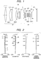
- FIG. 1 is a cross-sectional view of a lens of an optical system according to a first embodiment of the invention.
- FIG. 2 is a diagram showing aberrations when the object distance is infinite, in the first embodiment of the invention.
- FIG. 3 is a cross-sectional view of a lens of an optical system according to a second embodiment of the invention.
- FIG. 4 is a diagram showing aberrations when the object distance is infinite, in the second embodiment of the invention.
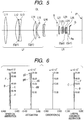
- FIG. 5 is a cross-sectional view of a lens of an optical system according to a third embodiment of the invention.
- FIG. 6 is a diagram showing aberrations when the object distance is infinite, in the third embodiment of the invention.
- OL, LF, LR, and S denote an optical system (image taking optical system), a front unit having positive refractive power, a rear unit having positive or negative refractive power, and an aperture stop, respectively.
- IP denotes an image surface that corresponds to an image taking surface of a solid-state image sensor (photoelectric conversion element), such as a CCD sensor or a CMOS sensor, when the optical system is used as an image taking optical system of a video camera or a digital still camera and corresponds to a photosensitive surface, such as a film surface, when the optical system is used as a camera for a silver halide film.
- d, g, C, and F denote a d-line, a g-line, a C-line, and an F-line, respectively.
- dS and dM denote a sagittal image surface and a meridional image surface of the d-line, respectively
- gS and gM denote a sagittal image surface and a meridional image surface of the g-line, respectively.
- Lateral chromatic aberrations are represented by the g-line, the F-line, and the C-line.
- G denotes a glass block, such as an optical filter or a faceplate. In this embodiment, it is assumed that the glass block G is not included in the rear unit LR.
- a back focus indicates the distance from a last lens surface Re of a last lens of the rear unit LR closest to the image side to the image surface IP, in a state where the glass block G does not present.
- a partial dispersion ratio and an Abbe number of a material of the lens that is used in the image taking optical system according to this embodiment are as follows. That is, when refractive indexes of Fraunhofer lines with respect to the g-line (wavelength of 435.8 nm), the F-line (wavelength of 486.1 nm), the d-line (wavelength of 587.6 nm), and the C-line (wavelength of 656.3 nm) are defined as Ng, NF, Nd, and NC, respectively; the Abbe number vd and the partial dispersion ratio ⁇ gF of the material with respect to the g-line and the F-line is represented by the following conditional equations.
- ⁇ d Nd ⁇ 1 / NF ⁇ NC
- ⁇ gF Ng ⁇ NF / NF ⁇ NC
- the optical system according to each embodiment is used in an image taking apparatus, such as a digital camera, a video camera, and a camera for a silver halide film, an observation apparatus, such as a telescope and binoculars, and an optical apparatus, such as a projector.
- an image taking apparatus such as a digital camera, a video camera, and a camera for a silver halide film
- an observation apparatus such as a telescope and binoculars
- an optical apparatus such as a projector.
- the positive refractive power of the front unit is increased to decrease the entire lens length and the effective diameter of the front lens.
- the positive refractive power is increased, it becomes difficult to obtain high optical performance, because a longitudinal chromatic aberration and a lateral chromatic aberration are greatly generated.
- a lens that is formed of a material, such as fluorite, having low dispersion and anomalous partial dispersion, is used in the front unit having the positive refractive power where both of the incident height of an on-axis ray and the incident height of an off-axis principal ray are large. That is, with such a structure, even though the positive refractive power of the front unit is increased to some degree, the longitudinal chromatic aberration and the lateral chromatic aberration are to be satisfactorily corrected. However, the increase of the positive refractive power of the front unit must be restricted to some degree in order to satisfactorily correct both of the longitudinal chromatic aberration and the lateral chromatic aberration. That is, it is tough to sufficiently increase the positive refractive power.
- a material such as fluorite, which has a low refractive index and low dispersion and anomalous partial dispersion, is used in a negative lens of a third lens unit where the incident height of an on-axis ray is small and the incident height of an off-axis principal ray is large.
- a lateral chromatic aberration of the g-line is effectively corrected.
- the negative lens that is formed of the material having the low refractive index and the low dispersion a correction effect of image surface curvature or astigmatism and lateral chromatic aberrations of the C-line and the F-line is not sufficient. For this reason, it is difficult to sufficiently increase the refractive power of the front unit.
- a negative lens Gn1 that is formed of a material having a high refractive index, high dispersion, and anomalous partial dispersion is disposed in the rear unit LR.
- a correction effect of the lateral chromatic aberration, the image surface curvature, and the astigmatism can be sufficiently obtained in the rear unit LR. Therefore, the positive refractive power of the front unit LF can be sufficiently increased and the entire lens length or the effective diameter of the front lens can be decreased.
- optical system image taking optical system
- a positive lens Gp1 formed of a material having anomalous partial dispersion as an object side lens of the front unit LF where the incident height of the on-axis ray is large, the longitudinal chromatic aberration is corrected.
- a value exceeds an upper limit of the conditional equation (1) it is difficult to obtain a material which is easy to process, and the material is restricted to a material, such as a resin material which is difficult to process. For this reason, from the viewpoint of productivity, it is difficult to stably provide superior optical performance required in the telescopic lens. If the value is below a lower limit of the conditional equation (1), the longitudinal chromatic aberrations of the C-line and the F-line are excessively generated. For this reason, it is needed to decrease the refractive power of the positive lens Gp1, which leads to the increase in the entire lens length and the effective diameter of the front lens.
- conditional equation (2) If a value exceeds an upper limit of the conditional equation (2), it is difficult to obtain a material which is easy to process, and the material is restricted to a material, such as a resin material which is difficult to process. For this reason, from the viewpoint of productivity, it is difficult to stably provide superior optical performance required in the telescopic lens. If the value is below a lower limit of the conditional equation (2), the longitudinal chromatic aberration of the g-line is insufficiently generated. For this reason, it becomes difficult to obtain a superior chromatic aberration characteristic.
- numerical ranges of the conditional equations (1) and (2) are preferably set to meet the following: 80 ⁇ ⁇ dp 1 ⁇ 97 0.025 ⁇ ⁇ gFp 1 ⁇ 0.6438 + 0.001682 ⁇ ⁇ dp 1 ⁇ 0.080
- an anomalous partial dispersion material that has a high refractive index and high dispersion is used in the negative lens of the image surface side of the rear unit where the incident height of the on-axis ray is small and the incident height of the off-axis principal ray is large.
- Ndn1 and ⁇ dn1 refractive index and an Abbe number of the material of the negative lens Gn1
- ⁇ gFn1 partial dispersion ratio of the material with respect to the g-line and the F-line
- a value exceeds than an upper limit of the conditional equation (3) it is difficult to obtain a material which is easy to process, and the material is restricted to a material, such as a resin material, which is difficult to process. For this reason, from the viewpoint of productivity, it becomes difficult to stably provide superior optical performance required in the telescopic lens. If the value is below a lower limit of the conditional equation (3), since the correction of the image surface curvature and the astigmatism is insufficient, it is needed to decrease the positive refractive power of the front unit, which may result in the increase in the entire lens length and the effective diameter of the front lens.
- a value exceeds an upper limit of the conditional equation (4) it is difficult to obtain a material which is easy to process, and the material is restricted to a material, such as a resin material, which is difficult to process. For this reason, from the viewpoint of productivity, it becomes difficult to stably provide superior optical performance required in the telescopic lens. If the value is below a lower limit of the conditional equation (4), the lateral chromatic aberration of the g-line is insufficiently generated. For this reason, it becomes difficult to obtain superior optical performance.
- conditional equations (3) and (4) may be set as represented by the following conditional equations. 1.80 ⁇ Ndn 1 ⁇ 2.00 0.023 ⁇ ⁇ gFn 1 ⁇ 0.6438 + 0.001682 ⁇ ⁇ dn 1 ⁇ 0.070
- the various aberrations including the chromatic aberration are satisfactorily corrected using the method described above, and the image taking optical system with a small size and light weight is obtained.
- preferable conditions that are needed to more effectively obtain an optical system that has a small size, light weight, and superior optical performance will be described.
- the negative lens Gn1 of the rear unit LR is disposed in a state where the distance from the aperture stop S is between 0.5 L and 1.0 L. Thereby, the lateral chromatic aberration is satisfactorily corrected.
- the disposing of the negative lens Gn1 in a state where the distance from the aperture stop is between 0.5 L and 1.0 L means that the entire negative lens Gn1 is disposed within the range of the distance.
- the incident height of the off-axis principal ray decreases. As a result, it becomes difficult to obtain a superior correction effect of the lateral chromatic aberration. Since the incident height of the on-axis ray increases and the longitudinal chromatic aberration of the g-line is excessively corrected, this is not preferable.
- the rear unit LR preferably has at least one positive lens Gp2.
- a refractive index and an Abbe number of a material of the positive lens Gp2 with respect to the d-line are defined as Ndp2 and vdp2, respectively, and the partial dispersion ratio of the material with respect to the g-line and the F-line is defined as ⁇ gFp2, at least one of the following conditional equations (5) and (6) may be satisfied. Thereby, the lateral chromatic aberration is satisfactorily corrected. 1.90 ⁇ Ndp 2 + 0.0125 ⁇ dp 2 ⁇ 2.24 ⁇ 0.010 ⁇ ⁇ gFp 2 ⁇ 0.6438 + 0.001682 ⁇ ⁇ dp 2 ⁇ 0.003
- conditional equation (5) If a value exceeds an upper limit of the conditional equation (5), the image surface curvature and the astigmatism are excessively corrected when the refractive index Ndp2 is large and correction of the lateral chromatic aberrations of the C-line and the F-line becomes insufficient when the Abbe number vdp2 is large. For this reason, it becomes difficult to obtain superior optical performance. If the value is below a lower limit of the conditional equation (5), it is difficult to obtain a material which is easy to process, and the material is restricted to a material, such as a resin material, which is difficult to process. For this reason, from the viewpoint of productivity, it becomes difficult to stably provide superior optical performance required in the telescopic lens.
- conditional equation (6) If a value exceeds an upper limit of the conditional equation (6), the lateral chromatic aberration of the g-line is excessively corrected, and the correction effect of the lateral chromatic aberration that is obtained by the negative lens Gn1 of the rear unit LR may be cancelled. If the value is below a lower limit of the conditional equation (6), it is difficult to obtain a material that satisfies the conditional equation (5), and the material is restricted to a material, such as a resin material, which is difficult to process. For this reason, from the viewpoint of productivity, it becomes difficult to stably provide superior optical performance.
- conditional equations (5) and (6) may be preferably set as represented by the following conditional equations. 2.00 ⁇ Ndp 2 + 0.0125 ⁇ dp 2 ⁇ 2.20 ⁇ 0.008 ⁇ ⁇ gFp 2 ⁇ 0.6438 + 0.001682 ⁇ ⁇ dp 2 ⁇ 0.001
- the positive lens Gp2 is disposed in a state where the distance from the aperture stop S is between 0.5 L and 1.0 L. Thereby, the lateral chromatic aberration is satisfactorily corrected.
- the positive lens Gp2 of the rear unit LR When the positive lens Gp2 of the rear unit LR is disposed at the position where the distance from the aperture stop S is shorter than 0.5 L, the incident height of the off-axis principal ray decreases. As a result, it becomes difficult to obtain a superior correction effect of the lateral chromatic aberration. Since the incident height of the on-axis ray increases and the longitudinal chromatic aberration of the g-line is insufficiently generated, this is not preferable.
- the positive lens Gp2 of the rear unit LR uses a material with a niobium oxide (Nb 2 O 3 ) as a principal substance.
- a material that satisfies the conditional equations (3) and (4) among materials currently available from the market includes a material with a neptunium oxide (NpO 2 ) as a principal substance.
- NpO 2 neptunium oxide
- transmittance of blue transmissive light is low.
- the image taking optical system needs to maintain a color tone of the transmissive light of the optical system with a proper balance to reproduce a color.
- the negative lens Gn1 that satisfies the conditional equations (3) and (4) is disposed on the image side of the rear unit LR of the optical system where the outer diameter is small and the central thickness can be easily decreased, to moderate a change in the color tone of the transmissive light, and the shift to the side of a yellow color is alleviated.
- the positive lens Gp2 of the rear unit LR that is formed of a high dispersion material may be used to make a color of the transmissive light of the entire optical system looks like a white color.
- the positive lens Gp2 of the rear unit LR that is formed of the high dispersion material has the large thickness and uses in many cases a material with titanium oxide (TiO 2 ) where transmittance of blue transmissive light is slightly low as a principal substance. For this reason, the color tone of the transmissive light may be slightly shifted to the side of a yellow color. Accordingly, with use of a material of which a principle substance is Nb 2 O 3 which does not have high dispersion as much as TiO 2 , but has relatively high transmittance of the blue transmissive light, a change in the color tone of the entire optical system is further suppressed as compared with the case of using the material of which the principal substance is TiO 2 .
- TiO 2 titanium oxide
- the front unit LF includes a biconvex positive lens L11, a biconvex positive lens (Gp1) L12 that satisfies the conditional equations (1) and (2), and a double-concave lens L13, which are provided in this order from the object side to the image side.
- the front unit LF further includes a biconvex positive lens (Gp1) L14 that satisfies the conditional equations (1) and (2), a meniscus-shaped negative lens L15, and a cemented lens L16 where a positive lens and a negative lens are bonded to each other.
- the longitudinal chromatic aberration is satisfactorily corrected by the positive lens L12 and the positive lens L14.
- the positive lens that satisfies the conditional equations (1) and (2) is preferably disposed as the lens on the object side where the incident height of the on-axis ray is largest.
- the materials satisfying the above conditional equations mainly include materials such as fluorite, which are prone to be damaged. Accordingly, the positive lens L11 of a material that is not easily damaged is disposed to be closest to the object side to protect a surface from the external damage.
- the rear unit LR includes a cemented lens L21 where a negative lens and a positive lens are bonded to each other, a positive lens L22, a cemented lens L23 where a positive lens and a negative lens are bonded to each other, a negative lens L24, and a positive lens L25.
- the rear unit LR further includes a cemented lens L26 where the positive lens Gp2 with Nb 2 O 3 satisfying the conditional equations (5) and (6) as the principal substance and the negative lens Gn1 with NpO 2 satisfying the conditional equalities 3 and 4 as the principal substance are bonded to each other.
- the lateral chromatic aberration is satisfactorily corrected by the cemented lens L26 which has the small incident height of the on-axis ray and the large incident height of the off-axis principal ray and are disposed to be closest to the image surface side, without giving a great influence to the longitudinal chromatic aberration.
- the material with Nb 2 O 3 as the principal substance is used in the positive lens Gp2 of the cemented lens L26 where the positive lens Gp2 has a relatively thick body because the transmittance of the blue transmissive light is decreased by the negative lens Gn1 of the cemented lens L26 with NpO 2 as the principal substance, so that the change in the color tone of the transmissive light in the entire optical system is suppressed.
- the cemented lens L23 and the negative lens L24 are integrally moved to have a perpendicular component with respect to the optical axis, and the vibration is absorbed.
- the front unit LF has the same configuration as that of the first numerical embodiment.
- the rear unit LR includes a cemented lens L21 where a negative lens and a positive lens are bonded to each other, a cemented lens L22 where a positive lens and a negative lens are bonded to each other, a negative lens L23, and a positive lens L24.
- the rear unit LR further includes a cemented lens L25 where the positive lens Gp2 with Nb 2 O 3 satisfying the conditional equations (5) and (6) as the principal substance and the negative lens Gn1 with NpO 2 satisfying the conditional equations (3) and (4) as the principal substance are bonded to each other.
- the cemented lens L25 has the same effect as the cemented lens L26 according to the first numerical embodiment.
- the cemented lens L22 and the negative lens L23 are integrally moved to have a perpendicular component with respect to the optical axis, and the vibration is absorbed.
- a telescopic lens that is shown in the third numerical embodiment and FIG. 5 has the same configuration as the second numerical embodiment but has a longer focal length.
- i represents order of counting from the object side.
- ri represents a curvature radius of an i-th optical surface
- di represents an on-axis interval between an i-th surface and a (i + 1)-th surface
- ndi and vdi represent a refractive index and an Abbe number of a medium between the i-th surface and the (i + 1)-th surface with respect to the d-line, respectively.
- f represents the focal length
- Fno represents an F number
- ⁇ represents a half angle of view.
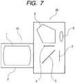
- an image taking lens 10 includes the image taking optical system 1 according to the first, second, and third numerical embodiments.
- the image taking optical system 1 is held in a lens barrel 2 corresponding to a holding member.
- a camera body 20 has a quick return mirror 3 that reflects a ray from the image taking lens 10 to the upper side and a focusing plate 4 that is disposed at an image formation position of the image taking lens 10.
- the camera body 20 further includes a pentagonal prism 5 that converts a reverse image formed on the focusing plate 4 to an erect image and an eyepiece lens 6 that enlarges the erect image and forms an enlarged image.
- a photosensitive surface 7 is provided with a solid-state image sensor (photoelectric conversion element), such as a CCD sensor or a CMOS sensor, or a silver halide film on the surface thereof.
- a solid-state image sensor photoelectric conversion element
- the quick return mirror 3 is retracted from an optical path, and an image is formed on the photosensitive surface 7 by the image taking lens 10.
- the invention can be applied to a single-lens reflex camera which does not have a quick return mirror.
- An zoom lens includes a front unit having positive refractive power, an aperture stop, and a rear unit.
- the front unit has a positive lens Gp1 and the rear unit has a negative lens Gn1.
- an Abbe number of a material of the positive lens Gp1 and a partial dispersion ratio of the material thereof for a g-line and an F-line is defined as ⁇ dp1 and ⁇ gFp1 respectively
- a refractive index and an Abbe number of a material of the negative lens Gn1 for a d-line and a partial dispersion ratio of the material thereof for the g-line and the F-line is defined as Ndn1 ⁇ dn1 and ⁇ gFn1 respectively, satisfying the following conditions: 75 ⁇ ⁇ dp1 ⁇ 99, 0.020 ⁇ ⁇ gFp1 - 0.6438 + 0.001682 x ⁇ dp1 ⁇ 0.100, 1.75 ⁇ Ndn1 ⁇ 2.10, and 0.020 ⁇ ⁇ g
Landscapes
- Physics & Mathematics (AREA)
- General Physics & Mathematics (AREA)
- Optics & Photonics (AREA)
- Lenses (AREA)
Applications Claiming Priority (1)
| Application Number | Priority Date | Filing Date | Title |
|---|---|---|---|
| JP2009239163A JP5264674B2 (ja) | 2009-10-16 | 2009-10-16 | 光学系及びそれを有する光学機器 |
Publications (2)
| Publication Number | Publication Date |
|---|---|
| EP2312372A1 EP2312372A1 (en) | 2011-04-20 |
| EP2312372B1 true EP2312372B1 (en) | 2017-01-04 |
Family
ID=43216484
Family Applications (1)
| Application Number | Title | Priority Date | Filing Date |
|---|---|---|---|
| EP10177870.2A Active EP2312372B1 (en) | 2009-10-16 | 2010-09-21 | Optical system and optical apparatus having the same |
Country Status (4)
| Country | Link |
|---|---|
| US (1) | US8000026B2 (enExample) |
| EP (1) | EP2312372B1 (enExample) |
| JP (1) | JP5264674B2 (enExample) |
| CN (1) | CN102043230B (enExample) |
Families Citing this family (17)
| Publication number | Priority date | Publication date | Assignee | Title |
|---|---|---|---|---|
| JP5904013B2 (ja) * | 2012-05-30 | 2016-04-13 | 株式会社ニコン | 撮影レンズ、光学機器、および撮影レンズの製造方法 |
| JP5904015B2 (ja) * | 2012-05-30 | 2016-04-13 | 株式会社ニコン | 撮影レンズ、光学機器、および撮影レンズの製造方法 |
| JP5949438B2 (ja) * | 2012-10-23 | 2016-07-06 | 株式会社ニコン | 光学系、これを具備する光学装置 |
| JP5841675B2 (ja) * | 2012-11-08 | 2016-01-13 | 富士フイルム株式会社 | ズームレンズおよび撮像装置 |
| CN103293636B (zh) * | 2013-02-06 | 2016-04-20 | 玉晶光电(厦门)有限公司 | 可携式电子装置与其光学成像镜头 |
| JP6151144B2 (ja) * | 2013-09-24 | 2017-06-21 | 株式会社シグマ | 結像光学系 |
| CN104076494B (zh) * | 2014-07-03 | 2016-04-27 | 福建福光股份有限公司 | 宽光谱强光力摄像镜头 |
| US9772469B2 (en) * | 2014-09-17 | 2017-09-26 | Ricoh Company, Ltd. | Image forming lens and image capturing device |
| JP6627313B2 (ja) * | 2015-08-03 | 2020-01-08 | 株式会社シグマ | 結像光学系 |
| DE102017106837B4 (de) * | 2017-03-30 | 2023-02-23 | Carl Zeiss Jena Gmbh | Linsensystem für ein Makroobjektiv für den industriellen Einsatz bei der Qualitätssicherung im Produktionsprozess, Makroobjektiv sowie System |
| JP7005312B2 (ja) | 2017-11-20 | 2022-01-21 | キヤノン株式会社 | 光学系及びそれを有する撮像装置 |
| CN111492294B (zh) * | 2017-12-19 | 2022-05-10 | 松下知识产权经营株式会社 | 投影镜头系统以及图像投影装置 |
| JP7140571B2 (ja) * | 2018-07-04 | 2022-09-21 | キヤノン株式会社 | 光学系および撮像装置 |
| WO2020217791A1 (ja) | 2019-04-26 | 2020-10-29 | 株式会社ニコン | 光学系、光学機器及び光学系の製造方法 |
| US12461350B2 (en) * | 2019-08-30 | 2025-11-04 | Nikon Corporation | Optical system, optical apparatus and method for manufacturing the optical system, and zoom optical system, optical apparatus and method for manufacturing the zoom optical system |
| JP7551384B2 (ja) * | 2020-07-31 | 2024-09-17 | キヤノン株式会社 | ズームレンズ |
| DE102021103587B4 (de) | 2021-02-16 | 2022-09-29 | Carl Zeiss Ag | Kompaktes Teleobjektiv mit Materialien mit anomaler relativer Teildispersion, Kamera sowie mobiles Gerät |
Family Cites Families (6)
| Publication number | Priority date | Publication date | Assignee | Title |
|---|---|---|---|---|
| US6115188A (en) * | 1997-10-16 | 2000-09-05 | Canon Kabushiki Kaisha | Optical system and optical apparatus having the same |
| JP4032502B2 (ja) * | 1998-05-14 | 2008-01-16 | 株式会社ニコン | 大口径比内焦超望遠レンズ |
| US7715108B2 (en) * | 2005-09-13 | 2010-05-11 | Olympus Corporation | Image forming optical system and electronic image pickup apparatus using image forming optical system |
| JP4829590B2 (ja) * | 2005-10-25 | 2011-12-07 | キヤノン株式会社 | 撮影光学系及びそれを有する撮像装置 |
| JP4898379B2 (ja) * | 2006-10-11 | 2012-03-14 | キヤノン株式会社 | 撮影光学系及びそれを有する撮像装置 |
| JP4898408B2 (ja) * | 2006-12-07 | 2012-03-14 | キヤノン株式会社 | 光学系及びそれを有する撮像装置 |
-
2009
- 2009-10-16 JP JP2009239163A patent/JP5264674B2/ja active Active
-
2010
- 2010-09-21 EP EP10177870.2A patent/EP2312372B1/en active Active
- 2010-10-12 CN CN2010105034701A patent/CN102043230B/zh active Active
- 2010-10-14 US US12/904,727 patent/US8000026B2/en active Active
Non-Patent Citations (1)
| Title |
|---|
| None * |
Also Published As
| Publication number | Publication date |
|---|---|
| US20110090576A1 (en) | 2011-04-21 |
| JP2011085788A (ja) | 2011-04-28 |
| EP2312372A1 (en) | 2011-04-20 |
| US8000026B2 (en) | 2011-08-16 |
| CN102043230B (zh) | 2012-07-04 |
| CN102043230A (zh) | 2011-05-04 |
| JP5264674B2 (ja) | 2013-08-14 |
Similar Documents
| Publication | Publication Date | Title |
|---|---|---|
| EP2312372B1 (en) | Optical system and optical apparatus having the same | |
| EP2312341B1 (en) | Rear attachment lens and imaging optical system including the same | |
| EP2090916B1 (en) | Retrofocus objective using lenses exhibiting relative partial dispersion | |
| EP2149808B1 (en) | Retrofocus type of imaging lens | |
| US8223439B2 (en) | Optical system and image pickup apparatus having the optical system | |
| JP5028104B2 (ja) | ズームレンズ及びそれを有する撮像装置 | |
| EP2309308A1 (en) | Optical system and optical device including the same | |
| JP5493308B2 (ja) | ズームレンズ系、及び、このズームレンズ系を備えた光学機器 | |
| US9128273B2 (en) | Zoom lens and image pickup apparatus equipped with zoom lens | |
| US20120300113A1 (en) | Zoom lens and image pickup apparatus equipped with zoom lens | |
| JP2015141384A (ja) | 撮像レンズおよび撮像装置 | |
| US8248703B2 (en) | Zoom lens and optical apparatus having the zoom lens | |
| EP4036627A1 (en) | Zoom lens and image pickup apparatus having the same | |
| JP2010044226A (ja) | ズームレンズ系、このズームレンズ系を備えた光学機器、及び、ズームレンズ系を用いた変倍方法 | |
| US20250291160A1 (en) | Optical system and imaging apparatus including the same | |
| US20120229915A1 (en) | Zoom lens and image pickup apparatus having the same | |
| KR101708895B1 (ko) | 텔레포토 단초점 렌즈계 및 이를 포함한 촬영 장치 | |
| CN105190393A (zh) | 广角透镜及摄像装置 | |
| CN104145200A (zh) | 光学系统、光学装置和制造光学系统的方法 | |
| US9405094B2 (en) | Photographing lens, optical apparatus and method for manufacturing the photographing lens | |
| JP5682715B2 (ja) | ズームレンズ系、及び、このズームレンズ系を備えた光学機器 | |
| JP4859178B2 (ja) | 2群ズームレンズ及びそれを有する交換レンズ及びそれを有する電子撮像装置 | |
| US7542215B2 (en) | Zoom lens system and optical apparatus using the same | |
| JP5868186B2 (ja) | ズームレンズ及びそれを有する撮像装置 | |
| JP6354222B2 (ja) | ズームレンズ、光学装置 |
Legal Events
| Date | Code | Title | Description |
|---|---|---|---|
| PUAI | Public reference made under article 153(3) epc to a published international application that has entered the european phase |
Free format text: ORIGINAL CODE: 0009012 |
|
| AK | Designated contracting states |
Kind code of ref document: A1 Designated state(s): AL AT BE BG CH CY CZ DE DK EE ES FI FR GB GR HR HU IE IS IT LI LT LU LV MC MK MT NL NO PL PT RO SE SI SK SM TR |
|
| AX | Request for extension of the european patent |
Extension state: BA ME RS |
|
| 17P | Request for examination filed |
Effective date: 20111020 |
|
| GRAP | Despatch of communication of intention to grant a patent |
Free format text: ORIGINAL CODE: EPIDOSNIGR1 |
|
| INTG | Intention to grant announced |
Effective date: 20160719 |
|
| RIN1 | Information on inventor provided before grant (corrected) |
Inventor name: SUGITA, SHIGENOBU |
|
| GRAS | Grant fee paid |
Free format text: ORIGINAL CODE: EPIDOSNIGR3 |
|
| GRAA | (expected) grant |
Free format text: ORIGINAL CODE: 0009210 |
|
| AK | Designated contracting states |
Kind code of ref document: B1 Designated state(s): AL AT BE BG CH CY CZ DE DK EE ES FI FR GB GR HR HU IE IS IT LI LT LU LV MC MK MT NL NO PL PT RO SE SI SK SM TR |
|
| REG | Reference to a national code |
Ref country code: GB Ref legal event code: FG4D |
|
| REG | Reference to a national code |
Ref country code: CH Ref legal event code: EP |
|
| REG | Reference to a national code |
Ref country code: AT Ref legal event code: REF Ref document number: 859799 Country of ref document: AT Kind code of ref document: T Effective date: 20170115 |
|
| REG | Reference to a national code |
Ref country code: FR Ref legal event code: PLFP Year of fee payment: 8 |
|
| REG | Reference to a national code |
Ref country code: IE Ref legal event code: FG4D |
|
| REG | Reference to a national code |
Ref country code: DE Ref legal event code: R096 Ref document number: 602010039280 Country of ref document: DE |
|
| REG | Reference to a national code |
Ref country code: LT Ref legal event code: MG4D Ref country code: NL Ref legal event code: MP Effective date: 20170104 |
|
| REG | Reference to a national code |
Ref country code: AT Ref legal event code: MK05 Ref document number: 859799 Country of ref document: AT Kind code of ref document: T Effective date: 20170104 |
|
| PG25 | Lapsed in a contracting state [announced via postgrant information from national office to epo] |
Ref country code: NL Free format text: LAPSE BECAUSE OF FAILURE TO SUBMIT A TRANSLATION OF THE DESCRIPTION OR TO PAY THE FEE WITHIN THE PRESCRIBED TIME-LIMIT Effective date: 20170104 |
|
| PG25 | Lapsed in a contracting state [announced via postgrant information from national office to epo] |
Ref country code: LT Free format text: LAPSE BECAUSE OF FAILURE TO SUBMIT A TRANSLATION OF THE DESCRIPTION OR TO PAY THE FEE WITHIN THE PRESCRIBED TIME-LIMIT Effective date: 20170104 Ref country code: HR Free format text: LAPSE BECAUSE OF FAILURE TO SUBMIT A TRANSLATION OF THE DESCRIPTION OR TO PAY THE FEE WITHIN THE PRESCRIBED TIME-LIMIT Effective date: 20170104 Ref country code: IS Free format text: LAPSE BECAUSE OF FAILURE TO SUBMIT A TRANSLATION OF THE DESCRIPTION OR TO PAY THE FEE WITHIN THE PRESCRIBED TIME-LIMIT Effective date: 20170504 Ref country code: GR Free format text: LAPSE BECAUSE OF FAILURE TO SUBMIT A TRANSLATION OF THE DESCRIPTION OR TO PAY THE FEE WITHIN THE PRESCRIBED TIME-LIMIT Effective date: 20170405 Ref country code: FI Free format text: LAPSE BECAUSE OF FAILURE TO SUBMIT A TRANSLATION OF THE DESCRIPTION OR TO PAY THE FEE WITHIN THE PRESCRIBED TIME-LIMIT Effective date: 20170104 Ref country code: NO Free format text: LAPSE BECAUSE OF FAILURE TO SUBMIT A TRANSLATION OF THE DESCRIPTION OR TO PAY THE FEE WITHIN THE PRESCRIBED TIME-LIMIT Effective date: 20170404 |
|
| PG25 | Lapsed in a contracting state [announced via postgrant information from national office to epo] |
Ref country code: ES Free format text: LAPSE BECAUSE OF FAILURE TO SUBMIT A TRANSLATION OF THE DESCRIPTION OR TO PAY THE FEE WITHIN THE PRESCRIBED TIME-LIMIT Effective date: 20170104 Ref country code: PL Free format text: LAPSE BECAUSE OF FAILURE TO SUBMIT A TRANSLATION OF THE DESCRIPTION OR TO PAY THE FEE WITHIN THE PRESCRIBED TIME-LIMIT Effective date: 20170104 Ref country code: BG Free format text: LAPSE BECAUSE OF FAILURE TO SUBMIT A TRANSLATION OF THE DESCRIPTION OR TO PAY THE FEE WITHIN THE PRESCRIBED TIME-LIMIT Effective date: 20170404 Ref country code: LV Free format text: LAPSE BECAUSE OF FAILURE TO SUBMIT A TRANSLATION OF THE DESCRIPTION OR TO PAY THE FEE WITHIN THE PRESCRIBED TIME-LIMIT Effective date: 20170104 Ref country code: SE Free format text: LAPSE BECAUSE OF FAILURE TO SUBMIT A TRANSLATION OF THE DESCRIPTION OR TO PAY THE FEE WITHIN THE PRESCRIBED TIME-LIMIT Effective date: 20170104 Ref country code: PT Free format text: LAPSE BECAUSE OF FAILURE TO SUBMIT A TRANSLATION OF THE DESCRIPTION OR TO PAY THE FEE WITHIN THE PRESCRIBED TIME-LIMIT Effective date: 20170504 Ref country code: AT Free format text: LAPSE BECAUSE OF FAILURE TO SUBMIT A TRANSLATION OF THE DESCRIPTION OR TO PAY THE FEE WITHIN THE PRESCRIBED TIME-LIMIT Effective date: 20170104 |
|
| REG | Reference to a national code |
Ref country code: DE Ref legal event code: R097 Ref document number: 602010039280 Country of ref document: DE |
|
| PG25 | Lapsed in a contracting state [announced via postgrant information from national office to epo] |
Ref country code: IT Free format text: LAPSE BECAUSE OF FAILURE TO SUBMIT A TRANSLATION OF THE DESCRIPTION OR TO PAY THE FEE WITHIN THE PRESCRIBED TIME-LIMIT Effective date: 20170104 Ref country code: RO Free format text: LAPSE BECAUSE OF FAILURE TO SUBMIT A TRANSLATION OF THE DESCRIPTION OR TO PAY THE FEE WITHIN THE PRESCRIBED TIME-LIMIT Effective date: 20170104 Ref country code: CZ Free format text: LAPSE BECAUSE OF FAILURE TO SUBMIT A TRANSLATION OF THE DESCRIPTION OR TO PAY THE FEE WITHIN THE PRESCRIBED TIME-LIMIT Effective date: 20170104 Ref country code: EE Free format text: LAPSE BECAUSE OF FAILURE TO SUBMIT A TRANSLATION OF THE DESCRIPTION OR TO PAY THE FEE WITHIN THE PRESCRIBED TIME-LIMIT Effective date: 20170104 Ref country code: SK Free format text: LAPSE BECAUSE OF FAILURE TO SUBMIT A TRANSLATION OF THE DESCRIPTION OR TO PAY THE FEE WITHIN THE PRESCRIBED TIME-LIMIT Effective date: 20170104 |
|
| PLBE | No opposition filed within time limit |
Free format text: ORIGINAL CODE: 0009261 |
|
| STAA | Information on the status of an ep patent application or granted ep patent |
Free format text: STATUS: NO OPPOSITION FILED WITHIN TIME LIMIT |
|
| PG25 | Lapsed in a contracting state [announced via postgrant information from national office to epo] |
Ref country code: SM Free format text: LAPSE BECAUSE OF FAILURE TO SUBMIT A TRANSLATION OF THE DESCRIPTION OR TO PAY THE FEE WITHIN THE PRESCRIBED TIME-LIMIT Effective date: 20170104 Ref country code: DK Free format text: LAPSE BECAUSE OF FAILURE TO SUBMIT A TRANSLATION OF THE DESCRIPTION OR TO PAY THE FEE WITHIN THE PRESCRIBED TIME-LIMIT Effective date: 20170104 |
|
| 26N | No opposition filed |
Effective date: 20171005 |
|
| PG25 | Lapsed in a contracting state [announced via postgrant information from national office to epo] |
Ref country code: SI Free format text: LAPSE BECAUSE OF FAILURE TO SUBMIT A TRANSLATION OF THE DESCRIPTION OR TO PAY THE FEE WITHIN THE PRESCRIBED TIME-LIMIT Effective date: 20170104 |
|
| REG | Reference to a national code |
Ref country code: CH Ref legal event code: PL |
|
| PG25 | Lapsed in a contracting state [announced via postgrant information from national office to epo] |
Ref country code: MC Free format text: LAPSE BECAUSE OF FAILURE TO SUBMIT A TRANSLATION OF THE DESCRIPTION OR TO PAY THE FEE WITHIN THE PRESCRIBED TIME-LIMIT Effective date: 20170104 |
|
| REG | Reference to a national code |
Ref country code: IE Ref legal event code: MM4A |
|
| REG | Reference to a national code |
Ref country code: BE Ref legal event code: MM Effective date: 20170930 |
|
| PG25 | Lapsed in a contracting state [announced via postgrant information from national office to epo] |
Ref country code: LU Free format text: LAPSE BECAUSE OF NON-PAYMENT OF DUE FEES Effective date: 20170921 |
|
| PG25 | Lapsed in a contracting state [announced via postgrant information from national office to epo] |
Ref country code: IE Free format text: LAPSE BECAUSE OF NON-PAYMENT OF DUE FEES Effective date: 20170921 Ref country code: LI Free format text: LAPSE BECAUSE OF NON-PAYMENT OF DUE FEES Effective date: 20170930 Ref country code: CH Free format text: LAPSE BECAUSE OF NON-PAYMENT OF DUE FEES Effective date: 20170930 |
|
| PG25 | Lapsed in a contracting state [announced via postgrant information from national office to epo] |
Ref country code: BE Free format text: LAPSE BECAUSE OF NON-PAYMENT OF DUE FEES Effective date: 20170930 |
|
| PG25 | Lapsed in a contracting state [announced via postgrant information from national office to epo] |
Ref country code: MT Free format text: LAPSE BECAUSE OF NON-PAYMENT OF DUE FEES Effective date: 20170921 |
|
| REG | Reference to a national code |
Ref country code: FR Ref legal event code: PLFP Year of fee payment: 9 |
|
| PG25 | Lapsed in a contracting state [announced via postgrant information from national office to epo] |
Ref country code: HU Free format text: LAPSE BECAUSE OF FAILURE TO SUBMIT A TRANSLATION OF THE DESCRIPTION OR TO PAY THE FEE WITHIN THE PRESCRIBED TIME-LIMIT; INVALID AB INITIO Effective date: 20100921 |
|
| PG25 | Lapsed in a contracting state [announced via postgrant information from national office to epo] |
Ref country code: CY Free format text: LAPSE BECAUSE OF NON-PAYMENT OF DUE FEES Effective date: 20170104 |
|
| PG25 | Lapsed in a contracting state [announced via postgrant information from national office to epo] |
Ref country code: MK Free format text: LAPSE BECAUSE OF FAILURE TO SUBMIT A TRANSLATION OF THE DESCRIPTION OR TO PAY THE FEE WITHIN THE PRESCRIBED TIME-LIMIT Effective date: 20170104 |
|
| PG25 | Lapsed in a contracting state [announced via postgrant information from national office to epo] |
Ref country code: TR Free format text: LAPSE BECAUSE OF FAILURE TO SUBMIT A TRANSLATION OF THE DESCRIPTION OR TO PAY THE FEE WITHIN THE PRESCRIBED TIME-LIMIT Effective date: 20170104 |
|
| PG25 | Lapsed in a contracting state [announced via postgrant information from national office to epo] |
Ref country code: AL Free format text: LAPSE BECAUSE OF FAILURE TO SUBMIT A TRANSLATION OF THE DESCRIPTION OR TO PAY THE FEE WITHIN THE PRESCRIBED TIME-LIMIT Effective date: 20170104 |
|
| PGFP | Annual fee paid to national office [announced via postgrant information from national office to epo] |
Ref country code: DE Payment date: 20250820 Year of fee payment: 16 |
|
| PGFP | Annual fee paid to national office [announced via postgrant information from national office to epo] |
Ref country code: GB Payment date: 20250820 Year of fee payment: 16 |
|
| PGFP | Annual fee paid to national office [announced via postgrant information from national office to epo] |
Ref country code: FR Payment date: 20250821 Year of fee payment: 16 |