US6115188A - Optical system and optical apparatus having the same - Google Patents
Optical system and optical apparatus having the same Download PDFInfo
- Publication number
- US6115188A US6115188A US09/172,164 US17216498A US6115188A US 6115188 A US6115188 A US 6115188A US 17216498 A US17216498 A US 17216498A US 6115188 A US6115188 A US 6115188A
- Authority
- US
- United States
- Prior art keywords
- lens
- subunit
- optical system
- lens unit
- positive
- Prior art date
- Legal status (The legal status is an assumption and is not a legal conclusion. Google has not performed a legal analysis and makes no representation as to the accuracy of the status listed.)
- Expired - Lifetime
Links
- 230000003287 optical effect Effects 0.000 title claims abstract description 155
- 230000000694 effects Effects 0.000 claims abstract description 13
- 239000000463 material Substances 0.000 claims description 13
- 230000005499 meniscus Effects 0.000 claims description 9
- 230000004075 alteration Effects 0.000 description 129
- 230000000087 stabilizing effect Effects 0.000 description 21
- 238000006073 displacement reaction Methods 0.000 description 16
- 230000007246 mechanism Effects 0.000 description 11
- 238000000034 method Methods 0.000 description 8
- 230000035945 sensitivity Effects 0.000 description 8
- 230000008859 change Effects 0.000 description 6
- 238000000926 separation method Methods 0.000 description 6
- 230000008901 benefit Effects 0.000 description 5
- 239000011521 glass Substances 0.000 description 5
- 206010010071 Coma Diseases 0.000 description 4
- 230000008602 contraction Effects 0.000 description 3
- 230000007423 decrease Effects 0.000 description 3
- 238000010586 diagram Methods 0.000 description 3
- 239000005357 flat glass Substances 0.000 description 3
- 238000005286 illumination Methods 0.000 description 3
- 230000009467 reduction Effects 0.000 description 3
- 230000009471 action Effects 0.000 description 2
- 201000009310 astigmatism Diseases 0.000 description 2
- 230000003247 decreasing effect Effects 0.000 description 2
- 230000002542 deteriorative effect Effects 0.000 description 2
- 230000011514 reflex Effects 0.000 description 2
- 238000002834 transmittance Methods 0.000 description 2
- 239000000470 constituent Substances 0.000 description 1
- 230000002349 favourable effect Effects 0.000 description 1
- 230000005484 gravity Effects 0.000 description 1
- 238000003384 imaging method Methods 0.000 description 1
- 238000012423 maintenance Methods 0.000 description 1
- 238000004519 manufacturing process Methods 0.000 description 1
- 239000000203 mixture Substances 0.000 description 1
- 230000006641 stabilisation Effects 0.000 description 1
- 238000011105 stabilization Methods 0.000 description 1
- 230000001502 supplementing effect Effects 0.000 description 1
Images
Classifications
-
- G—PHYSICS
- G02—OPTICS
- G02B—OPTICAL ELEMENTS, SYSTEMS OR APPARATUS
- G02B15/00—Optical objectives with means for varying the magnification
- G02B15/14—Optical objectives with means for varying the magnification by axial movement of one or more lenses or groups of lenses relative to the image plane for continuously varying the equivalent focal length of the objective
- G02B15/143—Optical objectives with means for varying the magnification by axial movement of one or more lenses or groups of lenses relative to the image plane for continuously varying the equivalent focal length of the objective having three groups only
- G02B15/1431—Optical objectives with means for varying the magnification by axial movement of one or more lenses or groups of lenses relative to the image plane for continuously varying the equivalent focal length of the objective having three groups only the first group being positive
- G02B15/143105—Optical objectives with means for varying the magnification by axial movement of one or more lenses or groups of lenses relative to the image plane for continuously varying the equivalent focal length of the objective having three groups only the first group being positive arranged +-+
Definitions
- the present invention relates to optical systems of the inner focus type suited to cameras for film, video cameras, video still cameras or the like.
- lens type suited to the optical systems of long focal lengths, comprising, in order from an object side, a first lens unit of positive refractive power and a second lens unit of negative refractive power, or the so-called "telephoto" type.
- This lens type is advantageous at removing, in particular, spherical aberration and securing a fast F-number.
- Japanese Laid-Open Patent Application No. Sho 55-147606 (U.S. Pat. No. 4,348,084) discloses a telephoto lens of the inner focus type having a focal length of 300 mm with an F-number of 2.8
- each of Japanese Laid-Open Patent Applications No. Sho 59-65820 and No. Sho 59-65821 discloses another telephoto lens of the inner focus type having a focal length of 135 mm with an F-number of 2.8.
- the telephoto lenses of the inner focus type proposed in the above applications each comprise, in order from an object side, a first lens unit of positive refractive power, a second lens unit of negative refractive power and a third lens unit of positive refractive power, totaling three lens units, wherein the second lens unit is made axially movable for focusing.
- the image pickup element is given a larger effective area than the necessary image frame and the image shake is electrically compensated for.
- Such an electric compensation method is widely employed in the video cameras.
- the F-number of the optical system is defined by
- D the diameter of an effective light beam coming from an object point at infinity on the optical axis.
- the large-relative-aperture telephoto lens gets a large diameter for the equivalent F-number in direct proportion to the focal length.
- the weight of the optical system increases rapidly. So, this tendency has been seen as problematic.
- the hand-held shooting gives the photographer a heavy burden, becoming a cause of the image shake and an obstacle to the long-time shooting.
- the method of compensating for the shake of the image by decentering a certain movable lens unit of the optical system so as to displace the image position is amenable to the techniques of minimizing the size of the apparatus by selecting a suitable one of the lens units for the movable lens unit.
- the inner focus type because of its using a lens unit of small size and light weight as the focusing lens, has merits that the management is easy, that a fast speed operation becomes possible, and that the holding is easy to keep, because the center of gravity of the whole lens system little changes between when focused on an infinitely distant object and when focused on an object at the minimum distance.
- the use of the inner focus type in the telephoto lens of fast F-number increases the range of variation of aberrations with focusing. This variation of aberrations, because of being difficult to correct well, comes to a cause of lowering the optical performance.
- the present invention is concerned with the image stabilizing function in the optical system which makes one lens unit movable to decenter in directions perpendicular to an optical axis.
- an object of the invention is to provide an optical system which can manifest the image stabilizing function, while still permitting the decentering aberrations to be as far suppressed as possible.
- the present invention is concerned also with the inner focus type.
- Another object of the invention is, therefore, to provide an optical system which suppresses the variation with focusing of aberrations as far as possible over a wide range of object distances.
- an optical system which comprises, in order from an object side, a first lens unit of positive refractive power, a second lens unit of negative refractive power, the second lens unit being movable along an optical axis to effect focusing, and a third lens unit of positive refractive power, the third lens unit including, in order from the object side, a first lens subunit of positive refractive power, a second lens subunit of negative refractive power and a third lens subunit of positive refractive power, wherein the second lens subunit is movable in directions perpendicular to the optical axis to displace an image formed by the optical system.
- an optical system which comprises, in order from an object side, a first lens unit of positive refractive power, the first lens unit consisting of, with boundaries formed by the widest and the second-widest spaces thereof, in order from the object side, a front lens subunit of positive refractive power, a middle lens subunit of negative refractive power and a rear lens subunit of positive refractive power, and a second lens unit of negative refractive power, the second lens unit being movable along an optical axis to effect focusing, wherein, letting a focal length of the entire optical system be denoted by f, a focal length of the front lens subunit be denoted by f1a, and a space between the front lens subunit and the rear lens subunit be denoted by D1ab, the following conditions are satisfied:
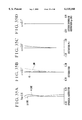
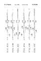
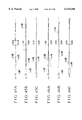
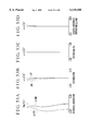
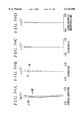
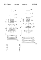
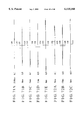
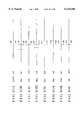
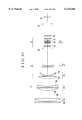
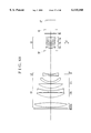
- FIG. 1 is a longitudinal section view of a numerical example 1 of the lens.
- FIG. 2 is a longitudinal section view of a numerical example 2 of the lens.
- FIG. 3 is a longitudinal section view of a numerical example 3 of the lens.
- FIG. 4 is a longitudinal section view of a numerical example 4 of the lens.
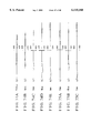
- FIG. 5 is a longitudinal section view of a numerical example 5 of the lens.
- FIG. 6 is a longitudinal section view of a numerical example 6 of the lens.
- FIG. 7 is a longitudinal section view of a numerical example 7 of the lens.
- FIG. 8 is a longitudinal section view of a numerical example 8 of the lens.
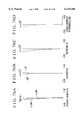
- FIG. 9 is a longitudinal section view of a numerical example 9 of the lens.
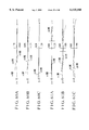
- FIG. 10 is a longitudinal section view of a numerical example 10 of the lens.
- FIG. 11 is a longitudinal section view of a numerical example 11 of the lens.
- FIG. 12 is a longitudinal section view of a numerical example 12 of the lens.
- FIG. 13 is a longitudinal section view of a numerical example 13 of the lens.
- FIG. 14 is a longitudinal section view of a numerical example 14 of the lens.
- FIG. 15 is a longitudinal section view of a numerical example 15 of the lens.
- FIG. 16 is a longitudinal section view of a numerical example 16 of the lens.
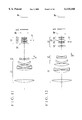
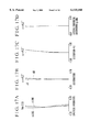
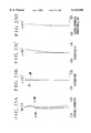
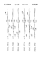
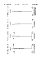
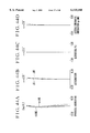
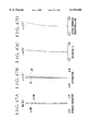
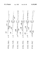
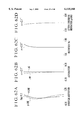
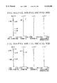
- FIGS. 17A to 17D are graphic representations of the longitudinal aberrations of the numerical example 1 in the normal state (with the image position unchanged).
- FIGS. 18A to 18C are graphic representations of the lateral aberrations of the numerical example 1 in the normal state (with the image position unchanged).
- FIGS. 19A to 19C are graphic representations of the lateral aberrations of the numerical example 1 when the image of an infinitely distant object has displaced to a corresponding position to 0.3° in image angle.
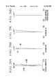
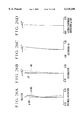
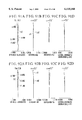
- FIGS. 20A to 20D are graphic representations of the longitudinal aberrations of the numerical example 2 in the normal state (with the image position unchanged).
- FIGS. 21A to 21C are graphic representations of the lateral aberrations of the numerical example 2 in the normal state (with the image position unchanged).
- FIGS. 22A to 22C are graphic representations of the lateral aberrations of the numerical example 2 when the image of an infinitely distant object has displaced to a corresponding position to 0.3° in image angle.
- FIGS. 23A to 23D are graphic representations of the longitudinal aberrations of the numerical example 3 in the normal state (with the image position unchanged).
- FIGS. 24A to 24C are graphic representations of the lateral aberrations of the numerical example 3 in the normal state (with the image position unchanged).
- FIGS. 25A to 25C are graphic representations of the lateral aberrations of the numerical example 3 when the image of an infinitely distant object has displaced to a corresponding position to 0.3° in image angle.
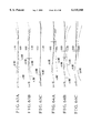
- FIGS. 26A to 26D are graphic representations of the longitudinal aberrations of the numerical example 4 in the normal state (with the image position unchanged).
- FIGS. 27A to 27C are graphic representations of the lateral aberrations of the numerical example 4 in the normal state (with the image position unchanged).
- FIGS. 28A to 28C are graphic representations of the lateral aberrations of the numerical example 4 when the image of an infinitely distant object has displaced to a corresponding position to 0.3° in image angle.
- FIGS. 29A to 29D are graphic representations of the longitudinal aberrations of the numerical example 5 in the normal state (with the image position unchanged).
- FIGS. 30A to 30C are graphic representations of the lateral aberrations of the numerical example 5 in the normal state (with the image position unchanged).
- FIGS. 31A to 31C are graphic representations of the lateral aberrations of the numerical example 5 when the image of an infinitely distant object has displaced to a corresponding position to 0.3° in image angle.
- FIGS. 32A to 32D are graphic representations of the longitudinal aberrations of the numerical example 6 in the normal state (with the image position unchanged).
- FIGS. 33A to 33C are graphic representations of the lateral aberrations of the numerical example 6 in the normal state (with the image position unchanged).
- FIGS. 34A to 34C are graphic representations of the lateral aberrations of the numerical example 6 when the image of an infinitely distant object has displaced to a corresponding position to 0.3° in image angle.
- FIGS. 35A to 35D are graphic representations of the longitudinal aberrations of the numerical example 7 in the normal state (with the image position unchanged).
- FIGS. 36A to 36C are graphic representations of the lateral aberrations of the numerical example 7 in the normal state (with the image position unchanged).
- FIGS. 37A to 37C are graphic representations of the lateral aberrations of the numerical example 7 when the image of an infinitely distant object has displaced to a corresponding position to 0.3° in image angle.
- FIGS. 38A to 38D are graphic representations of the longitudinal aberrations of the numerical example 8 in the normal state (with the image position unchanged).
- FIGS. 39A to 39C are graphic representations of the lateral aberrations of the numerical example 8 in the normal state (with the image position unchanged).
- FIGS. 40A to 40C are graphic representations of the lateral aberrations of the numerical example 8 when the image of an infinitely distant object has displaced to a corresponding position to 0.3° in image angle.
- FIGS. 41A to 41D are graphic representations of the longitudinal aberrations of the numerical example 9 in the normal state (with the image position unchanged).
- FIGS. 42A to 42C are graphic representations of the lateral aberrations of the numerical example 9 in the normal state (with the image position unchanged).
- FIGS. 43A to 43C are graphic representations of the lateral aberrations of the numerical example 9 when the image of an infinitely distant object has displaced to a corresponding position to 0.3° in image angle.
- FIGS. 44A to 44D are graphic representations of the longitudinal aberrations of the numerical example 10 in the normal state (with the image position unchanged).
- FIGS. 45A to 45C are graphic representations of the lateral aberrations of the numerical example 10 in the normal state (with the image position unchanged).
- FIGS. 46A to 46C are graphic representations of the lateral aberrations of the numerical example 10 when the image of an infinitely distant object has displaced to a corresponding position to 0.3° in image angle.
- FIGS. 47A to 47D are graphic representations of the longitudinal aberrations of the numerical example 11 in the normal state (with the image position unchanged).
- FIGS. 48A to 48C are graphic representations of the lateral aberrations of the numerical example 11 in the normal state (with the image position unchanged).
- FIGS. 49A to 49C are graphic representations of the lateral aberrations of the numerical example 11 when the image of an infinitely distant object has displaced to a corresponding position to 0.3° in image angle.
- FIGS. 50A to 50D are graphic representations of the longitudinal aberrations of the numerical example 12 in the normal state (with the image position unchanged).
- FIGS. 51A to 51C are graphic representations of the lateral aberrations of the numerical example 12 in the normal state (with the image position unchanged).
- FIGS. 52A to 52C are graphic representations of the lateral aberrations of the numerical example 12 when the image of an infinitely distant object has displaced to a corresponding position to 0.3° in image angle.
- FIGS. 53A to 53D are graphic representations of the longitudinal aberrations of the numerical example 13 in the normal state (with the image position unchanged).
- FIGS. 54A to 54C are graphic representations of the lateral aberrations of the numerical example 13 in the normal state (with the image position unchanged).
- FIGS. 55A to 55C are graphic representations of the lateral aberrations of the numerical example 13 when the image of an infinitely distant object has displaced to a corresponding position to 0.3° in image angle.
- FIGS. 56A to 56D are graphic representations of the longitudinal aberrations of the numerical example 14 in the normal state (with the image position unchanged).
- FIGS. 57A to 57C are graphic representations of the lateral aberrations of the numerical example 14 in the normal state (with the image position unchanged).
- FIGS. 58A to 58C are graphic representations of the lateral aberrations of the numerical example 14 when the image of an infinitely distant object has displaced to a corresponding position to 0.3° in image angle.
- FIGS. 59A to 59D are graphic representations of the longitudinal aberrations of the numerical example 15 in the normal state (with the image position unchanged).
- FIGS. 60A to 60C are graphic representations of the lateral aberrations of the numerical example 15 in the normal state (with the image position unchanged).
- FIGS. 61A to 61C are graphic representations of the lateral aberrations of the numerical example 15 when the image of an infinitely distant object has displaced to a corresponding position to 0.3° in image angle.
- FIGS. 62A to 62D are graphic representations of the longitudinal aberrations of the numerical example 16 in the normal state (with the image position unchanged).
- FIGS. 63A to 63C are graphic representations of the lateral aberrations of the numerical example 16 in the normal state (with the image position unchanged).
- FIGS. 64A to 64C are graphic representations of the lateral aberrations of the numerical example 16 when the image of an infinitely distant object has displaced to a corresponding position to 0.3° in image angle.
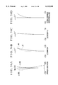
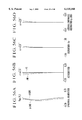
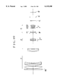
- FIG. 65 is a longitudinal section view of a numerical example 17 of the lens.
- FIG. 66 is a longitudinal section view of a numerical example 18 of the lens.
- FIG. 67 is a longitudinal section view of a numerical example 19 of the lens.
- FIG. 68 is a longitudinal section view of a numerical example 20 of the lens.
- FIG. 69 is a longitudinal section view of a numerical example 21 of the lens.
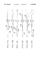
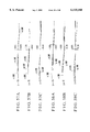
- FIGS. 70A to 70D are graphic representations of the longitudinal aberrations of the numerical example 17 in the normal state (with the image position unchanged).
- FIGS. 71A to 71E are graphic representations of the lateral aberrations of the numerical example 17 in the normal state (with the image position unchanged).
- FIGS. 72A to 72C are graphic representations of the lateral aberrations of the numerical example 17 when the image of an infinitely distant object has displaced to a corresponding position to 0.5° in image angle.
- FIGS. 73A to 73D are graphic representations of the longitudinal aberrations of the numerical example 18 in the normal state (with the image position unchanged).
- FIGS. 74A to 74E are graphic representations of the lateral aberrations of the numerical example 18 in the normal state (with the image position unchanged).
- FIGS. 75A to 75C are graphic representations of the lateral aberrations of the numerical example 18 when the image of an infinitely distant object has displaced to a corresponding position to 0.5° in image angle.
- FIGS. 76A to 76D are graphic representations of the longitudinal aberrations of the numerical example 19 in the normal state (with the image position unchanged).
- FIGS. 77A to 77E are graphic representations of the lateral aberrations of the numerical example 19 in the normal state (with the image position unchanged).
- FIGS. 78A to 78C are graphic representations of the lateral aberrations of the numerical example 19 when the image of an infinitely distant object has displaced to a corresponding position to 0.5° in image angle.
- FIGS. 79A to 79D are graphic representations of the longitudinal aberrations of the numerical example 20 in the normal state (with the image position unchanged).
- FIGS. 80A to 80E are graphic representations of the lateral aberrations of the numerical example 20 in the normal state (with the image position unchanged).
- FIGS. 81A to 81C are graphic representations of the lateral aberrations of the numerical example 20 when the image of an infinitely distant object has displaced to a corresponding position to 0.5° in image angle.
- FIGS. 82A to 82D are graphic representations of the longitudinal aberrations of the numerical example 21 in the normal state (with the image position unchanged).
- FIGS. 83A to 83E are graphic representations of the lateral aberrations of the numerical example 21 in the normal state (with the image position unchanged).
- FIGS. 84A to 84C are graphic representations of the lateral aberrations of the numerical example 21 when the image of an infinitely distant object has displaced to a corresponding position to 0.5° in image angle.
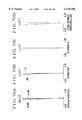
- FIG. 85 is a longitudinal section view of a numerical example 22 of the lens.
- FIG. 86 is a longitudinal section view of a numerical example 23 of the lens.
- FIG. 87 is a longitudinal section view of a numerical example 24 of the lens.
- FIG. 88 is a longitudinal section view of a numerical example 25 of the lens.
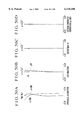
- FIGS. 89A to 89D are graphic representations of the various aberrations of the numerical example 22.
- FIGS. 90A to 90D are graphic representations of the various aberrations of the numerical example 23.
- FIGS. 91A to 91D are graphic representations of the various aberrations of the numerical example 24.
- FIGS. 92A to 92D are graphic representations of the various aberrations of the numerical example 25.
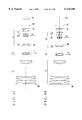
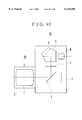
- FIG. 93 is a schematic view of the main parts of a single-lens reflex camera according to a fourth embodiment.
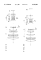
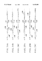
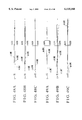
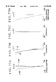
- FIGS. 1 to 16 in lens block diagrams show sixteen numerical examples 1 to 16 of a first embodiment of the invention, respectively.
- Each optical system comprises, in order from an object side, a first lens unit L1 of positive refractive power, a second lens unit L2 of negative refractive power and a third lens unit L3 of positive refractive power.
- the third lens unit L3 includes three lens subunits, i.e., a first lens subunit L31 of positive refractive power, a second lens subunit L32 of negative refractive power and a third lens subunit L33 of positive refractive power.
- SP stands for an aperture stop
- FL stands for an optical filter
- IP stands for an image plane.
- the second lens unit L2 axially moves toward the image side as indicated by an arrow LF. Also, when the optical system vibrates, the shake of the image on the image plane IP is compensated for (or the image is stabilized) by moving the second lens subunit L32 in directions perpendicular to an optical axis, as shown by a double-headed arrow LT.
- the optical system has a feature that, as compared with the first lens unit L1, the second lens unit L2 is small in diameter and far lighter in weight and has a negative refractive power.
- This second lens unit L2 is selected to be used as the focusing lens. So, an electric motor of low torque and small size can be utilized in a drive device therefor.
- Another feature is that the overall refractive power of the first and second lens units L1 and L2 is made positive. As the second lens unit L2 produces a convergent light beam, the first lens subunit L31 further converges it. This makes it easier to minimize the diameter of the second lens subunit L32 (as the image displacement compensating unit).
- the third lens subunit L33 of positive refractive power follows the second lens subunit L32. This allows the negative refractive power of the second lens subunit L32 to increase, while keeping the constant focal length of the entire optical system, thereby making it easier to translate a lesser decentering movement of the second lens subunit L32 to the displacement large enough of the image on the focal plane. (The relationship between the decentered amount and the image displacement is hereinafter called the "image displacement sensitivity”.)
- the present embodiment has set forth such features to stabilize the image well when the user uses the video camera or still camera with the telephoto lens held by his or her hands, or on an unsteady tripod or mono-pod.
- the image shake is compensated for well in such a manner as to assure minimization of the bulk and size of the entire optical system.
- the second lens subunit L32 moves in the directions perpendicular to the optical axis, lesser decentering aberrations, especially coma, astigmatism and field curvature, are produced and a good optical performance is maintained stable throughout the entire focusing range.
- the second lens subunit L32 has an air lens of bi-convex form, and the following condition is satisfied:
- the focal length of an air lens is determined by the refractive indices of the materials disposed before and behind the air lens.
- condition (1) The inequalities of condition (1) are provided for creating the air lens of appropriate shape in the interior of the second lens subunit L32 to obtain a good image quality in either of the normal state (with the image not displaced) and the image-stabilized state.
- the numerical range of the condition (1) is exceeded, it becomes difficult to take a balance of the image quality between the normal state and the image-displayed state.
- the second lens subunit L32 has an air lens of bi-convex form, and the following condition is satisfied: ##EQU1## where Rair1 and Rair2 are radii of curvature of lens surfaces on the object side and the image side of the air lens, respectively.
- condition (2) give an appropriate range for the radii of curvature of lens surfaces on the object side and the image side of the air lens so as to further improve the optical performance.
- range of the condition (2) is exceeded, similarly to the condition (1), it becomes difficult to take a balance of the image quality between the normal state and the image-displaced state.
- condition (3) give a proper range for the refractive power of the positive first lens unit L1.
- the upper limit of the condition (3) is exceeded, as this means that the refractive power of the first lens unit L1 is too weak, the telephoto ability weakens, causing the total length of the entire optical system to increase objectionably.
- the converging action also becomes too weak. Therefore, a bulky light bundle enters the second lens unit L2. To admit of this, the diameter of the second lens unit L2 has to be increased greatly. Also, to keep the constant angle of field, the refractive power of the second lens unit L2 has to be weakened. Therefore, the total focusing movement increases greatly.
- the lower limit is exceeded, as this means that the positive refractive power is too strong, spherical aberrations of high orders are produced, which are hardly corrected by the other lens units.
- condition (4) give a proper range for the refractive power of the focusing, or negative second, lens unit L2.
- the upper limit of the condition (4) is exceeded, the focusing movement from infinity to a certain finite distance increases to hinder minimization of the size of the lens system.
- the second lens unit L2 of negative refractive power can no longer correct the various aberrations, especially spherical aberration, produced by the first lens unit L1 of positive refractive power.
- the lower limit is exceeded, the spherical aberration is over-corrected by the second lens unit L2 of negative refractive power. As a result, it becomes difficult to retain the good correction of the image aberrations.
- condition (5) give a proper range for the refractive power of the third lens unit L3 of positive refractive power.
- the upper limit of the condition (5) is exceeded, too long a back focal distance results. Therefore, the size of the entire optical system is hardly minimized and, moreover, the positive distortion produced by the first lens unit becomes difficult to correct.
- the number of lens elements in the third lens unit has to be increased so as to correct spherical aberration, coma flare or the like.
- the size of the entire optical system is hardly minimized and, moreover, the light transmittance of the optical system worsens. So, these violations are objectionable.
- the inequalities of conditions (6) to (8) give proper ranges for the refractive powers of the lens subunits in the third lens unit, and have an aim that, as the second lens subunit L32 axially moves in the directions perpendicular to the optical axis to stabilize the image, a high sensitivity of image displacement is obtained while still securing the good imaging performance.
- the numerical ranges of these conditions (6) to (8) are exceeded, it becomes difficult to keep the balance therebetween.
- the second lens unit L2 has at least one positive lens and at least one negative lens, and, letting the mean Abbe numbers of materials of the positive lens and the negative lens be denoted by ⁇ p and ⁇ n, respectively, the following condition is satisfied:
- the second lens unit L2 must be decreased in weight to decrease the torque of the focusing driver and the variation with focusing of aberrations must be reduced.
- the inequalities of condition (9) give a proper range for the difference between the Abbe numbers of materials of the positive and negative lenses and have an aim to correct well the variation with focusing of chromatic aberrations.
- two or more negative lenses may be used.
- the second lens subunit L32 consists of, in order from the object side, a positive lens of bi-convex form and two negative lenses of bi-concave form. With this arrangement, when stabilizing the image, the good optical performance is maintained stable.
- the second lens subunit L32 consists of, in order from the object side, a negative lens of meniscus form convex toward the object side, a positive lens of meniscus form convex toward the object side and a negative lens of bi-concave form. With this arrangement, when stabilizing the image, the good optical performance is maintained stable.
- the second lens unit L2 consists of a positive lens and a negative lens. With this arrangement, the variation with focusing of chromatic aberrations is corrected well.
- the third lens subunit L33 has a plurality of positive lenses. To achieve a high sensitivity of image displacement, the third lens subunit L33 is better given a somewhat strong positive refractive power. Particularly for a large relative aperture lens system to achieve, it is preferred that the third lens subunit L33 has a plurality of positive lenses with an advantage of correcting, among others, spherical aberrations of higher orders. If the third lens subunit L33 further includes at least one positive cemented lens composed of negative and positive lenses, or at least one pair of positive and negative lenses with their confronting surfaces of nearly equal radii of curvature to each other, even more improved chromatic aberrations can be expected.
- the first lens sub unit L31 is desired to have at least one positive lens and at least one negative lens.
- the second lens subunit L32 is desired to have a plurality of negative lenses and at least one positive lens.
- the first lens unit L1 is better constructed with a plurality of positive lenses and at least one negative lens. To attain a high image quality, the first lens unit L1 is better constructed with, in order from the object side, a positive lens of bi-convex form, a positive lens whose front surface is strong convex, a bi-concave lens and a positive lens whose front surface is strong convex. More preferably, these lenses are followed by a negative lens of meniscus form convex toward the object side.
- An iris diaphragm may take any position whatever in the lens system, provided that, when stopped down, the light beam which goes to the margin of the useful image circle is not vignetted.
- the iris diaphragm is better positioned in the air space between the second lens unit L2 and the third lens unit L3, or in the interior of the third lens unit L3.
- optical filter FL is positioned in the space between the rearmost lens surface and the image plane, as desired because of assuring minimization of the diameter of the filter and from the point of view of the space efficiency.
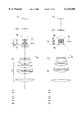
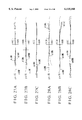
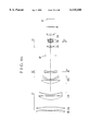
- FIGS. 65 to 69 are lens block diagrams of five numerical examples 17 to 21 of the second embodiment, respectively, where each optical system comprises, in order from an object side, a first lens unit L1 of positive refractive power, a second lens unit L2 of negative refractive power and a third lens unit L3 of positive refractive power.
- the third lens unit L3 comprises a first lens subunit L31 of positive refractive power, a second lens subunit L32 of negative refractive power and a third lens subunit L33 of positive refractive power.
- HG stands for a protection glass
- SP stands for an aperture stop
- FL stands for an optical filter
- FC stands for a flare cut filter
- IP stands for an image plane.
- the second lens unit L2 is made to axially move toward the image side, during focusing from an infinitely distant object to an object at the minimum distance, as indicated by an arrow LF.
- the second lens subunit L32 is a movable lens subunit (image displacement compensation unit) which is made to move in directions perpendicular to an optical axis as indicated by a double-headed arrow LT, so as to compensate for the shake of the image when the optical system vibrates.
- the optical system has the following features.
- the second lens unit L2 of negative refractive power has a small diameter and a far lighter weight. So, the second lens unit L2 is selected to be used as the focusing lens. Therefore, a driving device used for the second lens unit L2 is of low torque and small size.
- the light beam emerging from the second lens unit L2 is made to converge in passing through the first lens subunit L31 of positive refractive power. This makes it easier to minimize the diameter of the second lens subunit L32 (image displacement compensation unit).
- the use of the third lens subunit L33 of positive refractive power allows the negative refractive power of the second lens subunit L32 to increase, while keeping the constant focal length of the entire optical system. Accordingly, the decentering movement of the second lens subunit L32 can be reduced to effect the equivalent displacement of the image on the focal plane. The image is thus quickly stabilized.
- the present embodiment has set forth such features to stabilize the image with good reliability and ease when the video camera or still camera is equipped with the telephoto lens and when the user holds it by his or her hands, or on an unsteady tripod or mono-pod.
- the optical system of the present embodiment is of the inner focus type and has the image stabilizing function, as described above.
- the optical system comprises, in order from the object side, the first lens unit L1 of positive refractive power, the second lens unit L2 of negative refractive power and the third lens unit L3 of positive refractive power, totaling three lens units
- the third lens unit L3 comprises, in order from the object side, the first lens subunit L31 of positive refractive power, the second lens subunit L32 of negative refractive power and the third lens subunit L33 of positive refractive power, totaling three subunits, wherein the second lens unit L2 moves along the optical axis to effect focusing and the second lens subunit L32 moves in the directions perpendicular to the optical axis to displace the image position for the purpose of stabilizing the image on the focal plane.
- optical system according to the present embodiment satisfies the following condition (10) and/or conditions (11) to (13):
- f1-2 the overall focal length of the first and second lens units
- the inequality of condition (10) means that the overall focal length f1-2 of the first and second lens units L1 and L2 is not less than 10 times longer than the focal length f of the entire optical system. In other words, the light beam after having passed through the first and second lens units L1 and L2 is made almost afocal.
- the condition (10) is satisfied for moderating the accuracy of setting up the second and third lens units L2 and L3 on the assembly line.
- all the optical parameters of each lens unit are so determined as to satisfy the conditions (11), (12) and (13).
- the requirements of minimizing the size of the entire optical system and of well stabilizing the image are thus fulfilled at once.
- the produced amount of decentering aberrations, especially decentering coma, decentering astigmatism and decentering field curvature is reduced and a good optical performance is maintained stable throughout the entire focusing range.
- condition (11) give a proper range for the positive refractive power of the first lens unit L1.
- the upper limit of the condition (11) is exceeded, as this means that the refractive power of the first lens unit L1 is too weak, the telephoto system produces a weak effect, causing the total length of the entire optical system to increase objectionably. The converging action also becomes too weak. Therefore, a bulky light bundle enters the second lens unit L2. To admit of this, the diameter of the second lens unit L2 has to increase largely.
- the lower limit is exceeded, as this means that the positive refractive power is too strong, spherical aberrations of higher orders are produced, which are hardly corrected by the other lens units.
- condition (12) The inequalities of condition (12) are provided for determining the refractive powers of the negative second or focusing lens unit L2 and the positive first lens unit L1 in appropriate relation.
- the various aberrations, especially spherical aberration, produced by the first lens unit L1 of positive refractive power can be no longer corrected by the second lens unit L2 of negative refractive power.
- the spherical aberration is over-corrected by the second lens unit L2. As a result, the whole optical system hardly retains the good optical performance.
- condition (13) give a proper range for the refractive power of the positive third lens unit L3.
- the upper limit of the condition (13) is exceeded, too long a back focal distance results. Therefore, the size of the entire optical system is hardly minimized and, moreover, the positive distortion produced by the first lens unit L1 becomes difficult to correct.
- the rules of lens design are set forth to compensate for the shake of the image on the focal plane when the optical system vibrates, while still permitting the variation with vibration of decentering aberrations to be reduced to a minimum and also maintaining good stability of optical performance throughout the entire focusing range.
- the second lens unit has two negative lenses and one positive lens.
- the second lens unit L2 is made constructed with at least two negative lenses and at least one positive lenses, thereby making it easy to maintain good stability of correction of various aberrations. Further, when the condition (14) is satisfied, the second lens unit L2 is determined to have so appropriate a refractive power that a relatively small movement of the second lens unit L2 suffices for focusing from an infinitely distant object to an object at the minimum distance.
- the inequalities of conditions (15) to (17) are provided for assuring that, as the second lens subunit L32 moves in the directions perpendicular to the optical axis to displace the image position, the sensitivity of image displacement gets high enough, while still maintaining good image quality to be achieved.
- the numerical ranges of these conditions (15) to (17) are exceeded, it becomes difficult to keep the balance therebetween.
- the first lens subunit L31 is better corrected for longitudinal chromatic aberration.
- the first lens subunit L31 is desired to have at least one positive lens and at least one negative lens.
- the second lens subunit L32 comprises a plurality of negative lenses and at least one positive lens. This makes it easier to reduce the variation of chromatic aberrations and other aberrations when stabilizing the image.
- the third lens subunit L33 is better given a somewhat strong positive refractive power. Particularly for a large-relative-aperture lens system to achieve, it is preferred that the third lens subunit L33 has a plurality of positive lenses with an advantage of correcting, among others, spherical aberrations of higher orders. If the third lens subunit L33 further includes at least one positive cemented lens composed of negative and positive lenses, or at least one pair of positive and negative lenses with their confronting surfaces of nearly equal radii of curvature to each other, even more improved chromatic aberrations can be expected.
- the first lens unit L1 is better constructed with a plurality of positive lenses and at least one negative lens. To attain a high image quality, the first lens unit L1 is better constructed with, in order from the object side, a positive lens, a positive lens, a bi-concave lens, a negative lens of meniscus form convex toward the object side and a positive lens having a strong convex surface facing the object side.
- An iris diaphragm may take any position whatever in the lens system, provided that, when stopped down, the light beam which goes to the margin of the useful image circle is not vignetted.
- the iris diaphragm is better positioned in the air space between the second and third lens units L2 and L3, or in the interior of the third lens unit L3.
- the optical filter FL is positioned in the space between the rearmost lens surface and the image plane, as desired because of assuring minimization of the diameter of the filter and from the point of view of the space efficiency.
- the optical system is provided with means for moving one of the lens units in part in the directions perpendicular to the optical axis to thereby compensate for the shake of the image on the focal plane.
- certain lens parameters are appropriately determined to correct all decentering aberrations well.
- the required decentering movement for the large enough displacement compensation (image stabilization) is made short enough to realize minimization of the bulk and size of the apparatus that uses the optical system.
- the variation with focusing of aberrations is corrected well throughout a wide range of object distances.
- An optical system of the inner focus type having the image stabilizing function which accomplishes the objects of the invention is thus achieved.
- a further embodiment of the invention is next described which is particularly adapted to a further reduction of the variation with focusing of aberrations.
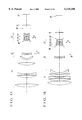
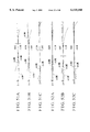
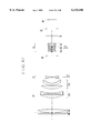
- FIGS. 85 to 88 are lens block diagrams of four numerical examples 22 to 25 of the third embodiment, respectively.
- FIGS. 89A to 89D through FIGS. 92A to 92D show the aberrations of the numerical examples 22 to 25, respectively.
- the optical system comprises, in order from an object side, a first lens unit L1 of positive refractive power, a second lens unit L2 of negative refractive power and a third lens unit L3 of positive refractive power.
- the first lens unit L1 consists of, with boundaries formed by the widest and the second-widest spaces thereof, in order from the object side, a front lens subunit L1a of positive refractive power, a middle lens subunit L1b of negative refractive power and a rear lens subunit L1c of positive refractive power.
- the third lens unit L3 comprises, in order from the object side, a first lens subunit L3a of positive refractive power, a second lens subunit L3b of negative refractive power and a third lens subunit L3c of positive refractive power.
- SP stands for an aperture stop
- FL stands for an optical filter
- IP stands for an image plane
- FC stands for a flare cut filter
- HG stands for a protection glass plate.
- focusing is performed by axially moving the second lens unit L2 toward the image side, as indicated by an arrow LF, when the object distance decreases from infinity to a minimum.
- the first lens unit on which the light beam is incident at a great height and which is relatively easy to correct for aberrations is made constructed with three lens subunits.
- the focal length f1a of the front lens subunit L1a and the space D1ab between the front lens subunit L1a and the middle lens subunit L1b are so determined as to satisfy the following conditions:
- f is the focal length of the entire optical system. This achieves an optical system whose image aberrations are corrected well over the entire area of the image frame and which, during focusing, varies the aberrations to a lesser extent for high optical performance.
- the shake of the image on the focal plane is compensated for by moving the second lens subunit L3b in directions perpendicular to an optical axis, as indicated by a double-headed arrow LT.
- the second lens unit L2 of negative refractive power has a small diameter and a far light weight. Focusing is carried out by axially moving the second lens unit L2. Therefore, a driving device to used for the second lens unit L2 is of low torque and small size. Also, the combined refractive power of the first and second lens units L1 and L2 is made positive. The light beam emerging from the second lens unit L2 is then made to further converge in passing through the first lens subunit L3a of positive refractive power. This makes it easier to minimize the diameter of the second lens subunit L3b (image displacement compensation unit).
- the third lens subunit L3c of positive refractive power is used to allow the negative refractive power of the second lens subunit L3b to increase, while keeping the constant focal length of the entire optical system. So, the decentering movement of the second lens subunit L3b can be reduced to effect the equivalent displacement of the image on the focal plane. The image is thus quickly stabilized.
- the weight of the telephoto lens increases rapidly. A large proportion of this increase owes to the increase of the diameter of the front or first lens unit. Accordingly, the lighter the weight of the first lens unit, the greater the effect of reducing the weight of the entire optical system is produced. As is apparent from the above-described formula for the F-number, the effective diameter of the frontmost lens members is hardly much reduced. For the weight of the first lens unit to reduce, therefore, an appropriate arrangement of the other lens members than the frontmost ones has better be made.
- the first lens unit L1 is constructed from three lens subunits. That is, the front lens subunit L1a of positive refractive power precedes on the object side. The light beam emerging from the front lens subunit L1a is thus made to converge. The middle lens subunit L1b is then adjusted to an appropriate position. The weight of the section that follows the front lens subunit L1a is thus reduced. Further, the middle lens subunit L1b is made negative in refractive power, giving an advantage of reducing the spherical aberration and longitudinal chromatic aberration produced in the front lens subunit L1a.
- the rear lens subunit L1c that is put on the image side of the middle lens subunit L1b is made positive in refractive power, supplementing for the positive refractive power necessary to the first lens unit L1.
- the inequalities of condition (18) give a proper range for the refractive power of the front lens subunit L1a.
- the upper limit is exceeded, as this means that the refractive power of the front lens subunit L1a is too weak, the light beam emerging from the front lens subunit L1a converges insufficiently. Therefore, it becomes difficult to reduce the weight of the section that lies on the image side of the front lens subunit L1a.
- the lower limit is exceeded, the front lens subunit L1a produces too much large spherical aberration which is difficult to correct.
- the inequalities of condition (19) give a proper range for the air separation between the front lens subunit L1a and the middle lens subunit L1b.
- the upper limit is exceeded, the light beam entering the middle lens subunit L1b becomes too much convergent. Therefore, the spherical aberration produced by the front lens subunit L1a is hardly reduced by the middle lens subunit L1b.
- the lower limit is exceeded, the light beam entering the middle lens subunit L1b converges insufficiently. Therefore, it becomes difficult to reduce the weight of the optical system.
- the front lens subunit L1a consists of one positive lens 1ap
- the middle lens subunit L1b consists of a positive lens 1 bp and a negative lens 1bn.
- the middle and rear lens subunits L1b and L1c have focal lengths f1b and f1c, respectively, lying in the following respective ranges
- the positive lenses 1ap and 1bp are made up from materials whose refractive indices N1ap and N1bp and Abbe numbers ⁇ 1ap and ⁇ 1bp, respectively, lie in the following respective ranges:
- the front lens subunit L1a is constructed with a single lens, thus reducing the weight of the first lens unit L1.
- the middle lens subunit L1b is constructed with the positive and negative lenses 1bp and 1bn in this order from the object side, thereby shifting the principal point of the middle lens subunit L1b to the object side. The separation between the front and middle lens subunits L1a and L1b is thus secured without any stress.
- condition (20) give a proper range for the refractive power of the middle lens subunit L1b.
- condition (20) is satisfied, it becomes even easier to make a good compromise between the reduction of spherical aberration produced in the front lens subunit L1a and the holding of the positive refractive power of the whole first lens unit L1.
- condition (21) give a proper range for the refractive power of the rear lens subunit L1c.
- condition (21) is satisfied, it becomes even easier to make good compromise between the holding of the positive refractive power of the whole first lens unit L1 and the convergence of the light beam emerging from the front lens subunit L1a.
- condition (22) is a condition for specifying materials in Abbe number for the positive lens 1ap of the front lens subunit L1a.
- condition (22) is satisfied, the negative longitudinal chromatic aberration in the image plane becomes easy to correct.
- condition (23) is a condition for specifying materials in refractive index for the positive lens 1ap of the front lens subunit L1a.
- condition (23) is satisfied, the spherical aberration in the image plane becomes easy to correct.
- condition (24) is a condition for specifying materials in Abbe number for the positive lens 1bp of the middle lens subunit L1b.
- condition (24) is satisfied, the negative longitudinal chromatic aberration in the image plane becomes easy to correct.
- condition (25) is a condition for specifying materials in refractive index for the positive lens 1bp of the middle lens subunit L1b.
- condition (25) is satisfied, the spherical aberration in the image plane becomes easy to correct.
- the rear lens subunit L1c consists of a positive lens 1cp and a negative lens 1cn of meniscus form convex toward the object side.
- the rear lens subunit L1c Since the rear lens subunit L1c has a positive refractive power, a positive lens is required. Further, the use of a negative lens makes it easy to correct the spherical aberration of the whole first lens unit L1. Furthermore, the negative lens is formed to a meniscus form convex toward the object side. With this arrangement, even comatic aberration is made easy to correct.
- the second lens unit L2 has a cemented lens composed of a positive lens and a negative lens, and the focal length f2 of the second lens unit L2 lies in the following range:
- the telephoto lenses have loose power arrangement and still are long and bulky. Therefore, focusing by bodily moving the entire optical system is hardly carried out. For this reason, the focusing provision has been made in part of the optical system. That is, either of the so-called “inner” and “rear” focusing methods has been employed.
- the second lens unit L2 takes a place where the light beam after being converged by the first lens unit L1 arrives at and, therefore, gets a relatively small diameter. This leads to simplify the structure of the focusing control mechanism.
- the second lens unit L2 is constructed in the form of the positive and negative lenses cemented to a single cemented lens. The variation with focusing of longitudinal chromatic aberration is thus removed and, moreover, the focusing control mechanism is further simplified in structure.
- the inequalities of condition (26) give a proper range for the refractive power of the second lens unit L2.
- the second lens unit L2 as used for focusing has to move too much long a distance, causing the bulk and size of the entire optical system to increase greatly and the focusing control mechanism to get more complicated in structure.
- the lower limit it becomes difficult to remove the variation with focusing of longitudinal chromatic aberration.
- the optical system of the inner focus type described above has the third lens unit L3 of positive refractive power on the image side of the second lens unit L2.
- the third lens unit L3 comprises, in order from the object side, the first lens subunit L3a of positive refractive power, the second lens subunit L3b of negative refractive power and the third lens subunit L3c of positive refractive power, totaling three lens subunits.
- the second lens subunit L3b is arranged to move in the directions perpendicular to the optical axis to effect stabilizing of the image on the focal plane.
- the inequalities of conditions (27) to (29) are provided for assuring that, as the second lens subunit L3b moves in the directions perpendicular to the optical axis to displace the image position, the sensitivity of image displacement gets high enough, while still maintaining good image quality to be achieved. When these conditions (27) to (29) are violated, it becomes difficult to keep the balance therebetween.
- the second lens subunit L3b comprises a plurality of negative lenses and one positive lens.
- the third lens subunit L3c comprises a plurality of positive lenses.
- the second lens subunit L3b has a plurality of negative lenses and at least one positive lens, it becomes possible to suppress the variation with image stabilizing of chromatic aberrations and other aberrations to a minimum. Also, to achieve a high sensitivity of image displacement, there is need to give the third lens subunit L3c a somewhat strong positive refractive power. Particularly for a telephoto lens of such a large relative aperture as in the invention to achieve, the third lens subunit L3c is better constructed with a plurality of positive lenses with an advantage of correcting, among others, spherical aberrations of higher orders.
- (c-7) To protect the exposed lens surface to the outside and to prevent occurrence of a change of the position of the sharp focus owing to the expansion or contraction of the lens elements with change of the ambient temperature, use may be made of a flat glass plate or transparent member or a lens of weak refractive power on the object side of the lens system.
- An iris diaphragm may take any position whatever in the lens system, provided that, when stopped down, the light beam which goes to the margin of the useful image circle is not vignetted.
- the iris diaphragm is better positioned in the air space between the second and third lens units L2 and L3, or in the interior of the third lens unit L3.
- the optical filter FL is positioned in the space between the rearmost lens surface and the image plane, as desired because of assuring minimization of the diameter of the filter and from the point of view of the space efficiency.
- the rules of design are set forth to correct well the variation with focusing of aberrations over a wide range of object distance, thus making it possible to achieve an optical system having a high optical performance despite the use of the inner focus type.
- Such an optical system is also provided with means for moving one of the lens units in part in the directions perpendicular to the optical axis to thereby compensate for the shake of the image on the focal plane.
- certain lens parameters are appropriately determined to correct all decentering aberrations well.
- FIG. 93 is a schematic section view of the main parts of a single-lens reflex camera.
- a photographic lens 10 contains an optical system 1 according to one of the first to third embodiments.
- the optical system 1 is housed within a holding member or outer barrel 2.
- a camera body 20 contains a quick-return mirror 3 in the viewing position where the light beam from the photographic lens 10 is reflected upward to a focusing screen 4.
- the inverted image formed on the focusing screen 4 is erected and laterally reversed by a pentagonal roof prism 5.
- the erected image is viewed by looking through an eyepiece lens 6.
- a film surface 7 is disposed on an image plane.
- the quick-return mirror 3 is retracted from the optical path so that an image of an object being photographed is formed on the film surface 7 by the photographic lens 10.
Landscapes
- Physics & Mathematics (AREA)
- General Physics & Mathematics (AREA)
- Optics & Photonics (AREA)
- Lenses (AREA)
Abstract
An optical system includes, in order from an object side, a first lens unit of positive refractive power, a second lens unit of negative refractive power, the second lens unit being movable along an optical axis to effect focusing, and a third lens unit of positive refractive power, the third lens unit including, in order from the object side, a first lens subunit of positive refractive power, a second lens subunit of negative refractive power and a third lens subunit of positive refractive power, wherein the second lens subunit is movable in directions perpendicular to the optical axis to displace an image formed by the optical system.
Description
1. Field of the Invention
The present invention relates to optical systems of the inner focus type suited to cameras for film, video cameras, video still cameras or the like.
2. Description of Related Art
It has been known to provide a lens type suited to the optical systems of long focal lengths, comprising, in order from an object side, a first lens unit of positive refractive power and a second lens unit of negative refractive power, or the so-called "telephoto" type. This lens type is advantageous at removing, in particular, spherical aberration and securing a fast F-number.
In, for example, Japanese Laid-Open Patent Applications No. Hei 5-27163, No. Hei 5-27164, No. Hei 6-242371, No. Hei 9-159911 and No. Hei 9-203859, the use of the telephoto type in optical systems has been proposed.
For many photographic lenses (optical systems,) focusing is performed by moving either the entirety of the complete lens, or one of the constituent lenses. In the case of long-focal-length lenses or telephoto lenses, because of their having bodies of large size and heavy weight, the former focusing method is hardly employed owing to the difficult problem of making up the operating mechanism.
For this reason, most of the telephoto lenses have the focusing provision made in one of the lens units. Of the lens units other than the front lens unit, a one in the central section is favorable for focusing purposes, because its size is relatively small and, moreover, because it is far light in weight. The use of this inner focus type has been proposed for various lenses.
For example, Japanese Laid-Open Patent Application No. Sho 55-147606 (U.S. Pat. No. 4,348,084) discloses a telephoto lens of the inner focus type having a focal length of 300 mm with an F-number of 2.8, and each of Japanese Laid-Open Patent Applications No. Sho 59-65820 and No. Sho 59-65821 discloses another telephoto lens of the inner focus type having a focal length of 135 mm with an F-number of 2.8.
The telephoto lenses of the inner focus type proposed in the above applications each comprise, in order from an object side, a first lens unit of positive refractive power, a second lens unit of negative refractive power and a third lens unit of positive refractive power, totaling three lens units, wherein the second lens unit is made axially movable for focusing.
Meanwhile, in shooting with the long-focal-length photographic system (optical system), it is generally difficult to suppress the influence of the vibrations of the photographic system. When the photographic system tilts due to the vibrations, the image on the focal plane changes its position out of alignment with a sight line, depending on the tilt angle and the focal length of the photographic system. Therefore, the photographic apparatus for taking still pictures suffers a problem of preventing the image quality from deteriorating by decreasing the exposure time to much short values. The motion-picture taking apparatus, too, encounters a difficult problem of keeping the composition at a desired setting. In such photographic situations, therefore, it becomes necessary to compensate for the tilting of the photographic system due to the vibrations so that the image on the focal plane remains stationary in alignment with the line of sight, that is, the so-called "shake" of the image does not occur.
There have been many methods of compensating for the shake of the image on the focal plane. For example, in the video cameras, the image pickup element is given a larger effective area than the necessary image frame and the image shake is electrically compensated for. Such an electric compensation method is widely employed in the video cameras.
In Japanese Laid-Open Patent Application No. Sho 61-223819, there is disclosed a photographic system in which a refractive-type variable angle prism is disposed at the frontmost position thereof. When the photographic system vibrates, the vertical angle of the variable angle prism is changed correspondingly with the vibration of the photographic system, so that an image is deflected so as to stabilize the image.
Another method of compensating for the shake of the image by moving a certain lens unit (movable lens unit) of an optical system in directions perpendicular to the optical axis was proposed in, for example, Japanese Laid-Open Patent Applications No. Sho 50-80147, No. Sho 61-223819, No. Hei 7-270724 (U.S. Pat. No. 5,646,779) and No. Hei 8-201691.
With such an optical system, if the relative aperture is increased (or if the F-number is made faster), the front lens unit becomes larger accordingly. As is well known, the F-number of the optical system is defined by
Fno=f/D
where Fno: the F-number,
f: the focal length of the optical system, and
D: the diameter of an effective light beam coming from an object point at infinity on the optical axis.
Accordingly, the large-relative-aperture telephoto lens (whose focal length is long) gets a large diameter for the equivalent F-number in direct proportion to the focal length. As the diameter of the front lens unit increases, the weight of the optical system increases rapidly. So, this tendency has been seen as problematic. Particularly for the photographic camera using 35 mm film, in the case of exceeding f=400 mm (semi-angle of field ω=3.1°), or in the case of the so-called "super" telephoto lens, this problem is very serious. In the locations where the tripod cannot be used, the hand-held shooting gives the photographer a heavy burden, becoming a cause of the image shake and an obstacle to the long-time shooting.
The method of compensating for the shake of the image by decentering a certain movable lens unit of the optical system so as to displace the image position is amenable to the techniques of minimizing the size of the apparatus by selecting a suitable one of the lens units for the movable lens unit.
However, the use of this method leads to taking into account two prerequisites, one of which is to properly select or arrange a lens unit of small size and light weight so that a lesser decentering movement produces a greater effect of displacing the image position, and the other of which is to prevent the image quality from deteriorating as far as possible, as that lens unit, when being decentered, produces aberrations. In general, it is very difficult to balance these conditions.
Meanwhile, the inner focus type, because of its using a lens unit of small size and light weight as the focusing lens, has merits that the management is easy, that a fast speed operation becomes possible, and that the holding is easy to keep, because the center of gravity of the whole lens system little changes between when focused on an infinitely distant object and when focused on an object at the minimum distance.
On the other hand, the use of the inner focus type in the telephoto lens of fast F-number increases the range of variation of aberrations with focusing. This variation of aberrations, because of being difficult to correct well, comes to a cause of lowering the optical performance.
The present invention is concerned with the image stabilizing function in the optical system which makes one lens unit movable to decenter in directions perpendicular to an optical axis. With this regard, an object of the invention is to provide an optical system which can manifest the image stabilizing function, while still permitting the decentering aberrations to be as far suppressed as possible.
The present invention is concerned also with the inner focus type. Another object of the invention is, therefore, to provide an optical system which suppresses the variation with focusing of aberrations as far as possible over a wide range of object distances.
To attain the former object, in accordance with an aspect of the invention, there is provided an optical system, which comprises, in order from an object side, a first lens unit of positive refractive power, a second lens unit of negative refractive power, the second lens unit being movable along an optical axis to effect focusing, and a third lens unit of positive refractive power, the third lens unit including, in order from the object side, a first lens subunit of positive refractive power, a second lens subunit of negative refractive power and a third lens subunit of positive refractive power, wherein the second lens subunit is movable in directions perpendicular to the optical axis to displace an image formed by the optical system.
To attain the latter object, in accordance with another aspect of the invention, there is provided an optical system, which comprises, in order from an object side, a first lens unit of positive refractive power, the first lens unit consisting of, with boundaries formed by the widest and the second-widest spaces thereof, in order from the object side, a front lens subunit of positive refractive power, a middle lens subunit of negative refractive power and a rear lens subunit of positive refractive power, and a second lens unit of negative refractive power, the second lens unit being movable along an optical axis to effect focusing, wherein, letting a focal length of the entire optical system be denoted by f, a focal length of the front lens subunit be denoted by f1a, and a space between the front lens subunit and the rear lens subunit be denoted by D1ab, the following conditions are satisfied:
0.4<f1a/f<1.1
0.035<D1ab/f<0.15.
These and further objects and aspects of the invention will become apparent from the following detailed description of preferred embodiments thereof taken in conjunction with the accompanying drawings.
FIG. 1 is a longitudinal section view of a numerical example 1 of the lens.
FIG. 2 is a longitudinal section view of a numerical example 2 of the lens.
FIG. 3 is a longitudinal section view of a numerical example 3 of the lens.
FIG. 4 is a longitudinal section view of a numerical example 4 of the lens.
FIG. 5 is a longitudinal section view of a numerical example 5 of the lens.
FIG. 6 is a longitudinal section view of a numerical example 6 of the lens.
FIG. 7 is a longitudinal section view of a numerical example 7 of the lens.
FIG. 8 is a longitudinal section view of a numerical example 8 of the lens.
FIG. 9 is a longitudinal section view of a numerical example 9 of the lens.
FIG. 10 is a longitudinal section view of a numerical example 10 of the lens.
FIG. 11 is a longitudinal section view of a numerical example 11 of the lens.
FIG. 12 is a longitudinal section view of a numerical example 12 of the lens.
FIG. 13 is a longitudinal section view of a numerical example 13 of the lens.
FIG. 14 is a longitudinal section view of a numerical example 14 of the lens.
FIG. 15 is a longitudinal section view of a numerical example 15 of the lens.
FIG. 16 is a longitudinal section view of a numerical example 16 of the lens.
FIGS. 17A to 17D are graphic representations of the longitudinal aberrations of the numerical example 1 in the normal state (with the image position unchanged).
FIGS. 18A to 18C are graphic representations of the lateral aberrations of the numerical example 1 in the normal state (with the image position unchanged).
FIGS. 19A to 19C are graphic representations of the lateral aberrations of the numerical example 1 when the image of an infinitely distant object has displaced to a corresponding position to 0.3° in image angle.
FIGS. 20A to 20D are graphic representations of the longitudinal aberrations of the numerical example 2 in the normal state (with the image position unchanged).
FIGS. 21A to 21C are graphic representations of the lateral aberrations of the numerical example 2 in the normal state (with the image position unchanged).
FIGS. 22A to 22C are graphic representations of the lateral aberrations of the numerical example 2 when the image of an infinitely distant object has displaced to a corresponding position to 0.3° in image angle.
FIGS. 23A to 23D are graphic representations of the longitudinal aberrations of the numerical example 3 in the normal state (with the image position unchanged).
FIGS. 24A to 24C are graphic representations of the lateral aberrations of the numerical example 3 in the normal state (with the image position unchanged).
FIGS. 25A to 25C are graphic representations of the lateral aberrations of the numerical example 3 when the image of an infinitely distant object has displaced to a corresponding position to 0.3° in image angle.
FIGS. 26A to 26D are graphic representations of the longitudinal aberrations of the numerical example 4 in the normal state (with the image position unchanged).
FIGS. 27A to 27C are graphic representations of the lateral aberrations of the numerical example 4 in the normal state (with the image position unchanged).
FIGS. 28A to 28C are graphic representations of the lateral aberrations of the numerical example 4 when the image of an infinitely distant object has displaced to a corresponding position to 0.3° in image angle.
FIGS. 29A to 29D are graphic representations of the longitudinal aberrations of the numerical example 5 in the normal state (with the image position unchanged).
FIGS. 30A to 30C are graphic representations of the lateral aberrations of the numerical example 5 in the normal state (with the image position unchanged).
FIGS. 31A to 31C are graphic representations of the lateral aberrations of the numerical example 5 when the image of an infinitely distant object has displaced to a corresponding position to 0.3° in image angle.
FIGS. 32A to 32D are graphic representations of the longitudinal aberrations of the numerical example 6 in the normal state (with the image position unchanged).
FIGS. 33A to 33C are graphic representations of the lateral aberrations of the numerical example 6 in the normal state (with the image position unchanged).
FIGS. 34A to 34C are graphic representations of the lateral aberrations of the numerical example 6 when the image of an infinitely distant object has displaced to a corresponding position to 0.3° in image angle.
FIGS. 35A to 35D are graphic representations of the longitudinal aberrations of the numerical example 7 in the normal state (with the image position unchanged).
FIGS. 36A to 36C are graphic representations of the lateral aberrations of the numerical example 7 in the normal state (with the image position unchanged).
FIGS. 37A to 37C are graphic representations of the lateral aberrations of the numerical example 7 when the image of an infinitely distant object has displaced to a corresponding position to 0.3° in image angle.
FIGS. 38A to 38D are graphic representations of the longitudinal aberrations of the numerical example 8 in the normal state (with the image position unchanged).
FIGS. 39A to 39C are graphic representations of the lateral aberrations of the numerical example 8 in the normal state (with the image position unchanged).
FIGS. 40A to 40C are graphic representations of the lateral aberrations of the numerical example 8 when the image of an infinitely distant object has displaced to a corresponding position to 0.3° in image angle.
FIGS. 41A to 41D are graphic representations of the longitudinal aberrations of the numerical example 9 in the normal state (with the image position unchanged).
FIGS. 42A to 42C are graphic representations of the lateral aberrations of the numerical example 9 in the normal state (with the image position unchanged).
FIGS. 43A to 43C are graphic representations of the lateral aberrations of the numerical example 9 when the image of an infinitely distant object has displaced to a corresponding position to 0.3° in image angle.
FIGS. 44A to 44D are graphic representations of the longitudinal aberrations of the numerical example 10 in the normal state (with the image position unchanged).
FIGS. 45A to 45C are graphic representations of the lateral aberrations of the numerical example 10 in the normal state (with the image position unchanged).
FIGS. 46A to 46C are graphic representations of the lateral aberrations of the numerical example 10 when the image of an infinitely distant object has displaced to a corresponding position to 0.3° in image angle.
FIGS. 47A to 47D are graphic representations of the longitudinal aberrations of the numerical example 11 in the normal state (with the image position unchanged).
FIGS. 48A to 48C are graphic representations of the lateral aberrations of the numerical example 11 in the normal state (with the image position unchanged).
FIGS. 49A to 49C are graphic representations of the lateral aberrations of the numerical example 11 when the image of an infinitely distant object has displaced to a corresponding position to 0.3° in image angle.
FIGS. 50A to 50D are graphic representations of the longitudinal aberrations of the numerical example 12 in the normal state (with the image position unchanged).
FIGS. 51A to 51C are graphic representations of the lateral aberrations of the numerical example 12 in the normal state (with the image position unchanged).
FIGS. 52A to 52C are graphic representations of the lateral aberrations of the numerical example 12 when the image of an infinitely distant object has displaced to a corresponding position to 0.3° in image angle.
FIGS. 53A to 53D are graphic representations of the longitudinal aberrations of the numerical example 13 in the normal state (with the image position unchanged).
FIGS. 54A to 54C are graphic representations of the lateral aberrations of the numerical example 13 in the normal state (with the image position unchanged).
FIGS. 55A to 55C are graphic representations of the lateral aberrations of the numerical example 13 when the image of an infinitely distant object has displaced to a corresponding position to 0.3° in image angle.
FIGS. 56A to 56D are graphic representations of the longitudinal aberrations of the numerical example 14 in the normal state (with the image position unchanged).
FIGS. 57A to 57C are graphic representations of the lateral aberrations of the numerical example 14 in the normal state (with the image position unchanged).
FIGS. 58A to 58C are graphic representations of the lateral aberrations of the numerical example 14 when the image of an infinitely distant object has displaced to a corresponding position to 0.3° in image angle.
FIGS. 59A to 59D are graphic representations of the longitudinal aberrations of the numerical example 15 in the normal state (with the image position unchanged).
FIGS. 60A to 60C are graphic representations of the lateral aberrations of the numerical example 15 in the normal state (with the image position unchanged).
FIGS. 61A to 61C are graphic representations of the lateral aberrations of the numerical example 15 when the image of an infinitely distant object has displaced to a corresponding position to 0.3° in image angle.
FIGS. 62A to 62D are graphic representations of the longitudinal aberrations of the numerical example 16 in the normal state (with the image position unchanged).
FIGS. 63A to 63C are graphic representations of the lateral aberrations of the numerical example 16 in the normal state (with the image position unchanged).
FIGS. 64A to 64C are graphic representations of the lateral aberrations of the numerical example 16 when the image of an infinitely distant object has displaced to a corresponding position to 0.3° in image angle.
FIG. 65 is a longitudinal section view of a numerical example 17 of the lens.
FIG. 66 is a longitudinal section view of a numerical example 18 of the lens.
FIG. 67 is a longitudinal section view of a numerical example 19 of the lens.
FIG. 68 is a longitudinal section view of a numerical example 20 of the lens.
FIG. 69 is a longitudinal section view of a numerical example 21 of the lens.
FIGS. 70A to 70D are graphic representations of the longitudinal aberrations of the numerical example 17 in the normal state (with the image position unchanged).
FIGS. 71A to 71E are graphic representations of the lateral aberrations of the numerical example 17 in the normal state (with the image position unchanged).
FIGS. 72A to 72C are graphic representations of the lateral aberrations of the numerical example 17 when the image of an infinitely distant object has displaced to a corresponding position to 0.5° in image angle.
FIGS. 73A to 73D are graphic representations of the longitudinal aberrations of the numerical example 18 in the normal state (with the image position unchanged).
FIGS. 74A to 74E are graphic representations of the lateral aberrations of the numerical example 18 in the normal state (with the image position unchanged).
FIGS. 75A to 75C are graphic representations of the lateral aberrations of the numerical example 18 when the image of an infinitely distant object has displaced to a corresponding position to 0.5° in image angle.
FIGS. 76A to 76D are graphic representations of the longitudinal aberrations of the numerical example 19 in the normal state (with the image position unchanged).
FIGS. 77A to 77E are graphic representations of the lateral aberrations of the numerical example 19 in the normal state (with the image position unchanged).
FIGS. 78A to 78C are graphic representations of the lateral aberrations of the numerical example 19 when the image of an infinitely distant object has displaced to a corresponding position to 0.5° in image angle.
FIGS. 79A to 79D are graphic representations of the longitudinal aberrations of the numerical example 20 in the normal state (with the image position unchanged).
FIGS. 80A to 80E are graphic representations of the lateral aberrations of the numerical example 20 in the normal state (with the image position unchanged).
FIGS. 81A to 81C are graphic representations of the lateral aberrations of the numerical example 20 when the image of an infinitely distant object has displaced to a corresponding position to 0.5° in image angle.
FIGS. 82A to 82D are graphic representations of the longitudinal aberrations of the numerical example 21 in the normal state (with the image position unchanged).
FIGS. 83A to 83E are graphic representations of the lateral aberrations of the numerical example 21 in the normal state (with the image position unchanged).
FIGS. 84A to 84C are graphic representations of the lateral aberrations of the numerical example 21 when the image of an infinitely distant object has displaced to a corresponding position to 0.5° in image angle.
FIG. 85 is a longitudinal section view of a numerical example 22 of the lens.
FIG. 86 is a longitudinal section view of a numerical example 23 of the lens.
FIG. 87 is a longitudinal section view of a numerical example 24 of the lens.
FIG. 88 is a longitudinal section view of a numerical example 25 of the lens.
FIGS. 89A to 89D are graphic representations of the various aberrations of the numerical example 22.
FIGS. 90A to 90D are graphic representations of the various aberrations of the numerical example 23.
FIGS. 91A to 91D are graphic representations of the various aberrations of the numerical example 24.
FIGS. 92A to 92D are graphic representations of the various aberrations of the numerical example 25.
FIG. 93 is a schematic view of the main parts of a single-lens reflex camera according to a fourth embodiment.
Hereinafter, preferred embodiments of the invention will be described in detail with reference to the drawings.
(First Embodiment)
FIGS. 1 to 16 in lens block diagrams show sixteen numerical examples 1 to 16 of a first embodiment of the invention, respectively. Each optical system comprises, in order from an object side, a first lens unit L1 of positive refractive power, a second lens unit L2 of negative refractive power and a third lens unit L3 of positive refractive power.
The third lens unit L3 includes three lens subunits, i.e., a first lens subunit L31 of positive refractive power, a second lens subunit L32 of negative refractive power and a third lens subunit L33 of positive refractive power. SP stands for an aperture stop, FL stands for an optical filter, and IP stands for an image plane.
In the present embodiment, during focusing from an infinitely distant object to shorter object distances, the second lens unit L2 axially moves toward the image side as indicated by an arrow LF. Also, when the optical system vibrates, the shake of the image on the image plane IP is compensated for (or the image is stabilized) by moving the second lens subunit L32 in directions perpendicular to an optical axis, as shown by a double-headed arrow LT.
According to the present embodiment, the optical system has a feature that, as compared with the first lens unit L1, the second lens unit L2 is small in diameter and far lighter in weight and has a negative refractive power. This second lens unit L2 is selected to be used as the focusing lens. So, an electric motor of low torque and small size can be utilized in a drive device therefor. Another feature is that the overall refractive power of the first and second lens units L1 and L2 is made positive. As the second lens unit L2 produces a convergent light beam, the first lens subunit L31 further converges it. This makes it easier to minimize the diameter of the second lens subunit L32 (as the image displacement compensating unit). Still another feature is that the third lens subunit L33 of positive refractive power follows the second lens subunit L32. This allows the negative refractive power of the second lens subunit L32 to increase, while keeping the constant focal length of the entire optical system, thereby making it easier to translate a lesser decentering movement of the second lens subunit L32 to the displacement large enough of the image on the focal plane. (The relationship between the decentered amount and the image displacement is hereinafter called the "image displacement sensitivity".)
The present embodiment has set forth such features to stabilize the image well when the user uses the video camera or still camera with the telephoto lens held by his or her hands, or on an unsteady tripod or mono-pod.
In the present embodiment, not only the inner-focusing and the compensation for the image shake on the focal plane are carried out as such, but also proper rules of design for the optical parameters of each of the lens units are determined. Accordingly, the image shake is compensated for well in such a manner as to assure minimization of the bulk and size of the entire optical system. In addition, as the second lens subunit L32 moves in the directions perpendicular to the optical axis, lesser decentering aberrations, especially coma, astigmatism and field curvature, are produced and a good optical performance is maintained stable throughout the entire focusing range.
To facilitate the reduction of the produced amount of decentering aberrations and the maintenance of good stability of optical performance throughout the entire focusing range, it is preferred to satisfy at least one of the following features or conditions.
(a-1) The second lens subunit L32 has an air lens of bi-convex form, and the following condition is satisfied:
0.6<fair/f32<1.4 (1)
where "fair" is the focal length of the air lens, and f32 is the focal length of the second lens subunit L32. Incidentally, the focal length of an air lens is determined by the refractive indices of the materials disposed before and behind the air lens.
The inequalities of condition (1) are provided for creating the air lens of appropriate shape in the interior of the second lens subunit L32 to obtain a good image quality in either of the normal state (with the image not displaced) and the image-stabilized state. When the numerical range of the condition (1) is exceeded, it becomes difficult to take a balance of the image quality between the normal state and the image-displayed state.
(a-2) The second lens subunit L32 has an air lens of bi-convex form, and the following condition is satisfied: ##EQU1## where Rair1 and Rair2 are radii of curvature of lens surfaces on the object side and the image side of the air lens, respectively.
The inequalities of condition (2) give an appropriate range for the radii of curvature of lens surfaces on the object side and the image side of the air lens so as to further improve the optical performance. When the range of the condition (2) is exceeded, similarly to the condition (1), it becomes difficult to take a balance of the image quality between the normal state and the image-displaced state.
(a-3) Letting the focal length of the i-th lens unit be denoted by fi, and the focal lengths of the first lens subunit L31, the second lens subunit L32 and the third lens subunit L33 be denoted by f31, f32 and f33, respectively, the following conditions are satisfied:
0.3<f1/f<0.75 (3)
0.2<|f2/f|<0.7 (4)
0.1<f/f3<1.5 (5)
0.12<f31/f<0.5 (6)
0.05<|f32/f|<0.15 (7)
0.08<f33/f<0.25 (8)
It is to be noted that the conditions (3) to (8) are not necessary to satisfy at once; so they may be selectively satisfied. Even in this case, their results to be described later are obtained individually.
The technical significance of each of the conditions (3) to (8) is next described below.
The inequalities of condition (3) give a proper range for the refractive power of the positive first lens unit L1. When the upper limit of the condition (3) is exceeded, as this means that the refractive power of the first lens unit L1 is too weak, the telephoto ability weakens, causing the total length of the entire optical system to increase objectionably. The converging action also becomes too weak. Therefore, a bulky light bundle enters the second lens unit L2. To admit of this, the diameter of the second lens unit L2 has to be increased greatly. Also, to keep the constant angle of field, the refractive power of the second lens unit L2 has to be weakened. Therefore, the total focusing movement increases greatly. When the lower limit is exceeded, as this means that the positive refractive power is too strong, spherical aberrations of high orders are produced, which are hardly corrected by the other lens units.
The inequalities of condition (4) give a proper range for the refractive power of the focusing, or negative second, lens unit L2. When the upper limit of the condition (4) is exceeded, the focusing movement from infinity to a certain finite distance increases to hinder minimization of the size of the lens system. Also, the second lens unit L2 of negative refractive power can no longer correct the various aberrations, especially spherical aberration, produced by the first lens unit L1 of positive refractive power. When the lower limit is exceeded, the spherical aberration is over-corrected by the second lens unit L2 of negative refractive power. As a result, it becomes difficult to retain the good correction of the image aberrations.
The inequalities of condition (5) give a proper range for the refractive power of the third lens unit L3 of positive refractive power. When the upper limit of the condition (5) is exceeded, too long a back focal distance results. Therefore, the size of the entire optical system is hardly minimized and, moreover, the positive distortion produced by the first lens unit becomes difficult to correct.
When the lower limit is exceeded, the number of lens elements in the third lens unit has to be increased so as to correct spherical aberration, coma flare or the like. As a result, the size of the entire optical system is hardly minimized and, moreover, the light transmittance of the optical system worsens. So, these violations are objectionable.
The inequalities of conditions (6) to (8) give proper ranges for the refractive powers of the lens subunits in the third lens unit, and have an aim that, as the second lens subunit L32 axially moves in the directions perpendicular to the optical axis to stabilize the image, a high sensitivity of image displacement is obtained while still securing the good imaging performance. When the numerical ranges of these conditions (6) to (8) are exceeded, it becomes difficult to keep the balance therebetween.
(a-4) The second lens unit L2 has at least one positive lens and at least one negative lens, and, letting the mean Abbe numbers of materials of the positive lens and the negative lens be denoted by νp and νn, respectively, the following condition is satisfied:
7.5<νn-νp<30 (9)
In the present embodiment, the second lens unit L2 must be decreased in weight to decrease the torque of the focusing driver and the variation with focusing of aberrations must be reduced. To these purposes, it is preferred to construct the second lens unit L2 with a positive lens having a stronger convex surface facing the image side than the object side and a negative lens having a stronger concave surface facing the image side than the object side, as arranged in this order from the object side. The inequalities of condition (9) give a proper range for the difference between the Abbe numbers of materials of the positive and negative lenses and have an aim to correct well the variation with focusing of chromatic aberrations.
It is to be noted that, in a case where the second lens unit L2 has its refractive power made strong in order to reduce its total focusing movement, two or more negative lenses may be used.
(a-5) The second lens subunit L32 consists of, in order from the object side, a positive lens of bi-convex form and two negative lenses of bi-concave form. With this arrangement, when stabilizing the image, the good optical performance is maintained stable.
(a-6) The second lens subunit L32 consists of, in order from the object side, a negative lens of meniscus form convex toward the object side, a positive lens of meniscus form convex toward the object side and a negative lens of bi-concave form. With this arrangement, when stabilizing the image, the good optical performance is maintained stable.
(a-7) The second lens unit L2 consists of a positive lens and a negative lens. With this arrangement, the variation with focusing of chromatic aberrations is corrected well.
(a-8) The third lens subunit L33 has a plurality of positive lenses. To achieve a high sensitivity of image displacement, the third lens subunit L33 is better given a somewhat strong positive refractive power. Particularly for a large relative aperture lens system to achieve, it is preferred that the third lens subunit L33 has a plurality of positive lenses with an advantage of correcting, among others, spherical aberrations of higher orders. If the third lens subunit L33 further includes at least one positive cemented lens composed of negative and positive lenses, or at least one pair of positive and negative lenses with their confronting surfaces of nearly equal radii of curvature to each other, even more improved chromatic aberrations can be expected.
(a-9) In order to make it easier to correct the residual aberrations produced by the first and second lens units L1 and L2 by a lens unit on the image side, the first lens sub unit L31 is desired to have at least one positive lens and at least one negative lens. Also, the second lens subunit L32 is desired to have a plurality of negative lenses and at least one positive lens. With this arrangement, when stabilizing the image, the variation of chromatic aberrations can be reduced.
(a-10) The first lens unit L1 is better constructed with a plurality of positive lenses and at least one negative lens. To attain a high image quality, the first lens unit L1 is better constructed with, in order from the object side, a positive lens of bi-convex form, a positive lens whose front surface is strong convex, a bi-concave lens and a positive lens whose front surface is strong convex. More preferably, these lenses are followed by a negative lens of meniscus form convex toward the object side.
(a-11) To protect the exposed lens surface to the outside and prevent occurrence of a change of the position of the sharp focus owing to the expansion or contraction of the lens elements with change of the ambient temperature, use may be made of a flat glass plate or transparent member or a lens of weak refractive power on the object side of the lens system.
(a-12) An iris diaphragm (aperture stop SP) may take any position whatever in the lens system, provided that, when stopped down, the light beam which goes to the margin of the useful image circle is not vignetted. On consideration of the space efficiency of layout of the drive mechanism for the focusing lens unit, the moving mechanism for the image stabilizing subunit and the mother board of electric circuitry, however, the iris diaphragm is better positioned in the air space between the second lens unit L2 and the third lens unit L3, or in the interior of the third lens unit L3.
(a-13) The optical filter FL is positioned in the space between the rearmost lens surface and the image plane, as desired because of assuring minimization of the diameter of the filter and from the point of view of the space efficiency.
(a-14) A fixed stop HP is better positioned in the air space between the rearmost lens surface and the image plane. With this arrangement, when stabilizing the image, the asymmetry of corner illuminations can be reduced.
(a-15) It is more preferred that the numerical ranges of the above-described conditions (1) to (9) are made narrower as follows:
0.7<fair/f32<1.2 (1a) ##EQU2##
0.4<f1/f<0.7 (3a)
0.25<|f2/f|<0.6 (4a)
0.1<f/f3<1.2 (5a)
0.15<f31/f<0.45 (6a)
0.06<|f32/f|<0.14 (7a)
0.11<f33/f<0.23 (8a)
8.0<νn×νp<27 (9a)
Next, sixteen numerical examples 1 to 16 of the first embodiment are shown. In the numerical data for the examples 1 to 16, Ri is the radius of curvature of the i-th lens surface, when counted from the object side, Di is the i-th axial lens thickness or air separation, when counted from the object side, and Ni and νi are respectively the refractive index and Abbe number of the material of the i-th lens element, when counted from the object side. In the numerical examples 1 to 7 and 9 to 16, the last two surfaces define a glass block such as phase plate or filter. In the numerical example 8, the second and third surfaces from the last define a glass block. The values of the factors in the above-described conditions (1) to (9) for the numerical examples 1 to 16 are listed in Table-1.
______________________________________
Numerical Example 1:
______________________________________
f = 293.58 Fno = 2.9 2ω = 8.4°
R1 = 130.154
D1 = 16.56 N1 = l.496999
ν1 = 81.5
R2 = -352.589
D2 = 14.11
R3 = 96.004
D3 = 11.02 N2 = 1.496999
ν2 = 81.5
R4 = 793.095
D4 = 4.07
R5 = -311.697
D5 = 4.00 N3 = 1.785896
ν3 = 44.2
R6 = 127.604
D6 = 0.15
R7 = 79.467
D7 = 13.88 N4 = 1.433870
ν4 = 95.1
R8 = -483.755
D8 = Q.17
R9 = 51.083
D9 = 5.90 N5 = 1.487490
ν5 = 70.2
R10 = 40.134
D10 = 26.71
R11 = 1686.885
D11 = 4.61 N6 = 1.805181
ν6 = 25.4
R12 = -107.660
D12 = 2.20 N7 = 1.834807
ν7 = 42.7
R13 = 94.265
D13 = 40.40
R14 = Stop D14 = 8.51
R15 = 79.490
D15 = 1.80 N8 = 1.846658
ν8 = 23.9
R16 = 35.239
D16 = 7.20 N9 = 1.719995
ν9 = 50.2
R17 = -238.114
D17 = 0.95
R18 = 129.720
D18 = 4.25 N10 = 1.846658
ν10 = 23.9
R19 = -97.425
D19 = 1.65 N11 = 1.603112
ν11 = 60.6
R20 = 36.658
D20 = 5.52
R21 = -76.051
D21 = 1.60 N12 = 1.772499
ν12 = 49.6
R22 = 66.247
D22 = 2.82
R23 = 78.646
D23 = 9.30 N13 = 1.719995
ν13 = 50.2
R24 = -39.586
D24 = 1.80 N14 = 1.834000
ν14 = 37.2
R25 = -155.699
D25 = 4.00
R26 = 81.751
D26 = 5.50 N15 = 1.696797
ν15 = 55.5
R27 = ∞
D27 = 8.00
R28 = ∞
D28 = 2.00 N16 = 1.516330
ν16 = 64.1
R29 = ∞
D29 = 0.00
______________________________________
Numerical Example 2
______________________________________
f = 294.17 Fno = 2.9 2ω = 8.4°
R1 = 127.473
D1 = 17.00 N1 = 1.433870
ν1 = 95.1
R2 = -307.517
D2 = 10.73
R3 = 99.685
D3 = 11.30 N2 = 1.496999
ν2 = 81.6
R4 = 643.990
D4 = 5.85
R5 = -304.401
D5 = 4.50 N3 = 1.772499
ν3 = 49.6
R6 = 121.012
D6 = 0.15
R7 = 83.253
D7 = 14.00 N4 = 1.496999
ν4 = 81.6
R8 = -619.135
D8 = 0.15
R9 = 52.533
D9 = 5.80 N5 = 1.603420
ν5 = 38.0
R10 = 42.498
D10 = 32.70
R11 = 1185.504
D11 = 3.76 N6 = 1.846659
ν6 = 23.8
R12 = -164.476
D12 = 0.00
R13 = -164.476
D13 = 2.20 N7 = 1.834807
ν7 = 42.7
R14 = 98.692
D14 = 47.87
R15 = Stop D15 = 6.05
R16 = 70.883
D16 = 1.80 N8 = 1.846659
ν8 = 23.8
R17 = 29.520
D17 = 8.40 N9 = 1.785896
ν9 = 44.2
R18 = -767.243
D18 = 0.95
R19 = 78.009
D19 = 4.87 N10 = 1.846659
ν10 = 23.8
R20 = -87.548
D20 = 1.65 N11 = 1.696797
ν11 = 55.5
R21 = 33.742
D21 = 4.84
R22 = -85.087
D22 = 1.60 N12 = 1.834807
ν12 = 42.7
R23 = 59.332
D23 = 2.16
R24 = 97.295
D24 = 8.00 N13 = 1.749497
ν13 = 35.3
R25 = -38.518
D25 = 1.80 N14 = 1.805181
ν14 = 25.4
R26 = -182.752
D26 = 0.15
R27 = 53.888
D27 = 5.40 N15 = 1.516330
ν15 = 64.2
R28 = -1394.217
D28 = 10.00
R29 = -1394.217
D29 = 2.00 N16 = 1.516330
ν16 = 64.2
R30 = -1394.217
D30 = 0.00
______________________________________
Numerical Example 3:
______________________________________
f = 294.60 Fno = 2.9 2ω = 8.4°
R1 = 155.346
D1 = 17.00 N1 = 1.496999
ν1 = 81.6
R2 = -255.011
D2 = 0.15
R3 = 105.911
D3 = 12.00 N2 = 1.438750
ν2 = 95.0
R4 = 1180.529
D4 = 4.36
R5 = -309.541
D5 = 4.50 N3 = 1.772499
ν3 = 49.6
R6 = 140.895
D6 = 14.92
R7 = 80.148
D7 = 15.00 N4 = 1.496999
ν4 = 81.6
R8 = 13727.840
D8 = 0.15
R9 = 53.615
D9 = 5.00 N5 = 1.581439
ν5 = 40.8
R10 = 43.375
D10 = 34.00
R11 = 167.036
D11 = 3.99 N6 = 1.846659
ν6 = 23.8
R12 = -683.959
D12 = 0.58
R13 = -425.247
D13 = 2.20 N7 = 1.882997
ν7 = 40.8
R14 = 80.847
D14 = 22.54
R15 = Stop D15 = 7.64
R16 = 151.995
D16 = 1.80 N8 = 1.846658
ν8 = 23.9
R17 = 39.448
D17 = 8.70 N9 = 1.816000
ν9 = 46.6
R18 = -229.473
D18 = 1.00
R19 = 69.553
D19 = 5.00 N10 = 1.846658
ν10 = 23.9
R20 = -140.993
D20 = 1.70 N11 = 1.754998
ν11 = 52.3
R21 = 34.675
D21 = 5.52
R22 = -109.578
D22 = 1.65 N12 = 1.834807
ν12 = 42.7
R23 = 80.898
D23 = 2.50
R24 = 118.731
D24 = 4.70 N13 = 1.725999
ν13 = 53.6
R25 = -241.783
D25 = 2.64
R26 = 52.272
D26 = 6.00 N14 = 1.487490
ν14 = 70.2
R27 = 323.032
D27 = 10.00
R28 = ∞
D28 = 2.00 N15 = 1.516330
ν15 = 64.2
R29 = ∞
D29 = 0.00
______________________________________
Numerical Example 4:
______________________________________
f = 293.97 Fno = 2.9 2ω = 8.4°
R1 = 137.107
D1 = 17.30 N1 = 1.496999
ν1 = 81.6
R2 = -283.319
D2 = 2.31
R3 = 89.821
D3 = 13.20 N2 = 1.496999
ν2 = 81.6
R4 = 711.950
D4 = 4.37
R5 = -332.080
D5 = 4.00 N3 = 1.756998
ν3 = 47.8
R8 = 117.445
D6 = 0.15
R7 = 76.079
D7 = 16.50 N4 = 1.433870
ν4 = 95.1
R8 = -479.886
D8 = 0.15
R9 = 44.980
D9 = 5.90 N5 = 1.625882
ν5 = 35.7
R10 = 36.558
D10 = 24.40
R11 = 3005.033
D11 = 4.29 N6 = 1.846659
ν6 = 23.8
R12 = -117.913
D12 = 0.00
R13 = -117.913
D13 = 2.20 N7 = 1.834807
ν7 = 42.7
R14 = 75.547
D14 = 40.16
R15 = Stop D15 = 8.91
R16 = 63.764
D16 = 1.80 N8 = 1.846658
ν8 = 23.9
R17 = 31.830
D17 = 8.40 N9 = 1.696797
ν9 = 55.5
R18 = -301.122
D18 = 0.95
R19 = 79.604
D19 = 4.71 N10 = 1.846659
ν10 = 23.8
R20 = -117.900
D20 = 1.70 N11 = 1.651597
ν11 = 58.5
R21 = 30.513
D21 = 5.93
R22 = -69.281
D22 = 1.65 N12 = 1.834807
ν12 = 42.7
R23 = 79.237
D23 = 1.81
R24 = 87.567
D24 = 6.00 N13 = 1.518229
ν13 = 59.0
R25 = -131.515
D25 = 4.34
R26 = 63.796
D26 = 6.50 N14 = 1.563839
ν14 = 60.7
R27 = -274.113
D27 = 10.00
R28 = ∞
D28 = 2.00 N15 = 1.516330
ν15 = 64.2
R29 = ∞
D29 = 0.00
______________________________________
Numerical Example 5:
______________________________________
f = 294.60 Fno = 2.9 2ω = 8.4°
R1 = 160.901
D1 = 17.50 N1 = 1.487490
ν1 = 70.2
R2 = -236.537
D2 = 1.47
R3 = 109.787
D3 = 13.00 N2 = 1.438750
ν2 = 95.0
R4 = -36510.670
D4 = 4.10
R5 = -252.975
D5 = 4.50 N3 = 1.804000
ν3 = 46.6
R6 = 160.446
D6 = 29.63
R7 = 91.963
D7 = 17.00 N4 = 1.438750
ν4 = 95.0
R8 = -303.068
D8 = 2.44
R9 = 49.410
D9 = 5.50 N5 = 1.516800
ν5 = 64.2
R10 = 41.061
D10 = 34.00
R11 = 258.070
D11 = 4.34 N6 = 1.846659
ν6 = 23.8
R12 = -148.644
D12 = 0.24
R13 = -143.583
D13 = 2.20 N7 = 1.882997
ν7 = 40.8
R14 = 73.831
D14 = 22.64
R15 = Stop D15 = 6.89
R16 = 86.175
D16 = 1.80 N8 = 1.846658
ν8 = 23.9
R17 = 37.454
D17 = 8.70 N9 = 1.740999
ν9 = 52.6
R18 = -251.183
D18 = 1.00
R19 = 72.319
D19 = 5.00 N10 = 1.846658
ν10 = 23.9
R20 = -265.500
D20 = 1.70 N11 = 1.677900
ν11 = 55.3
R21 = 32.565
D21 = 5.09
R22 = -79.925
D22 = 1.65 N12 = 1.834807
ν12 = 42.7
R23 = 81.766
D23 = 2.00
R24 = 95.485
D24 = 4.70 N13 = 1.589130
ν13 = 61.2
R25 = -358.724
D25 = 2.50
R26 = 64.449
D26 = 6.00 N14 = 1.620410
ν14 = 60.3
R27 = -323.156
D27 = 10.00
R28 = ∞
D28 = 2.00 N15 = 1.516330
ν15 = 64.2
R29 = ∞
D29 = 0.00
______________________________________
Numerical Example 6:
______________________________________
f = 294.59 Fno = 2.9 2ω = 8.4°
R1 = 109.004
D1 = 20.00 N1 = 1.438750
ν1 = 95.0
R2 = -337.044
D2 = 7.68
R3 = 120.763
D3 = 10.68 N2 = 1.496999
ν2 = 81.6
R4 = 1437.484
D4 = 3.40
R5 = -357.888
D5 = 4.50 N3 = 1.834807
ν3 = 42.7
R6 = 162.770
D6 = 2.19
R7 = 66.497
D7 = 12.00 N4 = 1.496999
ν4 = 81.6
R8 = 213.508
D8 = 8.57
R9 = 78.563
D9 = 4.30 N5 = 1.783000
ν5 = 36.1
R10 = 46.466
D10 = 11.47
R11 = 70.759
D11 = 6.00 N6 = 1.805177
ν6 = 25.4
R12 = 111.421
D12 = 12.46
R13 = 223.657
D13 = 6.40 N7 = 1.846659
ν7 = 23.8
R14 = -95.192
D14 = 2.20 N8 = 1.873996
ν8 = 35.3
R15 = 74.016
D15 = 34.25
R16 = Stop D16 = 0.15
R17 = 95.372
D17 = 1.80 N9 = 1.846658
ν9 = 23.9
R18 = 39.225
D18 = 8.00 N10 = 1.788001
ν10 = 47.4
R19 = -317.147
D19 = 1.00
R20 = 85.813
D20 = 4.81 N11 = 1.846658
ν11 = 23.9
R21 = -148.467
D21 = 1.70 N12 = 1.693501
ν12 = 53.2
R22 = 39.654
D22 = 4.31
R23 = -109.978
D23 = 1.65 N13 = 1.772499
ν13 = 49.6
R24 = 70.657
D24 = 2.50
R25 = 92.243
D25 = 5.09 N14 = 1.743198
ν14 = 49.3
R26 = -82.526
D26 = 1.65 N15 = 1.846658
ν15 = 23.9
R27 = -545.554
D27 = 0.15
R28 = 70.252
D28 = 4.00 N16 = 1.772499
ν16 = 49.6
R29 = 221.586
D29 = 10.00
R30 = ∞
D30 = 2.00 N17 = 1.516330
ν17 = 64.2
R31 = ∞
D31 = 0.00
______________________________________
Numerical Example 7:
______________________________________
f = 392.63 Fno = 2.9 2ω = 6.3°
R1 = 230.594
D1 = 19.50 N1 = 1.496999
ν1 = 81.6
R2 = -485.236
D2 = 25.00
R3 = 116.456
D3 = 18.50 N2 = 1.496999
ν2 = 81.6
R4 = 16559.440
D4 = 3.16
R5 = -598.951
D5 = 5.00 N3 = 1.834807
ν3 = 42.7
R6 = 180.809
D6 = 5.00
R7 = 101.603
D7 = 18.00 N4 = 1.433870
ν4 = 95.1
R8 = -1247.770
D8 = 0.30
R9 = 61.716
D9 = 8.00 N5 = 1.516330
ν5 = 64.2
R10 = 49.261
D10 = 32.01
R11 = 554.747
D11 = 5.50 N6 = 1.805181
ν6 = 25.4
R12 = -143.642
D12 = 3.20 N7 = 1.882997
ν7 = 40.8
R13 = 113.429
D13 = 80.43
R14 = Stop D14 = 3.00
R15 = 147.302
D15 = 2.00 N8 = 1.846658
ν8 = 23.9
R16 = 48.444
D16 = 7.50 N9 = 1.772499
ν9 = 49.6
R17 = -261.799
D17 = 2.50
R18 = 94.352
D18 = 4.80 N10 = 1.846659
ν10 = 23.8
R19 = -180.338
D19 = 2.00 N11 = 1.696797
ν11 = 55.5
R20 = 37.593
D20 = 7.00
R21 = -125.641
D21 = 2.00 N12 = 1.772499
ν12 = 49.6
R22 = 90.522
D22 = 3.00
R23 = 71.238
D23 = 7.00 N13 = 1.487490
ν13 = 70.2
R24 = -100.000
D24 = 0.30
R25 = 56.853
D25 = 5.50 N14 = 1.804000
ν14 = 46.6
R26 = 2177.114
D26 = 0.98
R27 = -288.865
D27 = 2.50 N15 = 1.882997
ν15 = 40.8
R28 = 127.690
D28 = 10.00
R29 = ∞
D29 = 10.00
R30 = ∞
D30 = 2.00 N16 = 1.516330
ν16 = 64.2
R31 = ∞
D31 = 0.00
______________________________________
Numerical Example 8:
______________________________________
f = 392.36 Fno = 2.9 2ω = 6.3°
R1 = 37.048
D1 = 20.50 N1 = 1.496999
ν1 = 81.6
R2 = -398.288
D2 = 8.01
R3 = 123.081
D3 = 20.00 N2 = 1.496999
ν2 = 81.6
R4 = -8130.379
D4 = 3.51
R5 = -518.159
D5 = 5.00 N3 = 1.841000
ν3 = 43.2
R6 = 196.083
D6 = 0.30
R7 = 110.636
D7 = 20.00 N4 = 1.433870
ν4 = 95.1
R8 = -800.686
D8 = 0.40
R9 = 64.472
D9 = 8.00 N5 = 1.487490
ν5 = 70.2
R10 = 51.983
D10 = 34.60
R11 = 3054.493
D11 = 6.50 N6 = 1.846659
ν6 = 23.8
R12 = -120.403
D12 = 3.20 N7 = 1.882997
ν7 = 40.8
R13 = 113.234
D13 = 77.91
R14 = Stop D14 = 3.00
R15 = 70.358
D15 = 2.00 N8 = 1.850259
ν8 = 32.3
R16 = 29.246
D16 = 17.00
N9 = 1.788001
ν9 = 47.4
R17 = -54.603
D17 = 2.00 N10 = 1.784723
ν10 = 25.7
R18 = -212.724
D18 = 1.50
R19 = 97.548
D19 = 5.50 N11 = 1.846659
ν11 = 23.8
R20 = 54.071
D20 = 1.50 N12 = 1.772499
ν12 = 49.6
R21 = 36.315
D21 = 4.67
R22 = -68.773
D22 = 1.70 N13 = 1.772499
ν13 = 49.6
R23 = 54.913
D23 = 3.46
R24 = 81.617
D24 = 11.00
N14 = 1.712995
ν14 = 53.8
R25 = -31.984
D25 = 2.50 N15 = 1.882997
ν15 = 40.8
R26 = -103.789
D26 = 0.70
R27 = 63.560
D27 = 6.00 N16 = 1.487490
ν16 = 70.2
R28 = -2394.641
D28 = 10.00
R29 = ∞
D29 = 2.00 N17 = 1.516330
ν17 = 64.2
R30 = ∞
D30 = 15.00
R31 = ∞
D31 = 0.00
______________________________________
Numerical Example 9:
______________________________________
f = 392.64 Fno = 2.9 2ω = 6.3°
R1 = 167.587
D1 = 27.00 N1 = 1.433870
ν1 = 95.1
R2 = -346.205
D2 = 1.87
R3 = 163.356
D3 = 16.00 N2 = 1.496999
ν2 = 81.6
R4 = 25425.580
D4 = 4.96
R5 = -447.338
D5 = 6.00 N3 = 1.834807
ν3 = 42.7
R6 = 267.426
D6 = 21.31
R7 = 103.158
D7 = 17.00 N4 = 1.496999
ν4 = 81.6
R8 = 683.915
D8 = 0.15
R9 = 75.382
D9 = 8.00 N5 = 1.516330
ν5 = 64.2
R10 = 55.902
D10 = 39.39
R11 = 1931.153
D11 = 5.00 N6 = 1.846659
ν6 = 23.8
R12 = -225.124
D12 = 3.30 N7 = 1.772499
ν7 = 49.6
R13 = 109.389
D13 = 85.72
R14 = Stop D14 = 3.00
R15 = 88.332
D15 = 2.00 N8 = 1.846658
ν8 = 23.9
R16 = 39.146
D16 = 8.50 N9 = 1.772499
ν9 = 49.6
R17 = -739.093
D17 = 1.50
R18 = 62.058
D18 = 6.00 N10 = 1.846659
ν10 = 23.8
R19 = -399.632
D19 = 2.00 N11 = 1.712995
ν11 = 53.8
R20 = 33.551
D20 = 7.00
R21 = -115.612
D21 = 2.00 N12 = 1.834807
ν12 = 42.7
R22 = 71.877
D22 = 4.90
R23 = 73.591
D23 = 6.00 N13 = 1.712995
ν13 = 53.8
R24 = 628.875
D24 = 5.00
R25 = 61.246
D25 = 9.00 N14 = 1.516330
ν14 = 64.2
R26 = -74.111
D26 = 2.50 N15 = 1.834000
ν15 = 37.2
R27 = -242.883
D27 = 10.00
R28 = ∞
D28 = 10.00
R29 = ∞
D29 = 2.00 N16 = 1.516330
ν16 = 64.2
R30 = ∞
D30 = 0.00
______________________________________
Numerical Example 10:
______________________________________
f = 490.93 Fno = 4.1 2ω = 5.0°
R1 = 242.495
D1 = 19.00 N1 = 1.496999
ν1 = 81.6
R2 = -351.283
D2 = 0.15
R3 = 159.444
D3 = 15.00 N2 = 1.433870
ν2 = 95.1
R4 = 31432.350
D4 = 3.17
R5 = -516.520
D5 = 6.00 N3 = 1.834807
ν3 = 42.7
R6 = 301.745
D6 = 30.45
R7 = 132.657
D7 = 14.00 N4 = 1.496999
ν4 = 81.6
R8 = 8379.413
D8 = 22.08
R9 = 75.972
D9 = 8.00 N5 = 1.487490
ν5 = 70.2
R10 = 59.171
D10 = 22.80
R11 = 13718.510
D11 = 5.00 N6 = 1.846659
ν6 = 23.8
R12 = -203.722
D12 = 3.50 N7 = 1.772499
ν7 = 49.6
R13 = 130.311
D13 = 78.50
R14 = Stop D14 = 5.00
R15 = 137.869
D15 = 2.00 N8 = 1.805177
ν8 = 25.4
R16 = 42.021
D16 = 7.50 N9 = 1.712995
ν9 = 53.8
R17 = -389.647
D17 = 1.50
R18 = 94.344
D18 = 4.50 N10 = 1.846659
ν10 = 23.8
R19 = -358.808
D19 = 2.00 N11 = 1.589130
ν11 = 61.2
R20 = 40.774
D20 = 6.00
R21 = -119.482
D21 = 2.00 N12 = 1.882997
ν12 = 40.8
R22 = 122.392
D22 = 7.46
R23 = 112.383
D23 = 5.00 N13 = 1.487490
ν13 = 70.2
R24 = -244.999
D24 = 5.00
R25 = 84.638
D25 = 5.00 N14 = 1.581439
ν14 = 40.8
R26 = 826.832
D26 = 10.00
R27 = ∞
D27 = 30.00
R28 = ∞
D28 = 2.00 N15 = 1.516330
ν15 = 64.2
R29 = ∞
D29 = 0.00
______________________________________
Numerical Example 11:
______________________________________
f = 490.43 Fno = 4.1 2ω = 5.0°
R1 = 191.078
D1 = 16.00 N1 = 1.496999
ν1 = 81.6
R2 = -837.511
D2 = 60.00
R3 = 148.397
D3 = 11.00 N2 = 1.496999
ν2 = 81.6
R4 = -2763.679
D4 = 2.89
R5 = -359.504
D5 = 5.00 N3 = 1.834807
ν3 = 42.7
R6 = 221.369
D6 = 0.30
R7 = 111.847
D7 = 13.50 N4 = 1.433870
ν4 = 95.1
R8 = -521.704
D8 = 0.30
R9 = 60.000
D9 = 8.00 N5 = 1.516330
ν5 = 64.2
R10 = 50.660
D10 = 26.25
R11 = 21073.760
D11 = 4.50 N6 = 1.846659
ν6 = 23.8
R12 = -289.113
D12 = 3.00 N7 = 1.804000
ν7 = 46.6
R13 = 134.845
D13 = 94.24
R14 = Stop D14 = 3.00
R15 = 123.705
D15 = 2.00 N8 = 1.805177
ν8 = 25.4
R16 = 48.507
D16 = 7.50 N9 = 1.622992
ν9 = 58.1
R17 = -225.974
D17 = 1.50
R18 = 96.072
D18 = 4.50 N10 = 1.846659
ν10 = 23.8
R19 = -179.965
D19 = 2.00 N11 = 1.622992
ν11 = 58.1
R20 = 44.217
D20 = 5.19
R21 = -109.530
D21 = 2.00 N12 = 1.806098
ν12 = 41.0
R22 = 103.109
D22 = 3.00
R23 = 195.226
D23 = 4.00 N13 = 1.622992
ν13 = 58.1
R24 = -295.920
D24 = 0.20
R25 = 75.744
D25 = 4.00 N14 = 1.772499
ν14 = 49.6
R26 = 341.622
D26 = 30.00
R27 = ∞
D27 = 20.00
R28 = ∞
D28 = 2.00 N15 = 1.516330
ν15 = 64.2
R29 = ∞
D29 = 2.00
______________________________________
Numerical Example 12:
______________________________________
f = 490.50 Fno = 4.1 2ω = 5.0°
R1 = 238.679
D1 = 15.00 N1 = 1.496999
ν1 = 81.5
R2 = -610.460
D2 = 44.75
R3 = 120.122
D3 = 14.00 N2 = 1.496999
ν2 = 81.5
R4 = 20634.630
D4 = 3.19
R5 = -413.582
D5 = 5.00 N3 = 1.815543
ν3 = 44.4
R6 = 187.061
D6 = 18.30
R7 = 119.641
D7 = 15.00 N4 = 1.433870
ν4 = 95.1
R8 = -340.174
D8 = 0.50
R9 = 60.219
D9 = 8.00 N5 = 1.516330
ν5 = 64.1
R10 = 50.784
D10 = 26.66
R11 = 553.174
D11 = 9.00 N6 = 1.846658
ν6 = 23.9
R12 = -88.877
D12 = 3.00 N7 = 1.850259
ν7 = 32.3
R13 = 111.984
D13 = 61.69
R14 = 218.219
D14 = 7.00 N8 = 1.725999
ν8 = 53.6
R15 = -77.067
D15 = 2.50 N9 = 1.739998
ν9 = 28.3
R16 = -269.930
D16 = 12.84
R17 = 189.621
D17 = 2.00 N10 = 1.725999
ν10 = 53.6
R18 = 31.100
D18 = 3.50 N11 = 1.846659
ν11 = 23.8
R19 = 50.030
D19 = 4.02
R20 = -167.997
D20 = 2.00 N12 = 1.525416
ν12 = 64.5
R21 = 87.547
D21 = 4.04
R22 = Stop D22 = 6.00
R23 = 91.757
D23 = 4.50 N13 = 1.548141
ν13 = 45.9
R24 = -285.197
D24 = 5.00
R25 = 83.670
D25 = 5.50 N14 = 1.595509
ν14 = 39.3
R26 = -92.756
D26 = 2.00 N15 = 1.846659
ν15 = 23.8
R27 = 631.030
D27 = 20.00
R28 = ∞
D28 = 30.00
R29 = ∞
D29 = 2.00 N16 = 1.516330
ν16 = 64.1
R30 = ∞
D30 = 0.00
______________________________________
Numerical Example 13:
______________________________________
f = 490.50 Fno = 4.1 2ω = 5.0°
R1 = 233.300
D1 = 15.00 N1 = 1.496999
ν1 = 81.5
R2 = -694.478
D2 = 36.06
R3 = 115.681
D3 = 14.00 N2 = 1.496999
ν2 = 81.5
R4 = 1695.578
D4 = 3.60
R5 = -500.911
D5 = 5.00 N3 = 1.786500
ν3 = 50.0
R6 = 173.774
D6 = 17.90
R7 = 114.513
D7 = 15.50 N4 = 1.433870
ν4 = 95.1
R8 = -399.628
D8 = 0.71
R9 = 66.962
D9 = 8.00 N5 = 1.516330
ν5 = 64.1
R10 = 53.781
D10 = 25.00
R11 = 360.120
D11 = 8.00 N6 = 1.846659
ν6 = 23.8
R12 = -129.705
D12 = 3.00 N7 = 1.850259
ν7 = 32.3
R13 = 119.592
D13 = 71.09
R14 = 114.524
D14 = 10.00
N8 = 1.691002
ν8 = 54.8
R15 = -60.959
D15 = 2.50 N9 = 1.846659
ν9 = 23.8
R16 = -229.737
D16 = 4.00
R17 = Stop D17 = 4.60
R18 = 116.346
D18 = 2.00 N10 = 1.677900
ν10 = 55.3
R19 = 42.845
D19 = 5.18
R20 = -67.800
D20 = 2.86 N11 = 1.846658
ν11 = 23.9
R21 = -31.608
D21 = 2.00 N12 = 1.733997
ν12 = 51.5
R22 = 128.914
D22 = 6.67
R23 = 124.945
D23 = 4.50 N13 = 1.487490
ν13 = 70.2
R24 = -147.029
D24 = 5.00
R25 = 98.259
D25 = 4.50 N14 = 1.518206
ν14 = 65.0
R26 = -282.836
D26 = 20.00
R27 = ∞
D27 = 50.00
R28 = ∞
D28 = 2.00 N15 = 1.516330
ν15 = 64.1
R29 = ∞
D29 = 0.00
______________________________________
Numerical Example 14
______________________________________
f = 490.62 Fno = 4.1 2ω = 5.0°
R1 = 229.536
D1 = 14.20 N1 = 1.496999
ν1 = 81.5
R2 = -687.246
D2 = 49.95
R3 = 108.775
D3 = 13.30 N2 = 1.496999
ν2 = 81.5
R4 = 773.530
D4 = 3.00
R5 = -810.671
D5 = 5.00 N3 = 1.834807
ν3 = 42.7
R6 = 203.718
D6 = 21.03
R7 = 98.885
D7 = 13.50 N4 = 1.433870
ν4 = 95.1
R8 = -1780.918
D8 = 0.54
R9 = 74.787
D9 = 8.00 N5 = 1.516330
ν5 = 64.1
R10 = 52.572
D10 = 21.93
R11 = 374.703
D11 = 5.70 N6 = 1.805181
ν6 = 25.4
R12 = -151.410
D12 = 3.00 N7 = 1.834000
ν7 = 37.2
R13 = 111.422
D13 = 83.31
R14 = Stop D14 = 3.00
R15 = 106.903
D15 = 2.00 N8 = 1.846658
ν8 = 23.9
R16 = 54.226
D16 = 9.00 N9 = 1.617722
ν9 = 49.8
R17 = -69.348
D17 = 2.00 N10 = 1.698947
ν10 = 30.1
R18 = -220.900
D18 = 2.00
R19 = 139.053
D19 = 3.80 N11 = 1.805177
ν11 = 25.4
R20 = -154.440
D20 = 1.80 N12 = 1.603112
ν12 = 60.6
R21 = 46.963
D21 = 4.46
R22 = -93.888
D22 = 1.80 N13 = 1.651597
ν13 = 58.5
R23 = 111.389
D23 = 2.01
R24 = 103.442
D24 = 4.00 N14 = 1.572501
ν14 = 57.7
R25 = -949.623
D25 = 3.84
R26 = 100.368
D26 = 4.00 N15 = 1.772499
ν15 = 49.6
R27 = 719.633
D27 = 5.00
R28 = ∞
D28 = 50.00
R29 = ∞
D29 = 2.00 N16 = 1.516330
ν16 = 64.1
R30 = ∞
D30 = 0.00
______________________________________
Numerical Example 15:
______________________________________
f = 589.10 Fno = 4.1 2ω = 4.2°
R1 = 248.202
D1 = 20.00 N1 = 1.496999
ν1 = 81.6
R2 = -498.430
D2 = 41.18
R3 = 167.006
D3 = 13.80 N2 = 1.496999
ν2 = 81.6
R4 = -9370.595
D4 = 3.95
R5 = -423.560
D5 = 6.00 N3 = 1.834807
ν3 = 42.7
R6 = 267.381
D6 = 55.58
R7 = 143.102
D7 = 16.00 N4 = 1.433870
ν4 = 95.1
R8 = -431.781
D8 = 19.02
R9 = 61.131
D9 = 8.00 N5 = 1.516330
ν5 = 64.2
R10 = 51.651
D10 = 24.07
R11 = 444.828
D11 = 5.00 N6 = 1.805181
ν6 = 25.4
R12 = -175.088
D12 = 3.00 N7 = 1.834807
ν7 = 42.7
R13 = 109.777
D13 = 78.36
R14 = Stop D14 = 3.00
R15 = 110.947
D15 = 2.00 N8 = 1.805177
ν8 = 25.4
R16 = 43.577
D16 = 7.00 N9 = 1.638539
ν9 = 55.4
R17 = -252.266
D17 = 1.50
R18 = 99.592
D18 = 4.50 N10 = 1.805181
ν10 = 25.4
R19 = -196.139
D19 = 2.00 N11 = 1.589130
ν11 = 61.2
R20 = 42.436
D20 = 5.64
R21 = -97.387
D21 = 2.00 N12 = 1.772499
ν12 = 49.6
R22 = 91.771
D22 = 3.50
R23 = 99.542
D23 = 8.00 N13 = 1.647689
ν13 = 33.8
R24 = -56.012
D24 = 2.00 N14 = 1.805177
ν14 = 25.4
R25 = -669.242
D25 = 5.00
R26 = 99.606
D26 = 5.00 N15 = 1.581439
ν15 = 40.8
R27 = -224.105
D27 = 30.00
R28 = ∞
D28 = 20.00
R29 = ∞
D29 = 2.00 N16 = 1.516330
ν16 = 64.2
R30 = ∞
D30 = 2.00
______________________________________
Numerical Example 16:
______________________________________
f = 595.74 Fno = 4.1 2ω = 4.2°
R1 = 212.522
D1 = 26.00 N1 = 1.433870
ν1 = 95.1
R2 = -350.327
D2 = 1.00
R3 = 259.375
D3 = 14.00 N2 = 1.496999
ν2 = 81.6
R4 = -3467.645
D4 = 4.50
R5 = -458.933
D5 = 8.00 N3 = 1.834807
ν3 = 42.7
R6 = 690.686
D6 = 1.00
R7 = 130.800
D7 = 15.00 N4 = 1.496999
ν4 = 81.6
R8 = 386.189
D8 = 0.50
R9 = 111.776
D9 = 9.00 N5 = 1.696797
ν5 = 55.5
R10 = 82.874
D10 = 92.83
R11 = 449.441
D11 = 5.00 N6 = 1.805181
ν6 = 25.4
R12 = -336.359
D12 = 0.60
R13 = -247.748
D13 = 3.30 N7 = 1.804000
ν7 = 46.6
R14 = 141.539
D14 = 64.90
R15 = ∞
D15 = 5..97
R16 = 366.708
D16 = 3.00 N8 = 1.846659
ν8 = 23.8
R17 = 58.799
D17 = 7.20 N9 = 1.804000
ν9 = 46.6
R18 = -209.451
D18 = 3.00
R19 = 368.967
D19 = 4.80 N10 = 1.846659
ν10 = 23.8
R20 = -93.813
D20 = 3.00 N11 = 1.729157
ν11 = 54.7
R21 = 69.657
D21 = 3.90
R22 = -176.340
D22 = 3.00 N12 = 1.729157
ν12 = 54.7
R23 = 144.869
D23 = 3.98
R24 = 659.362
D24 = 4.80 N13 = 1.583126
ν13 = 59.4
R25 = -139.392
D25 = 0.30
R26 = 91.884
D26 = 4.80 N14 = 1.487490
ν14 = 70.2
R27 = 1894.177
D27 = 4.00
R28 = Stop D28 = 40.00
R29 = ∞
D29 = 2.00 N15 = 1.516330
ν15 = 64.2
R30 = ∞
D30 = 153.68
______________________________________
              TABLE 1
______________________________________
Condition  Numerical Example
Factor & No.
           1            2       3
______________________________________
(3) f1/f   0.545        0.593   0.598
(4) |f2/f|
           0.394        0.444   0.525
(5) f/f3   0.828        1.016   0.408
(6) f31/f  0.341        0.313   0.411
(7) |f32/f|
           0.116        0.109   0.130
(8) f33/f  0.178        0.170   0.204
(1) fair/f32
           1.067        0.994   0.859
(2) *      0.350        0.432   0.519
(9) νn - νp
           17.3         18.9    17.0
*|(Rair1 + Rair2)/(Rair1 - Rair2)|
______________________________________
Condition  Numerical Example
No.        4       5          6     7
______________________________________
(3)        0.486   0.577      0.602 0.514
(4)        0.319   0.379      0.419 0.373
(5)        1.128   1.020      1.033 0.820
(6)        0.315   0.345      0.347 0.358
(7)        0.109   0.120      0.142 0.110
(8)        0.171   0.181      0.215 0.155
(1)        0.895   0.874      0.953 0.912
(2)        0.388   0.421      0.470 0.539
(9)        18.9    17.0       23.6  15.4
______________________________________
Condition  Numerical Example
No.        8       10         11    12
______________________________________
(3)        0.491   0.460      0.464 0.446
(4)        0.326   0.371      0.353 0.338
(5)        1.106   0.568      0.601 0.466
(6)        0.192   0.374      0.372 0.349
(7)        0.070   0.108      0.109 0.111
(8)        0.134   0.167      0.154 0.186
(1)        1.086   0.839      0.847 0.903
(2)        0.201   0.491      0.425 0.541
(9)        17.0    25.8       22.8  8.4
______________________________________
Condition Numerical Example
No.       13     14          15    16
______________________________________
(3)       0.462  0.483       0.432 0.483
(4)       0.435  0.374       0.288 0.359
(5)       0.223  0.574       0.386 0.340
(6)       0.287  0.360       0.286 0.312
(7)       0.080  0.111       0.082 0.104
(8)       0.147  0.163       0.133 0.166
(1)       0.864  0.913       0.919 1.096
(2)       0.225  0.333       0.393 0.434
(9)       8.5    11.8        17.3  21.2
______________________________________
(Second Embodiment)
Next, another embodiment of the invention is described.
FIGS. 65 to 69 are lens block diagrams of five numerical examples 17 to 21 of the second embodiment, respectively, where each optical system comprises, in order from an object side, a first lens unit L1 of positive refractive power, a second lens unit L2 of negative refractive power and a third lens unit L3 of positive refractive power.
The third lens unit L3 comprises a first lens subunit L31 of positive refractive power, a second lens subunit L32 of negative refractive power and a third lens subunit L33 of positive refractive power. HG stands for a protection glass, SP stands for an aperture stop, FL stands for an optical filter, FC stands for a flare cut filter, and IP stands for an image plane.
The second lens unit L2 is made to axially move toward the image side, during focusing from an infinitely distant object to an object at the minimum distance, as indicated by an arrow LF. The second lens subunit L32 is a movable lens subunit (image displacement compensation unit) which is made to move in directions perpendicular to an optical axis as indicated by a double-headed arrow LT, so as to compensate for the shake of the image when the optical system vibrates.
According to the present embodiment, the optical system has the following features. As compared with the first lens unit L1, the second lens unit L2 of negative refractive power has a small diameter and a far lighter weight. So, the second lens unit L2 is selected to be used as the focusing lens. Therefore, a driving device used for the second lens unit L2 is of low torque and small size. The light beam emerging from the second lens unit L2 is made to converge in passing through the first lens subunit L31 of positive refractive power. This makes it easier to minimize the diameter of the second lens subunit L32 (image displacement compensation unit). The use of the third lens subunit L33 of positive refractive power allows the negative refractive power of the second lens subunit L32 to increase, while keeping the constant focal length of the entire optical system. Accordingly, the decentering movement of the second lens subunit L32 can be reduced to effect the equivalent displacement of the image on the focal plane. The image is thus quickly stabilized.
The present embodiment has set forth such features to stabilize the image with good reliability and ease when the video camera or still camera is equipped with the telephoto lens and when the user holds it by his or her hands, or on an unsteady tripod or mono-pod.
The optical system of the present embodiment is of the inner focus type and has the image stabilizing function, as described above. On this premise, according to the basic design of the optical system, as described above, the optical system comprises, in order from the object side, the first lens unit L1 of positive refractive power, the second lens unit L2 of negative refractive power and the third lens unit L3 of positive refractive power, totaling three lens units, and the third lens unit L3 comprises, in order from the object side, the first lens subunit L31 of positive refractive power, the second lens subunit L32 of negative refractive power and the third lens subunit L33 of positive refractive power, totaling three subunits, wherein the second lens unit L2 moves along the optical axis to effect focusing and the second lens subunit L32 moves in the directions perpendicular to the optical axis to displace the image position for the purpose of stabilizing the image on the focal plane.
Then, the optical system according to the present embodiment satisfies the following condition (10) and/or conditions (11) to (13):
|f/f1-2|<0.1 (10)
0.2<f1/f<0.6 (11)
0.1<|f2/f1|<0.7 (12)
0.2<f3/f<0.8 (13)
where
f1-2: the overall focal length of the first and second lens units,
f: the focal length of the entire optical system, and
fi: the focal length of the i-th lens unit.
The inequality of condition (10) means that the overall focal length f1-2 of the first and second lens units L1 and L2 is not less than 10 times longer than the focal length f of the entire optical system. In other words, the light beam after having passed through the first and second lens units L1 and L2 is made almost afocal.
With this arrangement, an image point by the first and second lens units L1 and L2 (or an object point for the third lens unit L3) is made far enough from the third lens unit L3, thus reducing the focus sensitivity of the separation between the second and third lens units L2 and L3. This makes it easier to manufacture the optical systems.
In particular, since the third lens unit L3 contains the image stabilizing lens, because its operating mechanism tends to become complicated, the condition (10) is satisfied for moderating the accuracy of setting up the second and third lens units L2 and L3 on the assembly line.
Incidentally, it is more preferred to alter the numerical range of the condition (10) as follows:
|f/f1-2|<0.07
In any of the numerical examples 17 to 21, all the optical parameters of each lens unit are so determined as to satisfy the conditions (11), (12) and (13). The requirements of minimizing the size of the entire optical system and of well stabilizing the image are thus fulfilled at once. In addition, as the second lens subunit L32 moves in the directions perpendicular to the optical axis, the produced amount of decentering aberrations, especially decentering coma, decentering astigmatism and decentering field curvature, is reduced and a good optical performance is maintained stable throughout the entire focusing range.
The technical significance of the above conditions (11), (12) and (13) are described below.
The inequalities of condition (11) give a proper range for the positive refractive power of the first lens unit L1. When the upper limit of the condition (11) is exceeded, as this means that the refractive power of the first lens unit L1 is too weak, the telephoto system produces a weak effect, causing the total length of the entire optical system to increase objectionably. The converging action also becomes too weak. Therefore, a bulky light bundle enters the second lens unit L2. To admit of this, the diameter of the second lens unit L2 has to increase largely. Conversely when the lower limit is exceeded, as this means that the positive refractive power is too strong, spherical aberrations of higher orders are produced, which are hardly corrected by the other lens units.
The inequalities of condition (12) are provided for determining the refractive powers of the negative second or focusing lens unit L2 and the positive first lens unit L1 in appropriate relation. When the upper limit of the condition (12) is exceeded, the various aberrations, especially spherical aberration, produced by the first lens unit L1 of positive refractive power can be no longer corrected by the second lens unit L2 of negative refractive power. When the lower limit is exceeded, on the other hand, the spherical aberration is over-corrected by the second lens unit L2. As a result, the whole optical system hardly retains the good optical performance.
The inequalities of condition (13) give a proper range for the refractive power of the positive third lens unit L3. When the upper limit of the condition (13) is exceeded, too long a back focal distance results. Therefore, the size of the entire optical system is hardly minimized and, moreover, the positive distortion produced by the first lens unit L1 becomes difficult to correct.
When the lower limit is exceeded, the number of lens elements in the third lens unit L3 has to be increased. Otherwise, spherical aberration and coma flare could not be corrected. As a result, the size of the entire optical system is hardly minimized and, moreover, the light transmittance of the optical system worsens. So, these violations are objectionable.
In the present embodiment, for more desired results, it is preferred to alter the numerical values of the conditions (11) to (13) as follows:
0.3<f1/f<0.5 (11a)
0.25<|f2/f1|<0.55 (12a)
0.25<f3/f<0.6 (13a)
As described above, the rules of lens design are set forth to compensate for the shake of the image on the focal plane when the optical system vibrates, while still permitting the variation with vibration of decentering aberrations to be reduced to a minimum and also maintaining good stability of optical performance throughout the entire focusing range.
To further reduce the variation of decentering aberrations with image stabilizing and to further improve the optical performance throughout the entire focusing range, it is preferred to satisfy at least one of the following features or conditions.
(b-1) The second lens unit has two negative lenses and one positive lens. The focal length f2 of the second lens unit L2 and the focal lengths f31, f32 and f33 of the first, second and third lens subunits L31, L32 and L33, respectively, lie within the following ranges.
0.05<|f2/f|<0.3 (14)
0.1<f31/f<0.5 (15)
0.05<f32/f<0.2 (16)
0.08<f33/f<0.3 (17)
In the present embodiment, the second lens unit L2 is made constructed with at least two negative lenses and at least one positive lenses, thereby making it easy to maintain good stability of correction of various aberrations. Further, when the condition (14) is satisfied, the second lens unit L2 is determined to have so appropriate a refractive power that a relatively small movement of the second lens unit L2 suffices for focusing from an infinitely distant object to an object at the minimum distance.
The inequalities of conditions (15) to (17) are provided for assuring that, as the second lens subunit L32 moves in the directions perpendicular to the optical axis to displace the image position, the sensitivity of image displacement gets high enough, while still maintaining good image quality to be achieved. When the numerical ranges of these conditions (15) to (17) are exceeded, it becomes difficult to keep the balance therebetween.
It is more preferred that the numerical ranges of the above conditions (14) to (17) are made narrower as follows:
0.1<|f2/f|<0.25 (14a)
0.15<f31/f<0.35 (15a)
0.07<|f32/f|<0.18 (16a)
0.1<f33/f<0.25 (17a)
(b-2) In order to make it easier to correct the residual aberrations produced by the first and second lens units L1 and L2 by means of the second lens subunit L32 and the third lens subunit L33, the first lens subunit L31 is better corrected for longitudinal chromatic aberration. In this respect, the first lens subunit L31 is desired to have at least one positive lens and at least one negative lens.
(b-3) The second lens subunit L32 comprises a plurality of negative lenses and at least one positive lens. This makes it easier to reduce the variation of chromatic aberrations and other aberrations when stabilizing the image.
(b-4) To achieve a high sensitivity of image displacement, the third lens subunit L33 is better given a somewhat strong positive refractive power. Particularly for a large-relative-aperture lens system to achieve, it is preferred that the third lens subunit L33 has a plurality of positive lenses with an advantage of correcting, among others, spherical aberrations of higher orders. If the third lens subunit L33 further includes at least one positive cemented lens composed of negative and positive lenses, or at least one pair of positive and negative lenses with their confronting surfaces of nearly equal radii of curvature to each other, even more improved chromatic aberrations can be expected.
(b-5) The first lens unit L1 is better constructed with a plurality of positive lenses and at least one negative lens. To attain a high image quality, the first lens unit L1 is better constructed with, in order from the object side, a positive lens, a positive lens, a bi-concave lens, a negative lens of meniscus form convex toward the object side and a positive lens having a strong convex surface facing the object side.
(b-6) To protect the exposed lens surface to the outside and prevent occurrence of a change of the position of the sharp focus owing to the expansion or contraction of the lens elements with change of the ambient temperature, use may be made of a flat glass plate or transparent member or a lens of weak refractive power on the object side of the lens system.
(b-7) An iris diaphragm (aperture stop SP) may take any position whatever in the lens system, provided that, when stopped down, the light beam which goes to the margin of the useful image circle is not vignetted. On consideration of the space efficiency of layout of the drive mechanism for the focusing lens unit, the moving mechanism for the image stabilizing subunit and the mother board of electric circuitry, however, the iris diaphragm is better positioned in the air space between the second and third lens units L2 and L3, or in the interior of the third lens unit L3.
(b-8) The optical filter FL is positioned in the space between the rearmost lens surface and the image plane, as desired because of assuring minimization of the diameter of the filter and from the point of view of the space efficiency.
(b-9) A fixed stop is better positioned in the air space between the rearmost lens surface and the image plane. With this arrangement, when stabilizing the image, the asymmetry of corner illuminations can be reduced.
Next, five numerical examples 17 to 21 of the second embodiment are shown. In the numerical data for the examples 17 to 21, Ri is the radius of curvature of the i-th lens surface, when counted from the object side, Di is the i-th axial lens thickness or air separation, when counted from the object side, and Ni and νi are respectively the refractive index and Abbe number of the material of the i-th lens element, when counted from the object side. In the numerical examples 17 to 21, the second and third surfaces from the last define a glass block such as phase plate or filter. The values of the factors in the above-described conditions (11) to (17) for the numerical examples 17 to 21 are listed in Table-2.
______________________________________
Numerical Example 17:
______________________________________
f = 294.60 Fno = 2.9 2ω = 8.4°
R1 = ∞
D1 = 8.00 N1 = 1.516330
ν1 = 64.1
R2 = ∞
D2 = 1.50
R3 = 156.203
D3 = 13.39 N2 = 1.496999
ν2 = 81.5
R4 = -2554.535
D4 = 1.00
R5 = 143.596
D5 = 16.52 N3 = 1.496999
ν3 = 81.5
R6 = -252.276
D6 = 0.33
R7 = -263.665
D7 = 6.00 N4 = 1.806098
ν4 = 40.9
R8 = 3299.505
D8 = 29.64
R9 = 84.746
D9 = 5.00 N5 = 1.581439
ν5 = 40.8
R10 = 44.594
D10 = 15.83
N6 = 1.496999
ν6 = 81.5
R11 = 304.471
D11 = 10.22
R12 = -1533.201
D12 = 3.00 N7 = 1.696797
ν7 = 55.5
R13 = 58.444
D13 = 6.00
R14 = -898.311
D14 = 4.94 N8 = 1.846660
ν8 = 23.8
R15 = -78.054
D15 = 3.00 N9 = 1.834807
ν9 = 42.7
R16 = 218.815
D16 = 28.17
R17 = Stop D17 = 3.00
R18 = 83.009
D18 = 2.50 N10 = 1.805177
ν10 = 25.4
R19 = 47.841
D19 = 9.13 N11 = 1.677900
ν11 = 55.3
R20 = -166.167
D20 = 17.37
R21 = 136.892
D21 = 5.18 N12 = 1.846660
ν12 = 23.8
R22 = -70.364
D22 = 1.80 N13 = 1.772499
ν13 = 49.6
R23 = 48.011
D23 = 4.50
R24 = -161.399
D24 = 1.80 N14 = 1.772499
ν14 = 49.6
R25 = 86.416
D25 = 7.29
R26 = 112.184
D26 = 4.34 N15 = 1.772499
ν15 = 49.6
R27 = -196.591
D27 = 0.50
R28 = 67.829
D28 = 7.03 N16 = 1.622992
ν16 = 58.2
R29 = -85.032
D29 = 2.00 N17 = 1.846658
ν17 = 23.9
R30 = 564.949
D30 = 12.00
R31 = ∞
D31 = 2.00 N18 = 1.516330
ν18 = 64.1
R32 = ∞
D32 = 33.01
R33 = ∞
D33 = 0.00
R33: Flare Cutter
______________________________________
Numerical Example 18:
______________________________________
f = 392.80 Fno = 2.9 2ω = 6.3°
R1 = ∞
D1 = 8.00 N1 = 1.516330
ν1 = 64.1
R2 = ∞
D2 = 1.50
R3 = 197.469
D3 = 19.51 N2 = 1.496999
ν2 = 81.5
R4 = -867.075
D4 = 1.00
R5 = 187.435
D5 = 20.63 N3 = 1.496999
ν3 = 81.5
R6 = -361.951
D6 = 0.39
R7 = -370.996
D7 = 6.00 N4 = 1.806098
ν4 = 40.9
R8 = 673.861
D8 = 59.20
R9 = 93.564
D9 = 5.00 N5 = 1.575006
ν5 = 41.5
R10 = 54.636
D10 = 17.88
N6 = 1.496999
ν6 = 81.5
R11 = 376.814
D11 = 23.62
R12 = 1782.362
D12 = 3.00 N7 = 1.882997
ν7 = 40.8
R13 = 68.852
D13 = 5.51
R14 = -1091.529
D14 = 6.67 N8 = 1.846660
ν8 = 23.8
R15 = -59.682
D15 = 3.00 N9 = 1.882997
ν9 = 40.8
R16 = 301.914
D16 = 17.32
R17 = Stop D17 = 7.88
R18 = 147.500
D18 = 2.50 N10 = 1.688931
ν10 = 31.1
R19 = 76.116
D19 = 9.89 N11 = 1.677900
ν11 = 55.3
R20 = -128.843
D20 = 16.34
R21 = 107.380
D21 = 4.77 N12 = 1.846660
ν12 = 23.8
R22 = -181.688
D22 = 1.80 N13 = 1.772499
ν13 = 49.6
R23 = 51.416
D23 = 4.58
R24 = -191.368
D24 = 1.80 N14 = 1.622992
ν14 = 58.2
R25 = 97.048
D25 = 4.20
R26 = 143.232
D26 = 3.58 N15 = 1.651597
ν15 = 58.5
R27 = -314.747
D27 = 0.50
R28 = 62.393
D28 = 6.58 N16 = 1.622992
ν16 = 58.2
R29 = -111.827
D29 = 2.00 N17 = 1.846660
ν17 = 23.8
R30 = 311.976
D30 = 12.00
R31 = ∞
D31 = 2.00 N18 = 1.516330
ν18 = 64.1
R32 = ∞
D32 = 40.34
R33 = ∞
D33 = 0.00
R33: Flare Cutter
______________________________________
Numerical Example 19:
______________________________________
f = 491.01 Fno = 4.1 2ω = 5.0°
R1 = ∞
D1 = 8.00 N1 = 1.516330
ν1 = 64.1
R2 = ∞
D2 = 1.50
R3 = 183.266
D3 = 16.28 N2 = 1.496999
ν2 = 81.5
R4 = -796.950
D4 = 1.00
R5 = 185.904
D5 = 14.80 N3 = 1.496999
ν3 = 81.5
R6 = -547.115
D6 = 0.66
R7 = -531.358
D7 = 6.00 N4 = 1.834807
ν4 = 42.7
R8 = 359.167
D8 = 80.00
R9 = 112.821
D9 = 5.00 N5 = 1.622992
ν5 = 58.2
R10 = 59.081
D10 = 14.91
N6 = 1.496999
ν6 = 81.5
R11 = 439.965
D11 = 37.50
R12 = -1267.067
D12 = 3.00 N7 = 1.882997
ν7 = 40.8
R13 = 110.958
D13 = 2.15
R14 = 430.320
D14 = 5.48 N8 = 1.846660
ν8 = 23.8
R15 = -66.505
D15 = 3.00 N9 = 1.762001
ν9 = 40.1
R16 = 99.520
D16 = 42.80
R17 = Stop D17 = 3.00
R18 = 93.162
D18 = 2.50 N10 = 1.846658
ν10 = 23.9
R19 = 53.977
D19 = 6.25 N11 = 1.712995
ν11 = 53.9
R20 = -308.824
D20 = 44.09
R21 = 83.534
D21 = 2.45 N12 = 1.761821
ν12 = 26.5
R22 = 411.216
D22 = 1.80 N13 = 1.772499
ν13 = 49.6
R23 = 44.719
D23 = 3.50
R24 = -369.326
D24 = 1.80 N14 = 1.772499
ν14 = 49.6
R25 = 32.586
D25 = 3.61 N15 = 1.761821
ν15 = 26.5
R26 = 81.701
D26 = 5.52
R27 = 75.311
D27 = 3.29 N16 = 1.677900
ν16 = 55.3
R28 = 1034.558
D28 = 11.65
R29 = 56.089
D29 = 6.97 N17 = 1.570989
ν17 = 50.8
R30 = -93.422
D30 = 2.00 N18 = 1.846658
ν18 = 23.9
R31 = 343.928
D31 = 8.50
R32 = ∞
D32 = 2.00 N19 = 1.516330
ν19 = 64.1
R33 = ∞
D33 = 20.00
R34 = ∞
D34 = 0.00
R34: Flare Cutter
______________________________________
Numerical Example 20:
______________________________________
f = 491.01 Fno = 4.1·2ω = 5.0°
R1 = ∞
D1 = 8.00 N1 = 1.516330
ν1 = 64.1
R2 = ∞
D2 = 1.50
R3 = 207.578
D3 = 15.76 N2 = 1.496999
ν2 = 81.5
R4 = -604.994
D4 = 1.00
R5 = 179.921
D5 = 15.83 N3 = 1.496999
ν3 = 81.5
R6 = -435.953
D6 = 0.73
R7 = -427.052
D7 = 6.00 N4 = 1.834807
ν4 = 42.7
R8 = 414.063
D8 = 80.00
R9 = 115.271
D9 = 5.00 N5 = 1.622992
ν5 = 58.2
R10 = 59.081
D10 = 0.50
R11 = 53.755
D11 = 13.66
N6 = 1.496999
ν6 = 81.5
R12 = 1794.557
D12 = 32.63
R13 = -744.247
D13 = 3.00 N7 = 1.882997
ν7 = 40.8
R14 = 83.536
D14 = 4.00
R15 = -444.910
D15 = 5.57 N8 = 1.846660
ν8 = 23.8
R16 = -51.680
D16 = 3.00 N9 = 1.762001
ν9 = 40.1
R17 = 314.687
D17 = 38.97
R18 = 107.187
D18 = 2.50 N10 = 1.846658
ν10 = 23.9
R19 = 63.094
D19 = 6.01 N11 = 1.712995
ν11 = 53.9
R20 = -231.909
D20 = 3.00
R21 = Stop D21 = 40.73
R22 = 96.848
D22 = 3.21 N12 = 1.761821
ν12 = 26.5
R23 = 314.266
D23 = 1.80 N13 = 1.772499
ν13 = 49.6
R24 = 48.539
D24 = 3.31
R25 = -448.947
D25 = 1.80 N14 = 1.772499
ν14 = 49.6
R26 = 33.802
D26 = 3.74 N15 = 1.761821
ν15 = 26.5
R27 = 94.189
D27 = 8.79
R28 = 80.846
D28 = 3.41 N16 = 1.677900
ν16 = 55.3
R29 = 37394.120
D29 = 9.12
D30 = 62.665
D30 = 6.34 N17 = 1.570989
ν17 = 50.8
R31 = -94.970
D31 = 2.00 N18 = 1.846658
ν18 = 23.9
R32 = 297.146
D32 = 18.08
R33 = ∞
D33 = 2.00 N19 = 1.516330
ν19 = 64.1
R34 = ∞
D34 = 20.00
R35 = ∞
D35 = -45.45
R35: Flare Cutter
______________________________________
Numerical Example 21:
______________________________________
f = 589.21 Fno = 4.1 2ω = 4.2°
R1 = ∞
D1 = 8.00 N1 = 1.516330
ν1 = 64.1
R2 = ∞
D2 = 1.50
R3 = 218.769
D3 = 20.37 N2 = 1.496999
ν2 = 81.5
R4 = -607.915
D4 = 1.00
R5 = 209.939
D5 = 15.93 N3 = 1.496999
ν3 = 81.5
R6 = -1257191
D6 = 1.64
R7 = -786.394
D7 = 6.00 N4 = 1.834807
ν4 = 42.7
R8 = 328.424
D8 = 93.68
R9 = 131.058
D9 = 5.00 N5 = 1.622992
ν5 = 58.2
R10 = 74.347
D10 = 16.94
N6 = 1.496999
ν6 = 81.5
R11 = 469.407
D11 = 69.39
R12 = -389.366
D12 = 3.00 N7 = 1.882997
ν7 = 40.8
R13 = 98.438
D13 = 3.42
R14 = -567.264
D14 = 5.88 N8 = 1.846660
ν8 = 23.8
R15 = -49.954
D15 = 3.00 N9 = 1.762001
ν9 = 40.1
R16 = 529.139
D16 = 46.53
R17 = Stop D17 = 3.00
R18 = 96.114
D18 = 2.50 N10 = 1.846658
ν10 = 23.9
R19 = 55.386
D19 = 6.66 N11 = 1.712995
ν11 = 53.9
R20 = -225.522
D20 = 25.78
R21 = 110.486
D21 = 3.11 N12 = 1.761821
ν12 = 26.5
R22 = 10908.250
D22 = 1.80 N13 = 1.772499
ν13 = 49.6
R23 = 52.378
D23 = 3.50
R24 = -277.871
D24 = 1.80 N14 = 1.772499
ν14 = 49.6
R25 = 38.092
D25 = 3.54 N15 = 1.761821
ν15 = 26.5
R26 = 102.948
D26 = 4.00
R27 = 115.927
D27 = 3.16 N16 = 1.677900
ν16 = 55.3
R28 = -366.694
D28 = 0.50
R29 = 65.439
D29 = 5.89 N17 = 1.570989
ν17 = 50.8
R30 = -83.847
D30 = 2.00 N18 = 1.846658
ν18 = 23.9
R31 = 517.784
D31 = 35.51
R32 = ∞
D32 = 2.00 N19 = 1.516330
ν19 = 64.1
R32 = ∞
D33 = 30.00
R34 = ∞
D34 = -26.79
R34: Flare Cutter
______________________________________
              TABLE 2
______________________________________
Condition Numeral Example
No. & Factor
          17       18     19      20   21
______________________________________
(11) f1/f 0.415    0.409  0.425   0.384
                                       0.434
(12) |f2/f1|
          0.466    0.363  0.359   0.361
                                       0.311
(13) f3/f 0.469    0.369  0.366   0.361
                                       0.318
(14) |f2/f|
          0.193    0.148  0.152   0.139
                                       0.135
(15) f31/f
          0.310    0.265  0.230   0.232
                                       0.179
(16) |f32/f|
          0.151    0.159  0.103   0.113
                                       0.093
(17) f33/f
          0.211    0.209  0.156   0.172
                                       0.144
______________________________________
As described above, according to the first and second embodiments, the optical system is provided with means for moving one of the lens units in part in the directions perpendicular to the optical axis to thereby compensate for the shake of the image on the focal plane. In this connection, certain lens parameters are appropriately determined to correct all decentering aberrations well. Also, the required decentering movement for the large enough displacement compensation (image stabilization) is made short enough to realize minimization of the bulk and size of the apparatus that uses the optical system. Moreover, despite the use of the inner focus type, the variation with focusing of aberrations is corrected well throughout a wide range of object distances. An optical system of the inner focus type having the image stabilizing function which accomplishes the objects of the invention is thus achieved.
(Third Embodiment)
A further embodiment of the invention is next described which is particularly adapted to a further reduction of the variation with focusing of aberrations.
FIGS. 85 to 88 are lens block diagrams of four numerical examples 22 to 25 of the third embodiment, respectively. FIGS. 89A to 89D through FIGS. 92A to 92D show the aberrations of the numerical examples 22 to 25, respectively. In these figures, the optical system comprises, in order from an object side, a first lens unit L1 of positive refractive power, a second lens unit L2 of negative refractive power and a third lens unit L3 of positive refractive power. The first lens unit L1 consists of, with boundaries formed by the widest and the second-widest spaces thereof, in order from the object side, a front lens subunit L1a of positive refractive power, a middle lens subunit L1b of negative refractive power and a rear lens subunit L1c of positive refractive power.
The third lens unit L3 comprises, in order from the object side, a first lens subunit L3a of positive refractive power, a second lens subunit L3b of negative refractive power and a third lens subunit L3c of positive refractive power. SP stands for an aperture stop, FL stands for an optical filter, IP stands for an image plane, FC stands for a flare cut filter, and HG stands for a protection glass plate.
In the present embodiment, focusing is performed by axially moving the second lens unit L2 toward the image side, as indicated by an arrow LF, when the object distance decreases from infinity to a minimum. In the present embodiment, the first lens unit on which the light beam is incident at a great height and which is relatively easy to correct for aberrations is made constructed with three lens subunits.
Moreover, the focal length f1a of the front lens subunit L1a and the space D1ab between the front lens subunit L1a and the middle lens subunit L1b are so determined as to satisfy the following conditions:
0.4<f1a/f<1.1 (18)
0.035<D1ab/f<0.15 (19)
where f is the focal length of the entire optical system. This achieves an optical system whose image aberrations are corrected well over the entire area of the image frame and which, during focusing, varies the aberrations to a lesser extent for high optical performance.
Also, when the optical system vibrates, the shake of the image on the focal plane is compensated for by moving the second lens subunit L3b in directions perpendicular to an optical axis, as indicated by a double-headed arrow LT.
According to the present embodiment, as compared with the first lens unit L1, the second lens unit L2 of negative refractive power has a small diameter and a far light weight. Focusing is carried out by axially moving the second lens unit L2. Therefore, a driving device to used for the second lens unit L2 is of low torque and small size. Also, the combined refractive power of the first and second lens units L1 and L2 is made positive. The light beam emerging from the second lens unit L2 is then made to further converge in passing through the first lens subunit L3a of positive refractive power. This makes it easier to minimize the diameter of the second lens subunit L3b (image displacement compensation unit). Further, the third lens subunit L3c of positive refractive power is used to allow the negative refractive power of the second lens subunit L3b to increase, while keeping the constant focal length of the entire optical system. So, the decentering movement of the second lens subunit L3b can be reduced to effect the equivalent displacement of the image on the focal plane. The image is thus quickly stabilized.
As the relative aperture increases, the weight of the telephoto lens increases rapidly. A large proportion of this increase owes to the increase of the diameter of the front or first lens unit. Accordingly, the lighter the weight of the first lens unit, the greater the effect of reducing the weight of the entire optical system is produced. As is apparent from the above-described formula for the F-number, the effective diameter of the frontmost lens members is hardly much reduced. For the weight of the first lens unit to reduce, therefore, an appropriate arrangement of the other lens members than the frontmost ones has better be made.
On this account, in the present embodiment, as has been described before, the first lens unit L1 is constructed from three lens subunits. That is, the front lens subunit L1a of positive refractive power precedes on the object side. The light beam emerging from the front lens subunit L1a is thus made to converge. The middle lens subunit L1b is then adjusted to an appropriate position. The weight of the section that follows the front lens subunit L1a is thus reduced. Further, the middle lens subunit L1b is made negative in refractive power, giving an advantage of reducing the spherical aberration and longitudinal chromatic aberration produced in the front lens subunit L1a. The rear lens subunit L1c that is put on the image side of the middle lens subunit L1b is made positive in refractive power, supplementing for the positive refractive power necessary to the first lens unit L1.
Further, the above-described conditions (18) and (19) are set forth. By satisfying these conditions, the effects described above are enhanced.
The inequalities of condition (18) give a proper range for the refractive power of the front lens subunit L1a. When the upper limit is exceeded, as this means that the refractive power of the front lens subunit L1a is too weak, the light beam emerging from the front lens subunit L1a converges insufficiently. Therefore, it becomes difficult to reduce the weight of the section that lies on the image side of the front lens subunit L1a. Conversely when the lower limit is exceeded, the front lens subunit L1a produces too much large spherical aberration which is difficult to correct.
The inequalities of condition (19) give a proper range for the air separation between the front lens subunit L1a and the middle lens subunit L1b. When the upper limit is exceeded, the light beam entering the middle lens subunit L1b becomes too much convergent. Therefore, the spherical aberration produced by the front lens subunit L1a is hardly reduced by the middle lens subunit L1b. Conversely when the lower limit is exceeded, the light beam entering the middle lens subunit L1b converges insufficiently. Therefore, it becomes difficult to reduce the weight of the optical system.
Further, for more desired results, it is preferred to alter the numerical values of the conditions (18) and (19) as follows:
0.5<f1a/f<0.9 (18a)
0.05<D1ab/f<0.11 (19a)
The features or conditions described above suffice for accomplishing the objects of the present embodiment. However, to achieve further improvements of the optical properties of the inner focus type optical system, it is preferred to satisfy at least one of the following additional features or conditions.
(c-1) The front lens subunit L1a consists of one positive lens 1ap, and the middle lens subunit L1b consists of a positive lens 1 bp and a negative lens 1bn. The middle and rear lens subunits L1b and L1c have focal lengths f1b and f1c, respectively, lying in the following respective ranges, and the positive lenses 1ap and 1bp are made up from materials whose refractive indices N1ap and N1bp and Abbe numbers ν1ap and ν1bp, respectively, lie in the following respective ranges:
1<|f1b/f|<3 (20)
0.4<f1c/f<1.2 (21)
70<ν1ap (22)
1.43<N1ap (23)
70<ν1bp (24)
1.43<N1bp (25)
As described before, for the frontmost lens members of the first lens unit alone, any decrease of the diameter is difficult to measure. In the present embodiment, therefore, the front lens subunit L1a is constructed with a single lens, thus reducing the weight of the first lens unit L1. Further, the middle lens subunit L1b is constructed with the positive and negative lenses 1bp and 1bn in this order from the object side, thereby shifting the principal point of the middle lens subunit L1b to the object side. The separation between the front and middle lens subunits L1a and L1b is thus secured without any stress.
The inequalities of condition (20) give a proper range for the refractive power of the middle lens subunit L1b. When the condition (20) is satisfied, it becomes even easier to make a good compromise between the reduction of spherical aberration produced in the front lens subunit L1a and the holding of the positive refractive power of the whole first lens unit L1.
The inequalities of condition (21) give a proper range for the refractive power of the rear lens subunit L1c. When the condition (21) is satisfied, it becomes even easier to make good compromise between the holding of the positive refractive power of the whole first lens unit L1 and the convergence of the light beam emerging from the front lens subunit L1a.
The inequality of condition (22) is a condition for specifying materials in Abbe number for the positive lens 1ap of the front lens subunit L1a. When the condition (22) is satisfied, the negative longitudinal chromatic aberration in the image plane becomes easy to correct.
The inequality of condition (23) is a condition for specifying materials in refractive index for the positive lens 1ap of the front lens subunit L1a. When the condition (23) is satisfied, the spherical aberration in the image plane becomes easy to correct.
The inequality of condition (24) is a condition for specifying materials in Abbe number for the positive lens 1bp of the middle lens subunit L1b. When the condition (24) is satisfied, the negative longitudinal chromatic aberration in the image plane becomes easy to correct.
The inequality of condition (25) is a condition for specifying materials in refractive index for the positive lens 1bp of the middle lens subunit L1b. When the condition (25) is satisfied, the spherical aberration in the image plane becomes easy to correct.
For more desired results, it is preferred to alter the numerical ranges of the above-described conditions (20) to (25) as follows:
1.2<|f1b/f|<2.5 (20a)
0.55<f1c/f<1.0 (21a)
80<ν1ap (22a)
1.49<N1ap (23a)
80<ν1bp (24a)
1.49<N1bp (25a)
(c-2) The rear lens subunit L1c consists of a positive lens 1cp and a negative lens 1cn of meniscus form convex toward the object side.
Since the rear lens subunit L1c has a positive refractive power, a positive lens is required. Further, the use of a negative lens makes it easy to correct the spherical aberration of the whole first lens unit L1. Furthermore, the negative lens is formed to a meniscus form convex toward the object side. With this arrangement, even comatic aberration is made easy to correct.
(c-3) The second lens unit L2 has a cemented lens composed of a positive lens and a negative lens, and the focal length f2 of the second lens unit L2 lies in the following range:
0.2<|f2/f|<0.6 (26)
In general, the telephoto lenses have loose power arrangement and still are long and bulky. Therefore, focusing by bodily moving the entire optical system is hardly carried out. For this reason, the focusing provision has been made in part of the optical system. That is, either of the so-called "inner" and "rear" focusing methods has been employed. In the optical system of the invention, the second lens unit L2 takes a place where the light beam after being converged by the first lens unit L1 arrives at and, therefore, gets a relatively small diameter. This leads to simplify the structure of the focusing control mechanism. Further, the second lens unit L2 is constructed in the form of the positive and negative lenses cemented to a single cemented lens. The variation with focusing of longitudinal chromatic aberration is thus removed and, moreover, the focusing control mechanism is further simplified in structure.
The inequalities of condition (26) give a proper range for the refractive power of the second lens unit L2. When the upper limit is exceeded, the second lens unit L2 as used for focusing has to move too much long a distance, causing the bulk and size of the entire optical system to increase greatly and the focusing control mechanism to get more complicated in structure. When the lower limit is exceeded, it becomes difficult to remove the variation with focusing of longitudinal chromatic aberration.
For more desired results, it is preferred to alter the numerical range of the condition (26) as follows:
0.3<|f2/f|<0.45 (26a)
(c-4) The optical system of the inner focus type described above has the third lens unit L3 of positive refractive power on the image side of the second lens unit L2. The third lens unit L3 comprises, in order from the object side, the first lens subunit L3a of positive refractive power, the second lens subunit L3b of negative refractive power and the third lens subunit L3c of positive refractive power, totaling three lens subunits. The second lens subunit L3b is arranged to move in the directions perpendicular to the optical axis to effect stabilizing of the image on the focal plane. The focal lengths f3a, f3b and f3c of the first, second and third lens subunits L3a, L3b and L3c, respectively, lie in the following respective ranges:
0.15<f3a/f<0.5 (27)
0.05<f3b/f<0.15 (28)
0.08<f3c/f<0.2 (29)
The inequalities of conditions (27) to (29) are provided for assuring that, as the second lens subunit L3b moves in the directions perpendicular to the optical axis to displace the image position, the sensitivity of image displacement gets high enough, while still maintaining good image quality to be achieved. When these conditions (27) to (29) are violated, it becomes difficult to keep the balance therebetween.
For more desired results, it is preferred to. alter the numerical ranges of the conditions (27) to (29) as follows:
0.2<f3a/f<0.45 (27a)
0.06<|f3b/f|<0.13 (28a)
0.1<f3c/f<0.18 (29a)
(c-5) The second lens subunit L3b comprises a plurality of negative lenses and one positive lens. The third lens subunit L3c comprises a plurality of positive lenses.
Because the second lens subunit L3b has a plurality of negative lenses and at least one positive lens, it becomes possible to suppress the variation with image stabilizing of chromatic aberrations and other aberrations to a minimum. Also, to achieve a high sensitivity of image displacement, there is need to give the third lens subunit L3c a somewhat strong positive refractive power. Particularly for a telephoto lens of such a large relative aperture as in the invention to achieve, the third lens subunit L3c is better constructed with a plurality of positive lenses with an advantage of correcting, among others, spherical aberrations of higher orders.
(c-6) Changing of the position of the image on the focal plane is aimed to compensate for the shake of the image. The function of displacing the image in the optical system of the present embodiment is particularly advantageous at compensating for the shake of the image as occurring when the user uses the video camera or still camera with the telephoto lens held by his or her hands, or on an unsteady tripod or mono-pod.
(c-7) To protect the exposed lens surface to the outside and to prevent occurrence of a change of the position of the sharp focus owing to the expansion or contraction of the lens elements with change of the ambient temperature, use may be made of a flat glass plate or transparent member or a lens of weak refractive power on the object side of the lens system.
(c-8) An iris diaphragm (aperture stop SP) may take any position whatever in the lens system, provided that, when stopped down, the light beam which goes to the margin of the useful image circle is not vignetted. On consideration of the space efficiency of layout of the drive mechanism for the focusing lens unit, the moving mechanism for the image stabilizing subunit and the mother board of electric circuitry, however, the iris diaphragm is better positioned in the air space between the second and third lens units L2 and L3, or in the interior of the third lens unit L3.
(c-9) The optical filter FL is positioned in the space between the rearmost lens surface and the image plane, as desired because of assuring minimization of the diameter of the filter and from the point of view of the space efficiency.
(c-10) A fixed stop is better positioned in the air space between the rearmost lens surface and the image plane. With this arrangement, when stabilizing the image, the asymmetry of corner illuminations can be reduced.
Next, four numerical examples 22 to 25 of the third embodiment are shown. In the numerical data for the examples 22 to 25, Ri is the radius of curvature of the i-th lens surface, when counted from the object side, Di is the i-th axial lens thickness or air separation, when counted from the object side, and Ni and νi are respectively the refractive index and Abbe number of the material of the i-th lens element, when counted from the object side. The values of the factors in the above-described conditions (18) to (29) for the numerical examples 22 to 25 are listed in Table-3.
______________________________________
Numerical Example 22:
______________________________________
f = 585.20 Fno = 4.12 2ω = 4.2°
R1 = ∞
           D1 = 6.00  N1 = 1.516330
                                   ν1 = 64.1
R2 = ∞
           D2 = 1.50
R3 = 231.902
           D3 = 17.10 N2 = 1.496999
                                   ν2 = 81.5
R4 = -822.901
           D4 = 43.59
R5 = 150.427
           D5 = 13.97 N3 = 1.496999
                                   ν3 = 81.5
R6 = 2167.786
           D6 = 2.59
R7 = -949.347
           D7 = 5.90  N4 = 1.834807
                                   ν4 = 42.7
R8 = 242.065
           D8 = 40.72
R9 = 114.154
           D9 = 13.86 N5 = 1.433870
                                   ν5 = 95.1
R10 = 4153.906
           D10 = 0.50
R11 = 83.069
           D11 = 5.00 N6 = 1.516330
                                   ν6 = 64.1
R12 = 64.680
           D12 = 45.86
R13 = 543.282
           D13 = 4.65 N7 = 1.805181
                                   ν7 = 25.4
R14 = -253.137
           D14 = 3.30 N8 = 1.834807
                                   ν8 = 42.7
R15 = 130.218
           D15 = 98.91
R16 = Stop D16 = 7.02
R17 = 138.000
           D17 = 2.00 N9 = 1.846658
                                   ν9 = 23.9
R18 = 65.924
           D18 = 4.66 N10 = 1.603112
                                   ν10 = 60.6
R19 = -335.894
           D19 = 12.07
R20 = 102.528
           D20 = 2.75 N11 = 1.846658
                                   ν11 = 23.9
R21 = -341.854
           D21 = 1.65 N12 = 1.603112
                                   ν12 = 60.6
R22 = 47.129
           D22 = 3.77
R23 = -149.430
           023 = 1.60 N13 = 1.804000
                                   ν13 = 46.6
R24 = 105.150
           D24 = 3.52
R25 = 121.151
           D25 = 2.80 N14 = 1.720000
                                   ν14 = 43.7
R26 = -888.536
           D26 = 6.96
R27 = 79.378
           D27 = 4.27 N15 = 1.749500
                                   ν15 = 35.0
R28 = -194.536
           D28 = 1.90 N16 = 1.846658
                                   ν16 = 23.9
R29 = 218.380
           D29 = 12.00
R30 = ∞
           D30 = 2.00 N17 = 1.516330
                                   ν17 = 64.4
R31 = ∞
           D31 = 64.77
R32 = ∞
           D32 = 39.01
D1-1 = 43.59
______________________________________
Numerical Example 23:
______________________________________
f = 589.20 Fno = 4.1 2ω = 4.2°
R1 = ∞
           D1 = 8.00  N1 = 1.516330
                                   ν1 = 64.1
R2 = ∞
           D2 = 1.50
R3 = 251.570
           D3 = 18.06 N2 = 1.496999
                                   ν2 = 81.5
R4 = -565.341
           D4 = 36.40
R5 = 127.178
           D5 = 17.24 N3 = 1.496999
                                   ν3 = 81.5
R6 = 3165.607
           D6 = 2.85
R7 = -995.314
           D7 = 6.00  N4 = 1.785896
                                   ν4 = 44.2
R8 = 172.176
           D8 = 54.96
R9 = 88.990
           D9 = 15.69 N5 = 1.433870
                                   ν5 = 95.1
R10 = 1046.016
           D10 = 0.50
R11 = 70.118
           D11 = 5.00 N6 = 1.516330
                                   ν6 = 64.1
R12 = 53.331
           D12 = 31.65
R13 = 552.741
           D13 = 4.54 N7 = 1.805181
                                   ν7 = 25.4
R14 = -210.218
           D14 = 3.00 N8 = 1.834807
                                   ν8 = 42.7
R15 = 120.305
           D16 = 80.56
R16 = Stop D16 = 42.28
R17 = 175.752
           D17 = 2.00 N9 = 1.846658
                                   ν9 = 23.9
R18 = 52.284
           D18 = 4.74 N10 = 1.834807
                                   ν10 = 42.7
R19 = -491.285
           D19 = 15.41
R20 = 62.678
           D20 = 2.94 N11 = 1.846658
                                   ν11 = 23.9
R21 = -428.512
           D21 = 1.40 N12 = 1.622992
                                   ν12 = 58.2
R22 = 32.785
           D22 = 4.02
R23 = -115.123
           D23 = 1.40 N13 = 1.834807
                                   ν13 = 42.7
R24 = 42.784
           D24 = 2.09 N14 = 1.698947
                                   ν14 = 30.1
R25 = 90.355
           D25 = 3.00
R26 = 64.558
           D26 = 3.19 N15 = 1.647689
                                   ν15 = 33.8
R27 = 2405.765
           D27 = 17.63
R28 = 55.309
           D28 = 7.42 N16 = 1.517417
                                   ν16 = 52.4
R29 = -73.447
           D29 = 2.00 N17 = 1.846660
                                   ν17 = 23.8
R30 = 2099.149
           D30 = 33.55
R31 = ∞
           D31 = 2.00 N18 = 1.516330
                                   ν18 = 64.1
R32 = ∞
           D32 = 0.00
D1-1 = 36.4
______________________________________
Numerical Example 24:
______________________________________
f = 490.56 Fno = 4.1 2ω = 5.0°
R1 = ∞
           D1 = 5.00  N1 = 1.516330
                                   ν1 = 64.1
R2 = ∞
           D2 = 1.50
R3 = 239.798
           D3 = 14.30 N2 = 1.496999
                                   ν2 = 81.5
R4 = -585.800
           D4 = 48.85
R5 = 117.916
           D5 = 14.40 N3 = 1.496999
                                   ν3 = 81.5
R6 = -4012.478
           D6 = 1.78
R7 = -597.656
           D7 = 5.00  N4 = 1.834807
                                   ν4 = 42.7
R8 = 193.601
           D8 = 19.16
R9 = 98.885
           D9 = 13.80 N5 = 1.433870
                                   ν5 = 95.1
R10 = -2042.619
           D10 = 1.50
R11 = 69.144
           D11 = 8.00 N6 = 1.516330
                                   ν6 = 64.1
R12 = 52.129
           D12 = 20.52
R13 = 734.785
           D13 = 4.00 N7 = 1.805181
                                   ν7 = 25.4
R14 = -217.950
           D14 = 3.00 N8 = 1.834807
                                   ν8 = 42.7
R15 = 138.354
           D15 = 93.55
R16 = Stop D16 = 17.65
R17 = 164.033
           D17 = 1.70 N9 = 1.846658
                                   ν9 = 23.9
R18 = 44.438
           D18 = 5.40 N10 = 1.834807
                                   ν10 = 42.7
R19 = -496.476
           D19 = 1.50
R20 = 95.332
           D20 = 3.30 N11 = 1.846658
                                   ν11 = 23.9
R21 = -205.460
           D21 = 1.60 N12 = 1.677900
                                   ν12 = 55.3
R22 = 38.854
           D22 = 4.45
R23 = -96.365
           D23 = 1.70 N13 = 1.733997
                                   ν13 = 51.5
R24 = 96.367
           D24 = 3.23
R25 = 143.981
           D25 = 4.00 N14 = 1.696797
                                   ν14 = 55.5
R26 = -389.655
           D26 = 0.30
R27 = 62.574
           D27 = 7.60 N15 = 1.517417
                                   ν15 = 52.4
R28 = -62.574
           D28 = 1.80 N16 = 1.720000
                                   ν16 = 43.7
R29 = -235.693
           D29 = 30.00
R30 = ∞
           D30 = 2.20 N17 = 1.516330
                                   ν17 = 64.1
R31 = ∞
           D31 = 31.34
R32 = ∞
           D32 = 38.94
D1-1 = 48.85
______________________________________
Numerical Example 25:
______________________________________
f = 392.15 Fno = 2.9 2ω = 6.3°
R1 = ∞
           D1 = 6.00  N1 = 1.516330
                                   ν1 = 64.1
R2 = ∞
           D2 = 1.50
R3 = 231.603
           D3 = 19.30 N2 = 1.496999
                                   ν2 = 81.5
R4 = -419.344
           D4 = 22.34
R5 = 113.114
           D5 = 19.20 N3 = 1.496999
                                   ν3 = 81.5
R6 = ∞
           D6 = 2.68
R7 = -597.700
           D7 = 6.25  N4 = 1.834807
                                   ν4 = 42.7
R8 = 180.537
           D8 = 10.24
R9 = 94.288
           D9 = 17.80 N5 = 1.433870
                                   ν5 = 95.1
R10 = -3674.804
           D10 = 1.40
R11 = 64.700
           D11 = 7.30 N6 = 1.516330
                                   ν6 = 64.1
R12 = 48.947
           D12 = 24.36
R13 = 5483.964
           D13 = 4.70 N7 = 1.805181
                                   ν7 = 25.4
R14 = -161.220
           D14 = 3.20 N8 = 1.804000
                                   ν8 = 46.6
R15 = 108.057
           D16 = 98.83
R16 = Stop D16 = 9.94
R17 = 125.228
           D17 = 1.80 N9 = 1.846658
                                   ν9 = 23.9
R18 = 48.140
           D18 = 6.50 N10 = 1.772499
                                   ν10 = 49.6
R19 = -255.466
           D19 = 4.62
R20 = 76.097
           D20 = 4.10 N11 = 1.846658
                                   ν11 = 23.9
R21 = -307.470
           D21 = 1.70 N12 = 1.622992
                                   ν12 = 58.2
R22 = 37.546
           D22 = 5.65
R23 = -133.531
           D23 = 1.80 N13 = 1.804000
                                   ν13 = 46.6
R24 = 64.683
           D24 = 2.85
R25 = 86.153
           D25 = 5.00 N14 = 1.622992
                                   ν14 = 58.2
R26 = -476.151
           D26 = 0.20
R27 = 55.777
           D27 = 9.70 N1S = 1.677900
                                   ν15 = 55.3
R28 = -98.880
           D28 = 1.80 N16 = 1.882997
                                   ν16 = 40.8
R29 = 259.489
           D29 = 15.00
R30 = ∞
           D30 = 2.20 N17 = 1.516330
                                   ν7 = 64.1
R31 = ∞
           D31 = 15.28
R32 = ∞
           D32 = 38.95
D1-1 = 22.34
______________________________________
              TABLE 3
______________________________________
Condition  Numerical Example
No. & Factor
           22      23         24    25
______________________________________
(18) f1a/f 0.6254  0.5989     0.7019
                                    0.7731
(19) D1ab/f
           0.0745  0.0618     0.0996
                                    0.0570
(20) f1b/f -1.6220 -1.3559    -1.9153
                                    -2.1830
(21) f1c/f 0.7575  0.6383     0.7065
                                    0.8712
(22) v1ap  81.540  81.540     81.540
                                    81.540
(23) N1ap  1.497   1.497      1.497 1.497
(24) ν1bp
           81.540  81.540     81.540
                                    81.540
(25) N1bp  1.497   1.497      1.497 1.497
(26) f2/f  -0.3414 -0.3040    -0.4037
                                    -0.3502
(27) f3a/f 0.4034  0.2710     0.3114
                                    0.3119
(28) f3b/f -0.1033 -0.0756    -0.0895
                                    -0.1135
(29) f3c/f 0.1454  0.1230     0.1400
                                    0.1621
______________________________________
As described above, according to the third embodiment, the rules of design are set forth to correct well the variation with focusing of aberrations over a wide range of object distance, thus making it possible to achieve an optical system having a high optical performance despite the use of the inner focus type.
Such an optical system is also provided with means for moving one of the lens units in part in the directions perpendicular to the optical axis to thereby compensate for the shake of the image on the focal plane. In this connection, certain lens parameters are appropriately determined to correct all decentering aberrations well. An optical system of the inner focus type having the image stabilizing function which is corrected well for aberrations not only in the normal state but also in the image-displayed state is thus made possible to achieve.
(Fourth Embodiment)
Next, a practical example of application of the optical system shown in the first to third embodiments to an optical apparatus is described with reference to FIG. 93.
FIG. 93 is a schematic section view of the main parts of a single-lens reflex camera. In FIG. 93, a photographic lens 10 contains an optical system 1 according to one of the first to third embodiments. The optical system 1 is housed within a holding member or outer barrel 2. A camera body 20 contains a quick-return mirror 3 in the viewing position where the light beam from the photographic lens 10 is reflected upward to a focusing screen 4. The inverted image formed on the focusing screen 4 is erected and laterally reversed by a pentagonal roof prism 5. The erected image is viewed by looking through an eyepiece lens 6. A film surface 7 is disposed on an image plane. At the time of shooting, the quick-return mirror 3 is retracted from the optical path so that an image of an object being photographed is formed on the film surface 7 by the photographic lens 10.
The advantages of the invention described in connection with the first to third embodiments are fully enjoyed in the optical apparatus such as that disclosed in the present embodiment.
Claims (24)
1. An optical system comprising, in order from an object side to an image side:
a first lens unit of positive refractive power;
a second lens unit of negative refractive power; said second lens unit being movable along an optical axis to effect focusing; and
a third lens unit of positive refractive power, said third lens unit comprising, in order from the object side to the image side, a first lens subunit of positive refractive power, a second lens subunit of negative refractive power and a third lens subunit of positive refractive power,
wherein said second lens subunit is movable in directions perpendicular to the optical axis to displace an image formed by said optical system.
2. An optical system according to claim 1, wherein said second lens subunit has an air lens of bi-convex form, and the following condition is satisfied:
0.6<fair/f32<1.4
where "fair" is a focal length of said air lens, and f32 is a focal length of said second lens subunit.
3. An optical system according to claim 1, wherein said second lens subunit has an air lens of bi-convex form, and the following condition is satisfied: ##EQU3## where Rair1 and Rair2 are radii of curvature of lens surfaces on the object side and the image side of said air lens, respectively.
4. An optical system according to claim 1, satisfying the following conditions:
0.3<f1/f<0.75
0.2<|f2/f|<0.7
0.1<f/f3<1.5
0.12<f31/f<0.5
0.05<|f32/f|<0.15
0.08<f33/f<0.25
where f1, f2 and f3 are focal lengths of said first lens unit, said second lens unit and said third lens unit, respectively, f is a focal length of the entire optical system, and f31, f32 and f33 are focal lengths of said first lens subunit, said second lens subunit and said third lens subunit, respectively.
5. An optical system according to claim 1, wherein said second lens unit comprises at least one positive lens and at least one negative lens, and the following condition is satisfied:
7.5<νn-νp<30
where νp and νn are mean values of Abbe numbers of said positive lens and said negative lens, respectively.
6. An optical system according to claim 1, wherein said second lens subunit consists of one positive lens and two negative lenses.
7. An optical system according to claim 6, wherein said second lens subunit consists of, in order from the object side to the image side, a positive lens of bi-convex form, a negative lens of bi-concave form and a negative lens of bi-concave form.
8. An optical system according to claim 6, wherein said second lens subunit consists of, in order from the object side to the image side, a negative lens of meniscus form convex toward the object side, a positive lens of meniscus form convex toward the object side a nd a negative lens of bi-concave form.
9. An optical system according to claim 1, wherein said second lens unit consists of a positive lens and a negative lens.
10. An optical system according to claim 1, wherein said third lens subunit has a plurality of positive lenses.
11. An optical system according to claim 1, wherein said second lens subunit is made to move in directions perpendicular to the optical axis so as to compensate for an image shake occurring when said optical system vibrates.
12. An optical system according to claim 1, satisfying the following condition:
|f/f1-2|<0.1
where f is a focal length of the entire optical system, and f1-2 is an overall focal length of said first lens unit and said second lens unit.
13. An optical system according to claim 12, satisfying the following conditions:
0.2<f1/f<0.6
0.1<|f2/f1|<0.7
0.2<f3/f<0.8
where f1, f2 and f3 are focal lengths of said first lens unit, said second lens unit and said third lens unit, respectively.
14. An optical system according to claim 13, wherein said second lens unit comprises two negative lenses and one positive lens, and the following conditions are satisfied:
0.05<|f2/f|<0.3
0.1<f31/f<0.5
0.05<|f32/f|<0.2
0.08<f33/f<0.3
where f31, f32 and f33 are focal lengths of said first lens subunit, said second lens subunit and said third lens subunit, respectively.
15. An optical system according to claim 1, satisfying the following conditions:
0.2<f1/f<0.6
0.1<|f2/f1|<0.7
0.2<f3/f<0.8
where f1, f2 and f3 are focal lengths of said first lens unit, said second lens unit and said third lens unit, respectively.
16. An optical system comprising, in order from an object side to an image side:
a first lens unit of positive refractive power, said first lens unit consisting of, with boundaries formed by the widest and the second-widest spaces thereof, in order from the object side to the image side, a front lens subunit of positive refractive power, a middle lens subunit of negative refractive power and a rear lens subunit of positive refractive power; and
a second lens unit of negative refractive power, said second lens unit being movable along an optical axis to effect focusing,
wherein, letting a focal length of the entire optical system be denoted by f, a focal length of said front lens subunit be denoted by f1a, and a space between said front lens subunit and said middle lens subunit be denoted by D1ab, the following conditions are satisfied:
0.4<f1a/f<1.1
0.035<D1ab/f<0.15.
17. An optical system according to claim 16, wherein said front lens subunit consists of one positive lens (1ap), and said middle lens subunit consists of a positive lens (1bp) and a negative lens (1bn), and
wherein the following conditions are satisfied:
1<|f1b/f|<3
0.4<f1c/f<1.2
70<ν1ap
1.43<N1ap
70<ν1bp
1.43<N1bp
where f1b and f1c are focal lengths of said middle lens subunit and said rear lens subunit, respectively, N1ap and ν1ap are a refractive index and Abbe number, respectively, of a material of said positive lens (1ap) in said front lens subunit, and N1bp and ν1bp are a refractive index and Abbe number, respectively, of a material of said positive lens (1bp) in said middle lens subunit.
18. An optical system according to claim 16, wherein said rear lens subunit consists of a positive lens (1cp) and a negative lens (1cn) of meniscus form convex toward the object side.
19. An optical system according to claim 16, wherein said second lens unit comprises a cemented lens composed of a positive lens and a negative lens, and the following condition is satisfied:
0.2<|f2/f|<0.6
where f2 is a focal length of said second lens unit.
20. An optical system according to claim 16, further comprising:
a third lens unit of positive refractive power disposed on the image side of said second lens unit, said third lens unit comprising, in order from the object side to the image side, a first lens subunit of positive refractive power, a second lens subunit of negative refractive power and a third lens subunit of positive refractive power,
wherein said second lens subunit is movable in directions perpendicular to the optical axis to displace an image formed by said optical system.
21. An optical system according to claim 20, satisfying the following conditions:
0.15<f3a/f<0.5
0.05<f3b/f<0.15
0.08<f3c/f<0.2
where f3a, f3b and f3c are focal lengths of said first lens subunit, said second lens subunit and said third lens subunit, respectively.
22. An optical system according to claim 20, wherein said second lens subunit comprises a plurality of negative lenses and one positive lens, and said third lens subunit comprises a plurality of positive lenses.
23. An optical system according to claim 20, wherein said second lens subunit is made to move in directions perpendicular to the optical axis so as to compensate for an image shake occurring when said optical system vibrates.
24. An optical apparatus comprising:
an optical system according to one of claims 1 to 23.
Applications Claiming Priority (6)
| Application Number | Priority Date | Filing Date | Title |
|---|---|---|---|
| JP29957397A JP3486541B2 (en) | 1997-10-16 | 1997-10-16 | Inner focus optical system having vibration proof function and camera having the same |
| JP9-299573 | 1997-10-16 | ||
| JP34585997A JP3745104B2 (en) | 1997-12-01 | 1997-12-01 | Inner focus optical system with anti-vibration function |
| JP9-345859 | 1997-12-01 | ||
| JP27661898A JP4272725B2 (en) | 1998-09-11 | 1998-09-11 | Optical system |
| JP10-276618 | 1998-09-11 |
Publications (1)
| Publication Number | Publication Date |
|---|---|
| US6115188A true US6115188A (en) | 2000-09-05 |
Family
ID=27336372
Family Applications (1)
| Application Number | Title | Priority Date | Filing Date |
|---|---|---|---|
| US09/172,164 Expired - Lifetime US6115188A (en) | 1997-10-16 | 1998-10-14 | Optical system and optical apparatus having the same |
Country Status (1)
| Country | Link |
|---|---|
| US (1) | US6115188A (en) |
Cited By (46)
| Publication number | Priority date | Publication date | Assignee | Title |
|---|---|---|---|---|
| US20020075570A1 (en) * | 2000-09-27 | 2002-06-20 | Hiromitsu Yamakawa | Inner-focus-type lens |
| US6429978B2 (en) | 2000-02-18 | 2002-08-06 | Canon Kabushiki Kaisha | Zoom lens and optical apparatus incorporating the same |
| US6462885B2 (en) | 1999-12-10 | 2002-10-08 | Canon Kabushiki Kaisha | Zoom lens and photographing apparatus having the same |
| US6473232B2 (en) | 2000-03-08 | 2002-10-29 | Canon Kabushiki Kaisha | Optical system having a diffractive optical element, and optical apparatus |
| US20030189767A1 (en) * | 2002-04-08 | 2003-10-09 | Bertram Achtner | Objective and family of objectives |
| US6646804B2 (en) * | 2000-11-28 | 2003-11-11 | Canon Kabushiki Kaisha | Zoom lens system and optical apparatus using the same |
| US6710931B1 (en) | 1999-05-26 | 2004-03-23 | Canon Kabushiki Kaisha | Zoom lens, and image pickup apparatus and image projection apparatus using the same |
| US20050128599A1 (en) * | 2003-12-16 | 2005-06-16 | Canon Kabushiki Kaisha | Optical system |
| US20050168841A1 (en) * | 2004-01-30 | 2005-08-04 | Hideki Ogawa | Optical system |
| US20050248857A1 (en) * | 2004-05-07 | 2005-11-10 | Nikon Corporation | Large-aperture-ratio internal focusing telephoto lens |
| US20060109557A1 (en) * | 2004-11-19 | 2006-05-25 | Canon Kabushiki Kaisha | Optical system |
| US20060119939A1 (en) * | 2004-02-26 | 2006-06-08 | Canon Kabushiki Kaisha | Zoom lens system and imaging apparatus having the same |
| US20060285229A1 (en) * | 2005-06-15 | 2006-12-21 | Canon Kabushiki Kaisha | Optical system and optical apparatus including the same |
| US20060285224A1 (en) * | 2005-06-15 | 2006-12-21 | Canon Kabushiki Kaisha | Zoom lens system and image pickup apparatus including the same |
| US20070133100A1 (en) * | 2005-12-08 | 2007-06-14 | Canon Kabushiki Kaisha | Optical system and optical apparatus including the same |
| US20070183042A1 (en) * | 2006-02-03 | 2007-08-09 | Nikon Corporation | Zoom lens system with vibration reduction function |
| EP1912087A1 (en) * | 2006-10-11 | 2008-04-16 | Canon Kabushiki Kaisha | Photographing teleobjective optical system having three lens groups |
| US20080130141A1 (en) * | 2006-12-04 | 2008-06-05 | Canon Kabushiki Kaisha | Optical system and optical apparatus including optical system |
| US20090009890A1 (en) * | 2007-07-06 | 2009-01-08 | Canon Kabushiki Kaisha | Optical system and optical apparatus including the same |
| US20090190239A1 (en) * | 2008-01-29 | 2009-07-30 | Takashi Suzuki | Lens having vibration proof function and imaging apparatus |
| US20090201585A1 (en) * | 2008-02-08 | 2009-08-13 | Canon Kabushiki Kaisha | Optical system and optical apparatus using the same |
| EP2131225A3 (en) * | 2008-06-06 | 2009-12-16 | Olympus Medical Systems Corporation | Objective optical system |
| US20110080654A1 (en) * | 2009-10-05 | 2011-04-07 | Canon Kabushiki Kaisha | Optical system and optical device including the same |
| US20110090576A1 (en) * | 2009-10-16 | 2011-04-21 | Canon Kabushiki Kaisha | Optical system and optical apparatus having the same |
| US20110176223A1 (en) * | 2010-01-21 | 2011-07-21 | Canon Kabushiki Kaisha | Zoom lens and image pickup apparatus having the zoom lens |
| GB2483542A (en) * | 2010-09-08 | 2012-03-14 | Samsung Electronics Co Ltd | Telephoto lens |
| US20120154913A1 (en) * | 2010-12-21 | 2012-06-21 | Samsung Electronics Co., Ltd. | Vibration proof zoom lens and photographing apparatus having the same |
| US20120293879A1 (en) * | 2011-05-20 | 2012-11-22 | Tamron Co., Ltd. | Internal focus lens |
| US8482867B2 (en) | 2010-07-27 | 2013-07-09 | Olympus Imaging Corp. | Imaging optical system, and imaging apparatus incorporting the same |
| US8693113B2 (en) | 2012-03-15 | 2014-04-08 | Panasonic Corporation | Inner focus lens, interchangeable lens device and camera system |
| US8692927B2 (en) | 2011-01-19 | 2014-04-08 | Hand Held Products, Inc. | Imaging terminal having focus control |
| US8693110B2 (en) | 2012-03-15 | 2014-04-08 | Panasonic Corporation | Inner focus lens, interchangeable lens device and camera system |
| US8760563B2 (en) | 2010-10-19 | 2014-06-24 | Hand Held Products, Inc. | Autofocusing optical imaging device |
| KR20140121709A (en) * | 2013-04-08 | 2014-10-16 | 삼성전자주식회사 | Telephoto lens and photographing apparatus having the same |
| US8941921B2 (en) | 2010-08-30 | 2015-01-27 | Nikon Corporation | Optical system, optical apparatus, and method for manufacturing optical system |
| US9116286B2 (en) | 2011-05-20 | 2015-08-25 | Sony Corporation | Internal focus lens |
| EP2993507A1 (en) * | 2014-09-05 | 2016-03-09 | Samsung Electronics Co., Ltd. | Inner focusing telephoto lens system and photographing apparatus including the same |
| US20160077310A1 (en) * | 2014-09-17 | 2016-03-17 | Yoshifumi Sudoh | Image forming lens and image capturing device |
| CN106526813A (en) * | 2016-12-20 | 2017-03-22 | 嘉兴中润光学科技有限公司 | Optical lens |
| US9651760B2 (en) * | 2015-02-13 | 2017-05-16 | Fujifilm Corporation | Imaging lens and imaging apparatus |
| US20170199358A1 (en) * | 2016-01-13 | 2017-07-13 | Olympus Corporation | Telephoto lens and image pickup apparatus using the same |
| US20170351059A1 (en) * | 2016-06-01 | 2017-12-07 | Canon Kabushiki Kaisha | Optical system and image pickup apparatus including the same |
| US10429609B2 (en) | 2016-06-01 | 2019-10-01 | Canon Kabushiki Kaisha | Optical system and image pickup apparatus including the same |
| US10620401B2 (en) | 2016-06-01 | 2020-04-14 | Canon Kabushiki Kaisha | Optical system and image pickup apparatus having the same |
| US11150385B2 (en) | 2015-01-23 | 2021-10-19 | Nikon Corporation | Optical system, optical device comprising optical system, and method for manufacturing optical system |
| CN119355926A (en) * | 2024-12-24 | 2025-01-24 | 深圳市爵影科技有限公司 | Medium-telephoto prime photography lens |
Citations (46)
| Publication number | Priority date | Publication date | Assignee | Title |
|---|---|---|---|---|
| JPS5080147A (en) * | 1973-11-13 | 1975-06-30 | ||
| JPS55147606A (en) * | 1979-05-07 | 1980-11-17 | Canon Inc | Telephoto lens |
| JPS5965820A (en) * | 1982-10-07 | 1984-04-14 | Minolta Camera Co Ltd | Telephoto lens system |
| JPS5965821A (en) * | 1982-10-07 | 1984-04-14 | Minolta Camera Co Ltd | Telephoto lens system |
| JPS61223819A (en) * | 1985-03-29 | 1986-10-04 | Canon Inc | Vibration-proof optical system |
| US4848883A (en) * | 1987-01-30 | 1989-07-18 | Asahi Kogaku Kogyo Kabushiki Kaisha | Telephoto zoom lens system having four lens groups |
| US4852984A (en) * | 1987-02-25 | 1989-08-01 | Canon Kabushiki Kaisha | Telephoto lens of large aperture ratio |
| US4871243A (en) * | 1987-04-03 | 1989-10-03 | Canon Kabushiki Kaisha | Photographic lens of improved near distance performance |
| US5042927A (en) * | 1988-12-21 | 1991-08-27 | Canon Kabushiki Kaisha | Compact zoom lens |
| US5056900A (en) * | 1989-10-31 | 1991-10-15 | Canon Kabushiki Kaisha | Zoom lens |
| US5132848A (en) * | 1990-10-26 | 1992-07-21 | Canon Kabushiki Kaisha | Wideangle four group zoom lens |
| JPH0527164A (en) * | 1991-07-17 | 1993-02-05 | Canon Inc | telescope lens |
| JPH0527163A (en) * | 1991-07-17 | 1993-02-05 | Canon Inc | telescope lens |
| US5221994A (en) * | 1991-06-07 | 1993-06-22 | Canon Kabushiki Kaisha | Zoom lens of rear focus type |
| US5241421A (en) * | 1990-01-31 | 1993-08-31 | Canon Kabushiki Kaisha | Zoom lens |
| US5253113A (en) * | 1990-09-07 | 1993-10-12 | Canon Kabushiki Kaisha | Wide-angle zoom lens having five lens units |
| JPH06242371A (en) * | 1993-02-15 | 1994-09-02 | Canon Inc | telescope lens |
| US5442486A (en) * | 1992-04-27 | 1995-08-15 | Nikon Corporation | Super-telephoto zoom lens |
| JPH07270724A (en) * | 1994-03-29 | 1995-10-20 | Nikon Corp | Image position correction optical system |
| US5523888A (en) * | 1993-09-03 | 1996-06-04 | Canon Kabushiki Kaisha | Zoom lens |
| US5528427A (en) * | 1991-10-30 | 1996-06-18 | Canon Kabushiki Kaisha | Zoom lens |
| US5537259A (en) * | 1994-04-26 | 1996-07-16 | Canon Kabushiki Kaisha | Zoom lens |
| JPH08201691A (en) * | 1995-01-27 | 1996-08-09 | Nikon Corp | Short range correction lens with anti-vibration function |
| US5568321A (en) * | 1990-11-16 | 1996-10-22 | Canon Kabushiki Kaisha | Zoom lens |
| US5574599A (en) * | 1992-11-18 | 1996-11-12 | Canon Kabushiki Kaisha | Zoom lens and zooming method |
| US5576890A (en) * | 1992-02-28 | 1996-11-19 | Canon Kabushiki Kaisha | Zoom lens |
| US5579171A (en) * | 1993-03-30 | 1996-11-26 | Nikon Corporation | Zoom lens equipped with the image stabilizing function |
| US5581404A (en) * | 1992-01-10 | 1996-12-03 | Canon Kabushiki Kaisha | Image stabilizing apparatus |
| US5638216A (en) * | 1991-08-30 | 1997-06-10 | Canon Kabushiki Kaisha | Zoom lens |
| JPH09159911A (en) * | 1995-12-07 | 1997-06-20 | Canon Inc | Inner focus telephoto lens |
| US5646779A (en) * | 1994-03-15 | 1997-07-08 | Nikon Corporation | Optical system capable of correcting image position |
| US5654826A (en) * | 1995-04-04 | 1997-08-05 | Nikon Corporation | Zoom lens system having a vibration reduction function |
| JPH09203859A (en) * | 1996-01-25 | 1997-08-05 | Canon Inc | telescope lens |
| US5691851A (en) * | 1993-07-14 | 1997-11-25 | Canon Kabushiki Kaisha | Zoom lens |
| US5731897A (en) * | 1995-07-03 | 1998-03-24 | Nikon Corporation | Zoom lens with an image stabilizing function |
| US5751486A (en) * | 1994-10-20 | 1998-05-12 | Nikon Corporation | Shake-preventing correction optical system |
| US5757555A (en) * | 1995-11-24 | 1998-05-26 | Nikon Corporation | Internal focusing type telephoto lens |
| US5760957A (en) * | 1993-07-12 | 1998-06-02 | Nikon Corporation | Zoom lens having the vibration-reduction function |
| US5790902A (en) * | 1993-09-02 | 1998-08-04 | Canon Kabushiki Kaisha | Zoom lens |
| US5815320A (en) * | 1993-01-14 | 1998-09-29 | Canon Kabushiki Kaisha | Zoom lens |
| US5831772A (en) * | 1993-04-07 | 1998-11-03 | Canon Kabushiki Kaisha | Compact zoom lens |
| US5835272A (en) * | 1996-07-24 | 1998-11-10 | Nikon Corporation | Zoom Lens |
| US5847875A (en) * | 1995-10-20 | 1998-12-08 | Nikon Corporation | Zoom lens |
| US5859729A (en) * | 1996-01-06 | 1999-01-12 | Canon Kabushiki Kaisha | Zoom lens device with four lens unit |
| US5899585A (en) * | 1996-07-11 | 1999-05-04 | Canon Kabushiki Kaisha | Compact wide-angle zoom lens |
| US5930043A (en) * | 1996-10-08 | 1999-07-27 | Canon Kabushiki Kaisha | Optical system with refracting and diffracting optical units, and optical instrument including the optical system |
-
1998
- 1998-10-14 US US09/172,164 patent/US6115188A/en not_active Expired - Lifetime
Patent Citations (48)
| Publication number | Priority date | Publication date | Assignee | Title |
|---|---|---|---|---|
| JPS5080147A (en) * | 1973-11-13 | 1975-06-30 | ||
| JPS55147606A (en) * | 1979-05-07 | 1980-11-17 | Canon Inc | Telephoto lens |
| US4348084A (en) * | 1979-05-07 | 1982-09-07 | Canon Kabushiki Kaisha | Tele-photographic lens of large aperture ratio |
| JPS5965821A (en) * | 1982-10-07 | 1984-04-14 | Minolta Camera Co Ltd | Telephoto lens system |
| JPS5965820A (en) * | 1982-10-07 | 1984-04-14 | Minolta Camera Co Ltd | Telephoto lens system |
| JPS61223819A (en) * | 1985-03-29 | 1986-10-04 | Canon Inc | Vibration-proof optical system |
| US4848883A (en) * | 1987-01-30 | 1989-07-18 | Asahi Kogaku Kogyo Kabushiki Kaisha | Telephoto zoom lens system having four lens groups |
| US4852984A (en) * | 1987-02-25 | 1989-08-01 | Canon Kabushiki Kaisha | Telephoto lens of large aperture ratio |
| US4871243A (en) * | 1987-04-03 | 1989-10-03 | Canon Kabushiki Kaisha | Photographic lens of improved near distance performance |
| US5042927A (en) * | 1988-12-21 | 1991-08-27 | Canon Kabushiki Kaisha | Compact zoom lens |
| US5056900A (en) * | 1989-10-31 | 1991-10-15 | Canon Kabushiki Kaisha | Zoom lens |
| US5241421A (en) * | 1990-01-31 | 1993-08-31 | Canon Kabushiki Kaisha | Zoom lens |
| US5253113A (en) * | 1990-09-07 | 1993-10-12 | Canon Kabushiki Kaisha | Wide-angle zoom lens having five lens units |
| US5132848A (en) * | 1990-10-26 | 1992-07-21 | Canon Kabushiki Kaisha | Wideangle four group zoom lens |
| US5568321A (en) * | 1990-11-16 | 1996-10-22 | Canon Kabushiki Kaisha | Zoom lens |
| US5221994A (en) * | 1991-06-07 | 1993-06-22 | Canon Kabushiki Kaisha | Zoom lens of rear focus type |
| JPH0527164A (en) * | 1991-07-17 | 1993-02-05 | Canon Inc | telescope lens |
| JPH0527163A (en) * | 1991-07-17 | 1993-02-05 | Canon Inc | telescope lens |
| US5638216A (en) * | 1991-08-30 | 1997-06-10 | Canon Kabushiki Kaisha | Zoom lens |
| US5528427A (en) * | 1991-10-30 | 1996-06-18 | Canon Kabushiki Kaisha | Zoom lens |
| US5581404A (en) * | 1992-01-10 | 1996-12-03 | Canon Kabushiki Kaisha | Image stabilizing apparatus |
| US5576890A (en) * | 1992-02-28 | 1996-11-19 | Canon Kabushiki Kaisha | Zoom lens |
| US5442486A (en) * | 1992-04-27 | 1995-08-15 | Nikon Corporation | Super-telephoto zoom lens |
| US5574599A (en) * | 1992-11-18 | 1996-11-12 | Canon Kabushiki Kaisha | Zoom lens and zooming method |
| US5815320A (en) * | 1993-01-14 | 1998-09-29 | Canon Kabushiki Kaisha | Zoom lens |
| JPH06242371A (en) * | 1993-02-15 | 1994-09-02 | Canon Inc | telescope lens |
| US5579171A (en) * | 1993-03-30 | 1996-11-26 | Nikon Corporation | Zoom lens equipped with the image stabilizing function |
| US5831772A (en) * | 1993-04-07 | 1998-11-03 | Canon Kabushiki Kaisha | Compact zoom lens |
| US5760957A (en) * | 1993-07-12 | 1998-06-02 | Nikon Corporation | Zoom lens having the vibration-reduction function |
| US5691851A (en) * | 1993-07-14 | 1997-11-25 | Canon Kabushiki Kaisha | Zoom lens |
| US5790902A (en) * | 1993-09-02 | 1998-08-04 | Canon Kabushiki Kaisha | Zoom lens |
| US5523888A (en) * | 1993-09-03 | 1996-06-04 | Canon Kabushiki Kaisha | Zoom lens |
| US5646779A (en) * | 1994-03-15 | 1997-07-08 | Nikon Corporation | Optical system capable of correcting image position |
| US5739953A (en) * | 1994-03-15 | 1998-04-14 | Nikon Corporation | Optical system capable of correcting image position |
| JPH07270724A (en) * | 1994-03-29 | 1995-10-20 | Nikon Corp | Image position correction optical system |
| US5537259A (en) * | 1994-04-26 | 1996-07-16 | Canon Kabushiki Kaisha | Zoom lens |
| US5751486A (en) * | 1994-10-20 | 1998-05-12 | Nikon Corporation | Shake-preventing correction optical system |
| JPH08201691A (en) * | 1995-01-27 | 1996-08-09 | Nikon Corp | Short range correction lens with anti-vibration function |
| US5654826A (en) * | 1995-04-04 | 1997-08-05 | Nikon Corporation | Zoom lens system having a vibration reduction function |
| US5731897A (en) * | 1995-07-03 | 1998-03-24 | Nikon Corporation | Zoom lens with an image stabilizing function |
| US5847875A (en) * | 1995-10-20 | 1998-12-08 | Nikon Corporation | Zoom lens |
| US5757555A (en) * | 1995-11-24 | 1998-05-26 | Nikon Corporation | Internal focusing type telephoto lens |
| JPH09159911A (en) * | 1995-12-07 | 1997-06-20 | Canon Inc | Inner focus telephoto lens |
| US5859729A (en) * | 1996-01-06 | 1999-01-12 | Canon Kabushiki Kaisha | Zoom lens device with four lens unit |
| JPH09203859A (en) * | 1996-01-25 | 1997-08-05 | Canon Inc | telescope lens |
| US5899585A (en) * | 1996-07-11 | 1999-05-04 | Canon Kabushiki Kaisha | Compact wide-angle zoom lens |
| US5835272A (en) * | 1996-07-24 | 1998-11-10 | Nikon Corporation | Zoom Lens |
| US5930043A (en) * | 1996-10-08 | 1999-07-27 | Canon Kabushiki Kaisha | Optical system with refracting and diffracting optical units, and optical instrument including the optical system |
Cited By (92)
| Publication number | Priority date | Publication date | Assignee | Title |
|---|---|---|---|---|
| US6710931B1 (en) | 1999-05-26 | 2004-03-23 | Canon Kabushiki Kaisha | Zoom lens, and image pickup apparatus and image projection apparatus using the same |
| US6462885B2 (en) | 1999-12-10 | 2002-10-08 | Canon Kabushiki Kaisha | Zoom lens and photographing apparatus having the same |
| US6429978B2 (en) | 2000-02-18 | 2002-08-06 | Canon Kabushiki Kaisha | Zoom lens and optical apparatus incorporating the same |
| US6473232B2 (en) | 2000-03-08 | 2002-10-29 | Canon Kabushiki Kaisha | Optical system having a diffractive optical element, and optical apparatus |
| US6825979B2 (en) | 2000-03-08 | 2004-11-30 | Canon Kabushiki Kaisha | Optical system having a diffractive optical element, and optical apparatus |
| US6791754B2 (en) | 2000-03-08 | 2004-09-14 | Canon Kabushiki Kaisha | Optical system having a diffractive optical element, and optical apparatus |
| US6600609B2 (en) * | 2000-09-27 | 2003-07-29 | Fuji Photo Film Optical Co., Ltd. | Inner-focus-type lens |
| US20020075570A1 (en) * | 2000-09-27 | 2002-06-20 | Hiromitsu Yamakawa | Inner-focus-type lens |
| US6646804B2 (en) * | 2000-11-28 | 2003-11-11 | Canon Kabushiki Kaisha | Zoom lens system and optical apparatus using the same |
| US20030189767A1 (en) * | 2002-04-08 | 2003-10-09 | Bertram Achtner | Objective and family of objectives |
| US7016120B2 (en) * | 2002-04-08 | 2006-03-21 | Carl-Zeiss-Stiftung | Objective and family of objectives |
| US7136237B2 (en) | 2003-12-16 | 2006-11-14 | Canon Kabushiki Kaisha | Optical system |
| US20050128599A1 (en) * | 2003-12-16 | 2005-06-16 | Canon Kabushiki Kaisha | Optical system |
| US20050168841A1 (en) * | 2004-01-30 | 2005-08-04 | Hideki Ogawa | Optical system |
| US7057831B2 (en) | 2004-01-30 | 2006-06-06 | Canon Kabushiki Kaisha | Optical system |
| US7190520B2 (en) * | 2004-02-26 | 2007-03-13 | Canon Kabushiki Kaisha | Zoom lens system and imaging apparatus having the same |
| US20060119939A1 (en) * | 2004-02-26 | 2006-06-08 | Canon Kabushiki Kaisha | Zoom lens system and imaging apparatus having the same |
| US7411745B2 (en) * | 2004-05-07 | 2008-08-12 | Nikon Corporation | Large-aperture-ratio internal focusing telephoto lens |
| US20050248857A1 (en) * | 2004-05-07 | 2005-11-10 | Nikon Corporation | Large-aperture-ratio internal focusing telephoto lens |
| US20060109557A1 (en) * | 2004-11-19 | 2006-05-25 | Canon Kabushiki Kaisha | Optical system |
| US7193789B2 (en) | 2004-11-19 | 2007-03-20 | Canon Kabushiki Kaisha | Optical system |
| US20060285224A1 (en) * | 2005-06-15 | 2006-12-21 | Canon Kabushiki Kaisha | Zoom lens system and image pickup apparatus including the same |
| US7164544B2 (en) | 2005-06-15 | 2007-01-16 | Canon Kabushiki Kaisha | Optical system and optical apparatus including the same |
| US20060285229A1 (en) * | 2005-06-15 | 2006-12-21 | Canon Kabushiki Kaisha | Optical system and optical apparatus including the same |
| US7304805B2 (en) | 2005-06-15 | 2007-12-04 | Canon Kabushiki Kaisha | Zoom lens system and image pickup apparatus including the same |
| US7394601B2 (en) | 2005-12-08 | 2008-07-01 | Canon Kabushiki Kaisha | Optical system and optical apparatus including the same |
| US20070133100A1 (en) * | 2005-12-08 | 2007-06-14 | Canon Kabushiki Kaisha | Optical system and optical apparatus including the same |
| US20070183042A1 (en) * | 2006-02-03 | 2007-08-09 | Nikon Corporation | Zoom lens system with vibration reduction function |
| US7663802B2 (en) * | 2006-02-03 | 2010-02-16 | Nikon Corporation | Zoom lens system with vibration reduction function |
| US20080088950A1 (en) * | 2006-10-11 | 2008-04-17 | Canon Kabushiki Kaisha | Photographing optical system and image pickup apparatus including the same |
| EP1912087A1 (en) * | 2006-10-11 | 2008-04-16 | Canon Kabushiki Kaisha | Photographing teleobjective optical system having three lens groups |
| CN101162289B (en) * | 2006-10-11 | 2010-04-14 | 佳能株式会社 | Photographing optical system and image pickup apparatus including the same |
| US7538957B2 (en) | 2006-10-11 | 2009-05-26 | Canon Kabushiki Kaisha | Photographing optical system and image pickup apparatus including the same |
| US7643228B2 (en) | 2006-12-04 | 2010-01-05 | Canon Kabushiki Kaisha | Optical system and optical apparatus including optical system |
| US20080130141A1 (en) * | 2006-12-04 | 2008-06-05 | Canon Kabushiki Kaisha | Optical system and optical apparatus including optical system |
| US20090009890A1 (en) * | 2007-07-06 | 2009-01-08 | Canon Kabushiki Kaisha | Optical system and optical apparatus including the same |
| US7508600B2 (en) | 2007-07-06 | 2009-03-24 | Canon Kabushiki Kaisha | Optical system and optical apparatus including the same |
| US20090190239A1 (en) * | 2008-01-29 | 2009-07-30 | Takashi Suzuki | Lens having vibration proof function and imaging apparatus |
| US7764441B2 (en) * | 2008-01-29 | 2010-07-27 | Fujinon Corporation | Lens having vibration proof function and imaging apparatus |
| US20090201585A1 (en) * | 2008-02-08 | 2009-08-13 | Canon Kabushiki Kaisha | Optical system and optical apparatus using the same |
| US8064145B2 (en) | 2008-02-08 | 2011-11-22 | Canon Kabushiki Kaisha | Optical system and optical apparatus using the same |
| EP2131225A3 (en) * | 2008-06-06 | 2009-12-16 | Olympus Medical Systems Corporation | Objective optical system |
| US7982975B2 (en) | 2008-06-06 | 2011-07-19 | Olympus Medical Systems Corp. | Objective optical system |
| US7948691B2 (en) | 2009-10-05 | 2011-05-24 | Canon Kabushiki Kaisha | Optical system and optical device including the same |
| EP2309308B1 (en) * | 2009-10-05 | 2019-01-09 | Canon Kabushiki Kaisha | Optical system and optical device including the same |
| CN102033297A (en) * | 2009-10-05 | 2011-04-27 | 佳能株式会社 | Optical system and optical device including the same |
| CN102033297B (en) * | 2009-10-05 | 2012-07-25 | 佳能株式会社 | Optical system and optical device including the same |
| EP2309308A1 (en) | 2009-10-05 | 2011-04-13 | Canon Kabushiki Kaisha | Optical system and optical device including the same |
| US20110080654A1 (en) * | 2009-10-05 | 2011-04-07 | Canon Kabushiki Kaisha | Optical system and optical device including the same |
| CN102043230A (en) * | 2009-10-16 | 2011-05-04 | 佳能株式会社 | Optical system and optical apparatus having the same |
| US20110090576A1 (en) * | 2009-10-16 | 2011-04-21 | Canon Kabushiki Kaisha | Optical system and optical apparatus having the same |
| US8000026B2 (en) | 2009-10-16 | 2011-08-16 | Canon Kabushiki Kaisha | Optical system and optical apparatus having the same |
| CN102043230B (en) * | 2009-10-16 | 2012-07-04 | 佳能株式会社 | Optical system and optical apparatus having the same |
| US8228614B2 (en) * | 2010-01-21 | 2012-07-24 | Canon Kabushiki Kaisha | Zoom lens and image pickup apparatus having the zoom lens |
| US20110176223A1 (en) * | 2010-01-21 | 2011-07-21 | Canon Kabushiki Kaisha | Zoom lens and image pickup apparatus having the zoom lens |
| US8482867B2 (en) | 2010-07-27 | 2013-07-09 | Olympus Imaging Corp. | Imaging optical system, and imaging apparatus incorporting the same |
| US8941921B2 (en) | 2010-08-30 | 2015-01-27 | Nikon Corporation | Optical system, optical apparatus, and method for manufacturing optical system |
| CN102401984A (en) * | 2010-09-08 | 2012-04-04 | 三星电子株式会社 | Telephoto lens system |
| US8498063B2 (en) | 2010-09-08 | 2013-07-30 | Samsung Electronics Co., Ltd. | Telephoto lens system |
| GB2483542A (en) * | 2010-09-08 | 2012-03-14 | Samsung Electronics Co Ltd | Telephoto lens |
| GB2483542B (en) * | 2010-09-08 | 2016-03-02 | Samsung Electronics Co Ltd | Telephoto lens system |
| CN102401984B (en) * | 2010-09-08 | 2015-10-21 | 三星电子株式会社 | Telephoto lens system |
| US9036054B2 (en) | 2010-10-19 | 2015-05-19 | Hand Held Products, Inc. | Autofocusing optical imaging device |
| US8760563B2 (en) | 2010-10-19 | 2014-06-24 | Hand Held Products, Inc. | Autofocusing optical imaging device |
| US20120154913A1 (en) * | 2010-12-21 | 2012-06-21 | Samsung Electronics Co., Ltd. | Vibration proof zoom lens and photographing apparatus having the same |
| US9140905B2 (en) * | 2010-12-21 | 2015-09-22 | Samsung Electronics Co., Ltd. | Vibration proof zoom lens and photographing apparatus having the same |
| EP2469319B1 (en) * | 2010-12-21 | 2021-06-09 | Samsung Electronics Co., Ltd. | Vibration proof zoom lens and photographing apparatus having the same |
| US8692927B2 (en) | 2011-01-19 | 2014-04-08 | Hand Held Products, Inc. | Imaging terminal having focus control |
| US9116286B2 (en) | 2011-05-20 | 2015-08-25 | Sony Corporation | Internal focus lens |
| US20120293879A1 (en) * | 2011-05-20 | 2012-11-22 | Tamron Co., Ltd. | Internal focus lens |
| US8643960B2 (en) * | 2011-05-20 | 2014-02-04 | Sony Corporation | Internal focus lens |
| US8693110B2 (en) | 2012-03-15 | 2014-04-08 | Panasonic Corporation | Inner focus lens, interchangeable lens device and camera system |
| US8693113B2 (en) | 2012-03-15 | 2014-04-08 | Panasonic Corporation | Inner focus lens, interchangeable lens device and camera system |
| KR20140121709A (en) * | 2013-04-08 | 2014-10-16 | 삼성전자주식회사 | Telephoto lens and photographing apparatus having the same |
| KR101941249B1 (en) | 2013-04-08 | 2019-01-22 | 삼성전자주식회사 | Telephoto lens and photographing apparatus having the same |
| US9042038B2 (en) | 2013-04-08 | 2015-05-26 | Samsung Electronics Co., Ltd. | Telephoto lens system and electronic apparatus having the same |
| EP2993507A1 (en) * | 2014-09-05 | 2016-03-09 | Samsung Electronics Co., Ltd. | Inner focusing telephoto lens system and photographing apparatus including the same |
| US9772469B2 (en) * | 2014-09-17 | 2017-09-26 | Ricoh Company, Ltd. | Image forming lens and image capturing device |
| US20160077310A1 (en) * | 2014-09-17 | 2016-03-17 | Yoshifumi Sudoh | Image forming lens and image capturing device |
| US11150385B2 (en) | 2015-01-23 | 2021-10-19 | Nikon Corporation | Optical system, optical device comprising optical system, and method for manufacturing optical system |
| US9651760B2 (en) * | 2015-02-13 | 2017-05-16 | Fujifilm Corporation | Imaging lens and imaging apparatus |
| US20170199358A1 (en) * | 2016-01-13 | 2017-07-13 | Olympus Corporation | Telephoto lens and image pickup apparatus using the same |
| US11181720B2 (en) | 2016-01-13 | 2021-11-23 | Olympus Corporation | Telephoto lens and image pickup apparatus using the same |
| US10241306B2 (en) * | 2016-01-13 | 2019-03-26 | Olympus Corporation | Telephoto lens and image pickup apparatus using the same |
| US20170351059A1 (en) * | 2016-06-01 | 2017-12-07 | Canon Kabushiki Kaisha | Optical system and image pickup apparatus including the same |
| US10429609B2 (en) | 2016-06-01 | 2019-10-01 | Canon Kabushiki Kaisha | Optical system and image pickup apparatus including the same |
| US10620401B2 (en) | 2016-06-01 | 2020-04-14 | Canon Kabushiki Kaisha | Optical system and image pickup apparatus having the same |
| US10228534B2 (en) * | 2016-06-01 | 2019-03-12 | Canon Kabushiki Kaisha | Optical system and image pickup apparatus including the same |
| CN106526813B (en) * | 2016-12-20 | 2019-05-17 | 嘉兴中润光学科技有限公司 | A kind of optical lens |
| CN106526813A (en) * | 2016-12-20 | 2017-03-22 | 嘉兴中润光学科技有限公司 | Optical lens |
| CN119355926A (en) * | 2024-12-24 | 2025-01-24 | 深圳市爵影科技有限公司 | Medium-telephoto prime photography lens |
| CN119355926B (en) * | 2024-12-24 | 2025-05-02 | 深圳市爵影科技有限公司 | Medium-telephoto prime photography lens |
Similar Documents
| Publication | Publication Date | Title |
|---|---|---|
| US6115188A (en) | Optical system and optical apparatus having the same | |
| US6606194B2 (en) | Variable magnification optical system having image stabilizing function | |
| US5270857A (en) | Optical system for stabilizing an image | |
| JP4146977B2 (en) | Zoom lens | |
| US6124972A (en) | Zoom lens having an image stabilizing function | |
| US5189557A (en) | High variable magnification range zoom lens | |
| US4934796A (en) | Zoom lens | |
| US6061180A (en) | Zoom lens | |
| US6147810A (en) | Zoom lens having focusing subunit in second lens unit and optical apparatus equipped with the same | |
| US6010537A (en) | Zoom lens system having an image blur compensation function | |
| US5598299A (en) | Photographic lens having image stabilizing function | |
| US5000550A (en) | Wide-angle type zoom lens having inner-focus lens | |
| US5677792A (en) | Zooming optical system | |
| US5568321A (en) | Zoom lens | |
| JP2009175324A (en) | Zoom lens and imaging apparatus having the same | |
| US5530592A (en) | Zoom lens of rear focus type | |
| US4892397A (en) | Photographic lens having ghost image prevented from appearing | |
| JPH10206736A (en) | Zoom lens | |
| US5521758A (en) | Variable-magnification optical system capable of image stabilization | |
| JPH0519169A (en) | Zoom lens | |
| US5353157A (en) | Rear focusing zoom lens | |
| US5537259A (en) | Zoom lens | |
| US5751497A (en) | Zoom lens | |
| US4770510A (en) | Zoom lens | |
| JP4677210B2 (en) | Zoom lens and image pickup apparatus using the same |
Legal Events
| Date | Code | Title | Description |
|---|---|---|---|
| AS | Assignment |
Owner name: CANON KABUSHIKI KAISHA, JAPAN Free format text: ASSIGNMENT OF ASSIGNORS INTEREST;ASSIGNORS:NISHIO, AKIHIRO;OGAWA, HIDEKI;MISAKA, MAKOTO;REEL/FRAME:009667/0618;SIGNING DATES FROM 19981119 TO 19981207 |
|
| STCF | Information on status: patent grant |
Free format text: PATENTED CASE |
|
| CC | Certificate of correction | ||
| FEPP | Fee payment procedure |
Free format text: PAYOR NUMBER ASSIGNED (ORIGINAL EVENT CODE: ASPN); ENTITY STATUS OF PATENT OWNER: LARGE ENTITY |
|
| FPAY | Fee payment |
Year of fee payment: 4 |
|
| FPAY | Fee payment |
Year of fee payment: 8 |
|
| FPAY | Fee payment |
Year of fee payment: 12 |