JP3745104B2 - Inner focus optical system with anti-vibration function - Google Patents
Inner focus optical system with anti-vibration function Download PDFInfo
- Publication number
- JP3745104B2 JP3745104B2 JP34585997A JP34585997A JP3745104B2 JP 3745104 B2 JP3745104 B2 JP 3745104B2 JP 34585997 A JP34585997 A JP 34585997A JP 34585997 A JP34585997 A JP 34585997A JP 3745104 B2 JP3745104 B2 JP 3745104B2
- Authority
- JP
- Japan
- Prior art keywords
- group
- lens
- refractive power
- image
- optical system
- Prior art date
- Legal status (The legal status is an assumption and is not a legal conclusion. Google has not performed a legal analysis and makes no representation as to the accuracy of the status listed.)
- Expired - Fee Related
Links
Images


Description
【0001】
【発明の属する技術分野】
本発明は、フォーカスに際してインナーフォーカスを用いて光学系の振動による撮影画像のブレを補正する機能、所謂防振機能を有し、特に防振用の可動レンズ群を例えば光軸と直交する方向に移動させて、防振効果を発揮させたときの光学性能の低下を防止した防振機能を有したインナーフォーカス式の光学系に関するものである。
【0002】
【従来の技術】
進行中の車や航空機等移動物体上から撮影をしようとすると撮影系(撮影レンズ)に振動が伝わり撮影画像にブレが生じる。
【0003】
特に長い焦点距離の撮影系を使用する際には、撮影系の振動を抑制することが困難となる。撮影系が振動によって傾くと、撮影画像はその傾き角と撮影系の焦点距離に応じた変位を発生する。このため静止画撮影装置においては、画質の劣化を防止するために撮影時間を十分に短くしなければならないという問題があり、又動画撮影装置においては、構図の設定を維持することが困難となるという問題がある。そのためこのような撮影の際には、撮影系が振動によって傾いた際にも撮影画像の変位所謂撮影画像のブレが発生しないように補正することが必要となる。
【0004】
従来より撮影画像のブレを防止する機能を有した防振光学系が、例えば特開昭50−80147号公報や特公昭56−21133号公報,特開昭61−223819号公報等で提案されている。
【0005】
特開昭50−80147号公報では2つのアフォーカルの変倍系を有するズームレンズにおいて第1の変倍系の角倍率をM1 、第2の変倍系の角倍率をM2 としたときM1 =1−1/M2 なる関係を有するように各変倍系で変倍を行うと共に、第2の変倍系を空間的に固定して画像のブレを補正して画像の安定化を図っている。
【0006】
特公昭56−21133号公報では光学装置の振動状態を検知する検知手段からの出力信号に応じて、一部の光学部材を振動による画像の振動的変位を相殺する方向に移動させることにより画像の安定化を図っている。
【0007】
特開昭61−223819号公報では最も被写体側に屈折型可変頂角プリズムを配置した撮影系において、撮影系の振動に対応させて該屈折型可変頂角プリズムの頂角を変化させて画像を偏向させて画像の安定化を図っている。
【0008】
又、光学系中の一部のレンズ群を光軸と直交する方向に移動させて撮影画像のブレを補正するものが、例えば特開昭50−80147号公報や特開昭56−223819号公報等で提案されている。
【0009】
一方、撮影レンズにおけるフォーカスは方式は種々あり、例えば撮影レンズ全体を移動させたり、若しくは撮影レンズの一部を移動させたりして行っている。このうち撮影レンズが長焦点距離を有する望遠レンズの場合は撮影レンズが大型となり、又高重量となる為、撮影レンズ全体を移動させてフォーカスを行うのが機構的に困難である。
【0010】
この為、望遠レンズでは一部のレンズ群を移動させてフォーカスを行っているものが多い。このうち、撮影レンズの前方レンズ群以外の比較的小型で、しかも軽量のレンズ系中の中央部分の一部のレンズ群を移動させてフォーカスを行ったインナーフォーカス式を用いているものが種々と提案されている。
【0011】
例えば、特開昭55−147606号公報では焦点距離300mm、Fナンバー2.8のインナーフォーカス式の望遠レンズを、特開昭59−65820号公報や特開昭59−65821号公報では焦点距離135mm、Fナンバー2.8程度のインナーフォーカス式の望遠レンズを提案している。
【0012】
これらで提案されているインナーフォーカス式の望遠レンズでは何れも物体側より順に正の屈折力の第1群、負の屈折力の第2群、そして正の屈折力の第3群の3つのレンズ群を有し、第2群を光軸上移動させてフォーカスを行っている。
【0013】
【発明が解決しようとする課題】
一般に撮影系の一部のレンズ群を振動させて撮影画像のブレをなくし、静止画像を得る機構には画像のブレの補正量が大きいことやブレ補正の為に振動させるレンズ群(可動レンズ群)の移動量や回転量が少ないこと、光学系全体が小型であること等が要望されている。 又、可動レンズ群を偏心させたとき偏心コマ、偏心非点収差、偏心色収差、そして偏心像面湾曲収差等が多く発生すると画像のブレを補正したとき偏心収差の為、画像がボケてくる。例えば偏心歪曲収差が多く発生すると光軸上の画像の移動量と周辺部の画像の移動量が異なってくる。この為、光軸上の画像を対象に画像のブレを補正しようと可動レンズ群を偏心させると、周辺部では画像のブレと同様な現象が発生してきて光学特性を著しく低下させる原因となってくる。
【0014】
このように防振機能を有した光学系においては可動レンズ群を光軸と直交する方向に移動させ、又はそれと共に光軸上の一点を回転中心として微少回転させて偏心状態にしたとき画質の低下を少なくする為に偏心収差発生量が少ないこと、装置全体を小型にする為に可動レンズ群の少ない移動量又は少ない回転量で大きな画像のブレを補正することができる、所謂偏心敏感度(単位移動量ΔHに対する画像のブレの補正量Δxとの比Δx/ΔH)が大きいこと等が要求されている。
【0015】
防振機能を有した光学系として振動に対して空間的に固定となる光学部材を配置する構成の光学系は、この光学部材の支持方法が難しく、又小型の光学系を実現することが困難であるため、小型軽量の装置の構成には適していなかった。又撮影系の最も被写体側に可変頂角プリズムを配置する光学系は、変位補正時に偏心色収差以外の収差の発生がほとんどないという利点はあるが、駆動部材が大型になるという欠点と、プリズムによって発生する偏心色収差の簡易的な補正が困難であるという欠点があった。撮影系の一部のレンズ群を偏心させる光学系では、偏心させるレンズ群を適切に選択、配置することにより、装置を小型にすることができるが、偏心によって発生する諸収差、即ち、偏心コマ収差、偏心非点収差、偏心像面湾曲等を良好に補正しつつ、十分に少ない駆動量で十分に大きい変位補正を実現することが困難であるという問題点があった。
【0016】
一方、インナーフォーカス式はフォーカス用のレンズ群が小型軽量である為、操作性が容易で、しかも高速操作が可能となり、又無限遠物体と至近物体にフォーカスしたときのレンズ系全体の重心位置の変化が少なく、ホールディングしやすい等の利点がある。
【0017】
この反面、Fナンバーの明るい望遠レンズにおいてインナーフォーカス式を採用すると、フォーカスの際の収差変動が大きくなり、このときの収差変動を良好に補正するのが難しく、光学性能を低下させる原因となっている。
【0018】
本発明は、光学系の一部のレンズ群を光軸と垂直な方向に偏心駆動させて撮影画像の変位(ブレ)を補正する際、各レンズ要素を適切に配置することによって各種の偏心収差を良好に補正し、又十分に少ない偏心駆動量で十分に大きい変位補正(ブレ補正)を実現することによって装置全体の小型化を可能とし、又インナーフォーカス式を採用しつつ、無限遠物体から近距離物体に至る広範囲の物体距離において、フォーカスの際の収差変動を良好に補正した防振機能を有したインナーフォーカス式の光学系の提供を目的とする。
【0019】
【課題を解決するための手段】
請求項1の発明の防振機能を有したインナーフォーカス式の光学系は、
物体側より順に正の屈折力の第1群,負の屈折力の第2群,そして正の屈折力の第3群の3つのレンズ群のみをレンズ群として有し、
第2群は2枚の負レンズと1枚の正レンズのみをレンズとして有し、
該第3群は正の屈折力の第31群、負の屈折力の第32群、そして正の屈折力の第33群の3つのレンズ群のみをレンズ群として有しており、
該第2群を光軸上移動させてフォーカスを行い、該第32群を光軸と直交する方向に移動させて撮影画像の結像位置を変位させており、該第i群の焦点距離をfi、
該第31群,第32群,第33群の焦点距離を順にf31,f32,f33、
全系の焦点距離をfとしたとき、
0.2< f1/f <0.6 ‥‥‥(1)
0.1<|f2/f1|<0.7 ‥‥‥(2)
0.2< f3/f <0.8 ‥‥‥(3)
0.05<|f 2/f|< 0.3 ‥‥‥(4)
0.1 < f31/f < 0.5 ‥‥‥(5)
0.05<|f32/f|< 0.2 ‥‥‥(6)
0.08< f33/f < 0.3 ‥‥‥(7)
なる条件を満足することを特徴としている。
【0022】
【発明の実施の形態】
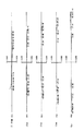
図1〜図5は本発明の後述する数値実施例1〜5のレンズ断面図である。図中、L1は正の屈折力の第1群,L2は負の屈折力の第2群,L3は正の屈折力の第3群である。
【0023】
第3群L3は正の屈折力の第31群L31、負の屈折力の第32群L32、そして正の屈折力の第33群L33の3つのレンズ群を有している。HGは保護ガラス、SPは開口絞り、FLは光学フィルター、FCはフレアーカット絞り、IPは像面である。
【0024】
無限遠物体から至近物体へのフォーカスは第2群を矢印LFの如く像面側へ移動させて行っている。光学系が振動したときの撮影画像のブレの補正(振動補償)は第32群L32を可動レンズ群(画像変位補正群)とし、矢印LTの如く光軸と直交する方向に移動させて行っている。
【0025】
本発明に係る光学系は第1群に対し、小レンズ径で、かつ軽量な負の屈折力の第2群を光軸上移動させることによってフォーカシングを行っているため、その駆動装置は低トルクで小型なものが利用できる。又、第2群を通過した光線は正の屈折力の第31群により収斂させており、これにより第32群(画像変位補正群)のレンズ径の小型化を容易にしている。更に正の屈折力の第33群を配置することにより、一定のレンズ全系の焦点距離を保ちつつ負の屈折力の第32群の屈折力を増大させて第32群の少ない偏心移動により結像面上の大きな像位置の変位(以後、偏心量と像位置変位の関係を像変位敏感度という。)を容易にしている。
【0026】
本実施形態では前述の如く各要素を設定することによって望遠光学系を備えたビデオカメラやスチルカメラ等の手持ち撮影時や不安定な三脚、一脚等に固定しての撮影等に生じる画像ブレを良好に補正している。
【0027】
本発明の防振機能を有したインナーフォーカス式の光学系は以上のように、物体側より順に正の屈折力の第1群,負の屈折力の第2群,そして正の屈折力の第3群の3つのレンズ群を有し、該第3群は正の屈折力の第31群、負の屈折力の第32群、そして正の屈折力の第33群の3つのレンズ群を有しており、該第2群を光軸上移動させてフォーカスを行い、該第32群を光軸と直交する方向に移動させて撮影画像の結像位置を変位させていることを基本構成としている。
【0028】
そして本発明のうち、第1発明では前述の条件式(a)を満足することを特徴としている。
【0029】
特に、第1発明として更に好ましくは前述の条件式(1)〜(3)を満足するようにしている。
【0030】
又、本発明のうち、第2発明では基本構成の基で前述の条件式(1)〜(3)を満足することを特徴としている。
【0031】
尚、以下、第1,第2発明を総称して『本発明』ともいう。
【0032】
第1発明に係る条件式(a)は、第1群と第2群の合焦の焦点距離f1‐2が全系の焦点距離fよりも10倍以上長くすること、即ち、第1群と第2群を通過した光束が略アフォーカルとなるようにする為のものである。
【0033】
これによって第1群と第2群による像点(第3群に対する物点)が第3群から十分遠くなるようにして、第2群,第3群の間隔のピント敏感度を小さくして、製作を容易にしている。
【0034】
特に、第3群には防振用のレンズ群が含まれており、防振機能が複雑になる傾向があるので、条件式(a)を満足させることによって第2群と第3群との組立精度を緩和させている。
【0035】
尚、条件式(a)の数値範囲は更に
|f1/f1‐2|<0.07
とするのが好ましい。
【0036】
そして第1発明と第2発明ではいずれも、各レンズ群の光学的諸定数を条件式(1),(2),(3)の如く設定している。これにより光学系全体の小型化を図りつつ、撮影画像のブレの補正を良好に行うと共に第32群の光軸と直交する方向の移動に伴う収差、即ち偏心に伴う偏心コマ収差、偏心非点収差、偏心像面湾曲等の偏心収差の発生を少なくし、又、物体距離全般にわたり良好なる光学性能を得ている。
【0037】
次に前述の条件式(1),(2),(3)の技術的意味について説明する。条件式(1)は正の屈折力の第1群の屈折力を適切に設定する為の条件である。条件式(1)の上限値を越えて第1群の屈折力が小さくなりすぎるとテレフォト系の作用が弱くなってくるため、レンズ全長が長くなってきて良くない。
【0038】
また、収斂作用が小さくなりすぎるため、第2群に入射する光束が太くなってしまい、第2群のレンズ径が大型化してしまう。他方、下限値を越えると正の屈折力が大きくなりすぎて高次の球面収差が発生してこれを他のレンズ群で補正することが困難になってくる。
【0039】
条件式(2)はフォーカス群である負の屈折力の第2群の屈折力と、正の屈折力の第1群の屈折力を適切に設定する為の条件である。条件式(2)の上限値を越えると正の屈折力の第1群で発生する諸収差、特に球面収差を負の屈折力の第2群で補正できなくなり、他方、下限値を越えると負の屈折力の第2群で球面収差が補正過剰になってしまうため、結果として光学系全体で良好なる光学性能を維持することが、困難となる。
【0040】
条件式(3)は正の屈折力の第3群の屈折力を適切に設定する為の条件である。条件式(3)の上限値を越えると、バックフォーカスが長くなりすぎるため、光学系全体の小型化が困難となったり、第1群で発生する正の歪曲収差の補正が困難となる。
【0041】
他方、下限値を越えると、球面収差やコマフレアー等を補正するために第3群のレンズ枚数が増えてしまい、結果として光学系全体の小型化が困難となったり、光学系全体での透過率が悪化するので良くない。
【0042】
第1,第2発明において、更に望ましくは、条件式(1)〜(3)の数値を以下の範囲とすると良い。
【0043】
0.3 < f1/f <0.5 ‥‥‥(1a)
0.25<|f2/f1|<0.55 ‥‥‥(2a)
0.25< f3/f <0.6 ‥‥‥(3a)
第1,第2発明によれば以上のようなレンズ構成をとることにより、光学系が振動したときの撮影画像のブレを補正しつつ、偏心収差変動を少なくし、又、物体距離全般にわたり良好なる光学性能を得ている。
【0044】
尚、第1,第2発明において更に防振の際の偏心収差変動を少なくし、又、物体距離全般にわたり良好なる光学性能を得るには次の諸条件のうち少なくとも1つを満足させるのが良い。
【0045】
(イ)前記第2群は2枚の負レンズと1枚の正レンズを有し、前記第31群,第32群,第33群の焦点距離を順にf31,f32,f33としたとき
0.05<|f 2/f|< 0.3 ‥‥‥(4)
0.1 < f31/f < 0.5 ‥‥‥(5)
0.05<|f32/f|< 0.2 ‥‥‥(6)
0.08< f33/f < 0.3 ‥‥‥(7)
を満足することである。
【0046】
本発明では第2群を少なくとも2枚の負レンズと、一枚の正レンズで構成することで諸収差を良好に維持することが容易となり、更に条件式(4)を満足することで第2群の屈折力を適切に設定して、第2群の比較的少ない移動量で、遠距離物体から近距離物体へのフォーカシングを行っている。
【0047】
条件式(5)〜(7)は第32群を光軸と略垂直方向に移動して結像位置の変位を行う際、大きな像変位敏感度を得つつも、良好な像性能を確保する為のものであり、この条件式(5)〜(7)の数値範囲を外れるとそのバランスを保つことが困難となってくる。
【0048】
本発明において、更に望ましくは条件式(4)〜(7)の数値を以下の範囲とするのが良い。
【0049】
0.1 <|f 2/f|< 0.25 ‥‥‥(4a)
0.15< f31/f < 0.35 ‥‥‥(5a)
0.07<|f32/f|< 0.18 ‥‥‥(6a)
0.1 < f33/f < 0.25 ‥‥‥(7a)
(ロ)第31群は第1,第2群により発生した残存収差を第32群以降のレンズ群にて補正を行い易くするために、軸上収差を補正しておくと良く、この為少なくとも一枚以上の正レンズ及び負レンズを有することが望ましい。
【0050】
(ハ)第32群が複数の負レンズと一枚以上の正レンズを有するのが良く、これによれば像変位時における色収差と諸収差の変動を抑えることが容易となる。
【0051】
(ニ)高い像変位敏感度の達成の為には、第33群はある程度強い正の屈折力を持たせるのが良い。特に大口径なレンズ系を達成しようとするならば、第33群は複数の正レンズを有すると良く、これにより特に高次の球面収差補正に有効となる。そして更に少なくとも1つの負レンズと正レンズを接合した正レンズや対面したレンズ面の曲率半径が近似した正,負レンズを含むようにすれば更なる色収差改善が期待できる。
【0052】
(ホ)第1群は複数の正レンズと一枚以上の負レンズで構成されるのが良く、高画質を得る為には物体側より正レンズ,正レンズ,両凹レンズ,物体側に凸面を向けた負のメニスカスレンズ、物体側が強い凸面である正レンズを有するの構成が良い。
【0053】
(ヘ)レンズ面の保護及び温度変化によるレンズ膨脹、収縮に伴う結像位置変化防止のためレンズ系の物体側に平面板ガラス又は透明部材又は弱い屈折力を有したレンズ(保護部材)を配置するのが良い。
【0054】
(ホ)光彩絞り(開口絞り)は小絞り時に使用画像範囲における周辺光束がケラレなければレンズ系のどの位置に配置しても良いが、フォーカス駆動機構と像変位レンズ群移動機構及び電気回路の基板実装等の配置スペース効率を考えたとき、第2群から第4群間の空気間中、または第3群内に配置するのが良い。
【0055】
(チ)光学フィルターは結像面と最も像面側のレンズ面間の空気間隔中に配置することがフィルター径の小型化とスペース効率上望ましい。
【0056】
(リ)固定絞りを結像面と最も像面側のレンズ面間の空気間隔中に配置するのが良い。これによれば像変位時における周辺光量の非対称性を軽減することができる。
【0057】
次に本発明の数値実施例を示す。数値実施例においてRiは物体側より順に第i番目のレンズ面の曲率半径、Diは物体側より第i番目のレンズ厚及び空気間隔、Niとνiは各々物体側より順に第i番目のレンズのガラスの屈折率とアッベ数である。数値実施例において最終の2つのレンズ面はフェースプレートやフィルター等のガラスブロックである。fは焦点距離、FnoはFナンバー、ωは半画角である。又前述の各条件式と数値実施例における諸数値との関係を表−1に示す。
【0058】
【外1】

【外2】
【外3】
【外4】
【外5】
【表1】
【発明の効果】
本発明によれば以上のように、光学系の一部のレンズ群を光軸と垂直な方向に偏心駆動させて撮影画像の変位(ブレ)を補正する際、各レンズ要素を適切に配置することによって各種の偏心収差を良好に補正し、又十分に少ない偏心駆動量で十分に大きい変位補正(ブレ補正)を実現することによって装置全体の小型化を可能とし、又インナーフォーカス式を採用しつつ、無限遠物体から近距離物体に至る広範囲の物体距離において、フォーカスの際の収差変動を良好に補正した防振機能を有したインナーフォーカス式の光学系を達成することができる。
【図面の簡単な説明】
【図1】本発明の数値実施例1のレンズ断面図
【図2】本発明の数値実施例2のレンズ断面図
【図3】本発明の数値実施例3のレンズ断面図
【図4】本発明の数値実施例4のレンズ断面図
【図5】本発明の数値実施例5のレンズ断面図
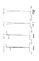
【図6】本発明の数値実施例1の基準状態(結像位置不変位)の縦収差図
【図7】本発明の数値実施例1の基準状態(結像位置不変位)の横収差図
【図8】本発明の数値実施例1において無限遠物体を0.5°の画角に相当する像位置変位を行ったときの横収差図
【図9】本発明の数値実施例2の基準状態(結像位置不変位)の縦収差図
【図10】本発明の数値実施例2の基準状態(結像位置不変位)の横収差図
【図11】本発明の数値実施例2において無限遠物体を0.5°の画角に相当する像位置変位を行ったときの横収差図
【図12】本発明の数値実施例3の基準状態(結像位置不変位)の縦収差図
【図13】本発明の数値実施例3の基準状態(結像位置不変位)の横収差図
【図14】本発明の数値実施例3において無限遠物体を0.5°の画角に相当する像位置変位を行ったときの横収差図
【図15】本発明の数値実施例4の基準状態(結像位置不変位)の縦収差図
【図16】本発明の数値実施例4の基準状態(結像位置不変位)の横収差図
【図17】本発明の数値実施例4において無限遠物体を0.5°の画角に相当する像位置変位を行ったときの横収差図
【図18】本発明の数値実施例5の基準状態(結像位置不変位)の縦収差図
【図19】本発明の数値実施例5の基準状態(結像位置不変位)の横収差図
【図20】本発明の数値実施例5において無限遠物体を0.5°の画角に相当する像位置変位を行ったときの横収差図
【符号の説明】
L1 第1群
L2 第2群
L3 第3群
L31 第31群
L32 第32群
L33 第33群
SP 開口絞り
S サジタル像面
M メリディオナル像面
d d線
g g線
FC フレアーカット絞り
FL 光学フィルター[0001]
BACKGROUND OF THE INVENTION
The present invention has a function of correcting a blur of a photographed image due to vibration of an optical system using an inner focus at the time of focusing, that is, a so-called anti-vibration function. The present invention relates to an inner focus type optical system having an anti-vibration function that prevents a decrease in optical performance when moved to exhibit an anti-vibration effect.
[0002]
[Prior art]
When shooting from a moving object such as a car or aircraft in progress, vibration is transmitted to the shooting system (shooting lens) and blur occurs in the shot image.
[0003]
In particular, when using an imaging system with a long focal length, it is difficult to suppress vibration of the imaging system. When the photographing system is tilted by vibration, the photographed image is displaced according to the tilt angle and the focal length of the photographing system. For this reason, there is a problem in the still image shooting device that the shooting time must be sufficiently shortened to prevent the deterioration of the image quality, and in the moving image shooting device, it is difficult to maintain the composition setting. There is a problem. Therefore, in such shooting, it is necessary to correct so that the displacement of the shot image does not cause blur of the shot image even when the shooting system is tilted by vibration.
[0004]
Conventionally, an anti-vibration optical system having a function of preventing blurring of a photographed image has been proposed in, for example, Japanese Patent Laid-Open Nos. 50-80147, 56-21133, 61-223819, and the like. Yes.
[0005]
In Japanese Patent Laid-Open No. 50-80147, in a zoom lens having two afocal variable magnification systems, the angular magnification of the first variable magnification system is M 1 and the angular magnification of the second variable magnification system is M 2. Scaling is performed in each zooming system so as to have a relationship of M 1 = 1-1 / M 2 , and the second zooming system is spatially fixed to correct image blur to stabilize the image. I am trying.
[0006]
In Japanese Examined Patent Publication No. 56-21133, in accordance with an output signal from a detecting means for detecting the vibration state of the optical device, some optical members are moved in a direction that cancels the vibrational displacement of the image due to vibration. Stabilization is planned.
[0007]
In JP-A-61-223819, in an imaging system in which a refractive variable apex angle prism is arranged closest to the subject, an image is obtained by changing the apex angle of the refractive variable apex angle prism in response to vibration of the imaging system. The image is stabilized by deflecting.
[0008]
Further, for example, Japanese Patent Laid-Open No. 50-80147 and Japanese Patent Laid-Open No. 56-223819 correct a blur of a photographed image by moving some lens groups in the optical system in a direction orthogonal to the optical axis. Etc. are proposed.
[0009]
On the other hand, there are various methods for focusing on the taking lens, and for example, the whole taking lens is moved or a part of the taking lens is moved. Among these, when the photographic lens is a telephoto lens having a long focal length, the photographic lens is large and heavy, and it is mechanically difficult to focus by moving the entire photographic lens.
[0010]
For this reason, many telephoto lenses focus by moving some lens groups. Among these, there are various types using an inner focus type in which focusing is performed by moving a part of the central lens group in a relatively small and lightweight lens system other than the front lens group of the photographing lens. Proposed.
[0011]
For example, Japanese Patent Laid-Open No. 55-147606 discloses an inner-focus telephoto lens having a focal length of 300 mm and F number of 2.8, and Japanese Patent Laid-Open Nos. 59-65820 and 59-65821 have a focal length of 135 mm. An inner focus telephoto lens with an F number of about 2.8 has been proposed.
[0012]
In each of the proposed inner focus telephoto lenses, there are three lenses in order from the object side: a first group having a positive refractive power, a second group having a negative refractive power, and a third group having a positive refractive power. And a second group is moved on the optical axis for focusing.
[0013]
[Problems to be solved by the invention]
In general, some lens groups in the shooting system are vibrated to eliminate blurring of the shot image, and a mechanism for obtaining a still image has a large amount of image blur correction and a lens group that vibrates for blur correction (movable lens group). ), And the entire optical system is required to be small. Also, when the movable lens group is decentered, if a large amount of decentration coma, decentered astigmatism, decentered chromatic aberration, decentration field curvature aberration, etc. occur, the image will be blurred due to decentration aberration when image blur is corrected. For example, when a large amount of decentration distortion occurs, the amount of movement of the image on the optical axis differs from the amount of movement of the peripheral image. For this reason, if the movable lens group is decentered to correct the image blur for the image on the optical axis, a phenomenon similar to the image blur occurs in the peripheral portion, which causes a significant deterioration in optical characteristics. come.
[0014]
In such an optical system having an anti-vibration function, when the movable lens group is moved in a direction orthogonal to the optical axis, or at the same time, is slightly rotated about one point on the optical axis as a rotation center, the image quality is improved. A so-called decentration sensitivity (small decentering aberration generation amount to reduce the decrease, and large image blur can be corrected with a small amount of movement or a small amount of rotation of the movable lens group to reduce the size of the entire apparatus. The ratio Δx / ΔH) of the image blur correction amount Δx with respect to the unit movement amount ΔH) is required to be large.
[0015]
As an optical system having an anti-vibration function, an optical system having an optical member that is spatially fixed with respect to vibration is difficult to support, and it is difficult to realize a compact optical system. Therefore, it is not suitable for the configuration of a small and light device. In addition, the optical system in which the variable apex angle prism is arranged on the most object side of the photographing system has an advantage that there is almost no aberration other than decentration chromatic aberration at the time of displacement correction. There is a drawback that it is difficult to easily correct the decentered chromatic aberration that occurs. In an optical system that decenters a part of the lens group of the photographing system, the apparatus can be reduced in size by appropriately selecting and arranging the lens group to be decentered. There has been a problem that it is difficult to realize sufficiently large displacement correction with a sufficiently small driving amount while satisfactorily correcting aberration, decentration astigmatism, decentration field curvature and the like.
[0016]
On the other hand, the inner focus type lens group for focusing is small and lightweight, so it is easy to operate and high-speed operation is possible, and the center of gravity of the entire lens system when focusing on an object at infinity and a close object is possible. There are advantages such as little change and easy holding.
[0017]
On the other hand, when the inner focus type is adopted in a telephoto lens having a bright F number, the aberration fluctuation at the time of focusing becomes large, and it is difficult to correct the aberration fluctuation at this time, which causes a decrease in optical performance. Yes.
[0018]
The present invention corrects displacement (blur) of a captured image by driving a part of a lens group in an optical system in a direction perpendicular to the optical axis to correct various decentering aberrations by appropriately disposing each lens element. It is possible to reduce the overall size of the device by realizing a sufficiently large displacement correction (blur correction) with a sufficiently small eccentric drive amount, and adopting an inner focus type, from an object at infinity It is an object of the present invention to provide an inner focus type optical system having an anti-vibration function that satisfactorily corrects aberration fluctuations during focusing over a wide range of object distances up to a close object.
[0019]
[Means for Solving the Problems]
The inner focus type optical system having the vibration isolating function of the invention of
In order from the object side, there are only three lens groups as a lens group: a first group having a positive refractive power, a second group having a negative refractive power, and a third group having a positive refractive power,
The second group has only two negative lenses and one positive lens as lenses,
The third group has only three lens groups as a lens group, that is, a positive refractive power group 31, a negative refractive power group 32, and a positive refractive power group 33.
The second group is moved on the optical axis to perform focusing, the thirty-second group is moved in a direction perpendicular to the optical axis, and the imaging position of the photographed image is displaced, and the focal length of the i-th group is set. fi,
The focal lengths of the thirty-first group, thirty-second group, and thirty-third group are sequentially set to f31, f32, f33,
When the focal length of the entire system is f ,
0.2 <f1 / f <0.6 (1)
0.1 <| f2 / f1 | <0.7 (2)
0.2 <f3 / f <0.8 (3)
0.05 <| f2 / f | <0.3 (4)
0.1 <f31 / f <0.5 (5)
0.05 <| f32 / f | <0.2 (6)
0.08 <f33 / f <0.3 (7)
It is characterized by satisfying the following conditions.
[0022]
DETAILED DESCRIPTION OF THE INVENTION
1 to 5 are lens cross-sectional views of numerical examples 1 to 5 to be described later of the present invention. In the figure, L1 is a first group having a positive refractive power, L2 is a second group having a negative refractive power, and L3 is a third group having a positive refractive power.
[0023]
The third lens unit L3 includes three lens units, ie, a positive lens unit 31 L31, a negative lens unit 32 L32, and a positive lens unit 33 L33. HG is a protective glass, SP is an aperture stop, FL is an optical filter, FC is a flare cut stop, and IP is an image plane.
[0024]
Focusing from an infinite object to a close object is performed by moving the second group to the image plane side as indicated by an arrow LF. The correction (vibration compensation) of the captured image when the optical system vibrates is performed by moving the thirty-second lens unit L32 as a movable lens group (image displacement correction group) and moving it in a direction perpendicular to the optical axis as indicated by an arrow LT. Yes.
[0025]
Since the optical system according to the present invention performs focusing by moving the second group having a small lens diameter and a light negative refractive power on the optical axis with respect to the first group, the driving device has a low torque. Small size can be used. The light beam that has passed through the second group is converged by the 31st group having a positive refractive power, thereby facilitating the reduction in the lens diameter of the 32nd group (image displacement correction group). Further, by arranging the 33rd group having a positive refractive power, the refractive power of the 32nd group having a negative refractive power is increased while maintaining a constant focal length of the entire lens system. Displacement of a large image position on the image plane (hereinafter, the relationship between the amount of eccentricity and image position displacement is referred to as image displacement sensitivity) is facilitated.
[0026]
In this embodiment, by setting each element as described above, image blurring that occurs during hand-held shooting such as a video camera or a still camera equipped with a telephoto optical system, or shooting that is fixed to an unstable tripod or monopod, etc. Is corrected well.
[0027]
As described above, the inner focus type optical system of the present invention has a first refractive power group, a negative second power group, and a positive refractive power first, in order from the object side. There are three lens groups of three groups, and the third group has three lens groups of a positive refractive power 31st group, a negative refractive power 32nd group, and a positive refractive power 33rd group. As a basic configuration, the second group is moved on the optical axis to perform focusing, and the thirty-second group is moved in a direction orthogonal to the optical axis to displace the imaging position of the photographed image. Yes.
[0028]
Among the present inventions, the first invention is characterized in that the conditional expression (a) described above is satisfied .
[0029]
In particular, the first invention preferably satisfies the above-mentioned conditional expressions (1) to (3).
[0030]
Of the present invention, the second invention is characterized in that the above-mentioned conditional expressions (1) to (3) are satisfied based on the basic configuration.
[0031]
Hereinafter, the first and second inventions are also collectively referred to as “the present invention”.
[0032]
Conditional expression (a) according to the first invention is that the focal length f1-2 of the focusing of the first group and the second group is longer than the focal length f of the entire system by 10 times or more. This is to make the light beam that has passed through the second group substantially afocal.
[0033]
As a result, the image point (object point for the third group) by the first group and the second group is sufficiently far from the third group, and the focus sensitivity of the distance between the second group and the third group is reduced. Making it easy.
[0034]
In particular, the third lens group includes a lens group for image stabilization, and the image stabilization function tends to be complicated. Therefore, by satisfying conditional expression (a), the second group and the third group are satisfied. Assembly accuracy is relaxed.
[0035]
The numerical range of conditional expression (a) is further | f1 / f1-2 | <0.07.
Is preferable.
[0036]
In both the first and second inventions, the optical constants of each lens group are set as conditional expressions (1), (2), and (3). As a result, while miniaturizing the entire optical system, the blur of the photographed image is corrected satisfactorily, and aberrations accompanying movement in the direction orthogonal to the optical axis of the 32nd group, that is, decentering coma and decentering astigmatism. Generation of decentration aberrations such as aberration and decentration field curvature is reduced, and good optical performance is obtained over the entire object distance.
[0037]
Next, the technical meaning of the conditional expressions (1), (2), and (3) will be described. Conditional expression (1) is a condition for appropriately setting the refractive power of the first group having a positive refractive power. If the refractive power of the first group becomes too small beyond the upper limit value of conditional expression (1), the telephoto system will be weakened, and the total lens length will become longer.
[0038]
Further, since the convergence effect becomes too small, the light beam incident on the second group becomes thick, and the lens diameter of the second group becomes large. On the other hand, if the lower limit is exceeded, the positive refractive power becomes too large and high-order spherical aberration occurs, making it difficult to correct this with other lens groups.
[0039]
Conditional expression (2) is a condition for appropriately setting the refractive power of the second group having negative refractive power, which is the focus group, and the refractive power of the first group having positive refractive power. If the upper limit value of conditional expression (2) is exceeded, various aberrations occurring in the first group with positive refractive power, particularly spherical aberration, cannot be corrected with the second group with negative refractive power, while negative values are exceeded when the lower limit value is exceeded. As a result, it becomes difficult to maintain good optical performance in the entire optical system.
[0040]
Conditional expression (3) is a condition for appropriately setting the refractive power of the third group having positive refractive power. If the upper limit value of conditional expression (3) is exceeded, the back focus becomes too long, making it difficult to reduce the size of the entire optical system or to correct positive distortion occurring in the first group.
[0041]
On the other hand, if the lower limit is exceeded, the number of lenses in the third group will increase in order to correct spherical aberration, coma flare, etc. As a result, it becomes difficult to downsize the entire optical system, or transmission through the entire optical system. It's not good because the rate gets worse.
[0042]
In the first and second inventions, it is more preferable that the numerical values of the conditional expressions (1) to (3) are in the following ranges.
[0043]
0.3 <f1 / f <0.5 (1a)
0.25 <| f2 / f1 | <0.55 (2a)
0.25 <f3 / f <0.6 (3a)
According to the first and second inventions, by adopting the lens configuration as described above, the fluctuation of the decentered aberration is reduced while correcting the blur of the photographed image when the optical system vibrates, and the entire object distance is good. Has obtained optical performance.
[0044]
In the first and second inventions, in order to further reduce fluctuations in decentration aberrations during image stabilization and to obtain good optical performance over the entire object distance, at least one of the following conditions must be satisfied. good.
[0045]
(A) The second group has two negative lenses and one positive lens, and the focal lengths of the thirty-first group, thirty-second group and thirty-third group are set to f31, f32 and f33 in order, respectively. 05 <| f2 / f | <0.3 (4)
0.1 <f31 / f <0.5 (5)
0.05 <| f32 / f | <0.2 (6)
0.08 <f33 / f <0.3 (7)
Is to satisfy.
[0046]
In the present invention, the second group is composed of at least two negative lenses and one positive lens, so that it is easy to maintain various aberrations satisfactorily, and further, the second conditional expression (4) is satisfied. The refractive power of the group is set appropriately, and focusing from a long-distance object to a short-distance object is performed with a relatively small amount of movement of the second group.
[0047]
Conditional expressions (5) to (7) ensure good image performance while obtaining a large image displacement sensitivity when moving the thirty-second lens group in a direction substantially perpendicular to the optical axis to move the image forming position. Therefore, it is difficult to maintain the balance when the numerical values of the conditional expressions (5) to (7) are out of the numerical range.
[0048]
In the present invention, it is more preferable that the numerical values of the conditional expressions (4) to (7) are in the following ranges.
[0049]
0.1 <| f2 / f | <0.25 (4a)
0.15 <f31 / f <0.35 (5a)
0.07 <| f32 / f | <0.18 (6a)
0.1 <f33 / f <0.25 (7a)
(B) In the 31st group, in order to make it easy to correct the residual aberration generated by the 1st and 2nd groups in the 32nd and subsequent lens groups, it is preferable to correct the axial aberration. It is desirable to have one or more positive and negative lenses.
[0050]
(C) The thirty-second lens group preferably includes a plurality of negative lenses and one or more positive lenses, which makes it easy to suppress variations in chromatic aberration and various aberrations when the image is displaced.
[0051]
(D) In order to achieve high image displacement sensitivity, the 33rd lens group should have a strong positive refractive power to some extent. In order to achieve a particularly large lens system, the 33rd group should have a plurality of positive lenses, which is particularly effective for correcting higher-order spherical aberration. Further chromatic aberration improvement can be expected by including a positive lens in which at least one negative lens and a positive lens are cemented, and a positive lens and a negative lens in which the radius of curvature of the facing lens surface is approximated.
[0052]
(E) The first group is preferably composed of a plurality of positive lenses and one or more negative lenses. In order to obtain high image quality, a positive lens, a positive lens, a biconcave lens, and a convex surface on the object side are provided from the object side. It is preferable to have a negative meniscus lens that faces and a positive lens that has a strong convex surface on the object side.
[0053]
(F) A flat plate glass or a transparent member or a lens (protective member) having a weak refractive power is disposed on the object side of the lens system in order to protect the lens surface and prevent a change in the imaging position due to the expansion and contraction of the lens due to temperature change. Is good.
[0054]
(E) The iris diaphragm (aperture diaphragm) may be arranged at any position in the lens system as long as the peripheral luminous flux in the image range used is not vignetted at the time of a small diaphragm, but the focus drive mechanism, the image displacement lens group moving mechanism, and the electric circuit When arrangement space efficiency such as board mounting is considered, it is preferable to arrange in the air between the second group and the fourth group or in the third group.
[0055]
(H) It is desirable for the optical filter to be disposed in the air space between the imaging surface and the lens surface closest to the image surface in terms of reduction in the filter diameter and space efficiency.
[0056]
(I) It is preferable to dispose the fixed stop in the air space between the image plane and the lens surface closest to the image plane. According to this, the asymmetry of the peripheral light amount at the time of image displacement can be reduced.
[0057]
Next, numerical examples of the present invention will be shown. In the numerical examples, Ri is the radius of curvature of the i-th lens surface in order from the object side, Di is the i-th lens thickness and air spacing from the object side, and Ni and νi are respectively the i-th lens in order from the object side. Refractive index and Abbe number of glass. In the numerical examples, the last two lens surfaces are glass blocks such as face plates and filters. f is a focal length, Fno is an F number, and ω is a half angle of view. Table 1 shows the relationship between the above-described conditional expressions and numerical values in the numerical examples.
[0058]
[Outside 1]
[Outside 2]
[Outside 3]
[Outside 4]
[Outside 5]
[Table 1]
【The invention's effect】
According to the present invention, as described above, when correcting a displacement (blur) of a captured image by driving a part of a lens group of an optical system in a direction perpendicular to the optical axis, each lens element is appropriately arranged. As a result, various types of decentration aberrations can be corrected satisfactorily, and a sufficiently large displacement correction (blur correction) can be achieved with a sufficiently small amount of decentering drive, enabling the overall size of the apparatus to be reduced, and an inner focus type is adopted. On the other hand, it is possible to achieve an inner focus type optical system having an anti-vibration function that satisfactorily corrects aberration fluctuations during focusing over a wide range of object distances from an infinite object to a close object.
[Brief description of the drawings]
1 is a lens cross-sectional view of Numerical Example 1 of the present invention. FIG. 2 is a lens cross-sectional view of Numerical Example 2 of the present invention. FIG. 3 is a lens cross-sectional view of Numerical Example 3 of the present invention. FIG. 5 is a lens cross-sectional view of Numerical Example 5 of the present invention. FIG. 6 is a longitudinal aberration diagram of a reference state (image position non-displacement) of Numerical Example 1 of the present invention. FIG. 7 is a lateral aberration diagram in the reference state (image position non-displacement) in Numerical Example 1 of the present invention. FIG. 8 is an object at infinity corresponding to an angle of view of 0.5 ° in Numerical Example 1 of the present invention. Fig. 9 is a lateral aberration diagram when the image position displacement is performed. Fig. 9 is a longitudinal aberration diagram in the reference state (image position non-displacement) of the
L1 1st group L2 2nd group L3 3rd group L31 31st group L32 32nd group L33 33rd group SP Aperture stop S Sagittal image plane M Meridional image plane d d-line g g-line FC Flare cut stop FL Optical filter
Claims (4)
第2群は2枚の負レンズと1枚の正レンズのみをレンズとして有し、
該第3群は正の屈折力の第31群、負の屈折力の第32群、そして正の屈折力の第33群の3つのレンズ群のみをレンズ群として有しており、
該第2群を光軸上移動させてフォーカスを行い、該第32群を光軸と直交する方向に移動させて撮影画像の結像位置を変位させており、該第i群の焦点距離をfi、
該第31群,第32群,第33群の焦点距離を順にf31,f32,f33、
全系の焦点距離をfとしたとき、
0.2< f1/f <0.6
0.1<|f2/f1|<0.7
0.2< f3/f <0.8
0.05<|f 2/f|< 0.3
0.1 < f31/f < 0.5
0.05<|f32/f|< 0.2
0.08< f33/f < 0.3
なる条件を満足することを特徴とする防振機能を有したインナーフォーカス式の光学系。In order from the object side, there are only three lens groups of a positive refractive power first group, a negative refractive power second group, and a positive refractive power third group as a lens group,
The second group has only two negative lenses and one positive lens as lenses,
Third group has 31 unit of positive refractive power, negative 32nd group refractive power, and only positive three lens groups of the 33 group refractive power as a lens,
The second group is moved on the optical axis to perform focusing, the thirty-second group is moved in a direction orthogonal to the optical axis to displace the imaging position of the photographed image, and the focal length of the i-th group is set. fi,
The focal lengths of the thirty-first group, thirty-second group, and thirty-third group are sequentially set to f31, f32, f33,
When the focal length of the entire system is f ,
0.2 <f1 / f <0.6
0.1 <| f2 / f1 | <0.7
0.2 <f3 / f <0.8
0.05 <| f2 / f | <0.3
0.1 <f31 / f <0.5
0.05 <| f32 / f | <0.2
0.08 <f33 / f <0.3
An inner focus type optical system having an anti-vibration function characterized by satisfying the following conditions.
Priority Applications (2)
| Application Number | Priority Date | Filing Date | Title |
|---|---|---|---|
| JP34585997A JP3745104B2 (en) | 1997-12-01 | 1997-12-01 | Inner focus optical system with anti-vibration function |
| US09/172,164 US6115188A (en) | 1997-10-16 | 1998-10-14 | Optical system and optical apparatus having the same |
Applications Claiming Priority (1)
| Application Number | Priority Date | Filing Date | Title |
|---|---|---|---|
| JP34585997A JP3745104B2 (en) | 1997-12-01 | 1997-12-01 | Inner focus optical system with anti-vibration function |
Publications (2)
| Publication Number | Publication Date |
|---|---|
| JPH11160617A JPH11160617A (en) | 1999-06-18 |
| JP3745104B2 true JP3745104B2 (en) | 2006-02-15 |
Family
ID=18379482
Family Applications (1)
| Application Number | Title | Priority Date | Filing Date |
|---|---|---|---|
| JP34585997A Expired - Fee Related JP3745104B2 (en) | 1997-10-16 | 1997-12-01 | Inner focus optical system with anti-vibration function |
Country Status (1)
| Country | Link |
|---|---|
| JP (1) | JP3745104B2 (en) |
Cited By (1)
| Publication number | Priority date | Publication date | Assignee | Title |
|---|---|---|---|---|
| US8699151B2 (en) | 2011-05-17 | 2014-04-15 | Tamron Co., Ltd. | Imaging lens |
Families Citing this family (15)
| Publication number | Priority date | Publication date | Assignee | Title |
|---|---|---|---|---|
| JP3505099B2 (en) * | 1999-02-04 | 2004-03-08 | ペンタックス株式会社 | Medium telephoto lens |
| JP4652539B2 (en) * | 2000-08-31 | 2011-03-16 | キヤノン株式会社 | Imaging optical system and optical apparatus using the same |
| JP4639635B2 (en) | 2004-05-07 | 2011-02-23 | 株式会社ニコン | A telephoto lens with a large aperture ratio |
| JP5101878B2 (en) | 2006-12-28 | 2012-12-19 | 富士フイルム株式会社 | telescope lens |
| JP5582905B2 (en) | 2010-07-27 | 2014-09-03 | オリンパスイメージング株式会社 | Imaging optical system and imaging apparatus using the same |
| JP5429244B2 (en) * | 2011-06-27 | 2014-02-26 | 株式会社ニコン | Optical system, optical device |
| US8941921B2 (en) | 2010-08-30 | 2015-01-27 | Nikon Corporation | Optical system, optical apparatus, and method for manufacturing optical system |
| JP5867294B2 (en) * | 2012-05-30 | 2016-02-24 | 株式会社ニコン | PHOTOGRAPHIC LENS, OPTICAL DEVICE, AND MANUFACTURING METHOD |
| KR101941249B1 (en) | 2013-04-08 | 2019-01-22 | 삼성전자주식회사 | Telephoto lens and photographing apparatus having the same |
| JP6361088B2 (en) * | 2013-04-17 | 2018-07-25 | 株式会社ニコン | PHOTOGRAPHIC LENS, OPTICAL DEVICE, AND MANUFACTURING METHOD FOR PHOTOGRAPHIC LENS |
| JP2015108811A (en) | 2013-10-22 | 2015-06-11 | オリンパス株式会社 | Single focal length lens system and image capturing device having the same |
| JP2015108814A (en) | 2013-10-23 | 2015-06-11 | オリンパス株式会社 | Single focal length lens system and image capturing device having the same |
| JP6440450B2 (en) | 2013-11-08 | 2018-12-19 | オリンパス株式会社 | Imaging lens system and imaging apparatus including the same |
| JP2015121771A (en) * | 2013-11-20 | 2015-07-02 | オリンパス株式会社 | Single focal length lens system and imaging device with same |
| JP2015102810A (en) | 2013-11-27 | 2015-06-04 | オリンパス株式会社 | Image formation lens system and imaging device including the same |
-
1997
- 1997-12-01 JP JP34585997A patent/JP3745104B2/en not_active Expired - Fee Related
Cited By (1)
| Publication number | Priority date | Publication date | Assignee | Title |
|---|---|---|---|---|
| US8699151B2 (en) | 2011-05-17 | 2014-04-15 | Tamron Co., Ltd. | Imaging lens |
Also Published As
| Publication number | Publication date |
|---|---|
| JPH11160617A (en) | 1999-06-18 |
Similar Documents
| Publication | Publication Date | Title |
|---|---|---|
| JP5064837B2 (en) | Zoom lens with anti-vibration function | |
| JP3486541B2 (en) | Inner focus optical system having vibration proof function and camera having the same | |
| JP3564061B2 (en) | Zoom lens and optical device using the same | |
| JP4046834B2 (en) | Variable magnification optical system with anti-vibration function | |
| JP4630423B2 (en) | Zoom lens and optical apparatus using the same | |
| JP4672880B2 (en) | Variable magnification optical system and optical apparatus using the same | |
| JP3072815B2 (en) | Variable power optical system | |
| JPH06265826A (en) | Compact zoom lens with vibration proof function | |
| JP3745104B2 (en) | Inner focus optical system with anti-vibration function | |
| JP3814406B2 (en) | Variable magnification optical system having anti-vibration function and camera having the same | |
| JP3919580B2 (en) | Zoom lens and optical apparatus having the same | |
| JP2007033553A (en) | Zoom lens and imaging apparatus having the same | |
| JPH1152245A (en) | Zoom lens having vibration compensating function | |
| JP4323584B2 (en) | Variable magnification optical system with anti-vibration function | |
| JP4545849B2 (en) | Variable magnification optical system | |
| JP4227223B2 (en) | Zoom lens | |
| JP4401469B2 (en) | Zoom lens | |
| JP5361496B2 (en) | Zoom lens and imaging apparatus having the same | |
| JP4109896B2 (en) | Variable magnification optical system having anti-vibration function and imaging apparatus using the same | |
| JP4829445B2 (en) | Zoom lens and optical apparatus having the same | |
| JP4109854B2 (en) | Zoom lens and optical apparatus having the same | |
| JP4272725B2 (en) | Optical system | |
| JP4095131B2 (en) | Variable magnification optical system having anti-vibration function and imaging apparatus having the same | |
| JP4324175B2 (en) | Variable magnification optical system with anti-vibration function | |
| JP3927684B2 (en) | Variable magnification optical system with anti-vibration function |
Legal Events
| Date | Code | Title | Description |
|---|---|---|---|
| A521 | Written amendment |
Free format text: JAPANESE INTERMEDIATE CODE: A523 Effective date: 20040322 |
|
| A621 | Written request for application examination |
Free format text: JAPANESE INTERMEDIATE CODE: A621 Effective date: 20040322 |
|
| A977 | Report on retrieval |
Free format text: JAPANESE INTERMEDIATE CODE: A971007 Effective date: 20050706 |
|
| A131 | Notification of reasons for refusal |
Free format text: JAPANESE INTERMEDIATE CODE: A131 Effective date: 20050712 |
|
| A521 | Written amendment |
Free format text: JAPANESE INTERMEDIATE CODE: A523 Effective date: 20050912 |
|
| TRDD | Decision of grant or rejection written | ||
| A01 | Written decision to grant a patent or to grant a registration (utility model) |
Free format text: JAPANESE INTERMEDIATE CODE: A01 Effective date: 20051115 |
|
| A61 | First payment of annual fees (during grant procedure) |
Free format text: JAPANESE INTERMEDIATE CODE: A61 Effective date: 20051116 |
|
| R150 | Certificate of patent or registration of utility model |
Free format text: JAPANESE INTERMEDIATE CODE: R150 |
|
| FPAY | Renewal fee payment (event date is renewal date of database) |
Free format text: PAYMENT UNTIL: 20091202 Year of fee payment: 4 |
|
| FPAY | Renewal fee payment (event date is renewal date of database) |
Free format text: PAYMENT UNTIL: 20091202 Year of fee payment: 4 |
|
| FPAY | Renewal fee payment (event date is renewal date of database) |
Free format text: PAYMENT UNTIL: 20101202 Year of fee payment: 5 |
|
| FPAY | Renewal fee payment (event date is renewal date of database) |
Free format text: PAYMENT UNTIL: 20111202 Year of fee payment: 6 |
|
| FPAY | Renewal fee payment (event date is renewal date of database) |
Free format text: PAYMENT UNTIL: 20121202 Year of fee payment: 7 |
|
| FPAY | Renewal fee payment (event date is renewal date of database) |
Free format text: PAYMENT UNTIL: 20131202 Year of fee payment: 8 |
|
| LAPS | Cancellation because of no payment of annual fees |