US7057831B2 - Optical system - Google Patents
Optical system Download PDFInfo
- Publication number
- US7057831B2 US7057831B2 US11/045,742 US4574205A US7057831B2 US 7057831 B2 US7057831 B2 US 7057831B2 US 4574205 A US4574205 A US 4574205A US 7057831 B2 US7057831 B2 US 7057831B2
- Authority
- US
- United States
- Prior art keywords
- optical system
- optical
- refractive
- optical element
- point
- Prior art date
- Legal status (The legal status is an assumption and is not a legal conclusion. Google has not performed a legal analysis and makes no representation as to the accuracy of the status listed.)
- Expired - Fee Related, expires
Links
Images


Classifications
-
- G—PHYSICS
- G02—OPTICS
- G02B—OPTICAL ELEMENTS, SYSTEMS OR APPARATUS
- G02B13/00—Optical objectives specially designed for the purposes specified below
- G02B13/02—Telephoto objectives, i.e. systems of the type + - in which the distance from the front vertex to the image plane is less than the equivalent focal length
-
- G—PHYSICS
- G02—OPTICS
- G02B—OPTICAL ELEMENTS, SYSTEMS OR APPARATUS
- G02B27/00—Optical systems or apparatus not provided for by any of the groups G02B1/00 - G02B26/00, G02B30/00
- G02B27/0025—Optical systems or apparatus not provided for by any of the groups G02B1/00 - G02B26/00, G02B30/00 for optical correction, e.g. distorsion, aberration
Definitions
- the present invention relates to an optical system, which is suitable for optical apparatuses such as cameras for silver-haloid films, digital still cameras, video cameras, telescopes, binoculars, and projectors.
- optical performance thereof tends to be decreased by increase of various aberrations, especially longitudinal chromatic aberration, chromatic aberration of magnification and the like, with shortening the total lens length (total optical length; the length from a first lens surface on an object side to an image plane) for attempting the miniaturization of the entire optical system.
- total optical length total optical length; the length from a first lens surface on an object side to an image plane
- lengthening its focal length increases chromatic aberrations.
- a lens unit that is located on the front side of a pupil, where passing heights of a paraxial marginal ray and a paraxial chief ray from the optical axis become relatively large is constituted by a lens having a positive refractive power, which is formed of a low dispersion optical material with anomalous partial dispersion such as fluorite, and a lens having a negative refractive power, which is formed of a high dispersion optical material to reduce the chromatic aberrations.
- Such various telephoto type optical systems have been proposed (see Patent Documents 1 to 3).
- the absolute value of a numerical value corresponding to Abbe's number of a diffraction optical element is a small number of 3.45. Therefore, the diffraction optical element is characterized in that the slight change of its power (a power is the reciprocal of its focal length) by diffraction causes the great change of the chromatic aberrations with little impact on spherical aberration, coma aberration, astigmatism or the like. Moreover, the power changes linearly for the change of wavelength of incident light because the light treated is diffraction light. Thereby, the wavelength characteristic of chromatic aberration coefficients forms a complete straight line.
- the optical system can be designed only by optimizing grass materials and power of constituent lenses so that linearity of the wavelength characteristic of chromatic aberration coefficients may be obtained, without a consideration for the absolute amount of the chromatic aberration deteriorating due to the total length shortening. As a result, an optical system of the telephoto type whose total lens length is shortened can be obtained.
- a liquid material with comparatively high dispersion and a property like anomalous partial dispersion, is known as an optical material having a chromatic aberration correction action that is similar to a diffraction optical element, an optical system with the liquid material having been proposed (see Patent Document 6).
- the diffraction optical element has an enough correction action for the chromatic aberration, it generates diffraction light of unnecessary diffraction order other than diffraction light of a designed diffraction order that is actually used.
- the unnecessary diffraction light becomes colored flare light deteriorating the image formation performance of the optical system.
- Patent Document 6 Since the material disclosed in Patent Document 6 is a liquid material, the structure to seal it is needed. Therefore, the use of the material makes the manufacture of the optical system difficult. Moreover, since there is a problem of the change of characteristics such as a refractive index and dispersion by temperature, too, it cannot be said that the environment resistance of the material is enough. In addition, there is a fault that the sufficient correction action of the chromatic aberration is hard to obtain because an interface with air cannot be formed, in addition to a comparatively large Abbe's number and comparatively small anomalous partial dispersion.
- the present invention was made based on the above-mentioned problems of the conventional examples, and it is an object of the present invention is to provide an optical system, which can excellently correct various aberrations such as chromatic aberration, and can be manufactured easily, and has an excellent environment resistance.
- An exemplified optical system of the present invention is a so-called an optical system of a telephoto type, in which its total lens length is shorter than its focal length.
- the optical system comprises a refractive optical element having refractive surfaces on a light-incident side and a light-emergent side, the refractive optical element being made of a solid material that satisfies the following conditions: ⁇ d ⁇ 30 ⁇ gd ⁇ 3.333 ⁇ 10 ⁇ 3 ⁇ d+ 1.40 ⁇ gF ⁇ 2.615 ⁇ 10 ⁇ 3 ⁇ d+ 0.67
- ⁇ d represents an Abbe's number
- ⁇ gd and ⁇ gF represent partial dispersion ratios
- the optical system is characterized in that, the refractive optical element has a negative optical power in a case where the refractive optical element is located on a front side (an object side or magnifying side) of a pupil position, and the refractive optical element has a positive optical power in a case where the refractive optical element is located on a rear side (an image side or demagnifying side) of the pupil position.
- ⁇ d ( Nd ⁇ 1)/( NF ⁇ NC )
- ⁇ gd ( Ng ⁇ Nd )/( NF ⁇ NC )
- ⁇ gF ( Ng ⁇ NF )/( NF ⁇ NC ).
- refractive indexes for the g-line, F-line, d-line and C-line are represented by Ng, NF, Nd and NC, respectively.
- a solid material in the present invention indicates a material that is solid in a state in which the optical system is used, not indicating that it is solid before the optical system is used, such as a manufacturing process. For instance, even if the material was liquid when manufacturing, a material cured from the liquid material is also included in the solid material of the present invention.
- FIG. 1 is a schematic view showing a paraxial arrangement for explaining optical actions of an optical system in the present invention.
- FIG. 2 is a sectional view showing an optical system of Numerical Embodiment 1 in the present invention.
- FIG. 3 shows aberration charts of the optical system of Numerical Embodiment 1 in in-focus state on an infinite object.
- FIG. 4 is a sectional view showing an optical system of Numerical Embodiment 2 in the present invention.
- FIG. 5 shows aberration charts of the optical system of Numerical Embodiment 2 in in-focus state on an infinite object.
- FIG. 6 is a schematic view for explaining the features of the dispersion characteristic of ITO.
- FIG. 7 is a schematic view showing substantial parts of an image-taking apparatus with the optical system of the present invention.
- the optical system of the present invention is used for image-taking apparatuses such as digital cameras, video cameras and silver-haloid film cameras, optical apparatuses such as an observation apparatus such as a telescope and binoculars, copiers, and projectors.
- the optical system of the present invention is characterized in adopting a telephoto type (optical system whose total lens length is shorter than its focal length), and giving a refraction action to a solid material with high dispersion and a low partial dispersion ratio.
- the solid material with high dispersion and a low partial dispersion ratio which is used in the present invention, indicates a material that is solid in a state in which the optical system is used; it may be in any states before the optical system is used, such as a manufacturing process. For instance, even if the material was liquid when manufacturing, a material cured from the liquid material is also included in the solid material of the present invention.
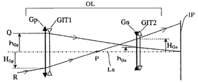
- FIG. 1 is a schematic view showing a paraxial arrangement for explaining optical actions of the optical system in the present invention.
- the reference character OL denotes an optical system of a telephoto type whose total lens length (distance from a first lens surface to an image plane) is shorter than its focal length.
- the reference characters Gp and Gn denote a front unit with a positive refractive power (the optical power is the reciprocal of its focal length) and a rear unit with a negative refractive power, respectively, the units constituting the telephoto type optical system OL.
- the reference characters GIT 1 and GIT 2 denote refractive optical elements GIT made of a material that satisfies the following conditional expressions (1) to (3), which are introduced into the front unit Gn and rear unit Gp, respectively.
- each of all lenses constituting the front unit Gn and rear unit Gp is a thin single lens, and the lenses are arranged on an optical axis in the front unit Gn and rear unit Gp, respectively, with a distance of 0.
- each of the refractive optical elements GIT 1 and GIT 2 is also a thin single lens, and they are arranged on the optical axis La in the front unit Gn and rear unit Gp, respectively, with a distance of 0.
- the reference character Q denotes a paraxial marginal ray
- the reference character R denotes a paraxial chief ray
- the reference character P denotes a crossing point where the paraxial chief ray R crosses the optical axis La, the point P corresponding a pupil center (for instance, the center of an aperture stop).
- the reference character IP denotes an image plane.
- the “paraxial marginal ray” is a paraxial ray generated when the light having a height of 1 from the optical axis of the optical system enters the optical system, parallel to the optical axis, in a case where the focal length of the entire optical system is normalized to 1.
- an object is located at the left of the optical system in the figure, and a ray enters the optical system from the object side progresses from the left to the right.
- the “paraxial chief ray” is a paraxial ray that passes through the crossing point of the entrance pupil of the optical system and the optical axis, among the rays that enter with an angle of ⁇ 45 degrees to the optical axis, in a case where the focal length of the entire optical system is normalized to 1.
- the clockwise direction measured from the optical axis is positive, and the anti-clockwise direction is negative.
- the left side corresponds to the front side an object side for an image-taking optical system or the like, and a magnifying side (a screen side) for a projection optical system of a liquid crystal projector or the like), and the right side corresponds to the rear side (an image side for the image-taking optical system or the like, and a demagnifying side (an original image side) for the projection optical system of the liquid crystal projector or the like).
- the optical system OL shown in FIG. 1 is an optical system in which the maximum value h Gp of height from the optical axis La of a passing point of the paraxial marginal ray Q on a lens surface that is located on the front side of the point P where the paraxial chief ray R crosses the optical axis La, is larger than the maximum value h Gn of height from the optical axis La of a passing point of the paraxial marginal ray Q on a lens surface that is located on the demagnifying side (image side) of the point P.
- Abbe's numbers of the solid material used for the optical members in the present invention are as follows.
- the optical system of the present invention comprises at least one refractive optical element GIT made of a solid material that its Abbe's number ⁇ d and partial dispersion ratios ⁇ gd and ⁇ gF satisfy the following conditions: ⁇ d ⁇ 30 (1) ⁇ gd ⁇ 3.333 ⁇ 10 ⁇ 3 ⁇ d +1.40 (2) ⁇ gF ⁇ 2.615 ⁇ 0 ⁇ 3 ⁇ d+ 0.67. (3)
- the solid materials that satisfy the conditional expressions (1) to (3) include a material made of Indium-Tin Oxide (ITO), for example.
- ITO Indium-Tin Oxide
- the optical system in FIG. 1 is characterized by the following (A) and (B).
- the refractive optical element GIT has a negative refractive power in a case where the refractive optical element GIT is located on the front side (the object side or the magnifying side) of the point P.
- the refractive optical element GIT has a positive refractive power in a case where the refractive optical element GIT is located on the rear side (the image side or the demagnifying side) of the point P.
- the refractive power of the refractive optical element GIT is shown by the refractive power when both two refractive surfaces that constitute the refractive optical element GIT face air (a medium with a refractive power of 1).
- using the refractive optical element GIT in at least one of the front unit Gn and the rear unit Gp makes possible obtaining an optical system suitable for the object of the present invention.
- each change of the aberration coefficients ⁇ L and ⁇ T for the refractive power change ⁇ of the lens surface increases with decreasing the absolute value of Abbe's number ⁇ (that is, increasing the dispersion). Therefore, using a high dispersion material with a small absolute value of Abbe's number ⁇ makes the amount of the refractive power change ⁇ for obtaining a required chromatic aberration small. This means that the chromatic aberration can be controlled without a large impact on spherical aberration, coma aberration and astigmatism or the like in the aberration theory, and thereby the independence of the chromatic aberration correction rises.
- a lens surface of at least one lens among the lenses constituting the optical system is a refractive lens surface formed of a high dispersion material.
- the refractive index on a short wavelength side is higher (Abbe's number is a positive value) than that on a long wavelength side, and a dispersion characteristic curve has a shape that is convex downward (that is, the value of the partial dispersion ratio is positive), the change of refractive index for the change of wavelength increasing with shortening the wavelength.
- the higher dispersion of the optical material with a smaller Abbe's number increases its partial dispersion ratio, and thereby the dispersion characteristic curve has a stronger tendency to be convex downward.
- the wavelength dependence characteristic curve of chromatic aberration coefficients on the lens surface made of the material shows a larger curvature on the short wavelength side, compared with a case where a material with a small partial dispersion ratio is used.
- the change of the chromatic aberration coefficient for controlling the chromatic aberration causes the rotational change of the entire inclination of the wavelength dependence characteristic curve of chromatic aberration coefficients around a position of a design standard wavelength.
- the chromatic aberration of the entire system is corrected by canceling comparatively large chromatic aberration coefficients mutually between the refractive optical system portion GIT and the refractive optical system portion G.
- a material of a positive lens constituting the refractive optical system portion G that has a comparatively high dispersion is selected, and a material of a negative lens constituting the refractive optical system portion G that has a comparatively low dispersion is selected.
- the refractive optical system portion GIT is provided with an adequate refractive power to cancel the entire inclination of the wavelength dependence characteristic curve of chromatic aberration coefficients of the refractive optical system portion G.
- the refractive optical system portion GIT is formed by an optical material with a large partial dispersion ratio, since the wavelength dependence characteristic curve of chromatic aberration coefficients of the refractive optical system portion GIT has a larger curvature than that of the refractive optical system portion G in the opposite direction, a component of the curvature cannot be canceled though a component of the entire inclination can be canceled.
- the refractive optical system portion GIT is formed by an optical material with a small partial dispersion ratio
- the wavelength dependence characteristic curve of chromatic aberration coefficients of the refractive optical system portion GIT has linearity comparatively, the inclination can be changed rotationally around the position of the design wavelength while maintaining the linearity comparatively even if the refractive power is changed to control the chromatic aberration. Therefore, the inclination component and the curvature component of the wavelength dependence characteristic curve of chromatic aberration coefficients can be canceled at the same time comparatively easily by using the refractive optical system portion GIT and refractive optical system portion G.
- the material of the refractive optical system portion GIT is an optical material with a low partial dispersion ratio as well as high dispersion.
- the refractive optical element used in the optical system of the present invention satisfies the conditional expressions (1), (2) and (3), these conditional expressions showing the relation between Abbe's numbers and partial dispersion ratios for correcting the chromatic aberration excellently, based on the principle explained above.
- the above-mentioned Abbe's number ⁇ d is the Abbe's number of the refractive optical system portion (lens or layer) GIT.
- the above-mentioned partial dispersion ratios ⁇ gd and ⁇ gF are the partial dispersion ratios of the refractive optical system portion (lens or layer) GIT.
- a material of the refractive optical element used in the optical system does not satisfy at least one of the above-mentioned conditional expressions (1) to (3) because an excellent correction of the chromatic aberration in the entire optical system becomes difficult.
- the numerical range can be set to the following range. ⁇ d ⁇ 18 (1b)
- the numerical range can be set to the following range. ⁇ d ⁇ 16 (1c)
- the numerical range can be set to the following range. ⁇ d ⁇ 14 (1d)
- the numerical ranges of the conditional expressions (2) and (3) to the following ranges, based on satisfying one of the conditional expressions (1), (1a), (1b), (1c) and (1d), gives a more excellent optical performance.
- the numerical ranges can be set to the following ranges. ⁇ gd ⁇ 3.333 ⁇ 10 ⁇ 3 ⁇ d+ 1.25 (2b) ⁇ gF ⁇ 2.615 ⁇ 10 ⁇ 3 ⁇ d+ 0.56 (3b)
- the numerical ranges can be set to the following ranges. ⁇ gd ⁇ 3.333 ⁇ 10 ⁇ 3 ⁇ d+ 1.2375 (2c) ⁇ gF ⁇ 2.615 ⁇ 10 ⁇ 3 ⁇ d+ 0.55 (3c)
- the numerical ranges can be set to the following ranges. ⁇ gd ⁇ 1.1137 (2d) ⁇ gF ⁇ 0.47 (3d)
- the wavelength dependence characteristic of the longitudinal chromatic aberration coefficient of the front unit Gp which is the first term in the expression (c) of the wavelength dependence characteristic of the longitudinal chromatic aberration coefficient L( ⁇ )
- the wavelength dependence characteristic of longitudinal chromatic aberration coefficients of the rear unit Gn which is the second term in the expression (c)
- the wavelength dependence characteristic of longitudinal chromatic aberration coefficients L( ⁇ ) of the entire optical system has a negative entire inclination and a tendency to be convex upward because the characteristic of the front unit Gp slightly remains.
- the refractive power of the refractive optical element GIT is represented by ⁇ GIT ( ⁇ 0 )
- the height of the paraxial marginal ray that makes incident on the refractive optical element GIT is represented by h GIT ( ⁇ 0 )
- ⁇ GIT ( ⁇ ) ⁇ N GIT ( ⁇ 0 ) ⁇ 1 ⁇ / ⁇ N GIT ( ⁇ ) ⁇ N GIT ( ⁇ 0 ) ⁇ .
- the wavelength dependence characteristic of longitudinal chromatic aberration coefficients of the refractive optical element GIT becomes a curve which has a negative entire inclination and is gently convex downward when ⁇ GIT ( ⁇ 0 )°0, and becomes a curve which has a positive entire inclination and is gently convex upward when ⁇ GIT ( ⁇ 0 ) ⁇ 0.
- the entire inclination that has been shifted greatly by the change of the grass material can be corrected only by changing the refractive power ⁇ GIT ( ⁇ 0 ) of the refractive optical element GIT in the negative direction again.
- the wavelength dependence characteristic of the longitudinal chromatic aberration coefficient in which both the entire inclination component and the curvature component have been corrected excellently, can be obtained.
- the introducing location in the optical system of the refractive optical element GIT is preferable to be in the front unit Gp where the refractive power of the refractive optical element GIT becomes comparatively small, and the change amount of the refractive power at the time of the chromatic aberration correction is comparatively small.
- the refractive optical element GIT can have a wavelength dependence characteristic curve of the longitudinal chromatic aberration coefficient with comparatively high linearity.
- the curvature component that is convex upward in the wavelength dependence characteristic curve of longitudinal chromatic aberration coefficients, which is increased by the refractive optical element GIT, can decrease, including the time of the chromatic aberration correction.
- the wavelength dependence characteristic curve of the longitudinal chromatic aberration coefficient of the entire system besides the refractive optical element GIT can become a curve convex downward comparatively easily, without being given a large negative inclination.
- the wavelength dependence characteristic of chromatic aberration of magnification coefficients of the front unit Gp which is the first term in the expression (d) of the wavelength dependence characteristic of chromatic aberration of magnification coefficients T( ⁇ )
- the wavelength dependence characteristic of chromatic aberration of magnification coefficients of the rear unit Gn which is the second term in the expression (d)
- the wavelength dependence characteristic of chromatic aberration of magnification coefficients T( ⁇ ) of the entire optical system has a positive entire inclination and a tendency to be convex downward because the characteristic of the front unit Gp slightly remains.
- the wavelength dependence characteristic curve of chromatic aberration of magnification coefficients of the entire system besides the refractive optical element GIT becomes a curve which is convex upward and has a large positive inclination, and the curvature component thereof is canceled at the same time by selecting a grass material with higher dispersion (that is, the curvature of the dispersion characteristic is larger) as the material of the positive lens constituting the front unit Gp and a grass material with lower dispersion (that is, the curvature of the dispersion characteristic is smaller) as the material of the negative lens constituting the front unit Gp when correcting the longitudinal chromatic aberration, as mentioned above.
- the entire inclination that has shifted greatly by the change of the grass material is also corrected by changing the refractive power ⁇ GIT ( ⁇ 0 ) of the refractive optical element GIT in the negative direction again when correcting the longitudinal chromatic aberration, as mentioned above.
- the longitudinal chromatic aberration and chromatic aberration of magnification can be corrected at the same time by giving a negative refractive power to the refractive optical element GIT and introducing it into the front unit Gp with a positive refractive power.
- L GIT ( ⁇ ) h Gn 2 ( ⁇ 0 ) ⁇ GIT ( ⁇ 0 )/ ⁇ GIT ( ⁇ )
- T GIT ( ⁇ ) h Gn 2 ( ⁇ 0 ) ⁇ GIT ( ⁇ 0 )/ ⁇ GIT ( ⁇ ).
- introducing the refractive optical element GIT into the rear unit Gn in the optical system of the telephoto type contributes to the chromatic aberration of magnification more than to the longitudinal chromatic aberration.
- the curvature component can be corrected easily by the selection of the grass material for the front unit Gp, as mentioned above.
- the maximum height h Gp max from the optical axis of a passing point of the paraxial marginal ray Q on a lens surface that is located on the front side of the point P is larger than the maximum height h Gn max from the optical axis of a passing point of the paraxial marginal ray Q on a lens surface that is located on the rear side of the point P.
- the refractive optical element GIT has a negative optical power in the case where the refractive optical element GIT is located on the front side of the point P, and the refractive optical element GIT has a positive optical power in the case where the refractive optical element GIT is located on the rear side of the point P.
- the refractive power given to the refractive optical element GIT is set within the following numerical range: ⁇ 2 ⁇ GIT 1 / ⁇ 0 (4a)
- the refractive power given to the refractive optical element GIT is set within the following numerical range: 0 ⁇ GIT 2 / ⁇ 4 (5a)
- the numerical range for the conditional expression (4a) is set to the following range. ⁇ 0.5 ⁇ GIT 1 / ⁇ 0 (4b)
- the numerical range for the conditional expression (5a) is set to the following range. 0 ⁇ GIT 2 / ⁇ 1 (5b)
- ITO Indium-Tin Oxide
- ITO Indium-Tin Oxide
- free carriers by electrical conductivity influence the refractive index.
- the refractive index dispersion characteristic of ITO ( FIG. 6( c )) is formed by adding the refractive index dispersion of infrared region ( FIG. 6( b )) by free carriers to the change refractive index dispersion of the refractive index ( FIG. 6( a )) in a short wavelength region by normal electron transition.
- ITO shows the wavelength dependency of dispersion characteristic in which Abbe's number ⁇ d has an abnormally large inclination of 5.53.
- the refractive index dispersion ( FIG. 6( a )) by electron transition changes drastically on a short wavelength side in the visible region.
- the refractive index dispersion ( FIG. 6( b )) by free carriers changes drastically on a long wavelength side in the visible region. The combination of the two influences makes the partial dispersion ratio of ITO smaller than normal ratios.
- transparent materials as candidates in which the influence of free carriers is expected include SnO 2 , ATO (antimony-doped SnO 2 ), and ZnO.
- ITO is known as a material that composes a transparent electrode, and usually used for a liquid crystal display element and an EL (Electroluminescent) element, etc. Moreover, ITO is used for an infrared ray-shielding element and an ultraviolet ray-intercepting element as other usages. In the usage of ITO known so far, the thickness is limited within a range of 50 to 500 nm, and an example of use of a composite with fine particles as an optical member for chromatic aberration correction in optical systems, doesn't exist.
- the average diameter of the particles of ITO is set within a range of 2 nm to 50 nm because of influences such as scattering.
- a dispersing agent can be added to the composite to suppress cohesion well.
- Monomer is preferable as a medium material in which ITO is dispersed. Molding the composite by photo polymerization or heat polymerization can provide high mass production.
- an optical constant of monomer it is preferable as for characteristics of an optical constant of monomer to use a monomer with a comparatively small Abbe's number, monomer with comparatively small partial dispersion, or monomer that satisfies both the conditions, the monomer including N-polyvinyl carbazole, styrene, and polymethyl methacrylate (acrylic resin).
- acrylic resin is used as a medium material in which ITO is dispersed in embodiments described below, the medium material is not limited thereto.
- N ( ⁇ ) [1 +V ⁇ N ITO 2 ( ⁇ ) ⁇ 1 ⁇ +(1 ⁇ V ) ⁇ N P 2 ( ⁇ ) ⁇ ] 1/2 (c)
- ⁇ represents an optional wavelength
- N ITO represents the refractive index of ITO
- N P represents the refractive index of polymer
- V represents the ratio of the total volume of ITO particles to the volume of the polymer.
- an optical member made of a material that satisfy the conditional expressions (1) to (3) is applied to a layer that is formed on a lens or lens surface in the optical system. And, making the refractive surface formed of the material aspheric can correct chromatic aberration flares such as chromatic spherical aberration more excellently.
- an interface between the material and an atmosphere such as air, or a material having a comparatively low refractive index because a small change of the curvature of the interface causes a comparatively large change of chromatic aberrations.
- FIG. 2 shows a cross section of the optical system OL of Numerical Embodiment 1.
- Numerical Embodiment 1 shows an example that uses the composite with ITO fine particles for the optical system of the telephoto type, the focal length of the optical system being 400 mm.
- GIT 1 represents a lens (layer) as the refractive optical element formed of the ITO composite.
- SP represents an aperture stop.
- FIG. 3 shows aberration charts of the optical system of Numerical Embodiment 1 in in-focus state on an infinite object.
- d represents the d-line
- g represents the g-line.
- S.C represents a sine condition
- ⁇ M represents the meridional image plane
- ⁇ S represents the sagittal image plane.
- the chromatic aberration of magnification is expressed by using the g-line.
- the left side corresponds to the object side (magnifying side or front side)
- the right side corresponds to the image side (demagnifying side or rear side).
- the optical system of Numerical Embodiment 1 has introduced the refractive optical element GIT 1 using ITO on the object side where the height of the passing position from the optical axis La of the paraxial marginal ray Q becomes comparatively large.
- the longitudinal chromatic aberration is corrected mainly by giving a negative refractive power to the lens GIT 1 (layer) formed of the ITO composite.
- FIG. 4 shows a cross section of the optical system OL of Numerical Embodiment 2.
- Numerical Embodiment 2 shows an example that uses the composite with ITO fine particles for the optical system of the telephoto type, the focal length of the optical system being 400 mm.
- GIT 1 and GIT 2 represent lenses (layers) as the refractive optical elements formed of the ITO composite.
- SP represents an aperture stop.
- FIG. 5 shows aberration charts of the optical system of Numerical Embodiment 2 in in-focus state on an infinite object.
- the optical system of Numerical Embodiment 2 has introduced the refractive optical element GIT 1 on the object side where the height of the passing position of the paraxial marginal ray Q from the optical axis La becomes comparatively large.
- the optical system has also introduced the refractive optical element GIT 2 on the image side from the aperture stop SP where the height of the passing position of the paraxial marginal ray Q from the optical axis La becomes comparatively small, and the height of the passing position of the paraxial chief ray R from the optical axis La becomes comparatively large.
- the longitudinal chromatic aberration and chromatic aberration of magnification are corrected excellently by giving a negative refractive power to the lens GIT 1 (layer) formed of the ITO composite, and giving a positive refractive power to the lens GIT 2 (layer) formed of the ITO composite.
- a very compact optical system of the telephoto type with a telephoto ratio of 0.573 can be achieved.
- i represents the order counting from the object side
- Ri represents a radius of curvature of the i-th optical surface (the i-th surface)
- Di represents a distance on the optical axis between the i-th surface and the (i+1)-th surface.
- Ni and ⁇ i represent a refractive index and Abbe's number of a material of the i-th optical member (a lens (layer) formed of the ITO fine particle dispersed material is excluded) with reference to the d-line, respectively.
- f represents a focal length
- Fno represents an F number
- ⁇ represents a half field angle.
- aspheric shape is expressed as the following expression.
- x represents a displacement amount from a surface apex in the optical axis direction
- h represents a height from the optical axis in a direction orthogonal thereto.
- r represents a paraxial radius of curvature
- k represents a conic constant
- B, C, D, and E, represent aspheric coefficients of each order.
- E ⁇ XX in each aspheric coefficient means “ ⁇ 10 ⁇ XX ”.
- the most image side plane (surface with a radius of curvature of ⁇ ) in each numerical embodiment corresponds to an optical block such as an insertion filter, optical low-pass filter and infrared ray cutting filter.
- ITO is used in a state of being dispersed in acrylic resin (PMMA) at a volume ratio of 20%.
- the refractive index of the composite of ITO and acrylic resin were calculated by using values computed by the above-mentioned expression (c).
- the refractive indexes, Abbe's numbers and partial dispersion ratios of simple ITO, simple acrylic resin and the composite with a composition ratio of ITO fine particles to acrylic resin of 20% for the d, g, C and F-lines are shown in Table 1.
- the numerical values to the conditional expressions (4a) and (5a) of each numerical embodiment are shown in Table 2.
- the optical system of the present invention is not limited thereto, and may be used for a zoom lens.
- the present invention can be applied to any of optical systems, in which the maximum height from an optical axis of a passing point of a paraxial marginal ray on a lens surface that is located on the front side of the point P is larger than the maximum height from the optical axis of a passing point of the paraxial marginal ray on a lens surface that is located on the rear side of the point P.
- the refractive optical element made of an ITO composite is installed on the front side of the point P, it is preferable to install it in a lens unit that the height of the passing point of the paraxial marginal ray measured from the optical axis becomes maximum in fixed focal length lenses and zoom lenses.
- FIG. 7 An embodiment of a digital still camera in which the optical system of the present invention is used as an image-taking optical system will be explained using FIG. 7 .
- the reference numeral 20 denotes a main body of the camera
- the reference numeral 21 denotes an image-taking optical system constituted by the optical system of the present invention
- the reference numeral 22 denotes a solid-state image-pickup element (photoelectrical conversion element), which is installed in the main body 20 and receives an object image formed by the image-taking optical system 21 , such as a CCD sensor and CMOS sensor.
- the reference numeral 23 denotes a memory, which stores information corresponding to the object image that has been photoelectrically converted by the solid-state image-pickup element 22 .
- the reference numeral 24 denotes a viewfinder to observe the object image formed on the solid-state image-pickup element 22 , such as a liquid crystal display panel.
- the optical system of the present invention can be applied also to an observation optical system for a telescope and binoculars, a projection optical system for liquid crystal projector, and an optical system for a readout apparatus of a copier or the like, besides an image-taking apparatus such as a digital camera and a video camera.
Abstract
Description
- Japanese Examined patent application No.S60-49883 (corresponding to U.S. Pat. No. 4,241,983)
[Patent Document 2] - Japanese Examined patent application No.S60-55805 (corresponding to U.S. Pat. No. 4,348,084)
[Patent Document 3] - Japanese Patent Laid-Open Application No.H11-119092 (corresponding to U.S. Pat. No. 6,115,188)
[Patent Document 4] - Japanese Patent Laid-Open Application No.H6-324262 (corresponding to U.S. Pat. No. 5,790,321)
[Patent Document 5] - Japanese Patent Laid-Open Application No.H6-331887 (corresponding to U.S. Pat. No. 5,629,799)
[Patent Document 6]
U.S. Pat. No. 4,913,535
νd<30
θgd<−3.333×10⁻³ ·νd+1.40
θgF<−2.615×10⁻³ ·νd+0.67
Υd=(Nd−1)/(NF−NC)
θgd=(Ng−Nd)/(NF−NC)
θgF=(Ng−NF)/(NF−NC).
where refractive indexes for the g-line, F-line, d-line and C-line are represented by Ng, NF, Nd and NC, respectively.
νd=(Nd−1)/(NF−NC)
θgd=(Ng−Nd)/(NF−NC)
θgF=(Ng−NF)/(NF−NC).
νd<30 (1)
θgd<−3.333×10⁻³ νd+1.40 (2)
θgF<−2.615×0−3 νd+0.67. (3)
ΔL=h 2·Δψ/ν (a)
ΔT=h·H·Δψ/ν. (b)
νd<20 (1a)
νd<18 (1b)
νd<16 (1c)
νd<14 (1d)
θgd<−3.333×10⁻³ ·νd+1.25 (2b)
θgF<−2.615×10⁻³ ·νd+0.56 (3b)
θgd<−3.333×10⁻³ ·νd+1.2375 (2c)
θgF<−2.615×10⁻³ υd+0.55 (3c)
θgd<1.1137 (2d)
θgF<0.47 (3d)
-
- where
νGpi(λ)={N Gpi(λ0)−1}/{N Gpi(λ)−N Gpi(λ0)}
νGni(λ)={N Gnj(λ0)−1}/{N Gnj(λ)−N Gnj(λ0)} - ψGpi: the refractive power of each thin single lens constituting the front unit Gp
- ψGni: the refractive power of each thin single lens constituting the rear unit Gn
- νGpi: Abbe's number of each thin single lens constituting the front unit Gp
- νGni: Abbe's number of each thin single lens constituting the rear unit Gn
- hGp: the height of the paraxial marginal ray that makes incident on the front unit Gp
- hGn: the height of the paraxial marginal ray that makes incident on the rear unit Gn
- HGp: the height of the paraxial chief ray that makes incident on the front unit Gp
- HGn: the height of the paraxial chief ray that makes incident on the rear unit Gn
- NGpi:the refractive index of each thin single lens constituting the front unit Gp
- NGni:the refractive index of each thin single lens constituting the rear unit Gn
- λ: an optional wavelength
- λ0: a design wavelength.
- where
L GIT(λ)=h GIT 2(λ0)ψGIT(λ0)/νGIT(λ) (e)
T GIT(λ)=h Gp(λ0)H Gp(λ0)ψGIT(λ0)/νGIT(λ) (f)
L GIT(λ)=h Gn 2(λ0)ψGIT(λ0)/νGIT(λ) (g)
T GIT(λ)=h Gn 2(λ0)ψGIT(λ0)/νGIT(λλ). (h)
0<h Gn 2(λ0)<h Gn(λ0)H Gn(λ0)
is established.
−2<ψGIT 1/ψ<0 (4a)
-
- where
- ψGIT1: the refractive power of the refractive optical element GIT that is located on the front side of the point P in the design wavelength
- ψ: the refractive power of the entire optical system in the design wavelength.
0<ψGIT 2/ψ<4 (5a)
-
- where
- ψGIT2: the refractive power of the refractive optical element GIT that is located on the rear side of the point P in the design wavelength
−0.5<
0<φGIT 2/φ<1 (5b)
N(λ)=[1+V{N ITO 2(λ)−1}+(1−V) {N P 2(λ)−}]1/2 (c)
where λ represents an optional wavelength, NITO represents the refractive index of ITO, NP represents the refractive index of polymer, and V represents the ratio of the total volume of ITO particles to the volume of the polymer.
| NUMERICAL EMBODIMENT 1 | |
| f = 391.93 Fno = 4.12 2ω = 6.32° |
| R1 = 122.617 | D1 = 9.71 | N1 = 1.86723 | ν1 = 42.2 |
| R2 = 661.755 | D2 = 0.20 | NGIT1 = 1.57159 | νGIT1 = 13.5 |
| *R3 = 406.479 (ASPHERIC SURFACE) | D3 = 6.11 | N2 = 1.48700 | ν2 = 70.4 |
| R4 = −661.862 | D4 = 0.15 | ||
| R5 = 79.912 | D5 = 10.07 | N3 = 1.48700 | ν3 = 70.4 |
| R6 = 249.946 | D6 = 5.36 | ||
| R7 = −3949.515 | D7 = 4.00 | N4 = 1.86922 | ν4 = 30.5 |
| R8 = 111.753 | D8 = 0.15 | ||
| R9 = 62.093 | D9 = 10.24 | N5 = 1.48700 | ν5 = 70.4 |
| R10 = 226.601 | D10 = 3.77 | ||
| R11 = 52.863 | D11 = 5.30 | N6 = 1.88015 | ν6 = 37.1 |
| R12 = 37.793 | D12 = 22.65 | ||
| R13 = 219.518 | D13 = 1.80 | N7 = 1.43384 | ν7 = 95.1 |
| R14 = 73.014 | D14 = 27.79 | ||
| R15 = ∞(APERTURE STOP) | D15 = 12.76 | ||
| R16 = 91.128 | D16 = 1.30 | N8 = 1.85000 | ν8 = 23.0 |
| R17 = 28.601 | D17 = 4.87 | N9 = 1.56522 | ν9 = 42.2 |
| R18 = −374.421 | D18 = 0.30 | ||
| R19 = 74.227 | D19 = 4.34 | N10 = 1.80488 | ν10 = 24.2 |
| R20 = −53.740 | D20 = 1.30 | N11 = 1.88500 | ν11 = 41.0 |
| R21 = 37.108 | D21 = 3.12 | ||
| R22 = −85.901 | D22 = 1.30 | N12 = 1.85887 | ν12 = 42.7 |
| R23 = 115.410 | D23 = 1.60 | ||
| R24 = 85.205 | D24 = 5.77 | N13 = 1.68713 | ν13 = 29.3 |
| R25 = −31.635 | D25 = 1.40 | N14 = 1.88500 | ν14 = 41.0 |
| R26 = −168.381 | D26 = 20.24 | ||
| R27 = 108.004 | D27 = 6.92 | N15 = 1.50200 | ν15 = 61.5 |
| R28 = −72.792 | D28 = 1.00 | ||
| R29 = ∞ | D29 = 2.00 | N16 = 1.51633 | ν16 = 64.1 |
| R30 = ∞ | |||
| ASPHERIC COEFFICIENT |
| k | B | C | D | E | ||
| SURFACE 3 | −2.717293E+00 | −6.524983E−09 | −6.404411E−13 | 6.251491E−17 | 1.220879E−19 | |
| NUMERICAL EMBODIMENT 2 | |
| f = 392.03 Fno = 4.12 2ω = 6.32° |
| R1 = 140.958 | D1 = 11.87 | N1 = 1.82075 | ν1 = 45.8 |
| R2 = −623.662 | D2 = 0.20 | NGIT1 = 1.57159 | νGIT1 = 13.5 |
| *R3 = −1545.484 (ASPHERIC SURFACE) | D3 = 0.15 | ||
| R4 = 83.759 | D4 = 10.44 | N2 = 1.50885 | ν2 = 68.1 |
| R5 = 290.960 | D5 = 7.10 | ||
| R6 = −1470.450 | D6 = 4.00 | N3 = 1.84356 | ν3 = 30.5 |
| R7 = 113.299 | D7 = 0.15 | ||
| R8 = 67.327 | D8 = 10.53 | N4 = 1.48700 | ν4 = 70.4 |
| R9 = 354.463 | D9 = 7.58 | ||
| R10 = 46.347 | D10 = 5.30 | N5 = 1.77373 | ν5 = 26.6 |
| R11 = 35.325 | D11 = 11.12 | ||
| R12 = 260.607 | D12 = 1.80 | N6 = 1.43384 | ν6 = 95.1 |
| R13 = 79.619 | D13 = 19.88 | ||
| R14 = ∞(APERTURE STOP) | D14 = 25.15 | ||
| R15 = 135.093 | D15 = 1.30 | N7 = 1.87172 | ν7 = 31.8 |
| R16 = 36.159 | D16 = 5.15 | N8 = 1.48700 | ν8 = 70.4 |
| R17 = −139.571 | D17 = 0.30 | ||
| R18 = 213.465 | D18 = 4.57 | N9 = 1.84915 | ν9 = 23.0 |
| R19 = −41.466 | D19 = 1.30 | N10 = 1.88500 | ν10 = 41.0 |
| R20 = 44.790 | D20 = 9.44 | ||
| R21 = −190.156 | D21 = 1.30 | N11 = 1.88500 | ν11 = 41.0 |
| R22 = 80.293 | D22 = 1.60 | ||
| R23 = 86.901 | D23 = 7.91 | N12 = 1.63906 | ν12 = 32.8 |
| R24 = −27.409 | D24 = 1.40 | N13 = 1.88500 | ν13 = 41.0 |
| R25 = −392.954 | D25 = 5.18 | ||
| *R26 = 67.383 (ASPHERIC SURFACE) | D26 = 0.05 | NGIT2 = 1.57159 | νGIT2 = 13.5 |
| R27 = 76.988 | D27 = 8.73 | N14 = 1.51515 | ν14 = 55.7 |
| R28 = −52.893 | D28 = 1.00 | ||
| R29 = ∞ | D29 = 2.00 | N15 = 1.51633 | ν15 = 64.1 |
| R30 = ∞ | |||
| ASPHERIC COEFFICIENT |
| k | B | C | D | E | ||
| SURFACE 3 | 1.961625E+02 | −9.401161E−09 | 1.032022E−13 | 6.250657E−17 | 5.916707E−21 | |
| SURFACE 26 | −2.484499E+00 | −4.752855E−07 | −1.185466E−10 | 3.450231E−13 | −2.731250E−16 | |
| TABLE 1 | ||||
| |
||||
| ITO | PMMA | COMPOSITE | ||
| d-LINE REFRACTIVE INDEX | 1.85710 | 1.49171 | 1.57159 |
| g-LINE REFRACTIVE INDEX | 1.99250 | 1.50279 | 1.61267 |
| C-LINE REFRACTIVE INDEX | 1.79800 | 1.48917 | 1.55583 |
| F-LINE REFRACTIVE INDEX | 1.94870 | 1.49774 | 1.59815 |
| νd | 5.7 | 57.4 | 13.5 |
| θgd | 0.898 | 1.293 | 0.971 |
| θgF | 0.291 | 0.589 | 0.343 |
| TABLE 2 | ||
| NUMERICAL | NUMERICAL | |
| | EMBODIMENT | |
| EMBODIMENT | ||
| 1 | 2 | |
| ψ | 0.00255 | 0.00255 | |
| ψGIT1 | −0.00054 | −0.00055 | |
| ψGIT2 | — | 0.00106 | |
| (4a) | ψGIT1/ψ | −0.213 | −0.214 |
| (5a) | ψGIT2/ψ | — | 0.416 |
Claims (42)
νd<30
θgd<−3.333×10⁻³ ·νd+1.40
θgF<−2.615×10⁻³ ·νd+0.67
−2<ψGIT 1<0
0<ψGIT 2/ψ<4
νd<30
θgd<−3.333×10⁻³ ·νd+1.40
θgF<−2.615×10⁻³ ·νd+0.67
−2<ψGIT 1<0
0<ψGIT 2/ψ<4
Applications Claiming Priority (2)
| Application Number | Priority Date | Filing Date | Title |
|---|---|---|---|
| JP2004022743A JP4579553B2 (en) | 2004-01-30 | 2004-01-30 | Optical system and optical apparatus having the same |
| JP2004-022743 | 2004-01-30 |
Publications (2)
| Publication Number | Publication Date |
|---|---|
| US20050168841A1 US20050168841A1 (en) | 2005-08-04 |
| US7057831B2 true US7057831B2 (en) | 2006-06-06 |
Family
ID=34650839
Family Applications (1)
| Application Number | Title | Priority Date | Filing Date |
|---|---|---|---|
| US11/045,742 Expired - Fee Related US7057831B2 (en) | 2004-01-30 | 2005-01-28 | Optical system |
Country Status (3)
| Country | Link |
|---|---|
| US (1) | US7057831B2 (en) |
| EP (1) | EP1560056A1 (en) |
| JP (1) | JP4579553B2 (en) |
Cited By (8)
| Publication number | Priority date | Publication date | Assignee | Title |
|---|---|---|---|---|
| US20050128599A1 (en) * | 2003-12-16 | 2005-06-16 | Canon Kabushiki Kaisha | Optical system |
| US20050243436A1 (en) * | 2004-04-28 | 2005-11-03 | Hiroto Yasui | Optical system |
| US20070014025A1 (en) * | 2005-04-22 | 2007-01-18 | Canon Kabushiki Kaisha | Optical system |
| US20080130141A1 (en) * | 2006-12-04 | 2008-06-05 | Canon Kabushiki Kaisha | Optical system and optical apparatus including optical system |
| US20090009890A1 (en) * | 2007-07-06 | 2009-01-08 | Canon Kabushiki Kaisha | Optical system and optical apparatus including the same |
| US20090147380A1 (en) * | 2007-12-05 | 2009-06-11 | Canon Kabushiki Kaisha | Optical system and optical apparatus including the same |
| US20140022436A1 (en) * | 2012-07-23 | 2014-01-23 | Samsung Electronics Co., Ltd. | Zoom lens and imaging apparatus including the same |
| US20180095242A1 (en) * | 2016-09-30 | 2018-04-05 | Canon Kabushiki Kaisha | Optical system and optical apparatus including the same |
Families Citing this family (4)
| Publication number | Priority date | Publication date | Assignee | Title |
|---|---|---|---|---|
| JP4630645B2 (en) * | 2004-11-19 | 2011-02-09 | キヤノン株式会社 | Optical system |
| JP4524405B2 (en) * | 2005-09-05 | 2010-08-18 | 独立行政法人産業技術総合研究所 | Tin-containing indium oxide nanoparticles and method for producing a dispersion thereof |
| FR3013472B1 (en) | 2013-11-19 | 2016-07-08 | Fogale Nanotech | COVERING ACCESSORY DEVICE FOR AN ELECTRONIC AND / OR COMPUTER PORTABLE APPARATUS, AND APPARATUS EQUIPPED WITH SUCH AN ACCESSORY DEVICE |
| US20150212609A1 (en) * | 2014-01-28 | 2015-07-30 | Apple Inc. | Light block for transparent touch sensors |
Citations (14)
| Publication number | Priority date | Publication date | Assignee | Title |
|---|---|---|---|---|
| US3480453A (en) | 1965-09-13 | 1969-11-25 | Pilkington Brothers Ltd | Optical glass |
| GB1196339A (en) | 1968-03-14 | 1970-06-24 | Jenaer Glas Schott Gen Veb | Optical Borate Glass |
| US4241983A (en) | 1978-09-08 | 1980-12-30 | Canon Kabushiki Kaisha | Telephoto lens |
| US4348084A (en) | 1979-05-07 | 1982-09-07 | Canon Kabushiki Kaisha | Tele-photographic lens of large aperture ratio |
| US4913535A (en) | 1989-05-01 | 1990-04-03 | Lockheed Missiles & Space Company, Inc. | Apochromatic lens systems |
| US4966448A (en) | 1989-05-01 | 1990-10-30 | Lockheed Missiles & Space Company, Inc. | Optimized apochromatic lens systems using inexpensive lens elements |
| US5345337A (en) | 1993-01-28 | 1994-09-06 | Lockheed Missiles & Space Company, Inc. | Viscous supercooled liquid lens elements having abnormal dispersion |
| JPH06324262A (en) | 1993-05-11 | 1994-11-25 | Olympus Optical Co Ltd | Image pickup optical system |
| JPH06331887A (en) | 1993-03-25 | 1994-12-02 | Asahi Optical Co Ltd | Compound lens |
| US5629799A (en) | 1992-07-16 | 1997-05-13 | Asahi Kogaku Kogyo Kabushiki Kaisha | Chromatic aberration correcting element and its application |
| US5638215A (en) | 1995-06-20 | 1997-06-10 | Panavision International, L.P. | Objective lens system |
| JPH11119092A (en) | 1997-10-16 | 1999-04-30 | Canon Inc | Inner focusing optical system provided with vibration-proof |
| US6081389A (en) * | 1997-07-31 | 2000-06-27 | Canon Kabushiki Kaisha | Zoom lens of retrofocus type |
| US6115188A (en) | 1997-10-16 | 2000-09-05 | Canon Kabushiki Kaisha | Optical system and optical apparatus having the same |
Family Cites Families (3)
| Publication number | Priority date | Publication date | Assignee | Title |
|---|---|---|---|---|
| JPH10186227A (en) * | 1996-10-24 | 1998-07-14 | Asahi Optical Co Ltd | Telephotographic lens |
| JP3950571B2 (en) * | 1999-03-10 | 2007-08-01 | キヤノン株式会社 | Imaging optical system |
| JP3517625B2 (en) * | 1999-07-01 | 2004-04-12 | キヤノン株式会社 | Optical material and optical system using the same |
-
2004
- 2004-01-30 JP JP2004022743A patent/JP4579553B2/en not_active Expired - Fee Related
-
2005
- 2005-01-28 EP EP05250449A patent/EP1560056A1/en not_active Withdrawn
- 2005-01-28 US US11/045,742 patent/US7057831B2/en not_active Expired - Fee Related
Patent Citations (18)
| Publication number | Priority date | Publication date | Assignee | Title |
|---|---|---|---|---|
| US3480453A (en) | 1965-09-13 | 1969-11-25 | Pilkington Brothers Ltd | Optical glass |
| GB1196339A (en) | 1968-03-14 | 1970-06-24 | Jenaer Glas Schott Gen Veb | Optical Borate Glass |
| US4241983A (en) | 1978-09-08 | 1980-12-30 | Canon Kabushiki Kaisha | Telephoto lens |
| JPS6049883B2 (en) | 1978-09-08 | 1985-11-05 | キヤノン株式会社 | telescope lens |
| US4348084A (en) | 1979-05-07 | 1982-09-07 | Canon Kabushiki Kaisha | Tele-photographic lens of large aperture ratio |
| JPS6055805B2 (en) | 1979-05-07 | 1985-12-06 | キヤノン株式会社 | telescope lens |
| US4913535A (en) | 1989-05-01 | 1990-04-03 | Lockheed Missiles & Space Company, Inc. | Apochromatic lens systems |
| US4966448A (en) | 1989-05-01 | 1990-10-30 | Lockheed Missiles & Space Company, Inc. | Optimized apochromatic lens systems using inexpensive lens elements |
| US5629799A (en) | 1992-07-16 | 1997-05-13 | Asahi Kogaku Kogyo Kabushiki Kaisha | Chromatic aberration correcting element and its application |
| US5345337A (en) | 1993-01-28 | 1994-09-06 | Lockheed Missiles & Space Company, Inc. | Viscous supercooled liquid lens elements having abnormal dispersion |
| JPH06331887A (en) | 1993-03-25 | 1994-12-02 | Asahi Optical Co Ltd | Compound lens |
| JPH06324262A (en) | 1993-05-11 | 1994-11-25 | Olympus Optical Co Ltd | Image pickup optical system |
| US5790321A (en) | 1993-05-11 | 1998-08-04 | Olympus Optical Co., Ltd. | Imaging optical system |
| US5638215A (en) | 1995-06-20 | 1997-06-10 | Panavision International, L.P. | Objective lens system |
| EP0750205B1 (en) | 1995-06-20 | 2002-02-20 | Panavision Inc. | Objective lens system |
| US6081389A (en) * | 1997-07-31 | 2000-06-27 | Canon Kabushiki Kaisha | Zoom lens of retrofocus type |
| JPH11119092A (en) | 1997-10-16 | 1999-04-30 | Canon Inc | Inner focusing optical system provided with vibration-proof |
| US6115188A (en) | 1997-10-16 | 2000-09-05 | Canon Kabushiki Kaisha | Optical system and optical apparatus having the same |
Non-Patent Citations (1)
| Title |
|---|
| European Patent Office; "European Search Report"; of corresponding European Patent Application No. EP 05 25 0449; date of mailing Jun. 1, 2005; (4 pages). |
Cited By (16)
| Publication number | Priority date | Publication date | Assignee | Title |
|---|---|---|---|---|
| US20050128599A1 (en) * | 2003-12-16 | 2005-06-16 | Canon Kabushiki Kaisha | Optical system |
| US7136237B2 (en) * | 2003-12-16 | 2006-11-14 | Canon Kabushiki Kaisha | Optical system |
| US20050243436A1 (en) * | 2004-04-28 | 2005-11-03 | Hiroto Yasui | Optical system |
| US7151636B2 (en) * | 2004-04-28 | 2006-12-19 | Canon Kabushiki Kaisha | Optical system |
| US20070014025A1 (en) * | 2005-04-22 | 2007-01-18 | Canon Kabushiki Kaisha | Optical system |
| US7426079B2 (en) * | 2005-04-22 | 2008-09-16 | Canon Kabushiki Kaisha | Optical system |
| US20080130141A1 (en) * | 2006-12-04 | 2008-06-05 | Canon Kabushiki Kaisha | Optical system and optical apparatus including optical system |
| US7643228B2 (en) | 2006-12-04 | 2010-01-05 | Canon Kabushiki Kaisha | Optical system and optical apparatus including optical system |
| US7508600B2 (en) | 2007-07-06 | 2009-03-24 | Canon Kabushiki Kaisha | Optical system and optical apparatus including the same |
| US20090009890A1 (en) * | 2007-07-06 | 2009-01-08 | Canon Kabushiki Kaisha | Optical system and optical apparatus including the same |
| US20090147380A1 (en) * | 2007-12-05 | 2009-06-11 | Canon Kabushiki Kaisha | Optical system and optical apparatus including the same |
| US7626771B2 (en) | 2007-12-05 | 2009-12-01 | Canon Kabushiki Kaisha | Optical system and optical apparatus including the same |
| US20140022436A1 (en) * | 2012-07-23 | 2014-01-23 | Samsung Electronics Co., Ltd. | Zoom lens and imaging apparatus including the same |
| US8786714B2 (en) * | 2012-07-23 | 2014-07-22 | Samsung Electronics Co., Ltd. | Zoom lens and imaging apparatus including the same |
| US20180095242A1 (en) * | 2016-09-30 | 2018-04-05 | Canon Kabushiki Kaisha | Optical system and optical apparatus including the same |
| US10895714B2 (en) * | 2016-09-30 | 2021-01-19 | Canon Kabushiki Kaisha | Optical system and optical apparatus including the same |
Also Published As
| Publication number | Publication date |
|---|---|
| EP1560056A1 (en) | 2005-08-03 |
| US20050168841A1 (en) | 2005-08-04 |
| JP4579553B2 (en) | 2010-11-10 |
| JP2005215387A (en) | 2005-08-11 |
Similar Documents
| Publication | Publication Date | Title |
|---|---|---|
| US7151636B2 (en) | Optical system | |
| US7057831B2 (en) | Optical system | |
| US7616385B2 (en) | Zoom lens and image pickup apparatus including the same | |
| JP4630645B2 (en) | Optical system | |
| US7158320B2 (en) | Optical system and image pickup apparatus including the same | |
| US7304805B2 (en) | Zoom lens system and image pickup apparatus including the same | |
| US7643228B2 (en) | Optical system and optical apparatus including optical system | |
| US7136237B2 (en) | Optical system | |
| JP4745707B2 (en) | Optical system | |
| US7505214B2 (en) | Zoom lens and image pickup apparatus having the same | |
| US20060285229A1 (en) | Optical system and optical apparatus including the same | |
| US7116497B2 (en) | Retrofocus type optical system | |
| JP4944586B2 (en) | Optical system and optical apparatus having the same | |
| JP4817705B2 (en) | Optical system | |
| US7394601B2 (en) | Optical system and optical apparatus including the same | |
| JP2014026210A (en) | Optical system, and optical device having the same |
Legal Events
| Date | Code | Title | Description |
|---|---|---|---|
| AS | Assignment |
Owner name: CANON KABUSHIKI KAISHA, JAPAN Free format text: ASSIGNMENT OF ASSIGNORS INTEREST;ASSIGNOR:OGAWA, HIDEKI;REEL/FRAME:016244/0356 Effective date: 20050125 |
|
| AS | Assignment |
Owner name: CANON KABUSHIKI KAISHA, JAPAN Free format text: ASSIGNMENT OF ASSIGNORS INTEREST;ASSIGNOR:OGAWA, HIDEKI;REEL/FRAME:016713/0816 Effective date: 20050125 |
|
| CC | Certificate of correction | ||
| FPAY | Fee payment |
Year of fee payment: 4 |
|
| FPAY | Fee payment |
Year of fee payment: 8 |
|
| FEPP | Fee payment procedure |
Free format text: MAINTENANCE FEE REMINDER MAILED (ORIGINAL EVENT CODE: REM.) |
|
| LAPS | Lapse for failure to pay maintenance fees |
Free format text: PATENT EXPIRED FOR FAILURE TO PAY MAINTENANCE FEES (ORIGINAL EVENT CODE: EXP.) |
|
| STCH | Information on status: patent discontinuation |
Free format text: PATENT EXPIRED DUE TO NONPAYMENT OF MAINTENANCE FEES UNDER 37 CFR 1.362 |
|
| FP | Lapsed due to failure to pay maintenance fee |
Effective date: 20180606 |