EP2312349B1 - Fibre optique et procédé de fabrication de fibre optique - Google Patents
Fibre optique et procédé de fabrication de fibre optique Download PDFInfo
- Publication number
- EP2312349B1 EP2312349B1 EP10187241.4A EP10187241A EP2312349B1 EP 2312349 B1 EP2312349 B1 EP 2312349B1 EP 10187241 A EP10187241 A EP 10187241A EP 2312349 B1 EP2312349 B1 EP 2312349B1
- Authority
- EP
- European Patent Office
- Prior art keywords
- optical fiber
- region
- glass
- stress
- core
- Prior art date
- Legal status (The legal status is an assumption and is not a legal conclusion. Google has not performed a legal analysis and makes no representation as to the accuracy of the status listed.)
- Active
Links
Images






Classifications
-
- C—CHEMISTRY; METALLURGY
- C03—GLASS; MINERAL OR SLAG WOOL
- C03B—MANUFACTURE, SHAPING, OR SUPPLEMENTARY PROCESSES
- C03B37/00—Manufacture or treatment of flakes, fibres, or filaments from softened glass, minerals, or slags
- C03B37/01—Manufacture of glass fibres or filaments
- C03B37/02—Manufacture of glass fibres or filaments by drawing or extruding, e.g. direct drawing of molten glass from nozzles; Cooling fins therefor
- C03B37/025—Manufacture of glass fibres or filaments by drawing or extruding, e.g. direct drawing of molten glass from nozzles; Cooling fins therefor from reheated softened tubes, rods, fibres or filaments, e.g. drawing fibres from preforms
- C03B37/027—Fibres composed of different sorts of glass, e.g. glass optical fibres
- C03B37/02718—Thermal treatment of the fibre during the drawing process, e.g. cooling
- C03B37/02727—Annealing or re-heating
-
- G—PHYSICS
- G02—OPTICS
- G02B—OPTICAL ELEMENTS, SYSTEMS OR APPARATUS
- G02B6/00—Light guides; Structural details of arrangements comprising light guides and other optical elements, e.g. couplings
- G02B6/02—Optical fibres with cladding with or without a coating
-
- G—PHYSICS
- G02—OPTICS
- G02B—OPTICAL ELEMENTS, SYSTEMS OR APPARATUS
- G02B6/00—Light guides; Structural details of arrangements comprising light guides and other optical elements, e.g. couplings
- G02B6/02—Optical fibres with cladding with or without a coating
- G02B6/02295—Microstructured optical fibre
- G02B6/02314—Plurality of longitudinal structures extending along optical fibre axis, e.g. holes
- G02B6/02342—Plurality of longitudinal structures extending along optical fibre axis, e.g. holes characterised by cladding features, i.e. light confining region
- G02B6/02366—Single ring of structures, e.g. "air clad"
-
- G—PHYSICS
- G02—OPTICS
- G02B—OPTICAL ELEMENTS, SYSTEMS OR APPARATUS
- G02B6/00—Light guides; Structural details of arrangements comprising light guides and other optical elements, e.g. couplings
- G02B6/02—Optical fibres with cladding with or without a coating
- G02B6/036—Optical fibres with cladding with or without a coating core or cladding comprising multiple layers
- G02B6/03616—Optical fibres characterised both by the number of different refractive index layers around the central core segment, i.e. around the innermost high index core layer, and their relative refractive index difference
- G02B6/03622—Optical fibres characterised both by the number of different refractive index layers around the central core segment, i.e. around the innermost high index core layer, and their relative refractive index difference having 2 layers only
- G02B6/03627—Optical fibres characterised both by the number of different refractive index layers around the central core segment, i.e. around the innermost high index core layer, and their relative refractive index difference having 2 layers only arranged - +
-
- G—PHYSICS
- G02—OPTICS
- G02B—OPTICAL ELEMENTS, SYSTEMS OR APPARATUS
- G02B6/00—Light guides; Structural details of arrangements comprising light guides and other optical elements, e.g. couplings
- G02B6/02—Optical fibres with cladding with or without a coating
- G02B6/036—Optical fibres with cladding with or without a coating core or cladding comprising multiple layers
- G02B6/03616—Optical fibres characterised both by the number of different refractive index layers around the central core segment, i.e. around the innermost high index core layer, and their relative refractive index difference
- G02B6/03638—Optical fibres characterised both by the number of different refractive index layers around the central core segment, i.e. around the innermost high index core layer, and their relative refractive index difference having 3 layers only
- G02B6/0365—Optical fibres characterised both by the number of different refractive index layers around the central core segment, i.e. around the innermost high index core layer, and their relative refractive index difference having 3 layers only arranged - - +
-
- G—PHYSICS
- G02—OPTICS
- G02B—OPTICAL ELEMENTS, SYSTEMS OR APPARATUS
- G02B6/00—Light guides; Structural details of arrangements comprising light guides and other optical elements, e.g. couplings
- G02B6/02—Optical fibres with cladding with or without a coating
- G02B6/036—Optical fibres with cladding with or without a coating core or cladding comprising multiple layers
- G02B6/03694—Multiple layers differing in properties other than the refractive index, e.g. attenuation, diffusion, stress properties
-
- C—CHEMISTRY; METALLURGY
- C03—GLASS; MINERAL OR SLAG WOOL
- C03B—MANUFACTURE, SHAPING, OR SUPPLEMENTARY PROCESSES
- C03B2203/00—Fibre product details, e.g. structure, shape
- C03B2203/10—Internal structure or shape details
- C03B2203/18—Axial perturbations, e.g. in refractive index or composition
- C03B2203/19—Alternating positive/negative spins or twists
-
- C—CHEMISTRY; METALLURGY
- C03—GLASS; MINERAL OR SLAG WOOL
- C03B—MANUFACTURE, SHAPING, OR SUPPLEMENTARY PROCESSES
- C03B2203/00—Fibre product details, e.g. structure, shape
- C03B2203/10—Internal structure or shape details
- C03B2203/22—Radial profile of refractive index, composition or softening point
- C03B2203/222—Mismatching viscosities or softening points of glass layers
Definitions
- the present invention relates to an optical fiber and a method of manufacturing the optical fiber.
- a method for enhancing the strength of an optical fiber itself is disclosed in Japanese Patent Application Publication No. H 2-27308 .
- the outer surface of the optical fiber is coated with carbon. Since such carbon coating is done using a hydrocarbon gas, additional facilities for exhausting the gas will be needed to manufacture such optical fibers. Also, it is difficult to achieve adherence between a carbon layer and a resin layer coated over the carbon layer. If a colored layer provided for identification has a light color, the colored layer will bear a darkish color because the carbon layer is black, and consequently the identification function of the colored layer will be degraded.
- Japanese Patent Application Publication No. H4-65327 and Japanese Patent Application Publication No. H5-124831 disclose a method for enforcing glass by providing a glass layer, such as TiO2-doped SiO2 glass or F-doped SiO2 glass whose viscosity is lower than that of SiO2, so that the glass surface of an optical fiber is transformed into a compressive stress layer.
- a glass layer such as TiO2-doped SiO2 glass or F-doped SiO2 glass whose viscosity is lower than that of SiO2, so that the glass surface of an optical fiber is transformed into a compressive stress layer.
- a glass layer such as TiO2-doped SiO2 glass or F-doped SiO2 glass whose viscosity is lower than that of SiO2, so that the glass surface of an optical fiber is transformed into a compressive stress layer.
- the diffusion of hydrogen easily tends to progress such that the network structure of glass is cut, resulting in degradation of breaking strength of glass in the long run because
- An object of the present invention is to provide an optical fiber having excellent strength that can be manufactured at low cost. Another object of the invention is to provide a method for making such optical fiber.
- An embodiment provided to achieve such object is a silica-based optical fiber according to claim 1.
- the stress of the compressive strained layer in the optical fiber of the present invention is preferably a compressive stress of 10 MPa or more.
- the compressive strained layer has a thickness that is equivalent to 30% or less of the outer diameter of the jacketing region.
- the static fatigue coefficient is preferably 20 or more.
- the breaking strength be 400 kgf/mm ⁇ 2> or more when a tensile rate of 5 mm/min is applied.
- the ratio (A490/A800) of 490 cm ⁇ -1> peak area A490 to 800 cm ⁇ -1> peak area A800 of Raman scattering spectrum at the outermost circumferential portion of the jacketing region be smaller than the ratio (A490/A800) at the core.
- the circumferential deviation of the compressive stress is preferably equal to or less than 10 MPa.
- Another embodiment of the present invention is a method of manufacturing an optical fiber according to claim 8.
- a glass filament may be heated by means of irradiation of laser beams output from one or more lasers, or the glass filament may be heated by an annular heating furnace surrounding the glass filament as its central axis, or the glass filament may be heated using a burner. Also, it is preferable to twist a glass filament in alternate directions around its central axis at the fiber drawing step. In addition, the deviation of temperature in the outer circumference of the glass filament during heating at the stress imparting step is preferably less than 50°C.
- L1/V is preferably 0.003 second or more, and L2/V is preferably 1 second or less, where V is a line speed of the optical fiber, L1 is a length extending to the stress imparting unit from the position at which the outer diameter of the glass filament is decreased to 105% or less of the desired outer diameter, and L2 is the length of the stress imparting unit.
- the tension applied to the optical fiber glass at the stress imparting step is preferably 25 gms or more.
- the optical fiber according to the present invention has excellent strength and can be manufactured at low cost. Also, the manufacturing method of the present invention enables manufacturing high-strength optical fibers at low cost.
- Figure 1 shows an optical fiber 1 relating to a comparative example: region (a) is a sectional view thereof; and region (b) is a refractive index profile thereof.
- the optical fiber 1 is a silica-based optical fiber and includes a core 11, an optical cladding 12 that surrounds the core 11, a jacketing region 13 which surrounds optical cladding 12, and a protective coating layer which surrounds the jacketing region 13 (not shown in Fig. 1 ).
- the refractive index of the core 11 is higher than the refractive index of the optical cladding 12.
- the refractive index of jacketing region 13 may be either the same as or different from that of the optical cladding 12.
- the refractive index may be uniform or varied in a radial direction in the core 11 and the optical cladding 12, respectively. There are occasionally cases where appropriate additives for increasing or decreasing the refractive index are added to the core 11 and the optical cladding 12, respectively.
- the respective concentration of the additives in the core 11 and the optical cladding 12 may be made non-uniform intentionally or by an unintentional manufacturing variation.
- the jacketing region 13 is a region to which the electric field of core-guided mode light hardly reaches and which does not have any influence on the optical properties of the optical fiber 1.
- the inside diameter of the jacketing region 13 (the outside diameter of the optical cladding 12) is equal to or more than three times the mode field diameter of the core-guided mode light.
- the jacketing region 13 is substantially uniform in composition from the internal circumferential part to the outer circumferential part.
- a compressive strained layer in which the compressive stress remains is formed at the outermost circumferential portion of the jacketing region 13.
- the outermost circumferential portion of the jacketing region 13 having a substantially uniform composition is formed as a compressive strained layer, so that the optical fiber 1 has excellent strength, without causing such problems as caused by providing a conventional carbon coating or glass having different viscosity around the outer circumference thereof. Also, the optical fiber 1 can be manufactured at a low cost as in the case of a conventional optical fiber.
- Figure 2 shows an optical fiber 2 relating to an embodiment of the present invention: region (a) is a sectional view thereof; and region (b) is a refractive index profile thereof.
- the optical fiber 2 is a silica-based optical fiber and includes a core 21, a depressed region 22 surrounding the core 21, a cladding 23 surrounding the depressed region 22, a jacketing region 24 surrounding the cladding 23, and a protective coating layer which surrounds the jacketing region 24 and is not shown in Fig. 2 .
- the optical cladding consists of the depressed region 22 and the cladding 23.
- the refractive index of the core 21 is n21
- the refractive index of the depressed region 22 is n22
- the refractive index of the cladding 23 is n23
- the refractive index of the jacketing region 24 may be the same as or different from the refractive index of the cladding 23.
- the core 21, the depressed region 22, and the cladding 23 may have a uniform refractive index in a radial direction, respectively, or their respective refractive index may vary in a radial direction.
- appropriate additives for increasing or decreasing the refractive index are added to the core 21, the depressed region 22, and the cladding 23, respectively.
- the concentration of the additives of the core 21, the depressed region 22, and the cladding 23 may be made non-uniform intentionally or by an unintentional variation of manufacture.
- the jacketing region 24 is a region to which the electric field of core-guided mode light hardly reaches and which does not have an influence on the optical properties of the optical fiber 2.
- the inside diameter of the jacketing region 24 (the outside diameter of the cladding 23) is equal to or more than three times the mode field diameter of core-guided mode light.
- the jacketing region 24 has a substantially uniform composition from the internal circumferential part to the outer circumferential part. A compressive strained layer in which a compressive stress remains is formed at the outermost circumferential portion of the jacketing region 24.
- the outermost circumferential portion of the jacketing region 13 having a substantially uniform composition is formed as a compressive strained layer, so that the optical fiber 2 also has excellent strength, without causing such problems as caused by providing a conventional carbon coating or glass having different viscosity around the outer circumference thereof.
- the optical fiber 2 according to the present invention can be manufactured at a low cost in substantially the same method as a method of manufacturing an ordinary optical fiber.
- Figure 3 shows an optical fiber 3 relating to a comparative example: region (a) is a sectional view thereof; and region (b) is a refractive index profile thereof.
- the optical fiber 3 is a silica-based optical fiber and includes a first core 31, a second core 32 surrounding the first core 31, a depressed region 33 surrounding the second core 32, a cladding 34 surrounding the depressed region 33, a jacketing region 35 surrounding the cladding 34, and a protective coating layer which surrounds the jacketing layer 35 and is not shown in Fig. 2 .
- the optical cladding consists of the depressed region 33 and the cladding 34.
- the refractive index of the first core 31 is n31
- the refractive index of the second core 32 is n32
- the refractive index of the depressed region 33 is n33
- the refractive index of the cladding 34 is n34
- the refractive index of the jacketing region 35 may be the same as or different from the refractive index of the cladding 34.
- the first core 31, the second core 32, the depressed region 33, and the cladding 34 may have a uniform refractive index or different refractive indexes in a radial direction, respectively.
- appropriate additives for increasing or decreasing the refractive index are added to the first core 31, the second core 32, the depressed region 33, and the cladding 34, respectively.
- the concentration of the additives of the first core 31, the second core 32, the depressed region 33, and the cladding 34 may be made non-uniform intentionally or by an unintentional variation of manufacture.
- the jacketing region 35 is a region to which the electric field of core-guided mode light hardly reaches and which does not have an influence on the optical properties of the optical fiber 3.
- the inside diameter of the jacketing region 35 (the outside diameter of the cladding 34) is equal to or more than three times the mode field diameter of core-guided mode light.
- the jacketing region 35 has a substantially uniform composition from the internal circumferential part to the outer circumferential part.
- a compressive strained layer in which a compressive stress remains is formed at the outermost circumferential portion of the jacketing region 35.
- the outermost circumferential portion of the jacketing region 35 having a substantially uniform composition is formed as a compressive strained layer, so that the optical fiber 3 has excellent strength, without causing such problems as caused by providing a conventional carbon coating or glass having different viscosity around the outer circumference thereof.
- the optical fiber 3 can be manufactured at a low cost in substantially the same method as a method of manufacturing an ordinary optical fiber.
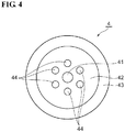
- FIG 4 is a sectional view illustrating an optical fiber 4 relating to a comparative example.
- the optical fiber 4 is a silica-based holey fiber and includes a core 41, an optical cladding 42 surrounding the core 41, a jacketing region 43 surrounding the optical cladding 42, and a protective coating layer which surrounds the jacketing layer 43 and is not shown in Fig. 3 .
- holes 44 are formed at vertexes of a regular hexagonal shape at a position in the main medium having the same composition as the core 41 such that the core 41 lies at the center of the hexagonal shape, whereby the effective refractive index of the optical cladding 42 is smaller than the refractive index of the core 41.
- the refractive index of the jacketing region 43 may be either the same as or different from the refractive index of the main medium of the optical cladding 42.
- the jacketing region 43 is a region to which the electric field of core-guided mode light hardly reaches and which does not have an influence on the optical properties of the optical fiber 4.
- the inside diameter of the jacketing region 43 (the outside diameter of the cladding 42) is equal to or more than three times the mode field diameter of core-guided mode light.
- the composition of the jacketing region 43 is substantially uniform from the internal circumferential part to the outer circumferential part.
- a compressive strained layer in which a compressive stress remains is formed at the outermost circumferential portion of the jacketing region 43.
- the outermost circumferential portion of the jacketing region 43 having a substantially uniform composition is formed as a compressive strained layer, so that the optical fiber 4 has excellent strength, without causing such problems as caused by providing a conventional carbon coating or glass having different viscosity around the outer circumference thereof.
- the optical fiber 4 can be manufactured at a low cost substantially in the same method as a method of manufacturing a usual holey optical fiber.
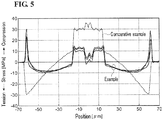
- Figure 5 is a graph showing three examples of stress profiles of an optical fiber 2, together with a stress profile of Comparative example which differs from the optical fiber 2 only in that no compressive strained layer is formed at the outermost circumferential portion of the jacketing region 13.
- a tensile stress remains at the vicinity of the outermost circumferential portion of the jacketing region.
- a compressive strained layer in which the compressive stress remains is formed at the outermost circumferential portion of the jacketing region.
- the optical fiber 2 has excellent strength because of such compressive strained layer.
- the residual compressive stress in the compressive strained layer of the jacketing region is preferably 10 MPa or more, and thereby the glass strength can advantageously be enhanced.
- the residual compressive stress in the compressive strained layer of the jacketing region is 30 MPa or more, and more preferably 100 MPa or more.
- the thickness of the compressive strained layer of the jacketing region is preferably 30% or less relative to the outside diameter of the jacketing region, whereby the tensile strain afforded inside can be kept small, enhancing the glass strength. Also, it becomes easy to afford a compressive stress of 10 MPa or more to the outermost circumferential portion of the jacketing region.
- the static fatigue coefficient of the optical fiber relating to the present invention be 20 or more. This will enable achieving desirable long-term reliability of the optical fiber.
- the static fatigue coefficient of the optical fiber is 25 or more, and more preferably 30 or more.
- the breaking strength of the optical fiber relating to the present invention be 400 kgf/mm 2 or more when a tensile rate of 5mm/min is applied.
- the circumferential deviation of the compressive stress of an optical fiber relating to the present invention is preferably 10 Mpa or less. This will allow a fiber curl to have a radius of curvature of 4 m or more.
- the measurement of a residual stress in an optical fiber can be done, for example, using the birefringence of the optical fiber as described in Japanese Patent Application Publication No. 2009-168813 .
- the measurement of the residual stress in the optical fiber can also be made from the variation quantity of refractive index and photoelastic coefficient inherent in the material by making a cross-sectional analysis of refractive indexes at a section of the optical fiber.
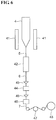
- FIG. 6 is a conceptional schematic diagram illustrating an embodiment of optical fiber manufacturing method of the invention.
- first prepared is an optical fiber preform 4 having a refractive index profile that is equivalent to the cross-sectional structure of an optical fiber to be produced. That is, the optical fiber preform 4 is a silica-based preform and includes a core, a depressed region surrounding the core, an optical cladding surrounding the depressed region, and a jacketing region surrounding the optical cladding.
- the optical fiber preform 4 can be prepared by an arbitrary method such as the VAD method, the OVD method, or the MCVD method.
- the optical fiber preform 4 is vertically put into a drawing furnace 41, and one end (bottom end) thereof is fused by heating in the drawing furnace 41 so as to be drawn into a fiber.
- a glass filament 5 is formed by this fiber drawing step.
- the glass filament 5 has a desired outside diameter that is the same as the glass diameter of an optical fiber to be produced.
- the glass filament 5 formed at the fiber drawing step is inserted into a stress imparting unit 42 after the temperature of the whole body has become lower than the glass transition point.
- the glass filament 5 inserted into the stress imparting unit 42 is re-heated there until the temperature of the outermost circumferential portion of the jacketing region becomes higher than the glass transition point, and as a result of cooling this part, a compressive strained layer is formed at the outermost circumferential portion of the jacketing region.
- this stress imparting step an glass fiber 6 in which a residual compressive strained layer is formed at the outermost circumferential portion of the jacketing region is produced.
- the glass fiber 6 produced by the stress imparting step is coated with an ultraviolet curable resin at a die 43, and thereafter such coating is hardened at a curing unit 44, resulting in a primary coating.
- an ultraviolet curable resin is applied at a die 45 and thereafter is hardened at a curing unit 46, resulting in a secondary coating.
- a coated optical fiber 7 is produced such that the circumference of the glass fiber 6 is covered with the primary coating and the secondary coating.
- the coated fiber 7 produced by the coating step is rolled up onto a bobbin 48 via a capstan 47.
- an optical fiber of the present invention can be manufactured by an optical fiber manufacturing method of the invention.
- the optical fiber manufacturing method of the present invention is such that the stress imparting step (the compressive strained layer is formed by the stress imparting unit 42) is only added to the latter part of the fiber drawing step (the drawing is done by the drawing furnace 41) in a conventional optical fiber manufacturing method.
- an optical fiber can be manufactured by drawing an optical fiber preform 4 that is similar to a conventional preform. Therefore, the optical fiber manufacturing method relating to the present invention enables easily affording a compressive stress to the glass outer circumference without changing the glass composition constituting the jacket layer of an optical fiber, allowing easy and low-cost manufacture of the optical fiber having excellent strength.
- Figure 7 shows a first example of stress imparting unit 42 used at the stress imparting step in the optical fiber manufacturing method relating to the present invention: region (a) is a top view thereof; and region (b) is a side view thereof.
- a compressive strained layer is formed in the following manner: a glass filament 5 is heated to a temperature higher than the glass transition point by means of irradiation of laser beams output from lasers 51 to 53, and when this part is cooled, the compressive strained layer is formed at the outermost circumferential portion of the jacketing region.
- the number of lasers used in such case may be one, but it is preferable to use two or more lasers.
- the heating of the glass filament 5 is equalized and accordingly the quantity of afforded compressive stress is equalized around the outer circumference of the glass filament 5 since the laser beams output from the plurality of lasers are irradiated from different directions to the glass filament 5.
- Figure 8 shows a second example of stress imparting unit 42 used at the stress imparting step in the optical fiber manufacturing method relating to the present invention: region (a) is a top view thereof; and region (b) is a side view thereof.
- laser beams output from the laser 51 are introduced into a tubular reflecting plate 54 via window 54a and partly irradiated to the glass filament 5 directly while the rest of the beams are irradiated to the glass filament 5 through reflection at the inner wall surface of the tubular reflecting plate 54.
- the inner wall surface of the reflecting plate 54 has a reflectance of 70% or more at the wavelength of the laser beams, and is made of metal-plated quartz, alumina, metal, or the like.
- laser beams are irradiated from various directions to the glass filament 5, and consequently the heating is equalized around the outer circumference of the glass filament 5 and hence the quantity of the compressive stress afforded thereby is also equalized.
- a plurality of lasers may be used.
- FIG. 9 shows a top view of a third example of stress imparting unit 42 used at the stress imparting step in the optical fiber manufacturing method relating to the present invention.
- a laser beam output from the laser 51 is introduced into the tubular reflecting plate 54 via the window 54a and diffused by a diffuser 55. Subsequently, a part of the diffused beam is directly irradiated to the glass filament 5 while the rest is irradiated to the glass filament 5 through reflection at the inner wall surface of the tubular reflecting plate 54.
- laser beams are irradiated from various directions to the glass filament 5, and consequently the heating is equalized around the outer circumference of the glass filament 5 and hence the quantity of the compressive stress afforded thereby is also equalized.
- a plurality of lasers may be used.
- lasers 51 to 53 in the first to third examples lasers capable of outputting a high-power infrared laser beam, such as a CO 2 laser or a copper-vapor laser, are suitably used, and also a laser which can output a CW laser beam is suitable. It is desirable to control laser beam strength by monitoring the temperature of the outer circumference of the glass filament 5 so as to obtain a desired temperature, so that an optical fiber having stable quality can be manufactured.
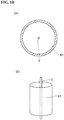
- Figure 10 shows a fourth example of stress imparting unit 42 used at the stress imparting step in the optical fiber manufacturing method relating to the present invention: region (a) is a top view thereof; and region (b) is a perspective view thereof.
- the glass filament 5 is heated to a temperature higher than the glass transition point by a heating furnace 61, and when this part is cooled, a compressive strained layer is formed at the outermost circumferential portion of the jacketing region.
- the heating furnace 61 is an annular furnace arranged to surround the glass filament 5 as its central axis, for example, such as Kanthal furnace, a resistance furnace, an induction furnace, or the like. It is preferable that the inside of the heating furnace 61 be filled with an inert gas such as N 2 gas, Ar gas, and He gas in a clean atmosphere.
- the heating furnace 61 preferably has a length of 100 mm or more so that the outermost circumferential portion of the glass filament 5 can be heated to a temperature higher than the glass transition point. Also, it is preferable to provide a mechanism for cooling the glass filament 5 that has come out of the heating furnace 61 upon being heated by the heating furnace 61, so that a stronger compressive stress can remain at the outer circumferential portion of the glass fiber 6.
- FIG 11 shows a top view of a fifth example of stress imparting unit 42 used at the stress imparting step in the optical fiber manufacturing method relating to the present invention.
- the glass filament 5 is heated by a burner 71 to a temperature higher than the glass transition point, and when this part is cooled, a compressive strained layer is formed at the outermost circumferential portion of the jacketing region.
- the burner 71 is one that can heat the glass filament 5 to a temperature higher than the glass transition point (about 1100°C), such as a plasma burner, an oxyhydrogen burner, or a methane burner, for example.
- the flame is preferably an anhydrous one, because otherwise the long-term glass strength may not be assured if an OH group adheres to the surface of the glass filament 5.
- the burner 71 is preferably a plasma burner that generates comparatively small wind pressure.
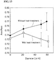
- Figure 12 is a graph illustrating a Raman scattering spectrum of silica glass and 800 cm -1 peak area A800 and 490 cm -1 peak area A490 of the spectrum.
- the peak area A800 is an area of the region between the spectrum of Raman scattering and the baseline drawn from wave number 880 to 740 cm -1 and corresponds to the quantity of SiO 2 glass network composed of six- membered ring.
- the peak area A490 is an area of the region between the spectrum of Raman scattering and the baseline drawn from wave number 525 to 475 cm -1 and corresponds to the quantity of a strained structure composed of four-membered ring.
- a known model of glass breakage is such that strained structures such as three-membered ring and four-membered ring that are generally inherent in the SiO 2 glass network composed of six-membered ring are selectively hydrolyzed, leading to breakage ( J. K. West et al., "Silica fracture Part II A ring opening model via hydrolysis", Journal of Materials Science 29 (1994) 5808-5816 ). Therefore, it is desired that the absolute quantity of three-membered ring and four-membered ring are lessened to increase the breaking strength of glass.
- Figure 13 is a graph showing the ratio (A490/A800) at each position in a section of an glass fiber 6, in the case where the heat treatment of a glass filament 5 is performed and in the case where the heat treatment of the glass filament 5 is not performed, respectively.
- the spectrum of Raman scattering at each position in the section of an optical fiber can be measured by scanning pump light having a beam diameter of 5 ⁇ m in a radial direction in the section.
- the ratio (A490/A800) at the outermost circumferential portion of the jacketing region was made smaller than the ratio (A490/A800) at the core by performing a heat treatment at a temperature below (Tg+500°C) and above the glass transition point Tg.
- the breaking strength of the optical fiber in a tensile test at a strain rate of 1%/min increased by 11% as compared with the case where no heat treatment was performed.
- optical fibers (Example 1 to 3) were prepared experimentally as the optical fiber 3, and optical characteristics (mode field diameter at a wavelength of 1.31 ⁇ m, 2 m cutoff wavelength, 22 m cable cutoff wavelength, zero dispersion wavelength, and bend loss at each bending diameter), residual compressive stresses in the optical fibers, and breaking strengths were obtained. As shown in Fig.
- the outside diameter of a first core 31 is expressed by 2r 1
- the outside diameter of a second core 32 is expressed by 2r 2
- the outside diameter of a depressed region 33 is expressed by 2r 3
- Ra is a ratio (r 1 /r 2 )
- Rb is a ratio (r 2 /r 3 ).
- the compressive stress was measured with a technique for detecting polarization rotation by photoelastic effect, and the average breaking strength was obtained by applying a tensile rate of 5 mm/min to a testing optical fiber of 500 mm in length.
- Table shows specifications of optical fibers in Examples 1 to 3.
- Table Example 1 Example 2
- Example 3 ⁇ 1 % 0.3 0.35 0.35
- Refractive index structure ⁇ 2 % 0.025 0.025 0.025 ⁇ 3 % -0.7 -0.6 to -0.5 -0.7 ⁇ 4 % 0.025 0.025 0.025 r1 ⁇ m 4 4 4 r2 ⁇ m 6.6667 9.30233 8.16327 r3 ⁇ m 12.4611 15.5039 12.184 Fiber diameter ⁇ m 125 125 125 Ra (r1/r2) 0.6 0.43 0.49 Rb (r2/r3) 0.535 0.6 0.67 Properties MFD @1.31 ⁇ m ⁇ m 8.6 8.6 8.6 2 m cutoff wavelength nm 1400 1400 1400 22 m cutoff wavelength nm ⁇ 1260 ⁇ 1260 ⁇ 1260 Zero dispersion wavelength nm ⁇ 1300 1300 to 1324 ⁇ 1300 Bend loss @R5 mm dB/turn ⁇ 0.1
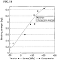
- Figure 14 is a graph showing the relationship between a residual stress and a breaking strength in an optical fiber.
- additional examples are shown in addition to Examples 1 to 3.
- an optical fiber having a trench-type profile or a similar profile In an optical fiber having a trench-type profile or a similar profile, less optical leakage occurs even if it is bent. Therefore, an optical fiber having such type of profile can advantageously be used for increasing the efficiency of housing and installation work of FTTx because it is highly reliable in terms of stress given during the installation work and storage.
- optical fiber relating to the present invention can suitably be used for submarine applications.
- Optical fibers installed on the sea bottom are difficult to repair, and therefore they are required of particularly long-time reliability.
- Optical fibers relating to the present invention are preferable because they are highly reliable with respect to stress.
- Optical fibers having a W-type refractive index profile of the embodiment and those having a trench-type profile of the comparative example are suitable for submarine applications.
- the temperature of an optical fiber at the time of entering into the die 43 for application of a resin is preferably 30°C or higher. In such case, the condensation reaction between the glass and a silane coupling material contained in the resin is accelerated, and hence the strength of glass can be expected to further increase.
- the deviation of temperature at the outer circumference of the optical fiber during heating for the stress imparting step is preferably less than 50°C.
- the circumferential deviation of the compressive stress can be made equal to or less than 10 MPa.
- the temperature of an optical fiber under drawing can be evaluated by observing the optical fiber under drawing from a plurality of angles with a pyrometer in which infrared light is used.
- L1/V is equal to or more than 0.003 second
- L2/V is equal to or less than 1 second
- L1 represents the length to the stress imparting unit L1 from the position at which the outside diameter of the optical fiber is decreased to 105% or less of desired outer diameter
- L2 represents the length of the stress imparting unit
- V represents the line speed of the optical fiber. It is possible to make the temperature of the optical fiber to be below the glass transition point by setting the cooling time of the optical fiber such that L1/V> 0.003 second holds.
- the viscosity decreasing part can be limited to the outer circumference of the optical fiber only, thereby enabling production of an optical fiber in which the compressive stress is afforded only to the outer circumference of the optical fiber. More preferably, L2/V is 0.5 second or less, and further more preferably, L2/V is 0.1 second or less.
- the tension given to the optical fiber glass at the stress imparting step is preferably 25 gms or more.
- the larger the tension given to the optical fiber the larger the compressive stress remaining at the outer circumference of the optical fiber.
- the tension is 50 gms or more.
- the present invention makes it possible to provide a residual compressive stress selectively only at the outside surface of the glass, notwithstanding an ordinary glass having a common glass composition is used as it is without adhering any particular material to the outside surface of glass, provided that the glass composition has been proved to be satisfactory in terms of optical properties.
- the glass composition has been proved to be satisfactory in terms of optical properties.
- tensile stress given to the optical fiber is canceled by the residual compressive stress, thereby restraining any flaw of the optical fiber surface from growing, it is possible to obtain an optical fiber in which its strength is enhanced.
- it is possible to significantly improve the reliability of the optical fiber easily without having an adverse influence on the manufacturing cost while conquering the problems of the conventional methods that have been contrived to strengthen an optical fiber.
- optical fibers of the present invention can be used for wiring of FTTx or optical fibers installed on the sea bottom.
Landscapes
- Physics & Mathematics (AREA)
- General Physics & Mathematics (AREA)
- Optics & Photonics (AREA)
- Engineering & Computer Science (AREA)
- Chemical & Material Sciences (AREA)
- Thermal Sciences (AREA)
- General Life Sciences & Earth Sciences (AREA)
- Geochemistry & Mineralogy (AREA)
- Manufacturing & Machinery (AREA)
- Life Sciences & Earth Sciences (AREA)
- Materials Engineering (AREA)
- Organic Chemistry (AREA)
- Glass Compositions (AREA)
- Manufacture, Treatment Of Glass Fibers (AREA)
- Optical Fibers, Optical Fiber Cores, And Optical Fiber Bundles (AREA)
Claims (15)
- Fibre optique à base de silice (2) comprenant un noyau (21), une région renfoncée (22) entourant le noyau (21), un placage optique (23) entourant la région renfoncée (22) et une région de chemisage (24) entourant le placage optique (23), la région renfoncée (22) ayant un indice de réfraction (n22) inférieur à l'indice de réfraction (n23) du placage optique (23), et le placage optique (23) ayant un indice de réfraction (n23) inférieur à l'indice de réfraction (n21) du noyau (21), la région de chemisage (24) ayant une composition totalement uniforme de la circonférence interne à la circonférence externe, la région de chemisage (24) ayant une couche compressive tendue ayant une contrainte de compression résiduelle sur la circonférence externe de la région de chemisage (24).
- Fibre optique selon la revendication 1, dans laquelle la contrainte de la couche compressive tendue est une contrainte de compression de 10 MPa ou plus.
- Fibre optique selon la revendication 1 ou 2, dans laquelle la couche compressive tendue a une épaisseur équivalente à 30 % ou moins du diamètre externe de la région de chemisage (13 ; 24 ; 35 ; 43).
- Fibre optique selon la revendication 1, 2 ou 3, dans laquelle le coefficient de fatigue statique est de 20 ou plus.
- Fibre optique selon l'une quelconque des revendications précédentes, dans laquelle la résistance à la rupture est de 400 kgf/mm2 ou plus lorsqu'un taux de traction de 5 mm/min est appliqué.
- Fibre optique selon l'une quelconque des revendications précédentes, dans laquelle le rapport (A490/A800) d'une zone de pic de 490 cm-1 A490 à une zone de pic de 800 cm-1 A800 du spectre de dispersion de Raman dans la partie circonférentielle externe de la région de chemisage (13 ; 24 ; 35 ; 43) est plus petit que le rapport (A490/A800) au noyau (11 ; 21 ; 31 ; 32 ; 41).
- Fibre optique selon l'une quelconque des revendications précédentes, dans laquelle la déviation circonférentielle de la contrainte de compression est de 10 MPa ou moins.
- Procédé de fabrication d'une fibre optique selon la revendication 1, le procédé comprenant une étape d'étirage de fibre, dans lequel un filament de verre ayant un diamètre externe souhaité est formé par chauffage et fusion d'une extrémité d'une préforme de fibre optique à base de silice comprenant un noyau (21), une région renfoncée (22) entourant le noyau (21), un placage optique (23) entourant la région renfoncée (22) et une région de chemisage (24) entourant le placage optique (23), la région de chemisage (24) ayant une composition uniforme ;
caractérisé par
une étape de communication de contrainte, dans laquelle la partie circonférentielle externe du filament de verre est réchauffée avec une unité de communication de contrainte à une température plus élevée qu'un point de transition vitreuse de la partie circonférentielle externe de la région de chemisage après que la température de la totalité du filament de verre formé dans l'étape d'étirage de fibre est devenue plus faible que le point de transition vitreuse et que, de la sorte, une couche compressive tendue est formée sur la partie circonférentielle externe de la région de chemisage. - Procédé de fabrication de fibre optique selon la revendication 8, dans lequel le filament de verre est chauffé par irradiation de faisceaux laser délivrés par un ou plusieurs lasers.
- Procédé de fabrication de fibre optique selon la revendication 8, dans lequel le filament de verre est chauffé par un four de chauffage annulaire entourant le filament de verre sur son axe central.
- Procédé de fabrication de fibre optique selon la revendication 8, dans lequel le filament de verre est chauffé en utilisant un brûleur.
- Procédé de fabrication de fibre optique selon l'une quelconque des revendications 8 à 11, dans lequel, à l'étape d'étirage, la fibre de filament de verre est étirée tout en étant tordue dans des directions alternées autour de son axe central.
- Procédé de fabrication de fibre optique selon l'une quelconque des revendications 8 à 12, dans lequel la déviation de température dans la circonférence externe du filament de verre au cours du chauffage à l'étape de communication de contrainte est inférieure à 50 °C.
- Procédé de fabrication de fibre optique selon l'une quelconque des revendications 8 à 13, dans lequel L1/V est de 0,003 seconde ou plus et L2/V est de 1 seconde ou moins, où V est une vitesse linéaire d'une fibre optique, L1 est une longueur s'étendant jusqu'à l'unité de communication de contrainte à partir de la position dans laquelle le diamètre externe du filament de verre est réduit à 105 % ou moins du diamètre externe souhaité et L2 est la longueur de l'unité de communication de contrainte.
- Procédé de fabrication de fibre optique selon l'une quelconque des revendications 8 à 14, dans lequel la tension appliquée à la fibre de verre optique à l'étape de communication de contrainte est de 25 gms ou plus.
Applications Claiming Priority (1)
| Application Number | Priority Date | Filing Date | Title |
|---|---|---|---|
| JP2009237313 | 2009-10-14 |
Publications (2)
| Publication Number | Publication Date |
|---|---|
| EP2312349A1 EP2312349A1 (fr) | 2011-04-20 |
| EP2312349B1 true EP2312349B1 (fr) | 2018-11-21 |
Family
ID=43383614
Family Applications (1)
| Application Number | Title | Priority Date | Filing Date |
|---|---|---|---|
| EP10187241.4A Active EP2312349B1 (fr) | 2009-10-14 | 2010-10-12 | Fibre optique et procédé de fabrication de fibre optique |
Country Status (5)
| Country | Link |
|---|---|
| US (2) | US8676014B2 (fr) |
| EP (1) | EP2312349B1 (fr) |
| JP (1) | JP2011102964A (fr) |
| CN (1) | CN102043194B (fr) |
| DK (1) | DK2312349T3 (fr) |
Families Citing this family (25)
| Publication number | Priority date | Publication date | Assignee | Title |
|---|---|---|---|---|
| US8488932B2 (en) * | 2010-02-26 | 2013-07-16 | Corning Incorporated | Optical fiber with increased mechanical strength |
| JP5372082B2 (ja) * | 2011-08-12 | 2013-12-18 | 株式会社フジクラ | 光ファイバ素線の製造方法および製造装置 |
| EP2748116B1 (fr) * | 2011-08-22 | 2015-11-25 | Corning Incorporated | Procédé de fabrication d'une fibre optique présentant des perturbations d'indice contrôlées |
| JP5533825B2 (ja) * | 2011-09-13 | 2014-06-25 | 住友電気工業株式会社 | 光ファイバ製造方法および光ファイバ |
| US8798420B2 (en) | 2012-03-14 | 2014-08-05 | Sumitomo Electric Industries, Ltd. | Multi-mode optical fiber |
| WO2014004832A2 (fr) * | 2012-06-27 | 2014-01-03 | Afl Telecommunications Llc | Système de rétroaction destiné à améliorer la stabilité d'un appareil de raccordement et d'effilage de fibres optiques basé sur un laser co2 |
| CN104834053A (zh) * | 2014-02-08 | 2015-08-12 | 住友电气工业株式会社 | 多模光纤及其制造方法 |
| JP5850992B1 (ja) * | 2014-07-30 | 2016-02-03 | 株式会社フジクラ | 光デバイス、及び、光デバイスの製造方法 |
| JP6658757B2 (ja) * | 2015-08-04 | 2020-03-04 | 住友電気工業株式会社 | 光接続部品 |
| JP6477890B2 (ja) | 2015-08-13 | 2019-03-06 | 住友電気工業株式会社 | 光接続部品 |
| CN107518862A (zh) * | 2016-06-20 | 2017-12-29 | 魏晋 | 集成光学相干与非相干成像系统的一种光纤及成像方法 |
| WO2019172197A1 (fr) * | 2018-03-06 | 2019-09-12 | 住友電気工業株式会社 | Fibre optique |
| DE112019002964T5 (de) * | 2018-06-14 | 2021-02-25 | Sintokogio, Ltd. | Dehnungselement, Verfahren zum Herstellen von Dehnungselementen und Sensor zum Messen physikalischer Größen |
| FR3093719B1 (fr) * | 2019-03-15 | 2022-08-05 | Univ Limoges | Procédé et dispositif de fabrication d’une fibre optique |
| CN110255881A (zh) * | 2019-06-27 | 2019-09-20 | 西安柯莱特信息科技有限公司 | 一种具有温度监控且可均匀加热光纤拉锥旋转的加热舱 |
| JPWO2021117825A1 (fr) * | 2019-12-13 | 2021-06-17 | ||
| US11971571B2 (en) * | 2020-02-21 | 2024-04-30 | Sumitomo Electric Industries, Ltd. | Optical fiber |
| JP7501019B2 (ja) * | 2020-03-19 | 2024-06-18 | 住友電気工業株式会社 | マルチコア光ファイバ |
| CN111505763B (zh) * | 2020-05-24 | 2022-10-21 | 武汉库克光电技术有限公司 | 一种弯曲不敏感单模光纤 |
| JP7763178B2 (ja) * | 2020-09-17 | 2025-10-31 | 古河電気工業株式会社 | マルチコアファイバ |
| WO2022072613A1 (fr) | 2020-09-30 | 2022-04-07 | Corning Incorporated | Procédés et systèmes de traitement de fibre optique |
| US20240174546A1 (en) * | 2021-07-27 | 2024-05-30 | Dstar Communications, Inc. | Microgravity crucible-controlled manufacturing |
| CN114966960B (zh) * | 2022-06-28 | 2023-03-21 | 中山大学 | 一种用于海缆的中心折射率抬高型环芯光纤 |
| WO2024195010A1 (fr) * | 2023-03-20 | 2024-09-26 | 日本電信電話株式会社 | Guide d'ondes a fibre monocristalline |
| WO2025094480A1 (fr) * | 2023-11-02 | 2025-05-08 | 株式会社フジクラ | Fibre optique |
Citations (2)
| Publication number | Priority date | Publication date | Assignee | Title |
|---|---|---|---|---|
| JP2006058494A (ja) * | 2004-08-18 | 2006-03-02 | Fujikura Ltd | 光ファイバ素線及びその製造方法 |
| JP2007197273A (ja) * | 2006-01-27 | 2007-08-09 | Fujikura Ltd | 光ファイバ素線及びその製造方法 |
Family Cites Families (18)
| Publication number | Priority date | Publication date | Assignee | Title |
|---|---|---|---|---|
| US4243298A (en) * | 1978-10-06 | 1981-01-06 | International Telephone And Telegraph Corporation | High-strength optical preforms and fibers with thin, high-compression outer layers |
| JPS6055304A (ja) * | 1983-09-06 | 1985-03-30 | Nippon Telegr & Teleph Corp <Ntt> | 高強度光フアイバ |
| JPS6082817A (ja) | 1983-10-13 | 1985-05-11 | Matsushita Electric Ind Co Ltd | 流量測定装置 |
| JPS6236070A (ja) | 1985-08-09 | 1987-02-17 | 品川白煉瓦株式会社 | 吹付け施工用キャスタブルの吹付け施工方法 |
| JPH0648325B2 (ja) | 1988-07-18 | 1994-06-22 | 住友電気工業株式会社 | 光ファイバ及びその製造方法 |
| US5057781A (en) | 1989-07-31 | 1991-10-15 | At&T Bell Laboratories | Measuring and controlling the thickness of a conductive coating on an optical fiber |
| JPH0465327A (ja) | 1990-07-02 | 1992-03-02 | Sumitomo Electric Ind Ltd | Tiドープ層付石英光ファイバの製造方法 |
| JPH04254431A (ja) * | 1991-02-05 | 1992-09-09 | Fujikura Ltd | 石英系光ファイバ母材およびその線引き方法 |
| JPH05124831A (ja) | 1991-07-30 | 1993-05-21 | Fujikura Ltd | 光フアイバの製造方法 |
| JP2001114527A (ja) * | 1999-10-14 | 2001-04-24 | Sumitomo Electric Ind Ltd | 光ファイバの製造方法 |
| US6625363B2 (en) * | 2001-06-06 | 2003-09-23 | Nufern | Cladding-pumped optical fiber |
| KR100417000B1 (ko) * | 2001-12-03 | 2004-02-05 | 삼성전자주식회사 | 저 편광 모드 분산을 위한 장치 |
| JP2003207675A (ja) * | 2002-01-11 | 2003-07-25 | Sumitomo Electric Ind Ltd | 石英系光ファイバ及びその製造方法 |
| DE10225773B4 (de) * | 2002-06-10 | 2005-03-31 | Heraeus Tenevo Ag | Jacketrohr aus synthetisch hergestelltem Quarzglas |
| JP4558368B2 (ja) | 2004-04-09 | 2010-10-06 | 古河電気工業株式会社 | 光ファイバの製造方法 |
| JP2005320191A (ja) * | 2004-05-07 | 2005-11-17 | Fujikura Ltd | 光ファイバ素線の製造方法、光ファイバ素線の製造装置 |
| JP5124831B2 (ja) | 2007-08-30 | 2013-01-23 | 株式会社リコー | 画像計測装置および画像形成装置 |
| KR100958185B1 (ko) * | 2008-01-14 | 2010-05-14 | 광주과학기술원 | 광섬유의 잔류응력 측정장치 |
-
2010
- 2010-08-31 JP JP2010194289A patent/JP2011102964A/ja active Pending
- 2010-10-12 EP EP10187241.4A patent/EP2312349B1/fr active Active
- 2010-10-12 DK DK10187241.4T patent/DK2312349T3/en active
- 2010-10-13 US US12/903,798 patent/US8676014B2/en active Active
- 2010-10-14 CN CN201010509755.6A patent/CN102043194B/zh active Active
-
2014
- 2014-01-24 US US14/163,433 patent/US8909016B2/en active Active
Patent Citations (2)
| Publication number | Priority date | Publication date | Assignee | Title |
|---|---|---|---|---|
| JP2006058494A (ja) * | 2004-08-18 | 2006-03-02 | Fujikura Ltd | 光ファイバ素線及びその製造方法 |
| JP2007197273A (ja) * | 2006-01-27 | 2007-08-09 | Fujikura Ltd | 光ファイバ素線及びその製造方法 |
Also Published As
| Publication number | Publication date |
|---|---|
| JP2011102964A (ja) | 2011-05-26 |
| DK2312349T3 (en) | 2019-01-14 |
| EP2312349A1 (fr) | 2011-04-20 |
| CN102043194A (zh) | 2011-05-04 |
| US20140137604A1 (en) | 2014-05-22 |
| CN102043194B (zh) | 2015-11-25 |
| US20110085768A1 (en) | 2011-04-14 |
| US8676014B2 (en) | 2014-03-18 |
| US8909016B2 (en) | 2014-12-09 |
Similar Documents
| Publication | Publication Date | Title |
|---|---|---|
| US8909016B2 (en) | Optical fiber and method of manufacturing optical fiber | |
| EP2790045B1 (fr) | FIBRE OPTIQUE ET SYSTèME DE TRANSMISSION OPTIQUE | |
| US9120693B2 (en) | Multi-core optical fiber ribbons and methods for making the same | |
| US8385703B2 (en) | High numerical aperture multimode optical fiber | |
| EP3032301B1 (fr) | Fibre optique | |
| CN110073257A (zh) | 具有氯掺杂纤芯的低损耗单模光纤 | |
| CN101932961A (zh) | 耐弯曲多模光纤 | |
| US10228509B2 (en) | Low attenuation fiber with viscosity matched core and inner clad | |
| CA2746061A1 (fr) | Fibre optique et procede de fabrication connexe | |
| US11971571B2 (en) | Optical fiber | |
| CN100343704C (zh) | 接合损耗低的光纤及其制造方法 | |
| US20230417983A1 (en) | Co-alkali doped optical fibers | |
| CN115951445B (zh) | 抗弯曲高耐压光纤及其制备方法 | |
| CN1395121A (zh) | 负色散单模光纤 | |
| EP4321910A1 (fr) | Fibre optique | |
| HK1086338B (en) | Optical fibre having low splice loss and method for making it |
Legal Events
| Date | Code | Title | Description |
|---|---|---|---|
| PUAI | Public reference made under article 153(3) epc to a published international application that has entered the european phase |
Free format text: ORIGINAL CODE: 0009012 |
|
| AK | Designated contracting states |
Kind code of ref document: A1 Designated state(s): AL AT BE BG CH CY CZ DE DK EE ES FI FR GB GR HR HU IE IS IT LI LT LU LV MC MK MT NL NO PL PT RO RS SE SI SK SM TR |
|
| AX | Request for extension of the european patent |
Extension state: BA ME |
|
| 17P | Request for examination filed |
Effective date: 20110722 |
|
| 17Q | First examination report despatched |
Effective date: 20151106 |
|
| STAA | Information on the status of an ep patent application or granted ep patent |
Free format text: STATUS: EXAMINATION IS IN PROGRESS |
|
| GRAJ | Information related to disapproval of communication of intention to grant by the applicant or resumption of examination proceedings by the epo deleted |
Free format text: ORIGINAL CODE: EPIDOSDIGR1 |
|
| STAA | Information on the status of an ep patent application or granted ep patent |
Free format text: STATUS: GRANT OF PATENT IS INTENDED |
|
| GRAP | Despatch of communication of intention to grant a patent |
Free format text: ORIGINAL CODE: EPIDOSNIGR1 |
|
| RIC1 | Information provided on ipc code assigned before grant |
Ipc: C03B 37/027 20060101ALI20180625BHEP Ipc: G02B 6/036 20060101AFI20180625BHEP Ipc: G02B 6/02 20060101ALI20180625BHEP |
|
| INTG | Intention to grant announced |
Effective date: 20180713 |
|
| RIN1 | Information on inventor provided before grant (corrected) |
Inventor name: IKECHI, MAKI Inventor name: HANURA, TETSUYA Inventor name: HIRANO, MASAAKI Inventor name: NAKANISHI, TETSUYA |
|
| GRAS | Grant fee paid |
Free format text: ORIGINAL CODE: EPIDOSNIGR3 |
|
| GRAA | (expected) grant |
Free format text: ORIGINAL CODE: 0009210 |
|
| STAA | Information on the status of an ep patent application or granted ep patent |
Free format text: STATUS: THE PATENT HAS BEEN GRANTED |
|
| AK | Designated contracting states |
Kind code of ref document: B1 Designated state(s): AL AT BE BG CH CY CZ DE DK EE ES FI FR GB GR HR HU IE IS IT LI LT LU LV MC MK MT NL NO PL PT RO RS SE SI SK SM TR |
|
| REG | Reference to a national code |
Ref country code: CH Ref legal event code: EP |
|
| REG | Reference to a national code |
Ref country code: IE Ref legal event code: FG4D |
|
| REG | Reference to a national code |
Ref country code: DE Ref legal event code: R096 Ref document number: 602010055231 Country of ref document: DE |
|
| REG | Reference to a national code |
Ref country code: AT Ref legal event code: REF Ref document number: 1068221 Country of ref document: AT Kind code of ref document: T Effective date: 20181215 |
|
| REG | Reference to a national code |
Ref country code: NL Ref legal event code: FP |
|
| REG | Reference to a national code |
Ref country code: DK Ref legal event code: T3 Effective date: 20190106 |
|
| REG | Reference to a national code |
Ref country code: AT Ref legal event code: MK05 Ref document number: 1068221 Country of ref document: AT Kind code of ref document: T Effective date: 20181121 |
|
| PG25 | Lapsed in a contracting state [announced via postgrant information from national office to epo] |
Ref country code: AT Free format text: LAPSE BECAUSE OF FAILURE TO SUBMIT A TRANSLATION OF THE DESCRIPTION OR TO PAY THE FEE WITHIN THE PRESCRIBED TIME-LIMIT Effective date: 20181121 Ref country code: HR Free format text: LAPSE BECAUSE OF FAILURE TO SUBMIT A TRANSLATION OF THE DESCRIPTION OR TO PAY THE FEE WITHIN THE PRESCRIBED TIME-LIMIT Effective date: 20181121 Ref country code: LV Free format text: LAPSE BECAUSE OF FAILURE TO SUBMIT A TRANSLATION OF THE DESCRIPTION OR TO PAY THE FEE WITHIN THE PRESCRIBED TIME-LIMIT Effective date: 20181121 Ref country code: NO Free format text: LAPSE BECAUSE OF FAILURE TO SUBMIT A TRANSLATION OF THE DESCRIPTION OR TO PAY THE FEE WITHIN THE PRESCRIBED TIME-LIMIT Effective date: 20190221 Ref country code: FI Free format text: LAPSE BECAUSE OF FAILURE TO SUBMIT A TRANSLATION OF THE DESCRIPTION OR TO PAY THE FEE WITHIN THE PRESCRIBED TIME-LIMIT Effective date: 20181121 Ref country code: IS Free format text: LAPSE BECAUSE OF FAILURE TO SUBMIT A TRANSLATION OF THE DESCRIPTION OR TO PAY THE FEE WITHIN THE PRESCRIBED TIME-LIMIT Effective date: 20190321 Ref country code: BG Free format text: LAPSE BECAUSE OF FAILURE TO SUBMIT A TRANSLATION OF THE DESCRIPTION OR TO PAY THE FEE WITHIN THE PRESCRIBED TIME-LIMIT Effective date: 20190221 Ref country code: ES Free format text: LAPSE BECAUSE OF FAILURE TO SUBMIT A TRANSLATION OF THE DESCRIPTION OR TO PAY THE FEE WITHIN THE PRESCRIBED TIME-LIMIT Effective date: 20181121 Ref country code: LT Free format text: LAPSE BECAUSE OF FAILURE TO SUBMIT A TRANSLATION OF THE DESCRIPTION OR TO PAY THE FEE WITHIN THE PRESCRIBED TIME-LIMIT Effective date: 20181121 |
|
| PG25 | Lapsed in a contracting state [announced via postgrant information from national office to epo] |
Ref country code: GR Free format text: LAPSE BECAUSE OF FAILURE TO SUBMIT A TRANSLATION OF THE DESCRIPTION OR TO PAY THE FEE WITHIN THE PRESCRIBED TIME-LIMIT Effective date: 20190222 Ref country code: AL Free format text: LAPSE BECAUSE OF FAILURE TO SUBMIT A TRANSLATION OF THE DESCRIPTION OR TO PAY THE FEE WITHIN THE PRESCRIBED TIME-LIMIT Effective date: 20181121 Ref country code: PT Free format text: LAPSE BECAUSE OF FAILURE TO SUBMIT A TRANSLATION OF THE DESCRIPTION OR TO PAY THE FEE WITHIN THE PRESCRIBED TIME-LIMIT Effective date: 20190321 Ref country code: SE Free format text: LAPSE BECAUSE OF FAILURE TO SUBMIT A TRANSLATION OF THE DESCRIPTION OR TO PAY THE FEE WITHIN THE PRESCRIBED TIME-LIMIT Effective date: 20181121 Ref country code: RS Free format text: LAPSE BECAUSE OF FAILURE TO SUBMIT A TRANSLATION OF THE DESCRIPTION OR TO PAY THE FEE WITHIN THE PRESCRIBED TIME-LIMIT Effective date: 20181121 |
|
| PG25 | Lapsed in a contracting state [announced via postgrant information from national office to epo] |
Ref country code: PL Free format text: LAPSE BECAUSE OF FAILURE TO SUBMIT A TRANSLATION OF THE DESCRIPTION OR TO PAY THE FEE WITHIN THE PRESCRIBED TIME-LIMIT Effective date: 20181121 Ref country code: CZ Free format text: LAPSE BECAUSE OF FAILURE TO SUBMIT A TRANSLATION OF THE DESCRIPTION OR TO PAY THE FEE WITHIN THE PRESCRIBED TIME-LIMIT Effective date: 20181121 Ref country code: IT Free format text: LAPSE BECAUSE OF FAILURE TO SUBMIT A TRANSLATION OF THE DESCRIPTION OR TO PAY THE FEE WITHIN THE PRESCRIBED TIME-LIMIT Effective date: 20181121 |
|
| REG | Reference to a national code |
Ref country code: DE Ref legal event code: R097 Ref document number: 602010055231 Country of ref document: DE |
|
| PG25 | Lapsed in a contracting state [announced via postgrant information from national office to epo] |
Ref country code: RO Free format text: LAPSE BECAUSE OF FAILURE TO SUBMIT A TRANSLATION OF THE DESCRIPTION OR TO PAY THE FEE WITHIN THE PRESCRIBED TIME-LIMIT Effective date: 20181121 Ref country code: SK Free format text: LAPSE BECAUSE OF FAILURE TO SUBMIT A TRANSLATION OF THE DESCRIPTION OR TO PAY THE FEE WITHIN THE PRESCRIBED TIME-LIMIT Effective date: 20181121 Ref country code: SM Free format text: LAPSE BECAUSE OF FAILURE TO SUBMIT A TRANSLATION OF THE DESCRIPTION OR TO PAY THE FEE WITHIN THE PRESCRIBED TIME-LIMIT Effective date: 20181121 Ref country code: EE Free format text: LAPSE BECAUSE OF FAILURE TO SUBMIT A TRANSLATION OF THE DESCRIPTION OR TO PAY THE FEE WITHIN THE PRESCRIBED TIME-LIMIT Effective date: 20181121 |
|
| PLBE | No opposition filed within time limit |
Free format text: ORIGINAL CODE: 0009261 |
|
| STAA | Information on the status of an ep patent application or granted ep patent |
Free format text: STATUS: NO OPPOSITION FILED WITHIN TIME LIMIT |
|
| 26N | No opposition filed |
Effective date: 20190822 |
|
| PG25 | Lapsed in a contracting state [announced via postgrant information from national office to epo] |
Ref country code: SI Free format text: LAPSE BECAUSE OF FAILURE TO SUBMIT A TRANSLATION OF THE DESCRIPTION OR TO PAY THE FEE WITHIN THE PRESCRIBED TIME-LIMIT Effective date: 20181121 |
|
| PG25 | Lapsed in a contracting state [announced via postgrant information from national office to epo] |
Ref country code: TR Free format text: LAPSE BECAUSE OF FAILURE TO SUBMIT A TRANSLATION OF THE DESCRIPTION OR TO PAY THE FEE WITHIN THE PRESCRIBED TIME-LIMIT Effective date: 20181121 |
|
| REG | Reference to a national code |
Ref country code: DE Ref legal event code: R119 Ref document number: 602010055231 Country of ref document: DE |
|
| PG25 | Lapsed in a contracting state [announced via postgrant information from national office to epo] |
Ref country code: MC Free format text: LAPSE BECAUSE OF FAILURE TO SUBMIT A TRANSLATION OF THE DESCRIPTION OR TO PAY THE FEE WITHIN THE PRESCRIBED TIME-LIMIT Effective date: 20181121 |
|
| REG | Reference to a national code |
Ref country code: CH Ref legal event code: PL |
|
| PG25 | Lapsed in a contracting state [announced via postgrant information from national office to epo] |
Ref country code: CH Free format text: LAPSE BECAUSE OF NON-PAYMENT OF DUE FEES Effective date: 20191031 Ref country code: LI Free format text: LAPSE BECAUSE OF NON-PAYMENT OF DUE FEES Effective date: 20191031 Ref country code: LU Free format text: LAPSE BECAUSE OF NON-PAYMENT OF DUE FEES Effective date: 20191012 Ref country code: DE Free format text: LAPSE BECAUSE OF NON-PAYMENT OF DUE FEES Effective date: 20200501 |
|
| REG | Reference to a national code |
Ref country code: BE Ref legal event code: MM Effective date: 20191031 |
|
| PG25 | Lapsed in a contracting state [announced via postgrant information from national office to epo] |
Ref country code: BE Free format text: LAPSE BECAUSE OF NON-PAYMENT OF DUE FEES Effective date: 20191031 |
|
| GBPC | Gb: european patent ceased through non-payment of renewal fee |
Effective date: 20191012 |
|
| PG25 | Lapsed in a contracting state [announced via postgrant information from national office to epo] |
Ref country code: IE Free format text: LAPSE BECAUSE OF NON-PAYMENT OF DUE FEES Effective date: 20191012 Ref country code: GB Free format text: LAPSE BECAUSE OF NON-PAYMENT OF DUE FEES Effective date: 20191012 |
|
| PG25 | Lapsed in a contracting state [announced via postgrant information from national office to epo] |
Ref country code: CY Free format text: LAPSE BECAUSE OF FAILURE TO SUBMIT A TRANSLATION OF THE DESCRIPTION OR TO PAY THE FEE WITHIN THE PRESCRIBED TIME-LIMIT Effective date: 20181121 |
|
| PG25 | Lapsed in a contracting state [announced via postgrant information from national office to epo] |
Ref country code: HU Free format text: LAPSE BECAUSE OF FAILURE TO SUBMIT A TRANSLATION OF THE DESCRIPTION OR TO PAY THE FEE WITHIN THE PRESCRIBED TIME-LIMIT; INVALID AB INITIO Effective date: 20101012 Ref country code: MT Free format text: LAPSE BECAUSE OF FAILURE TO SUBMIT A TRANSLATION OF THE DESCRIPTION OR TO PAY THE FEE WITHIN THE PRESCRIBED TIME-LIMIT Effective date: 20181121 |
|
| PG25 | Lapsed in a contracting state [announced via postgrant information from national office to epo] |
Ref country code: MK Free format text: LAPSE BECAUSE OF FAILURE TO SUBMIT A TRANSLATION OF THE DESCRIPTION OR TO PAY THE FEE WITHIN THE PRESCRIBED TIME-LIMIT Effective date: 20181121 |
|
| P01 | Opt-out of the competence of the unified patent court (upc) registered |
Effective date: 20230515 |
|
| PGFP | Annual fee paid to national office [announced via postgrant information from national office to epo] |
Ref country code: NL Payment date: 20250912 Year of fee payment: 16 |
|
| PGFP | Annual fee paid to national office [announced via postgrant information from national office to epo] |
Ref country code: FR Payment date: 20250908 Year of fee payment: 16 |
|
| PGFP | Annual fee paid to national office [announced via postgrant information from national office to epo] |
Ref country code: DK Payment date: 20251014 Year of fee payment: 16 |