EP2310163B1 - Method for eccentrically orienting a laser cutting beam in relation to a nozzle axis and for cutting at an angle; corresponding laser machining head and laser machining tool - Google Patents
Method for eccentrically orienting a laser cutting beam in relation to a nozzle axis and for cutting at an angle; corresponding laser machining head and laser machining tool Download PDFInfo
- Publication number
- EP2310163B1 EP2310163B1 EP09768834.5A EP09768834A EP2310163B1 EP 2310163 B1 EP2310163 B1 EP 2310163B1 EP 09768834 A EP09768834 A EP 09768834A EP 2310163 B1 EP2310163 B1 EP 2310163B1
- Authority
- EP
- European Patent Office
- Prior art keywords
- cutting
- laser
- workpiece
- nozzle
- oblique
- Prior art date
- Legal status (The legal status is an assumption and is not a legal conclusion. Google has not performed a legal analysis and makes no representation as to the accuracy of the status listed.)
- Active
Links
Images

Classifications
-
- B—PERFORMING OPERATIONS; TRANSPORTING
- B23—MACHINE TOOLS; METAL-WORKING NOT OTHERWISE PROVIDED FOR
- B23K—SOLDERING OR UNSOLDERING; WELDING; CLADDING OR PLATING BY SOLDERING OR WELDING; CUTTING BY APPLYING HEAT LOCALLY, e.g. FLAME CUTTING; WORKING BY LASER BEAM
- B23K26/00—Working by laser beam, e.g. welding, cutting or boring
- B23K26/14—Working by laser beam, e.g. welding, cutting or boring using a fluid stream, e.g. a jet of gas, in conjunction with the laser beam; Nozzles therefor
-
- B—PERFORMING OPERATIONS; TRANSPORTING
- B23—MACHINE TOOLS; METAL-WORKING NOT OTHERWISE PROVIDED FOR
- B23K—SOLDERING OR UNSOLDERING; WELDING; CLADDING OR PLATING BY SOLDERING OR WELDING; CUTTING BY APPLYING HEAT LOCALLY, e.g. FLAME CUTTING; WORKING BY LASER BEAM
- B23K26/00—Working by laser beam, e.g. welding, cutting or boring
- B23K26/02—Positioning or observing the workpiece, e.g. with respect to the point of impact; Aligning, aiming or focusing the laser beam
- B23K26/04—Automatically aligning, aiming or focusing the laser beam, e.g. using the back-scattered light
- B23K26/042—Automatically aligning the laser beam
- B23K26/043—Automatically aligning the laser beam along the beam path, i.e. alignment of laser beam axis relative to laser beam apparatus
-
- B—PERFORMING OPERATIONS; TRANSPORTING
- B23—MACHINE TOOLS; METAL-WORKING NOT OTHERWISE PROVIDED FOR
- B23K—SOLDERING OR UNSOLDERING; WELDING; CLADDING OR PLATING BY SOLDERING OR WELDING; CUTTING BY APPLYING HEAT LOCALLY, e.g. FLAME CUTTING; WORKING BY LASER BEAM
- B23K26/00—Working by laser beam, e.g. welding, cutting or boring
- B23K26/02—Positioning or observing the workpiece, e.g. with respect to the point of impact; Aligning, aiming or focusing the laser beam
- B23K26/04—Automatically aligning, aiming or focusing the laser beam, e.g. using the back-scattered light
- B23K26/046—Automatically focusing the laser beam
- B23K26/048—Automatically focusing the laser beam by controlling the distance between laser head and workpiece
-
- B—PERFORMING OPERATIONS; TRANSPORTING
- B23—MACHINE TOOLS; METAL-WORKING NOT OTHERWISE PROVIDED FOR
- B23K—SOLDERING OR UNSOLDERING; WELDING; CLADDING OR PLATING BY SOLDERING OR WELDING; CUTTING BY APPLYING HEAT LOCALLY, e.g. FLAME CUTTING; WORKING BY LASER BEAM
- B23K26/00—Working by laser beam, e.g. welding, cutting or boring
- B23K26/02—Positioning or observing the workpiece, e.g. with respect to the point of impact; Aligning, aiming or focusing the laser beam
- B23K26/06—Shaping the laser beam, e.g. by masks or multi-focusing
- B23K26/064—Shaping the laser beam, e.g. by masks or multi-focusing by means of optical elements, e.g. lenses, mirrors or prisms
-
- B—PERFORMING OPERATIONS; TRANSPORTING
- B23—MACHINE TOOLS; METAL-WORKING NOT OTHERWISE PROVIDED FOR
- B23K—SOLDERING OR UNSOLDERING; WELDING; CLADDING OR PLATING BY SOLDERING OR WELDING; CUTTING BY APPLYING HEAT LOCALLY, e.g. FLAME CUTTING; WORKING BY LASER BEAM
- B23K26/00—Working by laser beam, e.g. welding, cutting or boring
- B23K26/12—Working by laser beam, e.g. welding, cutting or boring in a special atmosphere, e.g. in an enclosure
-
- B—PERFORMING OPERATIONS; TRANSPORTING
- B23—MACHINE TOOLS; METAL-WORKING NOT OTHERWISE PROVIDED FOR
- B23K—SOLDERING OR UNSOLDERING; WELDING; CLADDING OR PLATING BY SOLDERING OR WELDING; CUTTING BY APPLYING HEAT LOCALLY, e.g. FLAME CUTTING; WORKING BY LASER BEAM
- B23K26/00—Working by laser beam, e.g. welding, cutting or boring
- B23K26/14—Working by laser beam, e.g. welding, cutting or boring using a fluid stream, e.g. a jet of gas, in conjunction with the laser beam; Nozzles therefor
- B23K26/1435—Working by laser beam, e.g. welding, cutting or boring using a fluid stream, e.g. a jet of gas, in conjunction with the laser beam; Nozzles therefor involving specially adapted flow control means
- B23K26/1436—Working by laser beam, e.g. welding, cutting or boring using a fluid stream, e.g. a jet of gas, in conjunction with the laser beam; Nozzles therefor involving specially adapted flow control means for pressure control
-
- B—PERFORMING OPERATIONS; TRANSPORTING
- B23—MACHINE TOOLS; METAL-WORKING NOT OTHERWISE PROVIDED FOR
- B23K—SOLDERING OR UNSOLDERING; WELDING; CLADDING OR PLATING BY SOLDERING OR WELDING; CUTTING BY APPLYING HEAT LOCALLY, e.g. FLAME CUTTING; WORKING BY LASER BEAM
- B23K26/00—Working by laser beam, e.g. welding, cutting or boring
- B23K26/14—Working by laser beam, e.g. welding, cutting or boring using a fluid stream, e.g. a jet of gas, in conjunction with the laser beam; Nozzles therefor
- B23K26/1462—Nozzles; Features related to nozzles
- B23K26/1464—Supply to, or discharge from, nozzles of media, e.g. gas, powder, wire
- B23K26/1476—Features inside the nozzle for feeding the fluid stream through the nozzle
-
- B—PERFORMING OPERATIONS; TRANSPORTING
- B23—MACHINE TOOLS; METAL-WORKING NOT OTHERWISE PROVIDED FOR
- B23K—SOLDERING OR UNSOLDERING; WELDING; CLADDING OR PLATING BY SOLDERING OR WELDING; CUTTING BY APPLYING HEAT LOCALLY, e.g. FLAME CUTTING; WORKING BY LASER BEAM
- B23K26/00—Working by laser beam, e.g. welding, cutting or boring
- B23K26/36—Removing material
- B23K26/38—Removing material by boring or cutting
Definitions
- the present invention relates to a method for laser beam oblique cutting of a workpiece in which a supersonic cutting gas flow emerging from a cutting gas nozzle is aligned at a slant angle to the workpiece surface, and wherein the workpiece and the laser cutting beam are moved relative to each other in the laser beam oblique cutting, the slant angle perpendicular to a Feed direction runs.
- the invention also relates to a laser processing machine for laser beam oblique cutting of a workpiece, comprising: a cutting gas nozzle which can be oriented at an oblique cutting angle relative to a workpiece surface to produce a supersonic cutting gas stream, a movement device for moving the workpiece and the laser cutting beam relative to each other at an oblique cutting angle at right angles to a feed direction, and a laser processing head for positioning a laser cutting beam at a position on the workpiece surface.
- a planar cut surface can also be produced in the case of an oblique cut on a pipe, so that the welding of the cut edges is considerably simplified. It is understood that the oblique cutting can be made not only on tubular, but also in particular on thick, plate-shaped workpieces in order to weld them easier to each other at the oblique cutting edges formed during oblique cutting.
- the above-described laser beam oblique cutting process is far from being mastered, i. It must be expected with significant feed reduction (with a slanted cutting angle of 45 ° to 70%) and significant quality losses compared to conventional laser beam cutting with aligned perpendicular to the workpiece surface laser cutting beam.
- the cut edges produced in laser beam oblique cutting showed different surface qualities as a function of the oblique cutting angle, wherein a sharp edge formation is observed at one cut edge and a rough surface structure at the other cut edge.
- D2 JP05057470 which is based on the preamble of claim 1, discloses a known method for laser beam oblique cutting of a workpiece.
- This object is achieved by a method of the type mentioned, in which during the relative movement, the position of the laser cutting beam is set on the workpiece surface so that the laser cutting beam impinges on the workpiece surface in a high pressure area formed within the supersonic cutting gas flow.
- the position of the high-pressure region within the supersonic cutting gas flow in this case depends on the possibly during laser cutting changing oblique cutting angle.
- the high-pressure region and thus the position of the laser cutting beam on the workpiece surface are offset for angles at which the laser cutting beam is not aligned perpendicular to the workpiece surface to the nozzle axis of the cutting gas nozzle, which corresponds to the center of supersonic cutting gas flow.
- the inventors have recognized that a misalignment between the laser cutting beam and the center of supersonic cutting gas flow is not only favorable in the production of bores (trephining) but also in the laser beam oblique cutting, i.
- the cutting gas dynamics is the limiting factor: A large part of the cutting gas flows away from the workpiece surface running obliquely to the supersonic cutting gas stream and thus is no longer available for the cutting process, which is why the static pressure level generated in this case in the kerf is too low.
- a displacement of the cutting gap can be achieved in a fluidically favorable area.
- the displacement of the laser cutting beam or the cutting gap takes place at right angles to the feed direction and by a defined value, which depends on the (variable) oblique cutting angle.
- the thus improved coupling of supersonic cutting gas flow in the kerf results in an increase of the static pressure level in the kerf by several orders of magnitude result. Exemplary numerical flow calculations resulted in an increase of approximately 350% compared to the previous process variant.
- the variation of the oblique cutting angle is in this case particularly necessary when obliquely cutting pipes, since the oblique cutting angle perpendicular to the feed direction, for example between - 45 ° and 45 ° must be varied to produce a flat cutting surface at a 45 ° section on a pipe.
- Orientation of the workpiece is the high pressure area on the workpiece here in the center of the supersonic cutting gas flow, in non-rectangular orientation, the position of the high pressure area thereof and varies with the slanted cutting angle, so that the position of the laser beam are tracked on the workpiece to ensure that the laser beam remains in the high-pressure area during the oblique cutting.
- the distance between the cutting gas nozzle and the workpiece is determined.
- the distance between the cutting gas nozzle and the workpiece usually changes during the oblique cutting process with the change of the oblique cutting angle. Since the position of the high-pressure region on the workpiece also depends on the distance between the cutting gas nozzle and the workpiece, it is favorable to detect the distance as continuously as possible during the oblique cutting process and to use the detected distance for adjusting or adjusting the position of the laser cutting beam.
- the capacitance between the cutting gas nozzle and the workpiece is measured to determine the distance, taking into account the influence of the oblique cutting angle on the capacitance in the determination of the distance.
- the capacitive measurement of the distance between the workpiece and cutting gas nozzle is known in principle and can as in the EP 0 873 813 B1 or the EP 1 684 046 A1 represented by the applicant, which are made with respect to this aspect by reference to the content of this application.
- the orientation of the cutting gas nozzle changes relative to the workpiece, which has a change in the electric field lines between the cutting gas nozzle and workpiece and, consequently, a change in capacity even at the same distance result.
- the change in capacitance with the oblique cutting angle must therefore be taken into account for the distance measurement in order to obtain a correct distance value for each respective oblique cutting angle.
- the position of the laser cutting beam becomes dependent on the distance a between the cutting gas nozzle and the workpiece surface and the diameter d of the nozzle opening determined.
- the nozzle diameter d and the distance a (possibly by a distance measurement) of the machine control are known, a laser processing machine, on which the method is performed, determine the eccentricity e itself and adjust it during the laser beam oblique cutting.
- all required quantities in the machine code of the numerical control can already be specified here. It is understood that under the nozzle diameter is not necessarily understood the diameter of a circular nozzle opening, but that possibly also cutting gas nozzles can be used with other geometric shapes, eg with an elliptical shape of the nozzle opening. In this case, the diameter of the nozzle opening refers to its momentary (maximum) extent perpendicular to the feed direction.
- the laser cutting jet and the nozzle axis of the cutting gas nozzle are aligned in parallel and the position of the laser cutting beam on the workpiece surface is adjusted by varying the distance between the laser cutting beam and the nozzle axis. This can be done by moving the lens tube with the laser beam relative to the (fixed) cutting gas nozzle, by moving the cutting gas nozzle at the stationary laser beam or by superimposing these two movements.
- the above formula can be used to determine the eccentricity e, whereby this can possibly be adjusted by adding (constant) correction factors to the concrete process conditions.
- Nozzle axis of the cutting gas nozzle is not aligned parallel and preferably the position of the laser cutting beam is set on the workpiece surface by angular skew focusing of the laser cutting beam.
- the inventors have recognized that it is not absolutely necessary to align the laser cutting beam parallel to the nozzle axis or to move it as a whole laterally to the nozzle opening in order to produce an offset on the workpiece surface. Rather, the relatively low beam offset required for the present application may be e.g. can also be achieved by focusing the laser cutting beam skewed, i. e.
- the laser cutting beam does not impinge substantially perpendicular to a focusing element as usual, but its optical axis is inclined with respect to the focusing element, so that the laser cutting beam is deflected at the focusing element and thereby also results in a lateral displacement with respect to the nozzle axis.
- a focusing element and / or a deflecting mirror arranged in the beam path of the laser cutting beam in front of the focusing element are tilted for obliquely oblique focusing of the laser cutting beam.
- a relatively small deflection of the deflection mirror or the focusing (lens) element is sufficient to achieve a comparatively large eccentricity of the laser processing beam on the workpiece.
- the adjustment is sufficiently far away from the actual process, so that it is
- the laser cutting beam is focused at a distance of more than 50%, preferably more than 70% of the thickness of the workpiece below the workpiece top.
- the inventors have found that, in contrast to conventional laser cutting processes in which the focus is focused on the workpiece surface or in the upper third or the upper half of the workpiece to obtain a funnel-shaped kerf, in the present application, a focus in the lower half of the workpiece, possibly even below the bottom of the workpiece is low, to ensure high quality of the laser cutting process.
- an inert gas in particular nitrogen can be selected.
- nitrogen can be selected.
- the cutting gas is under a high pressure of more than 10 bar, typically about 15 bar, possibly even 20 bar or more.
- the invention is also realized in a laser processing machine of the aforementioned type, which additionally comprises: adjusting means for adjusting the position of the laser cutting beam on the workpiece surface relative to the supersonic cutting gas flow, and a control means adapted to position the laser cutting beam on the workpiece surface to adjust so that the laser cutting beam during the relative movement remains in a high-pressure area formed within the supersonic cutting gas flow.
- the laser processing machine can be designed in particular for laser beam cutting of tubular workpieces. However, it is understood that, if appropriate, an oblique cutting can also take place on other, in particular plate-shaped workpieces, in which the oblique cutting angle optionally remains constant during the laser beam oblique cutting.
- the laser processing machine has a distance measuring device for distance measurement between the cutting gas nozzle and the workpiece.
- the distance measurement may e.g. optically or mechanically.
- the distance can be set such that it is large enough on the one hand to prevent contact between the cutting gas nozzle and the workpiece and on the other hand small enough to ensure good coupling of the cutting gas jet into the workpiece to enable.
- the distance measuring device is designed to measure the capacitance between the cutting gas nozzle and the workpiece and to determine the distance between the cutting gas nozzle and the workpiece surface, taking into account the influence of the oblique cutting angle on the capacitance.
- characteristic curves can be stored in the distance measuring device, which define the relationship between capacitance and distance at a respective oblique cutting angle (eg at 0 °, 15 °, 30 °, 45 °, etc.).
- the Characteristic curves can be obtained by calibration measurements in which the (known) distance between the cutting gas nozzle and the workpiece surface is varied at a fixed oblique cutting angle.
- control device is designed to determine the position of the laser cutting beam adapted to the oblique cutting angle as a function of the distance between the cutting gas nozzle and the workpiece surface and the diameter of the nozzle opening. This can be done in a particularly simple manner by the formula given above.
- the adjusting device comprises a displacement device for adjusting the position of the laser cutting beam on the workpiece surface by changing the distance between the nozzle axis of the cutting gas nozzle and the laser cutting beam aligned parallel to the nozzle axis.
- shifter e.g. Serving linear motors, which are mounted on the laser processing head and allow the movement of the cutting gas nozzle relative to the laser processing head along a direction perpendicular to the nozzle axis aligned spatial direction.
- the lens tube or optical elements, e.g. Deflection mirror are moved in the beam guide or tilted to change the position of the laser cutting beam in the nozzle opening and thus to achieve a lateral displacement between the nozzle axis and laser cutting beam.
- the adjusting device comprises a tilting device for tilting a focusing element and / or arranged in the beam path of the laser cutting beam in front of the focusing element deflecting mirror to adjust the position of the laser cutting beam on the workpiece surface by angular skew.
- skew oblique focus of the jet offset or the eccentricity of the laser cutting beam can be adjusted relative to supersonic cutting gas flow on the workpiece surface, in which case the nozzle axis of the cutting gas nozzle and the beam axis of the laser cutting beam are not parallel.
- the laser cutting beam can eccentrically pass through a particular non-radially symmetrical nozzle opening and also a lateral offset between the laser processing beam and the supersonic cutting gas flow can be generated by rotating the nozzle body.
- the invention is further embodied in a computer program product having code means for creating a machining program adapted to perform all steps of the above-described method when the machining program runs on the control device of the laser machining machine.
- the computer program product may e.g. a floppy disk or other data carrier, on which a program code is stored as code means, which is suitable for the processing program on the basis of predetermined by a user on a suitable Bediehober Formation information about the desired oblique cutting process (type of workpiece, type of contour, etc.) to create.
- the machining program can be created long before the workpiece is processed and can only be transmitted to the control device by means of a computer-readable medium or by means of another form of data transmission immediately prior to processing.
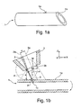
- Fig. 1a shows a tubular workpiece 1, on which a 45 ° portion is formed with a flat sectional surface 1b , which are welded to another (not shown) tubular workpiece with a flat cut surface to form a 90 ° angle along a thin weld connecting the cut surfaces can.
- the flat cut surface 1 b it is necessary to perform on the tubular workpiece 1 a slanted cutting process in which the oblique cutting angle ⁇ (see. Fig. 1b ) is varied in the range between -45 ° and 45 °, since in a conventional cutting process with a constant oblique cutting angle ⁇ , a twisted cut surface would arise on the workpiece 1.
- Fig. 1b shows a snapshot of such a laser beam oblique cutting process on the tubular workpiece 1 at a slanted cutting angle ⁇ of about -20 °, in which a laser cutting beam 2 is aligned with its beam axis 2a with respect to the surface normal to the workpiece surface 1a .
- a laser cutting beam 2 is aligned with its beam axis 2a with respect to the surface normal to the workpiece surface 1a .
- Parallel to the laser cutting beam 2 the nozzle axis 3a of a cutting gas nozzle 3 is aligned, from which a supersonic cutting gas stream 4 emerges and is directed to the workpiece surface 1 a.
- the supersonic cutting gas stream 4 forms a high pressure area 5 on the workpiece surface 1a, which is offset from the nozzle axis 3a of the cutting gas nozzle 3 and its position relative to the nozzle axis 3a in addition to the oblique cutting angle ⁇ and the diameter d of the Schneidgasdüse 3 and the distance a between the edge of the nozzle opening 3b of the cutting gas nozzle 3 and the workpiece surface 1a depends.
- the beam axis 2a of the laser cutting beam 2 and thus also the kerf 1c are offset by a distance (eccentricity) e to the nozzle axis 3a in the laser beam oblique cutting process.
- eccentricity e as a function of the parameters ⁇ , d and a, a simple geometric model based on the law of momentum conservation is used below: The highest pressure and thus the center of the high-pressure region 5 are located where the atoms of the supersonic Cutting gas stream 4 substantially perpendicular to the workpiece surface 1a impinge.
- this position P is defined by the point on the workpiece surface 1 a, which is directly below the center M of the nozzle opening 3b and spaced by a length L thereof on the Workpiece surface 1 a is located.
- the eccentricity e must be determined, which must be set so that the laser cutting beam 2 remains in the high-pressure region 5 when the tubular workpiece 1 under variation of the oblique cutting angle ⁇ along a feed direction Y of an XYZ coordinate system is rotated as in Fig. 1b indicated by an arrow. Such a feed is necessary so that on the tubular workpiece 1 of in Fig. 1a shown, 45 ° section can be generated.
- the position P of the laser cutting beam 2 must be adjusted accordingly so that the laser cutting beam 2 in the high pressure region 5 remains.
- a capacitive distance measuring device 6 may be provided, which as in the cited above EP 1 684 046 A1 or the EP 0 873 813 B1 may be formed, and their operation is not described in detail here.
- the distance measuring device 6 generates a potential difference between the metallic nozzle body of the cutting gas nozzle 3 and the likewise metallic workpiece 1, so that an electric field E is formed between the two whose field lines in FIG FIGS. 2a-c are shown for oblique cutting angle ⁇ of 0 °, 30 ° and 45 °.
- the capacitively measured distance a ' is determined here between the outer edge of the cutting gas nozzle 3 and the workpiece 1, whereas the in Fig. 1b shown distance a between the edge of the nozzle opening 3b and the workpiece 1 is defined. It is understood that with known nozzle geometry of the cutting gas nozzle 3 in the distance measuring device 6, a conversion of the capacitively measured distance a 'in the distance a between the edge of the nozzle opening 3a and the workpiece 1 can be made to use the latter in the above formula.
- the beam axis 2a of the laser cutting beam 2 is aligned at the different oblique cutting angles ⁇ at different distances e to the nozzle axis 3a to keep the cutting gas jet 2 in the high pressure area 5.
- the laser cutting beam 2 is not focused on the workpiece surface 1a, but under it, at a distance of more than 50% of the thickness d of the workpiece 1 from the workpiece top 1a.
- Such a focusing can additionally increase the quality of the cut edges during oblique cutting.
- the focusing can also take place at a distance of more than 70% of the thickness of the workpiece 1 from the workpiece top 1a; Depending on the process conditions, the laser cutting beam 2 can also be focused below the underside of the workpiece 1.
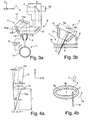
- Fig. 3a shows a section of a laser processing machine 7, which is designed to carry out the method described above on the tubular workpiece 1.
- the laser cutting beam 2 is directed to an adaptive deflecting mirror 8 by means of a beam guide not described in detail and subsequently enters a laser processing head 9 in which a further deflection mirror 10 is arranged, from which the laser cutting beam 2 is deflected into a housing part 11 of the laser processing head is, which is rotatable about an axis parallel to the Y direction by means of a rotating device 11a (see double arrow) in order to set different slanted cutting angle ⁇ on the workpiece 1 can.
- a first and second deflecting mirrors 12a, 12b and a focusing lens 13 for focusing the laser cutting beam 2 on the workpiece 1 and as described above below the workpiece surface 1a.
- the focus position of the laser beam 2 can be changed within certain limits by the adaptive deflecting mirror 8 by suitably changing its shape, for example with the aid of piezoelectric elements or by pressurizing it with a fluid on its rear side.
- the laser processing machine 7 As a movement device for moving the workpiece 1 in the ZY plane, the laser processing machine 7 has a chuck 14 (see arrow), which serves to generate a rotational movement of the workpiece 1, wherein means of the chuck 14th at the same time a movement of the workpiece 1 in the X direction can be done to the in Fig. 1a To produce shown 45 ° section. It is understood that if necessary, the laser processing head 9 can be displaced by means of conventional displacement units in the X direction to the in Fig. 1a shown 45 ° section on the workpiece 1 to produce.
- a displacement device 15 serving as an adjustment device in the form of a conventional linear drive.
- a control device 16 serves to control the displacement device 15 in such a way that the laser cutting gas jet 2 in the X direction at the desired distance to (in Fig. 3 not shown) supersonic cutting gas jet 4 is aligned.
- the above-mentioned formula for the eccentricity e can in this case be stored in the machine control of the laser processing machine 1, so that the control device 16 can calculate the optimum eccentricity itself.
- the laser processing machine 7 of Fig. 3a can also be designed for oblique cutting of a plate-shaped workpiece 1, as in Fig. 3b is shown, in which the feed direction in the X direction.
- the eccentricity e between the laser beam axis 2 and the nozzle axis 3a can be adjusted in the manner described above or otherwise.
- the oblique cutting angle does not necessarily have to be varied during the laser beam cutting. Rather, the oblique cutting angle can also assume a constant value, so that a plane, oblique cutting edge is formed on the workpiece 1.
- the first deflecting mirror 12a may be provided by means of an in Fig. 3 indicated, conventional tilting means 17 are tilted, for example in the form of a piezoelectric actuator so that the laser cutting beam 2 does not impinge perpendicularly, but at an angle ⁇ with respect to the Z direction on the focusing lens 13 and additionally with its laser beam axis 2a with respect to the optical axis 13a of the focusing lens thirteenth impinges on a distance e L offset in the X direction.
- the tilt angle ⁇ required to produce a desired eccentricity e on the workpiece 1 can be determined from the distance between the deflection mirror 12a and the focusing lens 13 and the focal length f by simple geometrical considerations.
- the focusing lens 13 can be tilted in order to obtain the desired lateral offset between the laser cutting beam 2 and the nozzle axis 3a. It is further understood that for oblique focusing not necessarily the generation of a distance e L between the optical axis 13a of the focusing lens 13 and the laser beam axis 2a is required, but that the laser beam axis 2a ideally the focusing lens 13 centrically intersects on the optical axis 13a.
- FIG. 4b Another possibility for generating a lateral offset between laser cutting beam 2 and supersonic cutting gas flow is in Fig. 4b shown by a cutting gas nozzle 3 with elliptical nozzle opening 3b.
- the laser cutting beam 2, behind which forms a cutting gap 18 along the feed direction Y, in this case is not arranged in the center M of the nozzle opening 3b, but laterally offset to this.
- the cutting gas nozzle 3 can in this case by means of a an arrow indicated turning means 19 are rotated about the laser beam axis of the laser cutting beam 2, whereby the position of the center M of the nozzle opening 3b in the X direction changes and also a lateral offset between the laser cutting beam 2 and the center M of the nozzle opening 3b and the supersonic Cutting gas flow results.
- an inert gas for example nitrogen
- a high cutting gas pressure typically more than 10 bar in a (not shown) pressure chamber of the laser cutting head 9, which adjoins the Cutting gas nozzle 3 connects.
- the distance between the cutting gas nozzle 3 and the workpiece surface 1a should be as low as possible in order to obtain optimum cutting results.
- the above-described process for laser beam oblique cutting is largely independent of the machined material and its thickness and can be used in particular for cutting stainless steel, structural steel or aluminum. It is understood that the oblique cutting process is not limited to the cutting of tubular workpieces, but in the manner described above by means of the laser cutting beam any contours, e.g. also be cut on plate-shaped workpieces. In any case, both a high quality of the cut edges produced in the cut section and feed rates can be achieved, which are comparable to those in the vertical laser beam cutting relative to the effective depth of cut.
Landscapes
- Physics & Mathematics (AREA)
- Optics & Photonics (AREA)
- Engineering & Computer Science (AREA)
- Plasma & Fusion (AREA)
- Mechanical Engineering (AREA)
- Laser Beam Processing (AREA)
Description
Die vorliegende Erfindung betrifft ein Verfahren zum Laserstrahlschrägschneiden eines Werkstücks, bei dem ein aus einer Schneidgasdüse austretender Überschall-Schneidgasstrom unter einem Schrägschneidwinkel zur Werkstückoberfläche ausgerichtet wird, und bei dem das Werkstück und der Laserschneidstrahl beim Laserstrahlschrägschneiden relativ zueinander bewegt werden, wobei der Schrägschneidwinkel rechtwinklig zu einer Vorschubrichtung verlauft. Die Erfindung betrifft auch eine Laserbearbeitungsmaschine zum Laserstrahlschrägschneiden eines Werkstücks, umfassend: eine unter einem Schrägschneidwinkel relativ zu einer Werkstückoberfläche ausrichtbare Schneidgasdüse zur Erzeugung eines Überschall-Schneidgasstroms, eine Bewegungseinrichtung zur Bewegung des Werkstücks und des Laserschneidstrahls relativ zueinander unter einem rechtwinklig zu einer Vorschubrichtung verlaufenden Schrägschneidwinkel, und einen Laserbearbeitungskopf zum Positionieren eines Laserschneidstrahls an einer Position auf der Werkstückoberfläche.The present invention relates to a method for laser beam oblique cutting of a workpiece in which a supersonic cutting gas flow emerging from a cutting gas nozzle is aligned at a slant angle to the workpiece surface, and wherein the workpiece and the laser cutting beam are moved relative to each other in the laser beam oblique cutting, the slant angle perpendicular to a Feed direction runs. The invention also relates to a laser processing machine for laser beam oblique cutting of a workpiece, comprising: a cutting gas nozzle which can be oriented at an oblique cutting angle relative to a workpiece surface to produce a supersonic cutting gas stream, a movement device for moving the workpiece and the laser cutting beam relative to each other at an oblique cutting angle at right angles to a feed direction, and a laser processing head for positioning a laser cutting beam at a position on the workpiece surface.
Um zwei insbesondere rohrförmige Werkstücke unter Ausbildung eines Winkels von z.B. 90° miteinander zu verbinden, können diese zunächst schräg unter einem Winkel von 45° abgetrennt und anschließend an den Schnittkanten miteinander verschweißt werden. Für das Schweißen sollten die Schnittkanten möglichst flächig aneinander anliegen, was jedoch nicht möglich ist, wenn der Laserschneidstrahl während des Schneidvorgangs senkrecht zur Flächennormalen der Werkstückoberfläche ausgerichtet ist, da in diesem Fall beim Trennen verwundene Schnittflächen entstehen. Um dies zu vermeiden, wird beim sog. Laserstrahlschrägschneiden der Laserschneidstrahl und der das Laserschneiden unterstützende Überschall-Schneidgasstrom unter einem Winkel zur Flächennormalen geneigt, dem sog. Schrägschneidwinkel. Wird der Schrägschneidwinkel während des Schneidprozesses variiert, kann auch bei einem schrägen Schnitt an einem Rohr eine plane Schnittfläche erzeugt werden, so dass das Verschweißen der Schnittkanten wesentlich vereinfacht wird. Es versteht sich, dass das Schrägschneiden nicht nur an rohrförmigen, sondern auch insbesondere an dicken, plattenförmigen Werkstücken vorgenommen werden kann, um diese an den beim Schrägschneiden gebildeten, schrägen Schnittkanten leichter miteinander verschweißen zu können.To form two, in particular tubular, workpieces with an angle of e.g. 90 ° to connect with each other, they can be initially separated at an angle of 45 ° and then welded together at the cutting edges. For welding, the cut edges should abut each other as flat as possible, but this is not possible if the laser cutting beam is aligned perpendicular to the surface normal of the workpiece surface during the cutting process, since in this case twisted cut surfaces occur during cutting. In order to avoid this, in the so-called laser beam oblique cutting, the laser cutting beam and the supersonic cutting gas stream assisting the laser cutting are inclined at an angle to the surface normal, the so-called oblique cutting angle. If the oblique cutting angle is varied during the cutting process, a planar cut surface can also be produced in the case of an oblique cut on a pipe, so that the welding of the cut edges is considerably simplified. It is understood that the oblique cutting can be made not only on tubular, but also in particular on thick, plate-shaped workpieces in order to weld them easier to each other at the oblique cutting edges formed during oblique cutting.
Der oben beschriebene Laserstrahlschrägschneidprozess ist aber bis jetzt noch keineswegs beherrscht, d.h. es muss mit deutlichen Vorschubsreduzierungen (bei einem Schrägschneidwinkel von 45° bis zu 70%) und deutlichen Qualitätseinbußen gegenüber dem konventionellen Laserstrahlschneiden mit senkrecht zur Werkstückoberfläche ausgerichtetem Laserschneidstrahl gerechnet werden. Insbesondere wiesen die beim Laserstrahlschrägschneiden erzeugten Schnittkanten in Abhängigkeit vom Schrägschneidwinkel unterschiedliche Oberflächengüten auf, wobei an einer Schnittkante eine starke Gratbildung, an der anderen Schnittkante eine raue Oberflächenstruktur zu beobachten ist.However, the above-described laser beam oblique cutting process is far from being mastered, i. It must be expected with significant feed reduction (with a slanted cutting angle of 45 ° to 70%) and significant quality losses compared to conventional laser beam cutting with aligned perpendicular to the workpiece surface laser cutting beam. In particular, the cut edges produced in laser beam oblique cutting showed different surface qualities as a function of the oblique cutting angle, wherein a sharp edge formation is observed at one cut edge and a rough surface structure at the other cut edge.
D2
Aus dem Artikel "
Es ist die Aufgabe der vorliegenden Erfindung, ein Verfahren zum Laserstrahlschrägschneiden sowie eine Laserbearbeitungsmaschine zur Durchführung des Verfahrens dahingehend weiterzubilden, dass ein qualitativ hochwertiger Schnitt bei hohen Vorschubgeschwindigkeiten ermöglicht wird.It is the object of the present invention to develop a method for laser beam oblique cutting as well as a laser processing machine for carrying out the method such that a high-quality cut at high feed speeds is made possible.
Diese Aufgabe wird erfindungsgemäß gelöst durch ein Verfahren der eingangs genannten Art, bei dem während der Relativbewegung die Position des Laserschneidstrahls auf der Werkstückoberfläche so eingestellt wird, dass der Laserschneidstrahl in einem innerhalb des Überschall-Schneidgasstroms gebildeten Hochdruckbereich auf die Werkstückoberfläche auftrifft. Die Position des Hochdruckbereichs innerhalb des Überschall-Schneidgasstroms ist hierbei vom sich ggf. während des Laserschneidens verändernden Schrägschneidwinkel abhängig. Der Hochdruckbereich und damit die Position des Laserschneidstrahls auf der Werkstückoberfläche sind hierbei für Winkel, bei denen der Laserschneidstrahl nicht senkrecht zur Werkstückoberfläche ausgerichtet ist, zur Düsenachse der Schneidgasdüse, welche dem Zentrum des Überschall-Schneidgasstroms entspricht, versetzt.This object is achieved by a method of the type mentioned, in which during the relative movement, the position of the laser cutting beam is set on the workpiece surface so that the laser cutting beam impinges on the workpiece surface in a high pressure area formed within the supersonic cutting gas flow. The position of the high-pressure region within the supersonic cutting gas flow in this case depends on the possibly during laser cutting changing oblique cutting angle. The high-pressure region and thus the position of the laser cutting beam on the workpiece surface are offset for angles at which the laser cutting beam is not aligned perpendicular to the workpiece surface to the nozzle axis of the cutting gas nozzle, which corresponds to the center of supersonic cutting gas flow.
Die Erfinder haben erkannt, dass ein Versatz zwischen Laserschneidstrahl und Zentrum des Überschall-Schneidgasstroms nicht nur bei der Erzeugung von Bohrungen (Trepanieren) günstig ist, sondern auch beim Laserstrahlschrägschneiden, d.h. bei einer Vorschubbewegung zwischen Werkstück und Laserschneidstrahl, da in diesem Fall die Schneidgasdynamik den limitierenden Faktor darstellt: Ein Großteil des Schneidgases strömt an der schräg zum Überschall-Schneidgasstrom verlaufenden Werkstückoberfläche ab und steht somit dem Schneidprozess nicht mehr zur Verfügung, weshalb das hierbei erzeugte statische Druckniveau im Schnittspalt zu gering ist.The inventors have recognized that a misalignment between the laser cutting beam and the center of supersonic cutting gas flow is not only favorable in the production of bores (trephining) but also in the laser beam oblique cutting, i. During a feed movement between the workpiece and the laser cutting beam, since in this case the cutting gas dynamics is the limiting factor: A large part of the cutting gas flows away from the workpiece surface running obliquely to the supersonic cutting gas stream and thus is no longer available for the cutting process, which is why the static pressure level generated in this case in the kerf is too low.
Durch Erzeugen eines gewollten Versatzes (Exzentrizität) zwischen dem Laserschneidgasstrahl und dem Zentrum des Überschall-Schneidgasstroms lässt sich eine Verschiebung des Schnittspalts in einen strömungstechnisch günstigeren Bereich erzielen. Die Verschiebung des Laserschneidstrahls bzw. des Schnittspalts findet dabei rechtwinklig zur Vorschubrichtung und um einen definierten Wert statt, der vom (variablen) Schrägschneidwinkel abhängt. Die auf diese Weise verbesserte Einkopplung des Überschall-Schneidgasstroms in den Schnittspalt hat eine Steigerung des statischen Druckniveaus im Schnittspalt um mehrere Größenordnungen zur Folge. Beispielhafte numerische Strömungsberechnungen ergaben im Vergleich zur bisherigen Verfahrensvariante eine Steigerung um ca. 350%. Eine Erhöhung des statischen Druckniveaus im Schnittspalt hat nachweislich einen verbesserten Schmelzaustrieb zur Folge, was wiederum eine Überhitzung des Schnittspaltes aufgrund des Anstauens von Metallschmelze verhindert. Das so optimierte Austriebsvermögen der Schmelze kann daher direkt in eine Vorschubssteigerung umgewandelt werden. Die maximal erreichten Vorschübe unterscheiden sich hierbei kaum von den blechdickenabhängigen Vorschüben, die beim herkömmlichen Laserstrahlschneiden erreicht werden können. Auch lassen sich an den Schnittkanten auf beiden Seiten Kanten- und Oberflächenqualitäten erzeugen, die mit denjenigen beim senkrechten Laserstrahlschneiden konkurrenzfähig sind.By generating a desired offset (eccentricity) between the laser cutting gas jet and the center of the supersonic cutting gas flow, a displacement of the cutting gap can be achieved in a fluidically favorable area. The displacement of the laser cutting beam or the cutting gap takes place at right angles to the feed direction and by a defined value, which depends on the (variable) oblique cutting angle. The thus improved coupling of supersonic cutting gas flow in the kerf results in an increase of the static pressure level in the kerf by several orders of magnitude result. Exemplary numerical flow calculations resulted in an increase of approximately 350% compared to the previous process variant. Increasing the static pressure level in the kerf has been shown to result in improved melt drainage, which in turn prevents overheating of the kerf due to metal melt build-up. The thus optimized Austriebsvermögen the melt can therefore be converted directly into a feed increase. The maximum feed rates achieved here hardly differ from the sheet-thickness-dependent feeds that can be achieved in conventional laser beam cutting. Also, edge and surface qualities can be produced on the cut edges on both sides, which are competitive with those of vertical laser beam cutting.
Die Variation des Schrägschneidwinkels ist hierbei insbesondere beim Schrägschneiden von Rohren erforderlich, da zur Erzeugung einer ebenen Schnittfläche bei einem 45°-Abschnitt an einem Rohr der Schrägschneidwinkel senkrecht zur Vorschubrichtung z.B. zwischen - 45° und 45° variiert werden muss. Bei rechtwinkliger Ausrichtung des Werkstücks (Schrägschneidwinkel 0°) liegt das Hochdruckgebiet auf dem Werkstück hierbei im Zentrum des Überschall-Schneidgasstroms, bei nicht rechtwinkliger Ausrichtung weist die Position des Hochdruckgebiets davon ab und variiert mit dem Schrägschneidwinkel, so dass die Position des Laserstrahls auf dem Werkstück nachgeführt werden muss, um sicherzustellen, dass der Laserstrahl während des Schrägschneidens im Hochdruckgebiet verbleibt.The variation of the oblique cutting angle is in this case particularly necessary when obliquely cutting pipes, since the oblique cutting angle perpendicular to the feed direction, for example between - 45 ° and 45 ° must be varied to produce a flat cutting surface at a 45 ° section on a pipe. At right angles Orientation of the workpiece (slant cutting angle 0 °) is the high pressure area on the workpiece here in the center of the supersonic cutting gas flow, in non-rectangular orientation, the position of the high pressure area thereof and varies with the slanted cutting angle, so that the position of the laser beam are tracked on the workpiece to ensure that the laser beam remains in the high-pressure area during the oblique cutting.
Laut der Erfindung wird zum Einstellen der Position des Laserschneidsträhls während des Laserstrahlschneidens der Abstand zwischen der Schneidgasdüse und dem Werkstück bestimmt. Der Abstand zwischen Schneidgasdüse und Werkstück ändert sich in der Regel während des Schrägschneidprozesses mit der Veränderung des Schrägschneidwinkels. Da die Position des Hochdruckgebiets auf dem Werkstück auch vom Abstand zwischen Schneidgasdüse und Werkstück abhängt, ist es günstig, den Abstand während des Schrägschneidprozesses möglichst kontinuierlich zu erfassen und den erfassten Abstand zur Einstellung bzw. Anpassung der Position des Laserschneidstrahls zu nutzen.According to the invention, for adjusting the position of the laser cutting line during laser beam cutting, the distance between the cutting gas nozzle and the workpiece is determined. The distance between the cutting gas nozzle and the workpiece usually changes during the oblique cutting process with the change of the oblique cutting angle. Since the position of the high-pressure region on the workpiece also depends on the distance between the cutting gas nozzle and the workpiece, it is favorable to detect the distance as continuously as possible during the oblique cutting process and to use the detected distance for adjusting or adjusting the position of the laser cutting beam.
Laut der Erfindung wird zum Bestimmen des Abstands die Kapazität zwischen Schneidgasdüse und Werkstück gemessen, wobei der Einfluss des Schrägschneidwinkels auf die Kapazität bei der Bestimmung des Abstands berücksichtigt wird. Die kapazitive Messung des Abstandes zwischen Werkstück und Schneidgasdüse ist prinzipiell bekannt und kann wie in der
Laut der Erfindung wird die Position des Laserschneidstrahls in Abhängigkeit vom Abstand a zwischen der Schneidgasdüse und der Werkstückoberfläche sowie dem Durchmesser d der Düsenöffnung bestimmt. Der Abstand e zwischen dem Zentrum des Überschall-Schneidgasstroms und einem parallel zum Überschall-Schneidgasstrom ausgerichteten Laserschneidstrahl, der in seiner idealen Schnittspaltposition in der Mitte des Hochdruckgebietes angeordnet ist, lässt sich in Abhängigkeit der drei Parameter α, a und d wie folgt bestimmen: ![]()
wie weiter unten im Einzelnen dargestellt wird. Da der momentane Schrägschneidwinkel α, der Düsendurchmesser d sowie der Abstand a (ggf. durch eine Abstandsmessung) der Maschinensteuerung bekannt sind, kann eine Laserbearbeitungsmaschine, an der das Verfahren durchgeführt wird, die Exzentrizität e selbst bestimmen und während des Laserstrahlschrägschneidens geeignet anpassen. Insbesondere können hierbei alle benötigten Größen im Maschinencode der numerischen Steuerung ("numerical control") bereits vorgegeben werden. Es versteht sich, dass unter dem Düsendurchmesser nicht notwendiger Weise der Durchmesser einer kreisförmigen Düsenöffnung verstanden wird, sondern dass ggf. auch Schneidgasdüsen mit anderen geometrischen Formen, z.B. mit elliptischer Form der Düsenöffnung eingesetzt werden können. In diesem Fall bezieht sich der Durchmesser der Düsenöffnung auf deren momentane (maximale) Ausdehnung senkrecht zur Vorschubrichtung.According to the invention, the position of the laser cutting beam becomes dependent on the distance a between the cutting gas nozzle and the workpiece surface and the diameter d of the nozzle opening determined. The distance e between the center of the supersonic cutting gas stream and a laser cutting beam oriented parallel to the supersonic cutting gas flow, which is arranged in its ideal cutting gap position in the middle of the high-pressure region, can be determined as a function of the three parameters α, a and d as follows: ![]()
as detailed below. Since the instantaneous slanted cutting angle α, the nozzle diameter d and the distance a (possibly by a distance measurement) of the machine control are known, a laser processing machine, on which the method is performed, determine the eccentricity e itself and adjust it during the laser beam oblique cutting. In particular, all required quantities in the machine code of the numerical control can already be specified here. It is understood that under the nozzle diameter is not necessarily understood the diameter of a circular nozzle opening, but that possibly also cutting gas nozzles can be used with other geometric shapes, eg with an elliptical shape of the nozzle opening. In this case, the diameter of the nozzle opening refers to its momentary (maximum) extent perpendicular to the feed direction.
In einer bevorzugten Variante werden der Laserschneidstrahl und die Düsenachse der Schneidgasdüse parallel ausgerichtet und die Position des Laserschneidstrahls auf der Werkstückoberfläche wird durch Verändern des Abstands zwischen dem Laserschneidstrahl und der Düsenachse eingestellt. Dies kann durch Verschieben des Linsenrohrs mit dem Laserstrahl relativ zur (ortsfesten) Schneidgasdüse, durch Verschieben der Schneidgasdüse beim ortsfestem Laserstrahl oder durch Überlagern dieser beiden Bewegungen erfolgen. In jedem Fall kann zur Bestimmung der Exzentrizität e die obige Formel verwendet werden, wobei diese ggf. noch durch das Hinzufügen von (konstanten) Korrekturfaktoren an die konkreten Prozessbedingungen angepasst werden kann.In a preferred variant, the laser cutting jet and the nozzle axis of the cutting gas nozzle are aligned in parallel and the position of the laser cutting beam on the workpiece surface is adjusted by varying the distance between the laser cutting beam and the nozzle axis. This can be done by moving the lens tube with the laser beam relative to the (fixed) cutting gas nozzle, by moving the cutting gas nozzle at the stationary laser beam or by superimposing these two movements. In any case, the above formula can be used to determine the eccentricity e, whereby this can possibly be adjusted by adding (constant) correction factors to the concrete process conditions.
Bei einer besonders vorteilhaften Variante werden der Laserschneidstrahl und dieIn a particularly advantageous variant, the laser cutting beam and the
Düsenachse der Schneidgasdüse nicht parallel ausgerichtet und bevorzugt wird die Position des Laserschneidstrahls auf der Werkstückoberfläche durch winkelschiefe Fokussierung des Laserschneidstrahls eingestellt. Die Erfinder haben erkannt, dass es nicht zwingend erforderlich ist, den Laserschneidstrahl parallel zur Düsenachse auszurichten bzw. diesen als Ganzes lateral zur Düsenöffnung zu verschieben, um einen Versatz auf der Werkstückoberfläche zu erzeugen. Vielmehr kann der für die vorliegende Anwendung erforderliche, verhältnismäßig geringe Strahlversatz z.B. auch dadurch erreicht werden, dass der Laserschneidstrahl winkelschief fokussiert wird, d.h. der Laserschneidstrahl trifft nicht wie sonst im Wesentlichen senkrecht auf ein fokussierendes Element, sondern seine optische Achse ist bezüglich des fokussierenden Elements geneigt, so dass der Laserschneidstrahl an dem fokussierenden Element umgelenkt wird und sich dadurch ebenfalls eine laterale Verschiebung bezüglich der Düsenachse ergibt.Nozzle axis of the cutting gas nozzle is not aligned parallel and preferably the position of the laser cutting beam is set on the workpiece surface by angular skew focusing of the laser cutting beam. The inventors have recognized that it is not absolutely necessary to align the laser cutting beam parallel to the nozzle axis or to move it as a whole laterally to the nozzle opening in order to produce an offset on the workpiece surface. Rather, the relatively low beam offset required for the present application may be e.g. can also be achieved by focusing the laser cutting beam skewed, i. e. the laser cutting beam does not impinge substantially perpendicular to a focusing element as usual, but its optical axis is inclined with respect to the focusing element, so that the laser cutting beam is deflected at the focusing element and thereby also results in a lateral displacement with respect to the nozzle axis.
In einer bevorzugten Weiterbildung wird zur winkelschiefen Fokussierung des Laserschneidstrahls ein fokussierendes Element und/oder ein im Strahlengang des Laserschneidstrahls vor dem fokussierenden Element angeordneter Umlenkspiegel verkippt. Eine relativ geringe Auslenkung des Umlenkspiegels bzw. des fokussierenden (Linsen-)Elements ist ausreichend, um eine vergleichsweise große Exzentrizität des Laserbearbeitungsstrahls auf dem Werkstück zu erreichen. Insbesondere bei der Verkippung des Umlenkspiegels ist die Verstelleinrichtung hinreichend weit vom eigentlichen Prozess entfernt, so dass dieser störungsunempfindlicher wird.In a preferred refinement, a focusing element and / or a deflecting mirror arranged in the beam path of the laser cutting beam in front of the focusing element are tilted for obliquely oblique focusing of the laser cutting beam. A relatively small deflection of the deflection mirror or the focusing (lens) element is sufficient to achieve a comparatively large eccentricity of the laser processing beam on the workpiece. In particular, in the tilting of the deflection mirror, the adjustment is sufficiently far away from the actual process, so that it is störungsunempfindlicher.
In einer besonders vorteilhaften Variante wird der Laserschneidstrahl in einem Abstand von mehr als 50 %, bevorzugt von mehr als 70 % der Dicke des Werkstücks unterhalb der Werkstückoberseite fokussiert. Die Erfinder haben herausgefunden, dass im Gegensatz zu herkömmlichen Laserschneidprozessen, bei denen der Fokus auf der Werkstückoberfläche oder im oberen Drittel bzw. der oberen Hälfte des Werkstücks fokussiert wird, um einen trichterförmigen Schnittspalt zu erhalten, bei der vorliegenden Anwendung eine Fokussierung in der unteren Hälfte des Werkstücks, ggf. sogar noch unterhalb der Werkstückunterseite günstig ist, um eine hohe Qualität des Laserschneidprozesses zu gewährleisten.In a particularly advantageous variant of the laser cutting beam is focused at a distance of more than 50%, preferably more than 70% of the thickness of the workpiece below the workpiece top. The inventors have found that, in contrast to conventional laser cutting processes in which the focus is focused on the workpiece surface or in the upper third or the upper half of the workpiece to obtain a funnel-shaped kerf, in the present application, a focus in the lower half of the workpiece, possibly even below the bottom of the workpiece is low, to ensure high quality of the laser cutting process.
Als Schneidgas kann ein inertes Gas, insbesondere Stickstoff gewählt werden. Der Überschall-Schneidgasstrom wird in der Regel mit inerten Gasen durchgeführt, d.h. ein zusätzlicher Energieeintrag durch reaktive Gase wie z.B. Sauerstoff findet nicht statt. Das Schneidgas steht hierbei unter einem hohen Druck von mehr als 10 bar, typischer Weise ca. 15 bar, ggf. auch von 20 bar oder mehr.As the cutting gas, an inert gas, in particular nitrogen can be selected. Of the Supersonic cutting gas stream is usually carried out with inert gases, ie an additional energy input by reactive gases such as oxygen does not occur. The cutting gas is under a high pressure of more than 10 bar, typically about 15 bar, possibly even 20 bar or more.
Die Erfindung ist auch verwirklicht in einer Laserbearbeitungsmaschine der eingangs genannten Art, welche zusätzlich aufweist: eine Einstelleinrichtung zum Einstellen der Position des Laserschneidstrahls auf der Werkstückoberfläche relativ zum Überschall-Schneidgasstrom, sowie eine Steuerungseinrichtung, die ausgelegt ist, die Position des Laserschneidstrahls auf der Werkstückoberfläche so einzustellen, dass der Laserschneidstrahl bei der Relativbewegung in einem innerhalb des Überschall-Schneidgasstroms gebildeten Hochdruckgebiet verbleibt. Die Laserberarbeitungsmaschine kann insbesondere zum Laserstrahlschneiden von rohrförmigen Werkstücken ausgelegt sein. Es versteht sich aber, dass ggf. auch ein Schrägschneiden an anderen, insbesondere plattenförmigen Werkstücken erfolgen kann, bei denen der Schrägschneidwinkel ggf. während des Laserstrahlschrägschneidens konstant bleibt.The invention is also realized in a laser processing machine of the aforementioned type, which additionally comprises: adjusting means for adjusting the position of the laser cutting beam on the workpiece surface relative to the supersonic cutting gas flow, and a control means adapted to position the laser cutting beam on the workpiece surface to adjust so that the laser cutting beam during the relative movement remains in a high-pressure area formed within the supersonic cutting gas flow. The laser processing machine can be designed in particular for laser beam cutting of tubular workpieces. However, it is understood that, if appropriate, an oblique cutting can also take place on other, in particular plate-shaped workpieces, in which the oblique cutting angle optionally remains constant during the laser beam oblique cutting.
Laut der Erfindung weist die Laserbearbeitungsmaschine eine Abstandsmesseinrichtung zur Abstandsmessung zwischen der Schneidgasdüse und dem Werkstück auf. Die Abstandsmessung kann z.B. optisch oder mechanisch erfolgen. Mit Hilfe der Abstandsmesseinrichtung kann der Abstand so eingestellt werden, dass er einerseits groß genug ist, um das Berühren der Schneidgasdüse an dem Werkstück bzw. an von diesem abstehenden Teilen zu verhindern, und andererseits klein genug, um eine gute Einkopplung des Schneidgasstrahls in das Werkstück zu ermöglichen.According to the invention, the laser processing machine has a distance measuring device for distance measurement between the cutting gas nozzle and the workpiece. The distance measurement may e.g. optically or mechanically. With the aid of the distance measuring device, the distance can be set such that it is large enough on the one hand to prevent contact between the cutting gas nozzle and the workpiece and on the other hand small enough to ensure good coupling of the cutting gas jet into the workpiece to enable.
Laut der Erfindung ist die Abstandsmesseinrichtung ausgelegt, die Kapazität zwischen der Schneidgasdüse und dem Werkstück zu messen und unter Berücksichtigung des Einflusses des Schrägschneidwinkels auf die Kapazität den Abstand zwischen Schneidgasdüse und Werkstückoberfläche zu bestimmen. Zu diesem Zweck können Kennlinien in der Abstandsmesseinrichtung hinterlegt werden, welche den Zusammenhang zwischen Kapazität und Abstand bei einem jeweiligen Schrägschneidwinkel (z.B. bei 0°, 15°, 30°, 45° etc.) definieren. Die Kennlinien können hierbei durch Kalibrations-Messungen erhalten werden, bei denen der (bekannte) Abstand zwischen Schneidgasdüse und Werkstückoberfläche bei festem Schrägschneidwinkel variiert wird.According to the invention, the distance measuring device is designed to measure the capacitance between the cutting gas nozzle and the workpiece and to determine the distance between the cutting gas nozzle and the workpiece surface, taking into account the influence of the oblique cutting angle on the capacitance. For this purpose, characteristic curves can be stored in the distance measuring device, which define the relationship between capacitance and distance at a respective oblique cutting angle (eg at 0 °, 15 °, 30 °, 45 °, etc.). The Characteristic curves can be obtained by calibration measurements in which the (known) distance between the cutting gas nozzle and the workpiece surface is varied at a fixed oblique cutting angle.
Laut der Erfindung ist die Steuerungseinrichtung ausgelegt, die an den Schrägschneidwinkel angepasste Position des Laserschneidstrahls in Abhängigkeit vom Abstand zwischen der Schneidgasdüse und der Werkstückoberfläche sowie dem Durchmesser der Düsenöffnung zu bestimmen. Dies kann auf besonders einfache Weise durch die oben angegebene Formel erfolgen.According to the invention, the control device is designed to determine the position of the laser cutting beam adapted to the oblique cutting angle as a function of the distance between the cutting gas nozzle and the workpiece surface and the diameter of the nozzle opening. This can be done in a particularly simple manner by the formula given above.
In einer weiteren vorteilhaften Ausführungsform umfasst die Einstelleinrichtung eine Verschiebeeinrichtung zur Einstellung der Position des Laserschneidstrahls auf der Werkstückoberfläche durch Verändern des Abstands zwischen der Düsenachse der Schneidgasdüse und dem parallel zur Düsenachse ausgerichteten LaserschneidStrahl. Als Verschiebeeinrichtung können z.B. Linearmotoren dienen, welche am Laserbearbeitungskopf angebracht sind und die Bewegung der Schneidgasdüse relativ zum Laserbearbeitungskopf entlang einer typischer Weise senkrecht zur Düsenachse ausgerichteten Raumrichtung ermöglichen. Alternativ oder zusätzlich kann auch das Linsenrohr bzw. können optische Elemente, z.B. Umlenkspiegel, in der Strahlführung verschoben oder verkippt werden, um die Position des Laserschneidstrahls in der Düsenöffnung zu verändern und auf diese Weise einen Lateralversatz zwischen Düsenachse und Laserschneidstrahl zu erreichen.In a further advantageous embodiment, the adjusting device comprises a displacement device for adjusting the position of the laser cutting beam on the workpiece surface by changing the distance between the nozzle axis of the cutting gas nozzle and the laser cutting beam aligned parallel to the nozzle axis. As shifter, e.g. Serving linear motors, which are mounted on the laser processing head and allow the movement of the cutting gas nozzle relative to the laser processing head along a direction perpendicular to the nozzle axis aligned spatial direction. Alternatively or additionally, the lens tube or optical elements, e.g. Deflection mirror are moved in the beam guide or tilted to change the position of the laser cutting beam in the nozzle opening and thus to achieve a lateral displacement between the nozzle axis and laser cutting beam.
In einer weiteren vorteilhaften Ausführungsform umfasst die Einstelleinrichtung eine Verkippungseinrichtung zum Verkippen eines fokussierenden Elements und/oder eines im Strahlengang des Laserschneidstrahls vor dem fokussierenden Element angeordneten Umlenkspiegels, um die Position des Laserschneidstrahls auf der Werkstückoberfläche durch winkelschiefe Fokussierung einzustellen. Durch winkelschiefe Fokussierung kann ebenfalls der Strahlversatz bzw. die Exzentrizität des Laserschneidstrahls relativ zum Überschall-Schneidgasstrom auf der Werkstückoberfläche eingestellt werden, wobei in diesem Fall die Düsenachse der Schneidgasdüse und die Strahlachse des Laserschneidstrahls nicht parallel zueinander verlaufen.In a further advantageous embodiment, the adjusting device comprises a tilting device for tilting a focusing element and / or arranged in the beam path of the laser cutting beam in front of the focusing element deflecting mirror to adjust the position of the laser cutting beam on the workpiece surface by angular skew. By skew oblique focus of the jet offset or the eccentricity of the laser cutting beam can be adjusted relative to supersonic cutting gas flow on the workpiece surface, in which case the nozzle axis of the cutting gas nozzle and the beam axis of the laser cutting beam are not parallel.
Es versteht sich, dass neben den oben aufgezeigten Möglichkeiten zur Erzeugung eines lateralen Versatzes zwischen Laserschneidstrahl und Überschall-Schneidgasstrom noch weitere Möglichkeiten bestehen, z.B. kann der Laserschneidstrahl exzentrisch durch eine insbesondere nicht radialsymmetrische Düsenöffnung hindurch treten und durch Drehen des Düsenkörpers ebenfalls ein lateraler Versatz zwischen dem Laserbearbeitungsstrahl und dem Überschall-Schneidgasstrom erzeugt werden.It is understood that in addition to the above-mentioned possibilities for generating a lateral offset between laser cutting jet and supersonic cutting gas flow, there are still further possibilities, e.g. The laser cutting beam can eccentrically pass through a particular non-radially symmetrical nozzle opening and also a lateral offset between the laser processing beam and the supersonic cutting gas flow can be generated by rotating the nozzle body.
Die Erfindung ist weiterhin verwirklicht in einem Computerprogrammprodukt, welches Codemittel zum Erstellen eines Bearbeitungsprogramms aufweist, das zum Durchführen aller Schritte des oben beschriebenen Verfahrens angepasst ist, wenn das Bearbeitungsprogramm auf der Steuerungseinrichtung der Laserbearbeitungsmaschine abläuft. Das Computerprogrammprodukt kann z.B. eine Diskette oder ein anderer Datenträger sein, auf dem ein Programmcode als Codemittel gespeichert ist, der geeignet ist, das Bearbeitungsprogramm anhand von durch einen Benutzer über eine geeignete Bediehoberfläche vorgebbaren Angaben über den gewünschten Schrägschneidprozess (Art des Werkstücks, Art der Kontur, etc.) zu erstellen. Das Bearbeitungsprogramm kann schon lange vor dem Bearbeiten des Werkstückes erstellt werden und erst unmittelbar vor dem Bearbeiten mittels eines computerlesbaren Mediums oder mittels einer anderen Form der Datenübertragung an die Steuerungseinrichtung übermittelt werden.The invention is further embodied in a computer program product having code means for creating a machining program adapted to perform all steps of the above-described method when the machining program runs on the control device of the laser machining machine. The computer program product may e.g. a floppy disk or other data carrier, on which a program code is stored as code means, which is suitable for the processing program on the basis of predetermined by a user on a suitable Bediehoberfläche information about the desired oblique cutting process (type of workpiece, type of contour, etc.) to create. The machining program can be created long before the workpiece is processed and can only be transmitted to the control device by means of a computer-readable medium or by means of another form of data transmission immediately prior to processing.
Weitere Vorteile der Erfindung ergeben sich aus der Beschreibung und der Zeichnung. Ebenso können die vorstehend genannten und die noch weiter aufgeführten Merkmale je für sich oder zu mehreren in beliebigen Kombinationen Verwendung finden. Die gezeigten und beschriebenen Ausführungsformen sind nicht als abschlieβende Aufzählung zu verstehen, sondern haben vielmehr beispielhaften Charakter für die Schilderung der Erfindung.Further advantages of the invention will become apparent from the description and the drawings. Likewise, the features mentioned above and the features listed further can be used individually or in combination in any combination. The embodiments shown and described are not to be understood as exhaustive enumeration, but rather have exemplary character for the description of the invention.
Es zeigen:
- Fign. 1a,b
- eine schematische Darstellung eines rohrförmigen Werkstücks mit einem 45°-Abschnitt mit ebener Schnittfläche (a) und einen erfindungsgemäßen Laserstrahlschrägschneidprozess zur Erzeugung eines solchen Abschnitts mittels eines exzentrisch zu einem Überschall-Schneidgasstrom ausgerichteten Laserschneidstrahl,
- Fign. 2a-c
- schematische Darstellungen der elektrischen Feldstärke zwischen einem Werkstück und einer Schneidgasdüse bei einem Schrägschneidwinkel von 0°, 30° bzw. 45°,
- Fign. 3a,b
- schematische Darstellungen von Teilbereichen einer erfindungsgemäßen Laserbearbeitungsmaschine zur Bearbeitung von rohrförmigen bzw. von plattenförmigen Werkstücken, und
- Fign.4a,b
- schematische Darstellungen der winkelschiefen Fokussierung des Laserschneidstrahls (a) sowie einer drehbaren Schneidgasdüse mit elliptischem Querschnitt (b) jeweils zur Erzeugung eines lateralen Versatzes zwischen Laserschneidstrahl und Überschall-Schneidgasstrom.
- FIGS. 1a, b
- a schematic representation of a tubular workpiece with a 45 ° section with a flat sectional surface (a) and a laser beam oblique cutting process according to the invention for the production of such a section by means of a laser cutting beam aligned eccentrically to a supersonic cutting gas flow,
- FIGS. 2a-c
- schematic representations of the electric field strength between a workpiece and a cutting gas nozzle at a slanted cutting angle of 0 °, 30 ° or 45 °,
- FIGS. 3a, b
- schematic representations of portions of a laser processing machine according to the invention for processing tubular or plate-shaped workpieces, and
- Fign.4a, b
- schematic representations of the oblique focus of the laser cutting beam (a) and a rotatable cutting gas nozzle with elliptical cross-section (b) each for generating a lateral offset between the laser cutting beam and supersonic cutting gas flow.
Um den Laserschneidstrahl 2 im Hochdruckbereich 5 auf der Werkstückoberfläche 1a zu positionieren, wird die Strahlachse 2a des Laserschneidstrahls 2 und damit auch die Schnittfuge 1c bei dem Laserstrahlschrägschneidprozess um einen Abstand (Exzentriziät) e zur Düsenachse 3a versetzt. Zur Bestimmung der Exzentrizität e in Abhängigkeit von den Parametern α, d und a wird im Folgenden ein einfaches geometrisches Modell verwendet, welches auf dem Impulserhaltungssatz basiert: Der höchste Druck und damit die Mitte des Hochdruckgebiets 5 befinden sich dort, wo die Atome des Überschall-Schneidgasstroms 4 im Wesentlichen senkrecht auf die Werkstückoberfläche 1a auftreffen. Geht man davon aus, dass die Gasmoleküle annähernd konzentrisch aus der Düsenöffnung 3b austreten, so ist diese Position P festgelegt durch denjenigen Punkt auf der Werkstückoberfläche 1 a, welcher direkt unterhalb des Mittelpunkts M der Düsenöffnung 3b und um eine Länge L von diesem beabstandet auf der Werkstückoberfläche 1 a liegt.In order to position the
Wie aus ![]()
![]()
Aus obiger Formel kann bei gegebenem, während des gesamten Schrägschneidens konstantem Düsendurchmesser d sowie dem vorgebbaren, variablen Abstand a zwischen Schneidgasdüse 3 und Werkstückoberfläche 1a und dem Schrägschneidwinkel α die Exzentrizität e bestimmt werden, die eingestellt werden muss, damit der Laserschneidstrahl 2 im Hochdruckgebiet 5 verbleibt, wenn das rohrförmige Werkstück 1 unter Variation des Schrägschneidwinkels α entlang einer Vorschubrichtung Y eines XYZ-Koordinatensystems gedreht wird, wie in
Hierzu ist es günstig, den Abstand a zwischen der Scheidgasdüse 3 und dem Werkstück 1 während des Schrägschneidprozesses zu überwachen und ggf. zu regeln. Zu diesem Zweck kann wie in
Wie in
Zur Erzeugung der Exzentrizität des Laserschneidstrahls 2 relativ zur an dem Laserbearbeitungskopf 9 befestigten Schneidgasdüse 3 kann diese mittels einer als Einstelleinrichtung dienenden Verschiebeeinrichtung 15 in Form eines konventionellen Linearantriebs in X-Richtung bewegt werden. Eine Steuerungseinrichtung 16 dient hierbei der Steuerung der Verschiebeeinrichtung 15 auf eine solche Weise, dass der Laserschneidgasstrahl 2 in der X-Richtung im gewünschten Abstand zum (in
Es versteht sich weiterhin, dass die Laserbearbeitungsmaschine 7 von
Es versteht sich weiterhin, dass zur Erzeugung eines Versatzes zwischen der Strahlachse 2a des Laserschneidstrahls 2 und dem Überschall-Schneidgasstrom 4 bzw. der Düsenachse 3a verschiedene Möglichkeiten bestehen, z.B. kann auch durch Verschieben oder Verkippen eines optischen Elements, z.B. der Umlenkspiegel 12a, 12b die gewünschte Exzentrizität e erzeugt werden. Da bei dem Schrägschneidprozess die Laserstrahlachse 2a nicht zwingend parallel zur Düsenachse 3a ausgerichtet sein muss, ist es auch möglich, die Exzentrizität e auf der Werkstückoberfläche 1a durch winkelschiefes Fokussieren an der Fokussierlinse 13 zu erzeugen, wie im Folgenden anhand von
Zur winkelschiefen Fokussierung kann der erste Umlenkspiegel 12a mittels einer in
Eine weitere Möglichkeit zur Erzeugung eines lateralen Versatzes zwischen Laserschneidstrahl 2 und Überschall-Schneidgasstrom ist in
Um geeignete Prozessbedingungen für den Schrägschneidprozess zu erhalten, wird als Schneidgas ein inertes Gas, z.B. Stickstoff, verwendet, das sich unter einem hohen Schneidgasdruck von typischer Weise mehr als 10 bar in einem (nicht gezeigten) Druckraum des Laserschneidkopfs 9 befindet, der sich an die Schneidgasdüse 3 anschließt. Ferner sollte der Abstand zwischen der Schneidgasdüse 3 und der Werkstückoberfläche 1a möglichst gering gewählt werden, um optimale Schneidergebnisse zu erhalten. Weiterhin ist es für das Schrägschneiden bei großen Schrägschneidwinkeln von z.B: 45° günstig, wenn der (Innen-)Durchmesser der Schneidgasdüse 3 groß gewählt wird, z.B. 2 mm oder mehr, wobei wie in
Der oben beschriebene Prozess zum Laserstrahlschrägschneiden ist vom bearbeiteten Material sowie von dessen Dicke weitgehend unabhängig und kann insbesondere zum Schneiden von Edelstahl, Baustahl oder Aluminium eingesetzt werden. Es versteht sich, dass der Schrägschneidprozess nicht auf das Trennschneiden von rohrartigen Werkstücken beschränkt ist, vielmehr können auf die oben beschriebene Weise mittels des Laserschneidstrahls beliebige Konturen z.B. auch an plattenförmigen Werkstücken geschnitten werden. In jedem Fall können sowohl eine hohe Qualität der beim Trennschnitt erzeugten Schnittkanten als auch Vorschubgeschwindigkeiten erreicht werden, die denen beim senkrechten Laserstrahlschneiden bezogen auf die effektive Schnitttiefe vergleichbar sind.The above-described process for laser beam oblique cutting is largely independent of the machined material and its thickness and can be used in particular for cutting stainless steel, structural steel or aluminum. It is understood that the oblique cutting process is not limited to the cutting of tubular workpieces, but in the manner described above by means of the laser cutting beam any contours, e.g. also be cut on plate-shaped workpieces. In any case, both a high quality of the cut edges produced in the cut section and feed rates can be achieved, which are comparable to those in the vertical laser beam cutting relative to the effective depth of cut.
Claims (9)
- Method for oblique laser beam cutting of a workpiece (1), wherein a flow (4) of cutting gas discharged from a cutting gas nozzle (3) is orientated at an oblique cutting angle (α) with respect to the workpiece surface (1a), and wherein the workpiece (1) and the laser cutting beam (2) are moved relative to each other during the oblique laser beam cutting operation, the oblique cutting angle (α) extending perpendicularly relative to a direction of advance (Y),
characterised in that the flow of cutting gas is a supersonic flow of cutting gas, and
that during the relative movement, the offset (e) between the laser cutting beam (2) and the nozzle axis (3a) on the workpiece surface (1a) and thus the position (P) of the laser cutting beam (2) on the workpiece surface (1a) is adjusted in dependence on the oblique cutting angle (α), the distance (a) between the cutting gas nozzle (3) and the workpiece surface (1a) as well as on the diameter (d) of the nozzle opening (3b) such that the laser cutting beam (2) strikes the workpiece surface (1a) in a high-pressure region (5) formed within the supersonic flow (4) of cutting gas, in which high-pressure region the supersonic flow (4) of cutting gas strikes the workpiece surface (1a) substantially perpendicularly, wherein, in order to adjust the position (P) of the laser cutting beam (2), the distance (a) between the cutting gas nozzle (3) and the workpiece (1) is determined during the oblique laser beam cutting operation and in order to determine the distance (a), the capacitance between the cutting gas nozzle (3) and the workpiece (1) is measured, the influence of the oblique cutting angle (α) on the capacitance being taken into account when determining the distance (a). - Method according to claim 1, wherein the laser cutting beam (2) and the nozzle axis (3a) of the cutting gas nozzle (3) are orientated parallel with each other and the position of the laser cutting beam (2) on the workpiece surface (1a) is adjusted by changing the offset (e) between the laser cutting beam (2) and the nozzle axis (3a).
- Method according to any one of the preceding claims, wherein the laser cutting beam (2) and the nozzle axis (3a) of the cutting gas nozzle (3) are not orientated in a parallel manner and the position (P) of the laser cutting beam (2) on the workpiece surface (1a) is preferably adjusted by means of skewed focusing of the laser cutting beam (2).
- Method according to claim 3, wherein, for skewed focusing of the laser cutting beam (2), a focusing element (13) and/or a redirecting mirror (12a) which is arranged upstream of the focusing element (13) in the beam path of the laser cutting beam (2) is tilted.
- Method according to any one of the preceding claims, wherein the laser cutting beam (2) is focused with a distance of more than 50%, preferably more than 70%, of the thickness (D) of the workpiece (1) below the workpiece upper side (1a).
- Laser processing machine (7) for oblique laser beam cutting of a workpiece (1), comprising:a cutting gas nozzle (3) which can be orientated at an oblique cutting angle (α) relative to a workpiece surface (1a) for producing a flow (4) of cutting gas,a movement device (11a, 14) for moving the workpiece (1) and the laser cutting beam (2) relative to each other at an oblique cutting angle (α) which extends perpendicularly relative to a direction of advance (Y), a laser processing head (9) for positioning a laser cutting beam (2) at a position (P) on the workpiece surface (1a),characterised by the cutting gas nozzle which is adapted for generating a supersonic flow of cutting gas,an adjustment device (15, 17, 19) for adjusting the offset (e) between the laser cutting beam (2) and the nozzle axis (3a) on the workpiece surface (1a) and thus the position (P) of the laser cutting beam (2) on the workpiece surface (1a) relative to the supersonic flow (4) of cutting gas, anda control device (16) which is configured to adjust the offset (e) between the laser cutting beam (2) and the nozzle axis (3a) on the workpiece surface (1a) and thus the position (P) of the laser cutting beam (2) on the workpiece surface (1a) in dependence on the oblique cutting angle (α), the distance (a) between the cutting gas nozzle (3) and the workpiece surface (1a) as well as on the diameter (d) of the nozzle opening (3b) such that the laser cutting beam (2) remains in a high-pressure region (5) formed within the supersonic cutting gas flow (4) during the relative movement, in which high-pressure region the supersonic flow (4) of cutting gas strikes the workpiece surface (1a) substantially perpendicularly, further comprising:a distance measuring device (6) for measuring the distance between the cutting gas nozzle (3) and the workpiece (1) which is configured to measure the capacitance between the cutting gas nozzle (3) and the workpiece (1) and to determine the distance (a) taking into account the influence of the oblique cutting angle (α) on the capacitance.
- Laser processing machine according to claim 6, wherein the adjustment device (15, 17, 19) has a displacement device (15) for adjusting the position (P) of the laser cutting beam (2) on the workpiece surface (1a) by changing the offset (e) between the nozzle axis (3a) of the cutting gas nozzle (3) and the laser cutting beam (2) which is orientated parallel with the nozzle axis (3a).
- Laser processing machine according to any one of claims 6 or 7, wherein the adjustment device (15, 17, 19) has a tilting device (17) for tilting a focusing element (13) and/or a redirecting mirror (12a) which is arranged in the beam path of the laser cutting beam (2) upstream of the focusing element (13) in order to adjust the position (P) of the laser cutting beam (2) on the workpiece surface (1a) by means of skewed focusing.
- Computer program product which has encoding means for setting up a processing program, which is adapted to carry out all the steps of the method according to any one of claims 1 to 5, when the processing program is run on the control device (16) of the laser processing machine (7) according to any one of claims 6 to 8.
Applications Claiming Priority (2)
| Application Number | Priority Date | Filing Date | Title |
|---|---|---|---|
| DE102008030783A DE102008030783B3 (en) | 2008-06-28 | 2008-06-28 | Process for laser beam angle cutting of workpiece involving ultrasonic gas cutting stream generally useful in laser cutting operations gives higher quality products at increased cutting speeds |
| PCT/DE2009/000911 WO2009155910A1 (en) | 2008-06-28 | 2009-06-26 | Method for eccentrically orienting a laser cutting beam in relation to a nozzle axis and for cutting at an angle; corresponding laser machining head and laser machining tool |
Publications (2)
| Publication Number | Publication Date |
|---|---|
| EP2310163A1 EP2310163A1 (en) | 2011-04-20 |
| EP2310163B1 true EP2310163B1 (en) | 2014-01-15 |
Family
ID=40847564
Family Applications (2)
| Application Number | Title | Priority Date | Filing Date |
|---|---|---|---|
| EP09768834.5A Active EP2310163B1 (en) | 2008-06-28 | 2009-06-26 | Method for eccentrically orienting a laser cutting beam in relation to a nozzle axis and for cutting at an angle; corresponding laser machining head and laser machining tool |
| EP09768832.9A Active EP2310162B1 (en) | 2008-06-28 | 2009-06-26 | Method of eccentrically orienting a laser cutting beam in relation to a jet axis and for angle cutting ; corresponding laser machining apparatus and computer program |
Family Applications After (1)
| Application Number | Title | Priority Date | Filing Date |
|---|---|---|---|
| EP09768832.9A Active EP2310162B1 (en) | 2008-06-28 | 2009-06-26 | Method of eccentrically orienting a laser cutting beam in relation to a jet axis and for angle cutting ; corresponding laser machining apparatus and computer program |
Country Status (7)
| Country | Link |
|---|---|
| US (2) | US9108271B2 (en) |
| EP (2) | EP2310163B1 (en) |
| JP (2) | JP5575120B2 (en) |
| KR (2) | KR101440671B1 (en) |
| CN (2) | CN102137733B (en) |
| DE (2) | DE102008030783B3 (en) |
| WO (2) | WO2009155908A1 (en) |
Families Citing this family (51)
| Publication number | Priority date | Publication date | Assignee | Title |
|---|---|---|---|---|
| DE102010007323A1 (en) * | 2010-02-08 | 2011-08-11 | Fraunhofer-Gesellschaft zur Förderung der angewandten Forschung e.V., 80686 | Method for determining the cutting result of a laser cutting process |
| DE102010032958A1 (en) | 2010-07-30 | 2012-02-02 | Messer Cutting & Welding Gmbh | Method and device for the thermal processing of a workpiece by means of a laser beam |
| DE202010017944U1 (en) | 2010-08-19 | 2013-03-26 | Trumpf Werkzeugmaschinen Gmbh + Co. Kg | Machine tool for cutting workpieces |
| DE102010039528A1 (en) | 2010-08-19 | 2012-02-23 | Trumpf Werkzeugmaschinen Gmbh + Co. Kg | Capacitive and / or inductive distance measurement |
| DE102011003717A1 (en) | 2011-02-07 | 2012-08-09 | Trumpf Werkzeugmaschinen Gmbh + Co. Kg | Apparatus and method for monitoring and in particular for controlling a laser cutting process |
| CN102319957A (en) * | 2011-09-05 | 2012-01-18 | 沈阳黎明航空发动机(集团)有限责任公司 | A kind of method for laser welding that is applied in the contactor in the harness repairing |
| US9403238B2 (en) * | 2011-09-21 | 2016-08-02 | Align Technology, Inc. | Laser cutting |
| DE102011116974A1 (en) * | 2011-10-26 | 2013-05-02 | Vollmer Werke Maschinenfabrik Gmbh | Device and method for producing a Führungsfase on a workpiece, in particular on a cutting tool |
| DE102011057026B4 (en) * | 2011-12-23 | 2017-11-02 | Acandis Gmbh & Co. Kg | Medical device for insertion into a hollow body organ and manufacturing method |
| JP5981155B2 (en) * | 2012-02-06 | 2016-08-31 | 本田技研工業株式会社 | Metal ring manufacturing method and manufacturing apparatus thereof |
| DE102012102566B4 (en) | 2012-03-26 | 2019-02-21 | Trumpf Werkzeugmaschinen Gmbh + Co. Kg | Transmission element for an adjusting movement of an optical element, positioning and machining head for a laser processing machine |
| CN102615435B (en) * | 2012-04-13 | 2014-10-22 | 中国航空工业集团公司北京航空制造工程研究所 | Method for directly machining turbine blade air film irregular holes through laser |
| CN103406669A (en) * | 2012-04-19 | 2013-11-27 | 中国航空工业集团公司北京航空制造工程研究所 | Method for directly machining turbine blade air film abnormal-shaped hole through laser |
| CN102699541A (en) * | 2012-05-11 | 2012-10-03 | 东莞光谷茂和激光技术有限公司 | Laser cutting process for film coated metal plate |
| EP2682219A1 (en) * | 2012-07-06 | 2014-01-08 | Rollomatic S.A. | Method for workpiece processing |
| CN102922142A (en) * | 2012-10-30 | 2013-02-13 | 张立国 | Method for laser processing |
| JP6378696B2 (en) | 2013-01-30 | 2018-08-22 | コーニング インコーポレイテッド | Apparatus and method for continuous laser cutting of flexible glass |
| CN104096974A (en) * | 2013-04-08 | 2014-10-15 | 昆山允升吉光电科技有限公司 | Laser cutting equipment |
| DE102013008647B4 (en) * | 2013-05-21 | 2019-02-21 | Lt-Ultra Precision Technology Gmbh | Laser processing device with two adaptive mirrors |
| CN103464902B (en) * | 2013-08-21 | 2015-05-13 | 中国航空工业集团公司北京航空制造工程研究所 | Nozzle device for laser rotary cut processing of large-dip-angle aperture and processing method |
| DE102014005562A1 (en) * | 2014-04-15 | 2015-10-15 | H & T Marsberg Gmbh & Co. Kg | Cutting cylindrical hollow body |
| CN104400230A (en) * | 2014-09-27 | 2015-03-11 | 昆山允升吉光电科技有限公司 | Method of using laser cutting device for cutting mask plate |
| CN104353934A (en) * | 2014-09-27 | 2015-02-18 | 昆山允升吉光电科技有限公司 | Spacing rotating laser cutting device |
| WO2016131018A1 (en) | 2015-02-12 | 2016-08-18 | Glowforge Inc. | Visual preview for laser fabrication |
| US10509390B2 (en) | 2015-02-12 | 2019-12-17 | Glowforge Inc. | Safety and reliability guarantees for laser fabrication |
| JP6675420B2 (en) * | 2015-05-13 | 2020-04-01 | バイストロニック レーザー アクチェンゲゼルシャフト | Laser processing equipment |
| KR102587799B1 (en) | 2016-02-12 | 2023-10-10 | 아이피지 포토닉스 코포레이션 | Laser cutting head with dual movable mirrors providing beam alignment and/or rocking movement |
| IT201600070441A1 (en) * | 2016-07-06 | 2018-01-06 | Adige Spa | Process for laser processing of a metal material with high-dynamic control of the axes of movement of the laser beam along a predetermined processing path, as well as a machine and computer program for carrying out such a process. |
| IT201600070259A1 (en) * | 2016-07-06 | 2018-01-06 | Adige Spa | Process of laser processing of a metal material with control of the position of the optical axis of the laser with respect to a flow of assistance gas, as well as a machine and computer program for carrying out such a process. |
| JP6457985B2 (en) * | 2016-08-29 | 2019-01-23 | マニー株式会社 | Medical knife |
| WO2018098397A1 (en) | 2016-11-25 | 2018-05-31 | Glowforge Inc. | Calibration of computer-numerically-controlled machine |
| WO2018098398A1 (en) * | 2016-11-25 | 2018-05-31 | Glowforge Inc. | Preset optical components in a computer numerically controlled machine |
| DE102017207421A1 (en) * | 2017-05-03 | 2018-11-08 | Trumpf Werkzeugmaschinen Gmbh + Co. Kg | Method and distance adjusting device for adjusting the distance of a laser processing head to a workpiece surface and computer program product |
| CN107953038B (en) * | 2017-12-27 | 2023-10-20 | 常州英诺激光科技有限公司 | Transparent brittle material processing equipment |
| DE102018201803A1 (en) * | 2018-02-06 | 2019-08-08 | Technische Universität Dresden | Working head for processing surfaces |
| DE102018206729A1 (en) * | 2018-05-02 | 2019-11-07 | Trumpf Werkzeugmaschinen Gmbh + Co. Kg | Laser processing head and laser processing machine with it |
| US11537098B2 (en) * | 2018-07-06 | 2022-12-27 | Amada Co., Ltd. | Cutting machine and cutting method including tool radius compensation relative to a laser path |
| DE102018129407B4 (en) * | 2018-11-22 | 2023-03-30 | Precitec Gmbh & Co. Kg | Method for cutting a workpiece using a laser beam and a laser processing system for carrying out the method |
| DE102019108172A1 (en) * | 2018-12-19 | 2020-06-25 | Bystronic Laser Ag | NOZZLE CONDITION OR TYPE DETECTION IN A METAL PROCESSING DEVICE |
| DE102019103659B4 (en) * | 2019-02-13 | 2023-11-30 | Bystronic Laser Ag | Gas guide, laser cutting head and laser cutting machine |
| JP7028820B6 (en) * | 2019-03-18 | 2023-12-19 | ファナック株式会社 | Laser processing method for cutting workpieces |
| KR102191836B1 (en) * | 2019-04-30 | 2020-12-18 | 세메스 주식회사 | Apparatus and method for treating substrate |
| WO2020236447A1 (en) | 2019-05-17 | 2020-11-26 | Corning Incorporated | Phase-modified quasi-non-diffracting laser beams for high angle laser processing of transparent workpieces |
| DE102019115174A1 (en) * | 2019-06-05 | 2020-12-10 | Lübbers Anlagen- und Umwelttechnik GmbH | Process for manufacturing a perforated sheet, perforated sheet, molded part and processing device |
| US11858063B2 (en) | 2020-02-03 | 2024-01-02 | Corning Incorporated | Phase-modified quasi-non-diffracting laser beams for high angle laser processing of transparent workpieces |
| US12011781B2 (en) | 2020-06-10 | 2024-06-18 | Corning Incorporated | Phase-modified quasi-non-diffracting laser beams for high angle laser processing of transparent workpieces |
| CN111940911A (en) * | 2020-08-31 | 2020-11-17 | 苏州麦尔科唯激光机器人有限公司 | Optical head device for universal deburring |
| CN112775563B (en) * | 2020-12-18 | 2023-05-05 | 西安晟光硅研半导体科技有限公司 | Unidirectional four-layer bidirectional eight-stage step cutting process for silicon carbide wafer |
| CN114643424A (en) * | 2021-04-25 | 2022-06-21 | 无锡市芯通电子科技有限公司 | Semiconductor chip scribing device convenient to adjust semiconductor chip cutting angle |
| CN114178676A (en) * | 2021-12-02 | 2022-03-15 | 大连理工大学 | Laser-ultrasonic synchronous auxiliary cutting system |
| CN114952026B (en) * | 2022-03-22 | 2024-01-30 | 大族激光科技产业集团股份有限公司 | Groove cutting compensation method, computer readable storage medium and machining device |
Citations (1)
| Publication number | Priority date | Publication date | Assignee | Title |
|---|---|---|---|---|
| JPH0557470A (en) * | 1991-08-31 | 1993-03-09 | Fanuc Ltd | Laser beam processing method and device |
Family Cites Families (56)
| Publication number | Priority date | Publication date | Assignee | Title |
|---|---|---|---|---|
| US3597578A (en) * | 1967-03-16 | 1971-08-03 | Nat Res Dev | Thermal cutting apparatus and method |
| US3965328A (en) * | 1974-12-19 | 1976-06-22 | Avco Corporation | Laser deep cutting process |
| US4205828A (en) * | 1978-08-28 | 1980-06-03 | C-R-O, Inc. | Cutting of contour bevels |
| US4219370A (en) * | 1979-02-21 | 1980-08-26 | Chicago Bridge & Iron Company | Apparatus and method for cutting and beveling pipe ends |
| JPS57100889A (en) | 1980-12-16 | 1982-06-23 | Mitsubishi Electric Corp | Laser working device |
| JPS6040684A (en) * | 1983-08-17 | 1985-03-04 | Mitsubishi Electric Corp | Laser working head |
| DE3339318C2 (en) * | 1983-10-29 | 1995-05-24 | Trumpf Gmbh & Co | Laser processing machine |
| JPS63268585A (en) * | 1986-12-01 | 1988-11-07 | Komatsu Ltd | Cutting method by laser beam |
| DE3807471A1 (en) | 1987-04-02 | 1988-10-20 | Man Technologie Gmbh | DEVICE FOR GUIDING OPTICAL RAYS |
| JPH0199790A (en) * | 1987-10-12 | 1989-04-18 | Mitsubishi Electric Corp | Laser beam cutting method for material easy to stick dross |
| JPH0292485A (en) * | 1988-09-29 | 1990-04-03 | Honda Motor Co Ltd | Laser beam machine and method for adjusting beam axis thereof |
| JP2603873B2 (en) * | 1989-01-09 | 1997-04-23 | 三菱電機株式会社 | Laser processing machine and laser processing method |
| US4972062A (en) | 1989-05-02 | 1990-11-20 | F.I.A. Futurologie Industrielle Automation Gmbh | Laser system |
| JPH0323091A (en) * | 1989-06-20 | 1991-01-31 | Mitsubishi Electric Corp | Laser beam cutting method for material with dross easily stuck |
| JP3083320B2 (en) * | 1991-11-19 | 2000-09-04 | アドバンスド・テクニック・ゲーエムベーハー | Apparatus for removing material from a metal workpiece that is moved relative to a removal tool |
| US5286006A (en) * | 1992-06-29 | 1994-02-15 | Koike Sanso Kogyo Kabushiki Kaisha | Bevel cutting device |
| JP3157294B2 (en) * | 1992-07-28 | 2001-04-16 | 日立建機株式会社 | Laser cutting method and apparatus |
| DE4226620C2 (en) * | 1992-08-12 | 1995-01-19 | Thyssen Stahl Ag | Process for laser beam cutting of strip or plate-shaped workpieces, in particular of electrical sheet |
| US5340962A (en) * | 1992-08-14 | 1994-08-23 | Lumonics Corporation | Automatic control of laser beam tool positioning |
| US5265849A (en) * | 1992-08-19 | 1993-11-30 | Koike Sanso Kogyo Kabushiki Kaisha | Plate cutting device |
| JP3105663B2 (en) * | 1992-10-13 | 2000-11-06 | 株式会社田中製作所 | Method of controlling height of processing head and cutting apparatus using the control method |
| JP2720744B2 (en) * | 1992-12-28 | 1998-03-04 | 三菱電機株式会社 | Laser processing machine |
| JPH06285662A (en) * | 1993-04-07 | 1994-10-11 | Fanuc Ltd | Device and method for laser beam machining |
| JP3285256B2 (en) * | 1993-07-12 | 2002-05-27 | 三洋機工株式会社 | Automatic alignment adjustment method and apparatus for laser robot |
| WO1995008416A1 (en) * | 1993-09-20 | 1995-03-30 | Massachusetts Institute Of Technology | Process for rapidly forming laminated dies and said dies |
| JP2680256B2 (en) * | 1993-12-27 | 1997-11-19 | 川崎重工業株式会社 | Laser processing equipment |
| DE4402000C2 (en) * | 1994-01-25 | 1996-04-11 | Fraunhofer Ges Forschung | Nozzle arrangement for laser beam cutting |
| US5500506A (en) * | 1994-07-13 | 1996-03-19 | Laser Machining, Inc. | Optical system for positioning laser beams in a straight or angular position |
| JPH08141767A (en) * | 1994-11-14 | 1996-06-04 | Mitsubishi Electric Corp | Optical axis adjusting device |
| JPH09150284A (en) | 1995-11-27 | 1997-06-10 | Amada Co Ltd | Method for machining bevel with three dimensional laser beam machine |
| JPH09239577A (en) * | 1996-03-04 | 1997-09-16 | Fanuc Ltd | Working nozzle of laser beam machine |
| GB9611942D0 (en) * | 1996-06-07 | 1996-08-07 | Lumonics Ltd | Focus control of lasers in material processing operations |
| DE19716616C2 (en) * | 1997-04-21 | 2000-08-31 | Trumpf Gmbh & Co | Laser cutting machine and method for laser cutting |
| JPH11197866A (en) * | 1998-01-16 | 1999-07-27 | Fuji Electric Co Ltd | Device for laser beam machining and laser beam cutting method for work |
| JP4118388B2 (en) * | 1998-05-26 | 2008-07-16 | 日酸Tanaka株式会社 | Cutting nozzle and cutting machine |
| DE19835062C1 (en) * | 1998-08-04 | 1999-11-11 | Messer Griesheim Schweistechni | Cutting chamfers on components to be joined by welding |
| DE19835057A1 (en) * | 1998-08-04 | 2000-02-10 | Messer Griesheim Schweistechni | Y-chamfer cutting process |
| DE19860585A1 (en) | 1998-12-29 | 2000-07-20 | Laserpluss Ag | Device for laser-processing workpieces containing diamond |
| JP3730468B2 (en) * | 2000-01-13 | 2006-01-05 | 小池酸素工業株式会社 | Torch angle setting device |
| BE1013404A6 (en) | 2000-04-27 | 2001-12-04 | Dijck Jan Ferdinand Ludovica V | Plasma burner. |
| US6423928B1 (en) * | 2000-10-12 | 2002-07-23 | Ase Americas, Inc. | Gas assisted laser cutting of thin and fragile materials |
| JP4729245B2 (en) * | 2001-05-23 | 2011-07-20 | 三菱電機株式会社 | Laser processing equipment |
| CN2677079Y (en) * | 2003-02-11 | 2005-02-09 | 星云电脑股份有限公司 | Laser processing machine blowing spray nozzle |
| US7074112B2 (en) * | 2003-03-21 | 2006-07-11 | Omax Corporation | Apparatus that holds and tilts a tool |
| DE10321123A1 (en) | 2003-05-09 | 2004-11-25 | Lpkf Laser & Electronics Ag | Device and working method for laser processing |
| CN1281368C (en) * | 2003-06-06 | 2006-10-25 | 中国科学院长春光学精密机械与物理研究所 | Technique for laser cutting metal tube utilizing compressed air and apparatus thereof |
| US7619180B2 (en) * | 2003-06-25 | 2009-11-17 | Reinhard Diem | Laser head of a laser beam processing machine comprising alternating nozzles |
| JP4322575B2 (en) | 2003-06-30 | 2009-09-02 | 日酸Tanaka株式会社 | Laser cutting method and laser cutting apparatus |
| JP4194897B2 (en) * | 2003-07-29 | 2008-12-10 | 新日本工機株式会社 | Laser processing method and laser processing apparatus |
| US6922605B1 (en) * | 2003-10-10 | 2005-07-26 | Omax Corporation | Automated fluid-jet tilt compensation for lag and taper |
| FR2869559B1 (en) | 2004-04-29 | 2007-06-29 | Hubert Clapot | DEVICE FOR CUTTING METAL TUBES |
| EP1632305A1 (en) * | 2004-09-04 | 2006-03-08 | Trumpf Werkzeugmaschinen GmbH + Co. KG | Process for determining and process for adjusting the reciprocal position of the axis of a laser machining beam and the axis of a processing gas jet on a laser working machine as well as laser working machine with equipment for executing the processes |
| PL1684046T3 (en) * | 2005-01-20 | 2008-12-31 | Trumpf Werkzeugmaschinen Gmbh Co Kg | Method and apparatus for measuring the distance between a sensor electrode and a workpiece |
| DE102005027836B4 (en) | 2005-06-10 | 2007-08-02 | Fraunhofer-Gesellschaft zur Förderung der angewandten Forschung e.V. | Apparatus for laser beam cutting |
| JP4792901B2 (en) * | 2005-09-30 | 2011-10-12 | 日産自動車株式会社 | Laser welding apparatus and method, and irradiation apparatus |
| DE102007063627B4 (en) * | 2007-10-02 | 2010-08-12 | Trumpf Werkzeugmaschinen Gmbh + Co. Kg | Method for determining the position of a laser beam relative to an opening, and laser processing machine |
-
2008
- 2008-06-28 DE DE102008030783A patent/DE102008030783B3/en active Active
-
2009
- 2009-06-26 CN CN200980134000.8A patent/CN102137733B/en active Active
- 2009-06-26 KR KR1020117002204A patent/KR101440671B1/en active IP Right Grant
- 2009-06-26 EP EP09768834.5A patent/EP2310163B1/en active Active
- 2009-06-26 KR KR1020117002205A patent/KR101520140B1/en active IP Right Grant
- 2009-06-26 CN CN200980131549.1A patent/CN102123818B/en active Active
- 2009-06-26 WO PCT/DE2009/000891 patent/WO2009155908A1/en active Application Filing
- 2009-06-26 EP EP09768832.9A patent/EP2310162B1/en active Active
- 2009-06-26 JP JP2011515099A patent/JP5575120B2/en active Active
- 2009-06-26 JP JP2011515096A patent/JP5627578B2/en active Active
- 2009-06-26 DE DE112009002160T patent/DE112009002160A5/en not_active Withdrawn
- 2009-06-26 WO PCT/DE2009/000911 patent/WO2009155910A1/en active Application Filing
-
2010
- 2010-12-22 US US12/976,327 patent/US9108271B2/en active Active
- 2010-12-23 US US12/977,308 patent/US9149889B2/en active Active
Patent Citations (1)
| Publication number | Priority date | Publication date | Assignee | Title |
|---|---|---|---|---|
| JPH0557470A (en) * | 1991-08-31 | 1993-03-09 | Fanuc Ltd | Laser beam processing method and device |
Also Published As
| Publication number | Publication date |
|---|---|
| EP2310163A1 (en) | 2011-04-20 |
| EP2310162A1 (en) | 2011-04-20 |
| KR101520140B1 (en) | 2015-05-13 |
| DE112009002160A5 (en) | 2011-06-01 |
| US9108271B2 (en) | 2015-08-18 |
| KR20110038074A (en) | 2011-04-13 |
| DE102008030783B3 (en) | 2009-08-13 |
| JP5627578B2 (en) | 2014-11-19 |
| CN102123818A (en) | 2011-07-13 |
| JP2011526210A (en) | 2011-10-06 |
| KR101440671B1 (en) | 2014-09-23 |
| CN102137733A (en) | 2011-07-27 |
| US20110108533A1 (en) | 2011-05-12 |
| CN102123818B (en) | 2016-08-17 |
| CN102137733B (en) | 2015-07-29 |
| JP2011526211A (en) | 2011-10-06 |
| KR20110038073A (en) | 2011-04-13 |
| JP5575120B2 (en) | 2014-08-20 |
| US20110120982A1 (en) | 2011-05-26 |
| WO2009155910A1 (en) | 2009-12-30 |
| US9149889B2 (en) | 2015-10-06 |
| EP2310162B1 (en) | 2014-08-13 |
| WO2009155908A1 (en) | 2009-12-30 |
Similar Documents
| Publication | Publication Date | Title |
|---|---|---|
| EP2310163B1 (en) | Method for eccentrically orienting a laser cutting beam in relation to a nozzle axis and for cutting at an angle; corresponding laser machining head and laser machining tool | |
| DE102014117157B4 (en) | Method and device for joining workpieces to a lap joint | |
| DE102012100721B3 (en) | Method for controlling a laser cutting process and laser cutting machine | |
| EP2314412B1 (en) | Laser machining apparatus and method for forming a surface on an unfinished product | |
| EP0262363B1 (en) | Process and device for continuously manufacturing tubular articles using longitudinal laser seam welding | |
| EP2691206B1 (en) | Method for machining a workpiece by means of a laser beam | |
| EP4045223B1 (en) | Laser welding method for corner connections of workpiece parts | |
| DE102014203025A1 (en) | Method for laser beam welding and welding head | |
| WO2009021716A1 (en) | Method for joining at least two components by means of laser radiation | |
| EP4200101A1 (en) | Method for producing at least one workpiece part and a residual workpiece from a workpiece | |
| WO2016055184A1 (en) | Method for the laser beam welding of at least two parts to be joined by means of optical seam tracking and a scanner device having superimposed oscillating mirror oscillation | |
| DE102012217766B4 (en) | Method and apparatus for vapor pressure cutting of a metallic workpiece | |
| WO1993023196A1 (en) | Soldering process and device with several high energy soldering beams | |
| WO2022248128A1 (en) | Laser-based deep welding method | |
| EP3880398A1 (en) | Method for splash-free welding, in particular using a solid-state laser | |
| DE102014206358A1 (en) | Method and laser cutting machine for laser cutting small openings | |
| DE202014105648U1 (en) | Device for joining workpieces to a lap joint | |
| DE10162379B4 (en) | Method of making a microbore | |
| DE102016010508A1 (en) | Apparatus, processing apparatus and method for performing a machining process by means of a high-energy machining beam while adjusting the machining beam in accordance with a current processing situation | |
| DE102018127649A1 (en) | Method for laser welding with a stable molten bath and laser processing device | |
| WO2017001098A1 (en) | Apparatus and method for powder-based laser build-up welding | |
| WO2023072568A1 (en) | Method for producing workpiece parts having chamfered cut edges | |
| WO2022184415A1 (en) | Method for monitoring a laser welding process, and associated laser processing machine | |
| EP4031319A1 (en) | Stock feeding device | |
| EP4096860A1 (en) | Assembly for material processing using a laser beam, in particular for laser drilling |
Legal Events
| Date | Code | Title | Description |
|---|---|---|---|
| PUAI | Public reference made under article 153(3) epc to a published international application that has entered the european phase |
Free format text: ORIGINAL CODE: 0009012 |
|
| 17P | Request for examination filed |
Effective date: 20110128 |
|
| AK | Designated contracting states |
Kind code of ref document: A1 Designated state(s): AT BE BG CH CY CZ DE DK EE ES FI FR GB GR HR HU IE IS IT LI LT LU LV MC MK MT NL NO PL PT RO SE SI SK TR |
|
| AX | Request for extension of the european patent |
Extension state: AL BA RS |
|
| 17Q | First examination report despatched |
Effective date: 20110621 |
|
| DAX | Request for extension of the european patent (deleted) | ||
| REG | Reference to a national code |
Ref country code: DE Ref legal event code: R079 Free format text: PREVIOUS MAIN CLASS: B23K0026140000 Ipc: B23K0026380000 |
|
| RIC1 | Information provided on ipc code assigned before grant |
Ipc: B23K 26/14 20060101ALI20130411BHEP Ipc: B23K 26/04 20060101ALI20130411BHEP Ipc: B23K 26/38 20060101AFI20130411BHEP Ipc: B23K 26/03 20060101ALI20130411BHEP |
|
| GRAP | Despatch of communication of intention to grant a patent |
Free format text: ORIGINAL CODE: EPIDOSNIGR1 |
|
| INTG | Intention to grant announced |
Effective date: 20130603 |
|
| RBV | Designated contracting states (corrected) |
Designated state(s): AT BE BG CH CY CZ DK EE ES FI FR GB GR HR HU IE IS IT LI LT LU LV MC MK MT NL NO PL PT RO SE SI SK TR |
|
| REG | Reference to a national code |
Ref country code: DE Ref legal event code: R108 |
|
| GRAP | Despatch of communication of intention to grant a patent |
Free format text: ORIGINAL CODE: EPIDOSNIGR1 |
|
| INTG | Intention to grant announced |
Effective date: 20130807 |
|
| REG | Reference to a national code |
Ref country code: DE Ref legal event code: R108 Effective date: 20130717 |
|
| GRAS | Grant fee paid |
Free format text: ORIGINAL CODE: EPIDOSNIGR3 |
|
| GRAA | (expected) grant |
Free format text: ORIGINAL CODE: 0009210 |
|
| AK | Designated contracting states |
Kind code of ref document: B1 Designated state(s): AT BE BG CH CY CZ DK EE ES FI FR GB GR HR HU IE IS IT LI LT LU LV MC MK MT NL NO PL PT RO SE SI SK TR |
|
| REG | Reference to a national code |
Ref country code: CH Ref legal event code: EP Ref country code: GB Ref legal event code: FG4D Free format text: NOT ENGLISH |
|
| REG | Reference to a national code |
Ref country code: AT Ref legal event code: REF Ref document number: 649573 Country of ref document: AT Kind code of ref document: T Effective date: 20140215 |
|
| REG | Reference to a national code |
Ref country code: IE Ref legal event code: FG4D Free format text: LANGUAGE OF EP DOCUMENT: GERMAN |
|
| REG | Reference to a national code |
Ref country code: NL Ref legal event code: VDEP Effective date: 20140115 |
|
| REG | Reference to a national code |
Ref country code: LT Ref legal event code: MG4D |
|
| PG25 | Lapsed in a contracting state [announced via postgrant information from national office to epo] |
Ref country code: NO Free format text: LAPSE BECAUSE OF FAILURE TO SUBMIT A TRANSLATION OF THE DESCRIPTION OR TO PAY THE FEE WITHIN THE PRESCRIBED TIME-LIMIT Effective date: 20140415 Ref country code: LT Free format text: LAPSE BECAUSE OF FAILURE TO SUBMIT A TRANSLATION OF THE DESCRIPTION OR TO PAY THE FEE WITHIN THE PRESCRIBED TIME-LIMIT Effective date: 20140115 Ref country code: IS Free format text: LAPSE BECAUSE OF FAILURE TO SUBMIT A TRANSLATION OF THE DESCRIPTION OR TO PAY THE FEE WITHIN THE PRESCRIBED TIME-LIMIT Effective date: 20140515 |
|
| PG25 | Lapsed in a contracting state [announced via postgrant information from national office to epo] |
Ref country code: SE Free format text: LAPSE BECAUSE OF FAILURE TO SUBMIT A TRANSLATION OF THE DESCRIPTION OR TO PAY THE FEE WITHIN THE PRESCRIBED TIME-LIMIT Effective date: 20140115 Ref country code: NL Free format text: LAPSE BECAUSE OF FAILURE TO SUBMIT A TRANSLATION OF THE DESCRIPTION OR TO PAY THE FEE WITHIN THE PRESCRIBED TIME-LIMIT Effective date: 20140115 Ref country code: ES Free format text: LAPSE BECAUSE OF FAILURE TO SUBMIT A TRANSLATION OF THE DESCRIPTION OR TO PAY THE FEE WITHIN THE PRESCRIBED TIME-LIMIT Effective date: 20140115 Ref country code: CY Free format text: LAPSE BECAUSE OF FAILURE TO SUBMIT A TRANSLATION OF THE DESCRIPTION OR TO PAY THE FEE WITHIN THE PRESCRIBED TIME-LIMIT Effective date: 20140115 Ref country code: FI Free format text: LAPSE BECAUSE OF FAILURE TO SUBMIT A TRANSLATION OF THE DESCRIPTION OR TO PAY THE FEE WITHIN THE PRESCRIBED TIME-LIMIT Effective date: 20140115 Ref country code: PT Free format text: LAPSE BECAUSE OF FAILURE TO SUBMIT A TRANSLATION OF THE DESCRIPTION OR TO PAY THE FEE WITHIN THE PRESCRIBED TIME-LIMIT Effective date: 20140515 |
|
| PG25 | Lapsed in a contracting state [announced via postgrant information from national office to epo] |
Ref country code: LV Free format text: LAPSE BECAUSE OF FAILURE TO SUBMIT A TRANSLATION OF THE DESCRIPTION OR TO PAY THE FEE WITHIN THE PRESCRIBED TIME-LIMIT Effective date: 20140115 Ref country code: HR Free format text: LAPSE BECAUSE OF FAILURE TO SUBMIT A TRANSLATION OF THE DESCRIPTION OR TO PAY THE FEE WITHIN THE PRESCRIBED TIME-LIMIT Effective date: 20140115 |
|
| PG25 | Lapsed in a contracting state [announced via postgrant information from national office to epo] |
Ref country code: RO Free format text: LAPSE BECAUSE OF FAILURE TO SUBMIT A TRANSLATION OF THE DESCRIPTION OR TO PAY THE FEE WITHIN THE PRESCRIBED TIME-LIMIT Effective date: 20140115 Ref country code: DK Free format text: LAPSE BECAUSE OF FAILURE TO SUBMIT A TRANSLATION OF THE DESCRIPTION OR TO PAY THE FEE WITHIN THE PRESCRIBED TIME-LIMIT Effective date: 20140115 Ref country code: EE Free format text: LAPSE BECAUSE OF FAILURE TO SUBMIT A TRANSLATION OF THE DESCRIPTION OR TO PAY THE FEE WITHIN THE PRESCRIBED TIME-LIMIT Effective date: 20140115 |
|
| PLBE | No opposition filed within time limit |
Free format text: ORIGINAL CODE: 0009261 |
|
| STAA | Information on the status of an ep patent application or granted ep patent |
Free format text: STATUS: NO OPPOSITION FILED WITHIN TIME LIMIT |
|
| PG25 | Lapsed in a contracting state [announced via postgrant information from national office to epo] |
Ref country code: PL Free format text: LAPSE BECAUSE OF FAILURE TO SUBMIT A TRANSLATION OF THE DESCRIPTION OR TO PAY THE FEE WITHIN THE PRESCRIBED TIME-LIMIT Effective date: 20140115 Ref country code: SK Free format text: LAPSE BECAUSE OF FAILURE TO SUBMIT A TRANSLATION OF THE DESCRIPTION OR TO PAY THE FEE WITHIN THE PRESCRIBED TIME-LIMIT Effective date: 20140115 |
|
| 26N | No opposition filed |
Effective date: 20141016 |
|
| PG25 | Lapsed in a contracting state [announced via postgrant information from national office to epo] |
Ref country code: MC Free format text: LAPSE BECAUSE OF FAILURE TO SUBMIT A TRANSLATION OF THE DESCRIPTION OR TO PAY THE FEE WITHIN THE PRESCRIBED TIME-LIMIT Effective date: 20140115 Ref country code: LU Free format text: LAPSE BECAUSE OF FAILURE TO SUBMIT A TRANSLATION OF THE DESCRIPTION OR TO PAY THE FEE WITHIN THE PRESCRIBED TIME-LIMIT Effective date: 20140626 |
|
| GBPC | Gb: european patent ceased through non-payment of renewal fee |
Effective date: 20140626 |
|
| REG | Reference to a national code |
Ref country code: IE Ref legal event code: MM4A |
|
| PG25 | Lapsed in a contracting state [announced via postgrant information from national office to epo] |
Ref country code: IE Free format text: LAPSE BECAUSE OF NON-PAYMENT OF DUE FEES Effective date: 20140626 |
|
| PG25 | Lapsed in a contracting state [announced via postgrant information from national office to epo] |
Ref country code: SI Free format text: LAPSE BECAUSE OF FAILURE TO SUBMIT A TRANSLATION OF THE DESCRIPTION OR TO PAY THE FEE WITHIN THE PRESCRIBED TIME-LIMIT Effective date: 20140115 Ref country code: GB Free format text: LAPSE BECAUSE OF NON-PAYMENT OF DUE FEES Effective date: 20140626 |
|
| REG | Reference to a national code |
Ref country code: AT Ref legal event code: MM01 Ref document number: 649573 Country of ref document: AT Kind code of ref document: T Effective date: 20140626 |
|
| PG25 | Lapsed in a contracting state [announced via postgrant information from national office to epo] |
Ref country code: AT Free format text: LAPSE BECAUSE OF NON-PAYMENT OF DUE FEES Effective date: 20140626 |
|
| PG25 | Lapsed in a contracting state [announced via postgrant information from national office to epo] |
Ref country code: MT Free format text: LAPSE BECAUSE OF FAILURE TO SUBMIT A TRANSLATION OF THE DESCRIPTION OR TO PAY THE FEE WITHIN THE PRESCRIBED TIME-LIMIT Effective date: 20140115 |
|
| REG | Reference to a national code |
Ref country code: FR Ref legal event code: PLFP Year of fee payment: 8 |
|
| PG25 | Lapsed in a contracting state [announced via postgrant information from national office to epo] |
Ref country code: BG Free format text: LAPSE BECAUSE OF FAILURE TO SUBMIT A TRANSLATION OF THE DESCRIPTION OR TO PAY THE FEE WITHIN THE PRESCRIBED TIME-LIMIT Effective date: 20140115 Ref country code: GR Free format text: LAPSE BECAUSE OF FAILURE TO SUBMIT A TRANSLATION OF THE DESCRIPTION OR TO PAY THE FEE WITHIN THE PRESCRIBED TIME-LIMIT Effective date: 20140416 |
|
| PG25 | Lapsed in a contracting state [announced via postgrant information from national office to epo] |
Ref country code: HU Free format text: LAPSE BECAUSE OF FAILURE TO SUBMIT A TRANSLATION OF THE DESCRIPTION OR TO PAY THE FEE WITHIN THE PRESCRIBED TIME-LIMIT; INVALID AB INITIO Effective date: 20090626 Ref country code: TR Free format text: LAPSE BECAUSE OF FAILURE TO SUBMIT A TRANSLATION OF THE DESCRIPTION OR TO PAY THE FEE WITHIN THE PRESCRIBED TIME-LIMIT Effective date: 20140115 Ref country code: BE Free format text: LAPSE BECAUSE OF FAILURE TO SUBMIT A TRANSLATION OF THE DESCRIPTION OR TO PAY THE FEE WITHIN THE PRESCRIBED TIME-LIMIT Effective date: 20140630 |
|
| REG | Reference to a national code |
Ref country code: FR Ref legal event code: PLFP Year of fee payment: 9 |
|
| REG | Reference to a national code |
Ref country code: FR Ref legal event code: PLFP Year of fee payment: 10 |
|
| PG25 | Lapsed in a contracting state [announced via postgrant information from national office to epo] |
Ref country code: MK Free format text: LAPSE BECAUSE OF FAILURE TO SUBMIT A TRANSLATION OF THE DESCRIPTION OR TO PAY THE FEE WITHIN THE PRESCRIBED TIME-LIMIT Effective date: 20140115 |
|
| PGFP | Annual fee paid to national office [announced via postgrant information from national office to epo] |
Ref country code: FR Payment date: 20210622 Year of fee payment: 13 |
|
| PGFP | Annual fee paid to national office [announced via postgrant information from national office to epo] |
Ref country code: CH Payment date: 20210618 Year of fee payment: 13 |
|
| PGFP | Annual fee paid to national office [announced via postgrant information from national office to epo] |
Ref country code: CZ Payment date: 20210628 Year of fee payment: 13 |
|
| PG25 | Lapsed in a contracting state [announced via postgrant information from national office to epo] |
Ref country code: CZ Free format text: LAPSE BECAUSE OF NON-PAYMENT OF DUE FEES Effective date: 20220626 |
|
| REG | Reference to a national code |
Ref country code: CH Ref legal event code: PL |
|
| PG25 | Lapsed in a contracting state [announced via postgrant information from national office to epo] |
Ref country code: LI Free format text: LAPSE BECAUSE OF NON-PAYMENT OF DUE FEES Effective date: 20220630 Ref country code: FR Free format text: LAPSE BECAUSE OF NON-PAYMENT OF DUE FEES Effective date: 20220630 Ref country code: CH Free format text: LAPSE BECAUSE OF NON-PAYMENT OF DUE FEES Effective date: 20220630 |
|
| PGFP | Annual fee paid to national office [announced via postgrant information from national office to epo] |
Ref country code: IT Payment date: 20230623 Year of fee payment: 15 |