EP2301485B1 - Brustprothese - Google Patents
Brustprothese Download PDFInfo
- Publication number
- EP2301485B1 EP2301485B1 EP10003996.5A EP10003996A EP2301485B1 EP 2301485 B1 EP2301485 B1 EP 2301485B1 EP 10003996 A EP10003996 A EP 10003996A EP 2301485 B1 EP2301485 B1 EP 2301485B1
- Authority
- EP
- European Patent Office
- Prior art keywords
- breast prosthesis
- latent heat
- nubs
- accordance
- heat store
- Prior art date
- Legal status (The legal status is an assumption and is not a legal conclusion. Google has not performed a legal analysis and makes no representation as to the accuracy of the status listed.)
- Active
Links
Images
Classifications
-
- A—HUMAN NECESSITIES
- A61—MEDICAL OR VETERINARY SCIENCE; HYGIENE
- A61F—FILTERS IMPLANTABLE INTO BLOOD VESSELS; PROSTHESES; DEVICES PROVIDING PATENCY TO, OR PREVENTING COLLAPSING OF, TUBULAR STRUCTURES OF THE BODY, e.g. STENTS; ORTHOPAEDIC, NURSING OR CONTRACEPTIVE DEVICES; FOMENTATION; TREATMENT OR PROTECTION OF EYES OR EARS; BANDAGES, DRESSINGS OR ABSORBENT PADS; FIRST-AID KITS
- A61F2/00—Filters implantable into blood vessels; Prostheses, i.e. artificial substitutes or replacements for parts of the body; Appliances for connecting them with the body; Devices providing patency to, or preventing collapsing of, tubular structures of the body, e.g. stents
- A61F2/50—Prostheses not implantable in the body
- A61F2/52—Mammary prostheses
-
- A—HUMAN NECESSITIES
- A61—MEDICAL OR VETERINARY SCIENCE; HYGIENE
- A61F—FILTERS IMPLANTABLE INTO BLOOD VESSELS; PROSTHESES; DEVICES PROVIDING PATENCY TO, OR PREVENTING COLLAPSING OF, TUBULAR STRUCTURES OF THE BODY, e.g. STENTS; ORTHOPAEDIC, NURSING OR CONTRACEPTIVE DEVICES; FOMENTATION; TREATMENT OR PROTECTION OF EYES OR EARS; BANDAGES, DRESSINGS OR ABSORBENT PADS; FIRST-AID KITS
- A61F2/00—Filters implantable into blood vessels; Prostheses, i.e. artificial substitutes or replacements for parts of the body; Appliances for connecting them with the body; Devices providing patency to, or preventing collapsing of, tubular structures of the body, e.g. stents
- A61F2/50—Prostheses not implantable in the body
- A61F2/5044—Designing or manufacturing processes
- A61F2002/5056—Laminates, i.e. layered products
-
- A—HUMAN NECESSITIES
- A61—MEDICAL OR VETERINARY SCIENCE; HYGIENE
- A61F—FILTERS IMPLANTABLE INTO BLOOD VESSELS; PROSTHESES; DEVICES PROVIDING PATENCY TO, OR PREVENTING COLLAPSING OF, TUBULAR STRUCTURES OF THE BODY, e.g. STENTS; ORTHOPAEDIC, NURSING OR CONTRACEPTIVE DEVICES; FOMENTATION; TREATMENT OR PROTECTION OF EYES OR EARS; BANDAGES, DRESSINGS OR ABSORBENT PADS; FIRST-AID KITS
- A61F2/00—Filters implantable into blood vessels; Prostheses, i.e. artificial substitutes or replacements for parts of the body; Appliances for connecting them with the body; Devices providing patency to, or preventing collapsing of, tubular structures of the body, e.g. stents
- A61F2/50—Prostheses not implantable in the body
- A61F2/52—Mammary prostheses
- A61F2002/523—Multiple breast forms made of several concentric breast-shaped layers nested into one another
Definitions
- the present invention relates to a breast prosthesis having at least one support surface intended for support on a body surface.
- breast prostheses for the care of patients after breast surgery, especially after mastectomies are already known. Such breast prostheses are usually placed directly on the body surface and dwell there partly over a longer period, especially over the entire day.
- Direct contact with the surface of the body can cause problems in terms of wearing comfort.
- a breast prosthesis has at least one support surface which is intended for support on a body surface, wherein the support surface has a plurality of formations in the form of nubs, which raise at different heights from the support surface, wherein the height of the knobs decreases towards the edges of the support surface, and wherein by means of the knobs, an air circulation and / or air exchange between support surface and body surface can be achieved.
- the nubs or nubs are elliptical and / or round and / or teardrop-shaped.
- An embodiment of the dimples can take place, for example, by providing a dimpled cavity or shape with or without a vacuum for forming the prosthesis blank during the production process. It is also conceivable to provide a separate mold, such as a nubbed shell, which can be placed on already used cavities or forms (cosmetic layer membrane cavity / template). It is conceivable to use 3D injection molding for the production or to apply the studded moldings one by one.
- knobs can be subsequently applied to a standard blank for a breast prosthesis, such as by caterpillar dosing. It is also possible to foam the nubs, for example by integral foam and / or thermoplastic foam.
- thermal activation can be achieved by infrared, high frequency, heating templates or lasers.
- Another possibility is to rake the knobs from a hard back, so provide about a hard silicone plate for the support surface from which the knobs and the support surface formed, in particular milled.
- the size of the dimples decreases at least to one edge, preferably in each case to all edges, and is preferably greatest in the middle region of the support surface.
- knobs are provided, which are arranged on the support surface, that at least one air duct are formed by the arrangement in the mounted state on the body surface, by means of which air is supplied and discharged.
- the breast prosthesis has at least one latent heat storage or at least partially made of latent heat storage material, the latent heat storage or the latent heat storage material is preferably PCM material. Material is preferably used as the latent heat storage or as latent heat storage material whose melting point is in the range of body temperature, so that excess heat energy is absorbed by the ongoing phase transition of the solid into the liquid phase of the latent heat storage or the latent heat storage material.
- the latent heat storage or the latent heat storage material is arranged in the region of the support surface.
- the latent heat storage or the latent heat storage material is arranged in the region of the agent.
- optimizing the effect of the PCM material can be achieved by the nub structure in combination with a PCM material by rapidly reacting with skin contact areas, later use additional areas in the center of the nub by heat conduction and the areas at the nubs approach on air circulation react for a longer time.
- a buffer effect can thus be advantageously achieved.
- the effect of the PCM material can be more developed or better utilized by the increased surface area. A significantly improved wearing comfort, prevention of overheating and an improvement of the microclimate can be advantageously achieved.
- the nubs, at least partially by the latent heat storage or the latent heat storage material is / are formed and / or at least partially the latent heat storage or the latent heat storage material comprises or include.
- the breast prosthesis consists at least partially of an addition-crosslinking two-component silicone rubber compound or comprises an addition-crosslinking two-component silicone rubber compound.
- the breast prosthesis is formed of at least one mass welded into plastic film and / or the breast shape is simulated, wherein the mass preferably consists at least partially of an addition-crosslinking two-component silicone rubber mass and / or that the breast prosthesis consists of a cup-shaped body a soft-elastic plastic, preferably an addition-crosslinked two-component silicone rubber compound, which is welded in plastic films and thus forms a first chamber, and one of the wearer during wear facing and adjoining the first chamber with a filler fillable second chamber.
- polyurethane films can be used as plastic films.
- the molding is formed by a mass welded in plastic film, the composition preferably consisting at least partially of an addition-crosslinking two-component silicone rubber compound.
- the breast prosthesis and / or the knobs are or are at least partially made of foam.
- the knobs are made of foam. It is also possible that rise from the support surface Schaumstoffwulste.
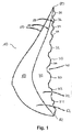
- FIG. 1 shows a sectional view of the breast prosthesis 10 in a first embodiment in side view.
- the breast prosthesis 10 is modeled on the shape of a female breast and can be designed as a right or left breast prosthesis. It is equally conceivable that a single embodiment of the breast prosthesis 10 is provided for the right or left side.
- the breast prosthesis 10 is triangular in the front view and has convex outer edges or edges 80, 82, 84.
- the breast prosthesis 10 has two chambers 60 and 70, the first chamber 60 facing away from the support surface 20 and being formed or bounded by two foils 50.
- the foils 50 are polyurethane foils 50.
- the Chamber 60 filled with an addition-crosslinked two-component silicone rubber mass 62.
- the second chamber 70 is internal, d. H. an outer surface 20 of the chamber 70 is a support surface 20 which is intended for resting on the body surface.
- the chamber 70 is also delimited by two foils 50, the foil 50 lying inside the breast prosthesis 10 separating the chambers 60 and 70 from one another.
- the chamber 70 is preferably filled with latent heat storage material 72, in particular PCM material 72.
- the means 30, 32, 34, 36 rise, by means of which an air circulation and an air exchange between the support surface 20 and the body surface (not in FIG. 1 shown) is achievable.
- the means 30, 32, 34, 36 are designed as nubs 30, 32, 34, 36, which rise from the support surface 20, so that between the nubs 30, 32, 34, 36 air ducts 40 are formed, the air circulation allow between support surface 20 and body surface.
- the nubs 30, 32, 34, 36 are formed by the shape of the chamber 70, such as by the shape of the surrounded by the film 50 latent heat storage material 72. Just as well, however, can also be provided that the nubs 30, 32, 34, 36 on the support surface 20 and the film 50 are placed separately.
- the height and also the size of the knobs 30, 32, 34, 36 decreases in each case to the edges 80, 82, so the upper edge 80 and the lower edge 82 of the support surface 20 from, preferably also to those not in FIG. 1
- the side knobs 30, 32, 34, 36 are preferably formed circular in relation to the cross section and rise in a hemispherical shape from the support surface 20th
- the knobs 30 in the first and largest height and size are arranged in the center of the support surface 20 and surrounded by the knobs 32 in the second and next smaller size and height. This is followed by the nubs 34 and 36 in the third and fourth, each decreasing in height and size.
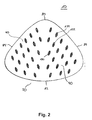
- FIG. 2 shows a rear view of another embodiment of the breast prosthesis 10 with a view of the support surface 20.
- a plurality of oval or elliptical knobs 130, 132, 134 which rise at different heights from the support surface 20 and between which intermediate spaces 40 are present are that serve for air circulation and air exchange.
- the height of the nubs 130, 132, 134 decreases in each case to the edges 80, 82, 84, ie to the upper edge 80 and the lower edge 82 and to the side edges 84 of the support surface 20 from.
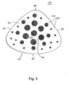
- FIG. 3 shows a rear view of another embodiment of the breast prosthesis 10 with a view of the support surface 20.
- From the support surface 20 rise several circular 230, 232, 234, which rise in several heights and sizes from the support surface 20 approximately hemispherical and between which intermediate spaces 40 are provided, which are used for air circulation and air exchange.
- the height and size of the dimples 230, 232, 234 decreases in each case to the edges 80, 82, 84, ie to the upper edge 80 and the lower edge 82 and to the side edges 84 of the support surface 20.
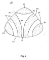
- FIG. 4 shows a rear view of another embodiment of the breast prosthesis 10 with a view of the support surface 20, wherein the means 330, 332 to achieve an air exchange between support surface 20 and the body surface as foam formations 330, 332 are formed.
- the formations 330, 332 rise from the bearing surface 20, wherein the lying on the side edges 80, 82, 84 and in the corner regions formations 332 have a lower height than the formations 330, which are arranged centrally in the support surface 20.
- the bead-like formations 330 also decrease in height in the areas adjacent to the edges 82, 82.
- Between the formations 330, 332 are intermediate spaces 40 and air passages 40, through which an air exchange is made possible.
- an approximately triangular gap 40 is formed, which has concave sides.
Landscapes
- Health & Medical Sciences (AREA)
- Cardiology (AREA)
- Oral & Maxillofacial Surgery (AREA)
- Transplantation (AREA)
- Engineering & Computer Science (AREA)
- Biomedical Technology (AREA)
- Heart & Thoracic Surgery (AREA)
- Vascular Medicine (AREA)
- Life Sciences & Earth Sciences (AREA)
- Animal Behavior & Ethology (AREA)
- General Health & Medical Sciences (AREA)
- Public Health (AREA)
- Veterinary Medicine (AREA)
- Prostheses (AREA)
- Corsets Or Brassieres (AREA)
Description
- Die vorliegende Erfindung betrifft eine Brustprothese mit wenigstens einer Auflagefläche, die für die Auflage auf einer Körperoberfläche bestimmt ist.
- Brustprothesen für die Versorgung von Patientinnen nach Brustoperationen, insbesondere nach Brustamputationen sind bereits bekannt. Derartige Brustprothesen werden üblicherweise direkt auf die Körperoberfläche aufgelegt und verweilen dort teilweise über einen längeren Zeitraum, insbesondere über den gesamten Tag.
- Durch die direkte Auflage auf der Körperoberfläche können sich Probleme hinsichtlich des Tragekomforts ergeben. Insbesondere ist es möglich, dass es zur Schweißbildung, aber auch Überwärmung des Bereiches der Körperoberfläche kommt, auf dem die Brustprothese aufliegt. Dies wird von den Nutzerinnen als unangenehm empfunden. Darüber hinaus kann es auch zu Reizungen der Haut kommen, was ebenfalls unerwünscht ist.
- Ein Vorschlag zur Beseitigung der vorgenannten Probleme besteht darin, die dem Körper zugewandte Seite der Brustprothese als Latentwärmespeicher auszubilden, mittels dem überschüssige Wärme beseitigt werden soll. In entsprechend auf dem Markt befindlichen Brustprothesen ist der Latentwärmespeicher vollflächig ausgeführt.
-
DE 297 12 015 U offenbart eine Brustprothese mit den Merkmalen aus dem Oberbegriff des Anspruchs 1. - Es ist nun die Aufgabe der vorliegenden Erfindung, eine Brustprothese der eingangs genannten Art in vorteilhafter Weise weiterzubilden, insbesondere dahingehend, dass diese mehr Tragekomfort bietet und Reizungen der Haut vermeidet. Diese Aufgabe wird erfindungsgemäß gelöst durch eine Brustprothese mit den Merkmalen des Anspruchs 1. Danach ist vorgesehen, dass eine Brustprothese wenigstens eine Auflagefläche aufweist, die für die Auflage auf einer Körperoberfläche bestimmt ist, wobei die Auflagefläche mehrere Ausformungen in Form von Noppen aufweist, die sich in unterschiedlichen Höhen aus der Auflagefläche erheben, wobei die Höhe der Noppen zu den Rändern der Auflagefläche hin abnimmt, und wobei mittels der Noppen eine Luftzirkulation und/oder ein Luftaustausch zwischen Auflagefläche und Körperoberfläche erzielbar ist.
- Dadurch ergibt sich der Vorteil, dass Luftzirkulation und/oder Luftaustausch zwischen Auflagefläche und Körperoberfläche beim Tragen gewährleistet sind, aber auch, dass die Auflagefläche der Brustprothese auf der Körperoberfläche verringert ist. Dadurch kann der Tragekomfort deutlich erhöht werden. Des Weiteren kann aufgrund der Luftzirkulation und/oder des Luftaustausches eine Überwärmung und damit auch Schweißbildung vermieden werden. Das sich zwischen Auflagefläche und Körperoberfläche ausbildende Luftpolster verbessert zudem das Mikroklima in diesem Bereich.
- Mehrere Ausformungen in Form von Noppen, erheben sich in unterschiedlichen Höhen aus der Auflagefläche, wobei die Höhe der Noppen zu den Rändern der Auflagefläche hin abnimmt.
- Hierdurch ergibt sich der Vorteil, dass der Übergang an den Rändern der Brustprothese zum Körper der Frau erreicht werden kann. Dies erhöht vorteilhafterweise den Tragekomfort und erzeugt des Weiteren einen optisch ansprechenden Eindruck.
- Vorzugsweise ist bzw. sind die Noppe bzw. die Noppen elliptisch und/oder rund und/oder tränenförmig ausgebildet.
- Eine Ausbildung der Noppen kann beispielsweise dadurch erfolgen, dass im Herstellungsprozess eine Noppenhöhlung bzw. -form mit oder ohne Vakuum zur Ausformung des Prothesenrohlings vorgesehen ist. Denkbar ist des Weiteren, eine gesonderte Form, etwa eine Noppenschale vorzusehen, die auf bereits verwendete Höhlungen bzw. Formen aufgesetzt werden kann (Cosmetic Layer-Membranhöhlung/Schablone). Denkbar ist, 3D-Spritzguss für die Herstellung zu verwenden oder die Noppen-Formteile einzeln aufzubringen.
- Denkbar ist ebenso, dass die Noppen nachträglich auf einem Standardrohling für eine Brustprothese aufgebracht werden können, etwa durch Raupendosierung. Weiter ist möglich, die Noppen aufzuschäumen, etwa durch Integralschaum und/oder thermoplastischen Schaum.
- Auch ist vorstellbar, DU Expancel Paste auf den Standardrohling aufzudrucken und thermisch zu aktivieren, etwa nach Art den T-Shirt-Drucks, bzw. DU Expancel in der Silikonrückseite anzuordnen und partiell thermisch zu aktivieren. Die thermische Aktivierung kann durch Infrarot, Hochfrequenz, Heizschablonen oder Laser erreicht werden.
- Eine weitere Möglichkeit besteht darin, die Noppen aus einer harten Rückseite auszufräsen, also etwa eine harte Silikonplatte für die Auflagefläche vorzusehen, aus der die Noppen und die Auflagefläche ausgeformt, insbesondere ausgefräst werden.
- Es kann vorgesehen sein, dass die Größe der Noppen zumindest zu einem Rand, vorzugsweise jeweils zu allen Rändern, abnimmt und vorzugsweise im mittleren Bereich der Auflagefläche am größten ist.
- Möglich ist des Weiteren, dass mehrere Noppen vorhanden sind, die derart auf der Auflagefläche angeordnet sind, dass durch die Anordnung im aufgesetzten Zustand auf der Körperoberfläche wenigstens ein Luftkanal ausgebildet sind, mittels dessen Luft zu- und abführbar ist.
- Darüber hinaus kann vorgesehen sein, dass durch den Luftkanal durch Kaminwirkung und/oder durch Pumpdruck bzw. Eindrücken wenigstens eines Teiles der Brustprothese Luft zu- und abführbar ist. Dadurch ergibt sich der Vorteil, Luftzirkulation und/oder Luftaustausch aktiv unterstützen zu können.
- Außerdem ist denkbar, dass die Brustprothese wenigstens einen Latentwärmespeicher aufweist oder zumindest teilweise aus Latentwärmespeicher-Material besteht, wobei der Latentwärmespeicher oder das Latentwärmespeicher-Material vorzugsweise PCM-Material ist. Vorzugsweise wird als Latentwärmespeicher oder als Latentwärmespeicher-Material Material verwendet, dessen Schmelzpunkt im Bereich der Körpertemperatur liegt, so dass überschüssige Wärmeenergie durch den stattfindenden Phasenübergang von der festen in die flüssige Phase des Latentwärmespeichers bzw. des Latentwärmespeicher-Materials absorbiert wird.
- Des Weiteren ist möglich, dass der Latentwärmespeicher oder das Latentwärmespeicher-Material im Bereich der Auflagefläche angeordnet ist.
- Vorteilhafterweise kann vorgesehen sein, dass der Latentwärmespeicher oder das Latentwärmespeicher-Material im Bereich des Mittels angeordnet ist. Insbesondere kann durch die Noppenstruktur in Kombination mit einem PCM-Material eine Optimierung der Wirkung des PCM-Materials erreicht werden, indem Bereiche mit Hautkontakt schnell reagieren, weitere Bereiche in der Noppenmitte durch Wärmeleitung später einsetzen und die Bereiche am Noppenansatz über Luftzirkulation länger anhaltend reagieren. Eine Pufferwirkung kann so vorteilhafterweise erreicht werden. Darüber hinaus kann durch die vergrößerte Oberfläche die Wirkung des PCM-Materials stärker entfaltet werden bzw. besser genutzt werden. Ein deutlich verbesserter Tragekomfort, eine Verhinderung der Überwärmung und eine Verbesserung des Mikroklimas ist vorteilhaft erzielbar.
- Darüber hinaus ist denkbar, dass die Noppen, zumindest teilweise durch den Latentwärmespeicher oder das Latentwärmespeicher-Material ausgebildet ist/sind und/oder zumindest teilweise den Latentwärmespeicher oder das Latentwärmespeicher-Material umfasst bzw. umfassen.
- Möglich ist ferner, dass die Brustprothese zumindest teilweise aus einer additionsvernetzenden Zwei-Komponenten-Silikon-Kautschuk-Masse besteht oder eine additionsvernetzende Zwei-Komponenten-Silikon-Kautschuk-Masse umfasst.
- Weiter kann vorgesehen sein, dass die Brustprothese aus wenigstens einer in Kunststofffolie eingeschweißten Masse ausgebildet und/oder der Brustform nachgebildet ist, wobei die Masse vorzugsweise zumindest teilweise aus einer additionsvernetzenden Zweikomponenten-Silikonkautschuk-Masse besteht und/oder dass die Brustprothese aus einem schalenförmigen Körper aus einem weich-elastisch eingestellten Kunststoff, vorzugsweise einer additionsvernetzten Zwei-Komponenten-Silikon-Kautschuk-Masse, der in Kunststofffolien eingeschweißt ist und so eine erste Kammer bildet, und einer der Trägerin während des Tragens zugewandten und sich an die erste Kammer anschließenden mit einem Füllmaterial füllbaren zweiten Kammer besteht. Als Kunststofffolien können beispielsweise Polyurethan-Folien eingesetzt werden.
- Außerdem ist denkbar, dass die Ausformung durch eine in Kunststofffolie eingeschweißte Masse ausgebildet ist, wobei die Masse vorzugsweise zumindest teilweise aus einer additionsvernetzenden Zwei-Komponenten-Silikon-Kautschuk-Masse besteht.
- Des Weiteren kann vorgesehen sein, dass die Brustprothese und/oder die Noppen wenigstens teilweise aus Schaumstoff ausgebildet ist bzw. sind. Beispielsweise ist denkbar, dass die Noppen aus Schaumstoff ausgeführt sind. Möglich ist auch, dass sich aus der Auflagefläche Schaumstoffwulste erheben.
- Weitere Einzelheiten und Vorteile der Erfindung sollen nun anhand eines in der Zeichnung dargestellten Ausführungsbeispiels näher erläutert werden.
- Es zeigen:
- Figur 1:
- eine Schnittdarstellung der Brustprothese in einer ersten Ausführungsform in Seitenansicht;
- Figur 2:
- eine Rückansicht der Brustprothese in einer weiteren Ausführungsform;
- Figur 3:
- eine Rückansicht der Brustprothese in einer weiteren Ausführungsform; und
- Figur 4:
- eine Rückansicht der Brustprothese in einer weiteren nicht beanspruchten Ausführungsform.
-
Figur 1 zeigt eine Schnittdarstellung der Brustprothese 10 in einer ersten Ausführungsform in Seitenansicht. Die Brustprothese 10 ist dabei der Form einer weiblichen Brust nachempfunden und kann als rechte oder linke Brustprothese ausgeführt sein. Genausogut ist denkbar, dass eine einzige Ausführungsform der Brustprothese 10 für die rechte oder linke Seite vorgesehen ist. Die Brustprothese 10 ist dabei in der Frontansicht dreiecksförmig und weist konvexe Außenkanten bzw. Ränder 80, 82, 84 auf. - Die Brustprothese 10 weist zwei Kammern 60 und 70 auf, wobei die erste Kammer 60 außenliegend bzw. von der Auflagefläche 20 abgewandt und durch zwei Folien 50 ausgebildet bzw. begrenzt ist. Die Folien 50 sind Polyurethan-Folien 50. Die Kammer 60 mit einer additionsvernetzten Zwei-Komponenten-Silikon-Kautschuk-Masse 62 gefüllt.
- Die zweite Kammer 70 ist innenliegend, d. h. eine Außenfläche 20 der Kammer 70 ist eine Auflagefläche 20, die für die Auflage auf die Körperoberfläche vorgesehen ist. Die Kammer 70 ist ebenfalls durch zwei Folien 50 begrenzt, wobei die im Inneren der Brustprothese 10 liegende Folie 50 die Kammern 60 und 70 voneinander trennt. Die Kammer 70 ist dabei vorzugsweise mit Latentwärmespeicher-Material 72, insbesondere PCM-Material 72 gefüllt.
- Aus der Auflagefläche 20 erheben sich die Mittel 30, 32, 34, 36, mittels derer eine Luftzirkulation und ein Luftaustausch zwischen der Auflagefläche 20 und der Körperoberfläche (nicht in
Figur 1 dargestellt) erzielbar ist. Die Mittel 30, 32, 34, 36 sind dabei als Noppen 30, 32, 34, 36 ausgeführt, die sich aus der Auflagefläche 20 erheben, so dass zwischen den Noppen 30, 32, 34, 36 Luftführungskanäle 40 ausgebildet sind, die eine Luftzirkulation zwischen Auflagefläche 20 und Körperoberfläche ermöglichen. - Die Noppen 30, 32, 34, 36 sind dabei durch die Formgebung der Kammer 70 ausgebildet, etwa durch die Formgebung des von der Folie 50 umgebenen Latentwärmespeichermaterials 72. Genausogut kann jedoch ebenso vorgesehen sein, dass die Noppen 30, 32, 34, 36 auf die Auflagefläche 20 bzw. die Folie 50 gesondert aufgesetzt sind.
- Die Höhe und auch die Größe der Noppen 30, 32, 34, 36 nimmt jeweils zu den Rändern 80, 82, also zum oberen Rand 80 und dem unteren Rand 82 der Auflagefläche 20 ab, vorzugsweise auch zu den nicht in
Figur 1 dargestellten Seitenrändern 84 der Auflagefläche 20. Die Noppen 30, 32, 34, 36 sind vorzugsweise kreisrund bezogen auf den Querschnitt ausgebildet und erheben sich halbkugelförmig aus der Auflagefläche 20. - Die Noppen 30 in der ersten und größten Höhe und Größe sind dabei im Zentrum der Auflagefläche 20 angeordnet und von den Noppen 32 in der zweiten und nächstkleineren Größe und Höhe umgeben. Daraufhin folgen die Noppen 34 und 36 in der dritten und vierten, jeweils in Höhe und Größe abnehmend. Dadurch ergibt sich der Vorteil, dass sich die Brustprothese an den Rändern 80, 82 besser an den Körper der Frau anlegen kann, was neben einem angenehmen Tragegefühl des Weiteren eine verbesserte optische Wirkung hat.
- Die Luftzirkulation und der Luftaustausch zwischen Auflagefläche 20 der Brustprothese 10 und der nicht gezeigten Körperoberfläche erfolgt ohne weiteres Zutun bereits durch den Kamineffekt, so dass die warme Luft abzieht und Umgebungsluft einströmt. Dadurch wird das Mikroklima deutlich zu bisherigen Ansätzen verbessert.
- Alternativ oder zusätzlich kann vorgesehen sein, dass durch Eindrücken der Brustprothese 10 die Luftzirkulation und der Luftaustausch zwischen Auflagefläche 20 der Brustprothese 10 und der nicht gezeigten Körperoberfläche aktiv unterstützt wird, da hierdurch die zwischen Auflagefläche 20 der Brustprothese 10 und Körperoberfläche befindliche Luft ausgepumpt und Umgebungsluft in die Zwischenräume 40 bzw. Luftkanäle 40 eingesaugt wird.
-
Figur 2 zeigt eine Rückansicht einer weiteren Ausführungsform der Brustprothese 10 mit Blick auf die Auflagefläche 20. Aus der Auflagefläche 20 erheben sich mehrere ovale bzw. elliptische Noppen 130, 132, 134, die sich in unterschiedlichen Höhen aus der Auflagefläche 20 erheben und zwischen denen Zwischenräume 40 vorhanden sind, die zur Luftzirkulation und zum Luftaustausch dienen. Dabei nimmt die Höhe der Noppen 130, 132, 134 jeweils zu den Rändern 80, 82, 84, also zum oberen Rand 80 und dem unteren Rand 82 sowie zu den Seitenrändern 84 der Auflagefläche 20 ab. -
Figur 3 zeigt eine Rückansicht einer weiteren Ausführungsform der Brustprothese 10 mit Blick auf die Auflagefläche 20. Aus der Auflagefläche 20 erheben sich mehrere kreisrunde 230, 232, 234, die in mehreren Höhen und Größen sich aus der Auflagefläche 20 annähernd halbkugelförmig erheben und zwischen denen Zwischenräume 40 vorhanden sind, die zur Luftzirkulation und zum Luftaustausch dienen. Dabei nimmt die Höhe und Größe der Noppen 230, 232, 234 jeweils zu den Rändern 80, 82, 84, also zum oberen Rand 80 und dem unteren Rand 82 sowie zu den Seitenrändern 84 der Auflagefläche 20 ab. -
Figur 4 zeigt eine Rückansicht einer weiteren Ausführungsform der Brustprothese 10 mit Blick auf die Auflagefläche 20, wobei die Mittel 330, 332 zur Erzielung eines Luftaustausches zwischen Auflagefläche 20 und Körperoberfläche als Schaumstoff-Ausformungen 330, 332 ausgebildet sind. Die Ausformungen 330, 332 erheben sich dabei aus der Auflagefläche 20, wobei die an den Seitenrändern 80, 82, 84 bzw. in den Eckbereichen liegenden Ausformungen 332 eine geringere Höhe haben als die Ausformungen 330, die zentral in der Auflagefläche 20 angeordnet sind. Die wulstartigen Ausformungen 330 nehmen jedoch ebenfalls in den benachbart zu den Rändern 82, 82 liegenden Bereichen in der Höhe ab. Zwischen den Ausformungen 330, 332 befinden sich Zwischenräume 40 bzw. Luftkanäle 40, durch die ein Luftaustausch ermöglicht wird. Zwischen den beiden Ausformungen 330 und der in der oberen Ecke 80 befindlichen Ausformung 332 ist ein annähernd dreiecksfömigen Zwischenraum 40 ausgebildet, der konkave Seiten aufweist.
Claims (13)
- Brustprothese (10) mit wenigstens einer Auflagefläche (20), die für die Auflage auf einer Körperoberfläche bestimmt ist,
wobei die Auflagefläche (20) mehrere Ausformungen in Form von Noppen aufweist, dadurch gekennzeichnet, dass sich die Noppen in unterschiedlichen Höhen aus der Auflagefläche erheben,
wobei die Höhe der Noppen zu den Rändern der Auflagefläche hin abnimmt, und wobei mittels der Noppen eine Luftzirkulation und/oder ein Luftaustausch zwischen Auflagefläche (20) und Körperoberfläche erzielbar ist. - Brustprothese (10) nach Anspruch 1, dadurch gekennzeichnet, dass die Noppen elliptisch und/oder rund und/oder tränenförmig ausgebildet sind.
- Brustprothese (10) nach einem der vorhergehenden Ansprüche, dadurch gekennzeichnet, dass auch die Größe der Noppen (30, 32, 34, 36, 130, 132, 134, 230, 232, 234) zumindest zu einem Rand (80, 82, 84) und vorzugsweise jeweils zu allen Rändern (80, 82, 84) hin abnimmt, und vorzugsweise im mittleren Bereich der Auflagefläche (20) am größten ist.
- Brustprothese (10) nach einem der vorhergehenden Ansprüche, dadurch gekennzeichnet, dass durch die Noppen im aufgesetzten Zustand der Brustprothese auf der Körperoberfläche wenigstens ein Luftkanal (40) ausgebildet ist, mittels dessen Luft zu- und abführbar ist.
- Brustprothese (10) nach Anspruch 4, dadurch gekennzeichnet, dass durch den Luftkanal (40) durch Kaminwirkung und/oder durch Pumpdruck bzw. Eindrücken wenigstens eines Teiles der Brustprothese (10) Luft zu- und abführbar ist.
- Brustprothese (10) nach einem der vorhergehenden Ansprüche, dadurch gekennzeichnet, dass die Brustprothese (10) wenigstens einen Latentwärmespeicher (72) aufweist oder zumindest teilweise aus Latentwärmespeicher-Material (72) besteht, wobei der Latentwärmespeicher (72) oder das Latentwärmespeicher-Material (72) vorzugsweise PCM-Material ist.
- Brustprothese (10) nach Anspruch 6, dadurch gekennzeichnet, dass der Latentwärmespeicher (72) oder das Latentwärmespeicher-Material (72) im Bereich der Auflagefläche (20) angeordnet ist.
- Brustprothese (10) nach Anspruch 6 oder 7, dadurch gekennzeichnet, dass der Latentwärmespeicher (72) oder das Latentwärmespeicher-Material (72) im Bereich der Noppen angeordnet ist.
- Brustprothese (10) nach einem der Ansprüche 6 bis 8, dadurch gekennzeichnet, dass die Noppen (30, 32, 34, 36, 130, 132, 134, 230, 232, 234), zumindest teilweise durch den Latentwärmespeicher (72) oder das Latentwärmespeicher-Material (72) ausgebildet sind und/oder zumindest teilweise den Latentwärmespeicher (72) oder das Latentwärmespeicher-Material (72) umfassen.
- Brustprothese (10) nach einem der vorhergehenden Ansprüche, dadurch gekennzeichnet, dass die Brustprothese (10) zumindest teilweise aus einer additionsvernetzenden Zwei-Komponenten-Silikon-Kautschuk-Masse (62) besteht oder eine additionsvernetzende Zwei-Komponenten-Silikon-Kautschuk-Masse (62) umfasst.
- Brustprothese (10) nach einem der vorhergehenden Ansprüche, dadurch gekennzeichnet, dass die Brustprothese (10) aus wenigstens einer in Kunststofffolie (50) eingeschweißten Masse (62, 72) ausgebildet und/oder der Brustform nachgebildet ist, wobei die Masse (62, 72) vorzugsweise zumindest teilweise aus einer additionsvernetzenden Zweikomponenten-Silikonkautschuk-Masse (62) besteht und/oder dass die Brustprothese (10) aus einem schalenförmigen Körper aus einem weich-elastisch eingestellten Kunststoff, vorzugsweise einer additionsvernetzten Zwei-Komponenten-Silikon-Kautschuk-Masse (62), der in Kunststofffolien (50) eingeschweißt ist und so eine erste Kammer (60) bildet, und einer der Trägerin während des Tragens zugewandten und sich an die erste Kammer (60) anschließenden mit einem Füllmaterial (72) füllbaren zweiten Kammer (70) besteht.
- Brustprothese (10) nach Anspruch 11, dadurch gekennzeichnet, dass die Noppen durch die in Kunststofffolie (50) eingeschweißte Masse (62, 72) ausgebildet sind, wobei die Masse (62, 72) vorzugsweise zumindest teilweise aus einer additionsvernetzenden Zwei-Komponenten-Silikon-Kautschuk-Masse (62) besteht.
- Brustprothese (10) nach einem der vorhergehenden Ansprüche, dadurch gekennzeichnet, dass die Brustprothese (10) und/oder die Noppen wenigstens teilweise aus Schaumstoff ausgebildet ist bzw. sind.
Applications Claiming Priority (1)
| Application Number | Priority Date | Filing Date | Title |
|---|---|---|---|
| DE102009042713A DE102009042713A1 (de) | 2009-09-23 | 2009-09-23 | Brustprothese |
Publications (3)
| Publication Number | Publication Date |
|---|---|
| EP2301485A2 EP2301485A2 (de) | 2011-03-30 |
| EP2301485A3 EP2301485A3 (de) | 2012-09-12 |
| EP2301485B1 true EP2301485B1 (de) | 2015-09-23 |
Family
ID=43242324
Family Applications (1)
| Application Number | Title | Priority Date | Filing Date |
|---|---|---|---|
| EP10003996.5A Active EP2301485B1 (de) | 2009-09-23 | 2010-04-15 | Brustprothese |
Country Status (3)
| Country | Link |
|---|---|
| US (1) | US8409280B2 (de) |
| EP (1) | EP2301485B1 (de) |
| DE (1) | DE102009042713A1 (de) |
Families Citing this family (14)
| Publication number | Priority date | Publication date | Assignee | Title |
|---|---|---|---|---|
| CN102276985B (zh) * | 2011-07-07 | 2012-12-12 | 上海康宁医疗用品有限公司 | 一种乳房产品的外囊浇制方法 |
| CN105266926B (zh) * | 2014-05-26 | 2017-09-19 | 香港理工大学 | 乳房假体及胸罩填充体 |
| CN105768250A (zh) * | 2014-12-25 | 2016-07-20 | 香港理工大学 | 一种罩杯及其构成的胸罩 |
| US9707073B2 (en) | 2015-09-05 | 2017-07-18 | Apex Medical Device Design Llc | Pyramid-shaped breast implant for breast augmentation and/or breast lift with a method of use and production of the same |
| DE202015007895U1 (de) * | 2015-11-13 | 2017-02-15 | Amoena Medizin-Orthopädie-Technik GmbH | Brustprothese |
| US10307270B2 (en) * | 2016-06-23 | 2019-06-04 | American Breast Care, Lp | Breast prostheses with phase change material |
| US20210093469A1 (en) * | 2016-06-23 | 2021-04-01 | American Breast Care, Lp | Cooling Cushion for Breast Form |
| FR3068641B1 (fr) | 2017-07-05 | 2020-09-04 | Leonarda Sanchez | Structure destinee a etre en contact avec le corps humain offrant une aeration amelioree |
| DE102017116397A1 (de) * | 2017-07-20 | 2019-01-24 | Amoena Medizin-Orthopädie-Technik GmbH | Volumenanpassbare Brustprothese |
| CN107839146B (zh) * | 2017-11-15 | 2024-11-15 | 苏州爱慕内衣有限公司 | 一种具有相变储能功能的硅胶义乳及其制作方法 |
| CN114557799B (zh) * | 2020-04-10 | 2026-01-09 | 苏州爱慕内衣有限公司 | 一种发泡硅胶义乳 |
| DE102020006331B4 (de) * | 2020-10-15 | 2024-11-14 | Spanset Inter Ag | Unterstützungsvorrichtung |
| US11737500B2 (en) * | 2021-08-27 | 2023-08-29 | Cinmar, Llc | Enhancers for use with garments |
| USD1027375S1 (en) | 2021-08-27 | 2024-05-21 | Cinmar, Llc | Breast tissue enhancer |
Family Cites Families (17)
| Publication number | Priority date | Publication date | Assignee | Title |
|---|---|---|---|---|
| US3067431A (en) * | 1961-06-01 | 1962-12-11 | Walter O Kausch | Artificial breast form |
| US3366975A (en) * | 1965-06-04 | 1968-02-06 | William J. Pangman | Compound prosthesis |
| DE7440175U (de) * | 1974-12-03 | 1975-05-22 | Thaemert O Gmbh & Co Kg | Brustprothese |
| US4024876A (en) * | 1975-06-02 | 1977-05-24 | Penrock William B | Prosthetic brassiere |
| US4086666A (en) * | 1976-04-30 | 1978-05-02 | Petras Vaskys | Breast prosthesis |
| DE9210758U1 (de) * | 1992-08-12 | 1992-10-08 | Herter, Karin, 7218 Trossingen | Brustprothese |
| FR2757043B1 (fr) * | 1996-12-18 | 1999-02-26 | Eurosilicone Lab | Prothese mammaire |
| US5940888A (en) * | 1997-05-07 | 1999-08-24 | Sher; Jayson I. | Lymphatic circulation enhancer |
| DE29712015U1 (de) * | 1997-07-08 | 1998-11-05 | AMOENA Medizin-Orthopädie-Technik GmbH & Co., 83064 Raubling | Brustprothese |
| DE20101174U1 (de) * | 2001-01-23 | 2002-05-29 | AMOENA Medizin-Orthopädie-Technik GmbH & Co., 83064 Raubling | Brustprothese |
| US7575596B2 (en) * | 2001-02-21 | 2009-08-18 | Amoena Medizin-Orthopädie-Technik GmbH | Two-layer external breast prosthesis with self-shaping feature and process for the manufacture thereof |
| DE202004003278U1 (de) * | 2004-03-03 | 2004-05-13 | Thämert Orthopädische Hilfsmittel GmbH & Co. KG | Brustprothese |
| DE202004011988U1 (de) * | 2004-07-30 | 2005-12-08 | Amoena Medizin-Orthopädie-Technik GmbH | Brustprothese |
| DE202005007677U1 (de) | 2005-05-17 | 2006-09-28 | Amoena Medizin-Orthopädie-Technik GmbH | Brustprothese |
| US7959488B2 (en) * | 2007-10-15 | 2011-06-14 | Tania Alessandra Talamo | Brassiere pad system |
| DE102008060087A1 (de) * | 2008-12-02 | 2010-06-17 | Amoena Medizin-Orthopädie-Technik GmbH | Brustprothese |
| DE202009007115U1 (de) * | 2009-05-18 | 2010-06-02 | Amoena Medizin-Orthopädie-Technik GmbH | Brustprothese |
-
2009
- 2009-09-23 DE DE102009042713A patent/DE102009042713A1/de not_active Ceased
-
2010
- 2010-04-15 EP EP10003996.5A patent/EP2301485B1/de active Active
- 2010-09-23 US US12/888,722 patent/US8409280B2/en active Active
Also Published As
| Publication number | Publication date |
|---|---|
| EP2301485A2 (de) | 2011-03-30 |
| DE102009042713A1 (de) | 2011-03-24 |
| US20110245921A1 (en) | 2011-10-06 |
| US8409280B2 (en) | 2013-04-02 |
| EP2301485A3 (de) | 2012-09-12 |
Similar Documents
| Publication | Publication Date | Title |
|---|---|---|
| EP2301485A2 (de) | Brustprothese | |
| DE102009015043B4 (de) | Büstenhalterkörbchen zur Vergrösserung der Brüste | |
| EP1515769B1 (de) | Maskenkissen für eine atemmaske, atemmaske sowie verfahren zur herstellung derselben | |
| DE60009367T2 (de) | Verfahren zum Herstellen von hohlen vulkanisierten Gegenständen | |
| DE102010009127B4 (de) | Mehrdichtenpolsterung für einen Kraftfahrzeugsitz | |
| EP1903900B1 (de) | Schuhsohle und herstellungsverfahren dafür | |
| EP3664656A1 (de) | Verfahren zur herstellung eines schuhs | |
| EP2200465B1 (de) | Verfahren zur herstellung von schuhen, leisten hierfür und schuh | |
| EP2944291B1 (de) | Verfahren zur herstellung einer brustprothese | |
| DE3921031C2 (de) | ||
| DE202017106997U1 (de) | Strukturbauteil für den Schutz und/oder die Unterstützung einer Körperpartie | |
| WO2016165734A1 (de) | Schuheinlage, verfahren zur herstellung einer derartigen schuheinlage, verwendung einer derartigen schuheinlage und schuh | |
| EP3206910B1 (de) | Polsterbezug, insbesondere für einen fahrzeugsitz, und verfahren zur herstellung eines polsterbezugs | |
| DE602005003061T2 (de) | Mehrteilige Matratze oder Matratzendecke und Verfahren zur Herstellung derselben | |
| DE102010015145B4 (de) | Thermoplastisch verformbare Schuheinlegesohle | |
| EP2910677B1 (de) | Bedruckte schaumkunststoff-schuheinlegesohlen-rohlinge | |
| EP2636327B1 (de) | Schuhsohlenkunststoff | |
| EP3485750A1 (de) | Strukturbauteil für den schutz und/oder die unterstützung einer körperpartie | |
| EP4070681B1 (de) | Orthopädischer schuheinlegesohlenrohling | |
| DE102016109924A1 (de) | Sitzlehnenverkleidung und Verfahren zu deren Herstellung | |
| DE102012020526A1 (de) | Bettung für einen Schuh | |
| DE10217661B4 (de) | Verfahren und Vorrichtung zum Herstellen von Einlagen | |
| EP2630884B1 (de) | Verfahren zum Herstellen eines anatomisch geformten Rohlings für eine Schuheinlage und Schuheinlage | |
| EP4353115B1 (de) | Orthopädischer pur-schaumkunststoff-schuheinlegesohlenrohling | |
| EP1205131A2 (de) | Schaumelement mit Hohlräumen |
Legal Events
| Date | Code | Title | Description |
|---|---|---|---|
| PUAI | Public reference made under article 153(3) epc to a published international application that has entered the european phase |
Free format text: ORIGINAL CODE: 0009012 |
|
| AK | Designated contracting states |
Kind code of ref document: A2 Designated state(s): AT BE BG CH CY CZ DE DK EE ES FI FR GB GR HR HU IE IS IT LI LT LU LV MC MK MT NL NO PL PT RO SE SI SK SM TR |
|
| AX | Request for extension of the european patent |
Extension state: AL BA ME RS |
|
| PUAL | Search report despatched |
Free format text: ORIGINAL CODE: 0009013 |
|
| AK | Designated contracting states |
Kind code of ref document: A3 Designated state(s): AT BE BG CH CY CZ DE DK EE ES FI FR GB GR HR HU IE IS IT LI LT LU LV MC MK MT NL NO PL PT RO SE SI SK SM TR |
|
| AX | Request for extension of the european patent |
Extension state: AL BA ME RS |
|
| RIC1 | Information provided on ipc code assigned before grant |
Ipc: A61F 2/52 20060101AFI20120809BHEP |
|
| 17P | Request for examination filed |
Effective date: 20130130 |
|
| GRAP | Despatch of communication of intention to grant a patent |
Free format text: ORIGINAL CODE: EPIDOSNIGR1 |
|
| INTG | Intention to grant announced |
Effective date: 20150421 |
|
| GRAS | Grant fee paid |
Free format text: ORIGINAL CODE: EPIDOSNIGR3 |
|
| GRAA | (expected) grant |
Free format text: ORIGINAL CODE: 0009210 |
|
| AK | Designated contracting states |
Kind code of ref document: B1 Designated state(s): AT BE BG CH CY CZ DE DK EE ES FI FR GB GR HR HU IE IS IT LI LT LU LV MC MK MT NL NO PL PT RO SE SI SK SM TR |
|
| REG | Reference to a national code |
Ref country code: GB Ref legal event code: FG4D Free format text: NOT ENGLISH |
|
| REG | Reference to a national code |
Ref country code: CH Ref legal event code: EP |
|
| REG | Reference to a national code |
Ref country code: AT Ref legal event code: REF Ref document number: 750793 Country of ref document: AT Kind code of ref document: T Effective date: 20151015 |
|
| REG | Reference to a national code |
Ref country code: IE Ref legal event code: FG4D Free format text: LANGUAGE OF EP DOCUMENT: GERMAN |
|
| REG | Reference to a national code |
Ref country code: DE Ref legal event code: R096 Ref document number: 502010010333 Country of ref document: DE |
|
| REG | Reference to a national code |
Ref country code: NL Ref legal event code: MP Effective date: 20150923 |
|
| PG25 | Lapsed in a contracting state [announced via postgrant information from national office to epo] |
Ref country code: LV Free format text: LAPSE BECAUSE OF FAILURE TO SUBMIT A TRANSLATION OF THE DESCRIPTION OR TO PAY THE FEE WITHIN THE PRESCRIBED TIME-LIMIT Effective date: 20150923 Ref country code: NO Free format text: LAPSE BECAUSE OF FAILURE TO SUBMIT A TRANSLATION OF THE DESCRIPTION OR TO PAY THE FEE WITHIN THE PRESCRIBED TIME-LIMIT Effective date: 20151223 Ref country code: GR Free format text: LAPSE BECAUSE OF FAILURE TO SUBMIT A TRANSLATION OF THE DESCRIPTION OR TO PAY THE FEE WITHIN THE PRESCRIBED TIME-LIMIT Effective date: 20151224 Ref country code: FI Free format text: LAPSE BECAUSE OF FAILURE TO SUBMIT A TRANSLATION OF THE DESCRIPTION OR TO PAY THE FEE WITHIN THE PRESCRIBED TIME-LIMIT Effective date: 20150923 Ref country code: LT Free format text: LAPSE BECAUSE OF FAILURE TO SUBMIT A TRANSLATION OF THE DESCRIPTION OR TO PAY THE FEE WITHIN THE PRESCRIBED TIME-LIMIT Effective date: 20150923 |
|
| REG | Reference to a national code |
Ref country code: LT Ref legal event code: MG4D |
|
| PG25 | Lapsed in a contracting state [announced via postgrant information from national office to epo] |
Ref country code: HR Free format text: LAPSE BECAUSE OF FAILURE TO SUBMIT A TRANSLATION OF THE DESCRIPTION OR TO PAY THE FEE WITHIN THE PRESCRIBED TIME-LIMIT Effective date: 20150923 Ref country code: SE Free format text: LAPSE BECAUSE OF FAILURE TO SUBMIT A TRANSLATION OF THE DESCRIPTION OR TO PAY THE FEE WITHIN THE PRESCRIBED TIME-LIMIT Effective date: 20150923 |
|
| PG25 | Lapsed in a contracting state [announced via postgrant information from national office to epo] |
Ref country code: NL Free format text: LAPSE BECAUSE OF FAILURE TO SUBMIT A TRANSLATION OF THE DESCRIPTION OR TO PAY THE FEE WITHIN THE PRESCRIBED TIME-LIMIT Effective date: 20150923 |
|
| REG | Reference to a national code |
Ref country code: FR Ref legal event code: PLFP Year of fee payment: 7 |
|
| PG25 | Lapsed in a contracting state [announced via postgrant information from national office to epo] |
Ref country code: IT Free format text: LAPSE BECAUSE OF FAILURE TO SUBMIT A TRANSLATION OF THE DESCRIPTION OR TO PAY THE FEE WITHIN THE PRESCRIBED TIME-LIMIT Effective date: 20150923 Ref country code: IS Free format text: LAPSE BECAUSE OF FAILURE TO SUBMIT A TRANSLATION OF THE DESCRIPTION OR TO PAY THE FEE WITHIN THE PRESCRIBED TIME-LIMIT Effective date: 20160123 Ref country code: ES Free format text: LAPSE BECAUSE OF FAILURE TO SUBMIT A TRANSLATION OF THE DESCRIPTION OR TO PAY THE FEE WITHIN THE PRESCRIBED TIME-LIMIT Effective date: 20150923 Ref country code: SK Free format text: LAPSE BECAUSE OF FAILURE TO SUBMIT A TRANSLATION OF THE DESCRIPTION OR TO PAY THE FEE WITHIN THE PRESCRIBED TIME-LIMIT Effective date: 20150923 Ref country code: EE Free format text: LAPSE BECAUSE OF FAILURE TO SUBMIT A TRANSLATION OF THE DESCRIPTION OR TO PAY THE FEE WITHIN THE PRESCRIBED TIME-LIMIT Effective date: 20150923 Ref country code: CZ Free format text: LAPSE BECAUSE OF FAILURE TO SUBMIT A TRANSLATION OF THE DESCRIPTION OR TO PAY THE FEE WITHIN THE PRESCRIBED TIME-LIMIT Effective date: 20150923 |
|
| PG25 | Lapsed in a contracting state [announced via postgrant information from national office to epo] |
Ref country code: PT Free format text: LAPSE BECAUSE OF FAILURE TO SUBMIT A TRANSLATION OF THE DESCRIPTION OR TO PAY THE FEE WITHIN THE PRESCRIBED TIME-LIMIT Effective date: 20160125 Ref country code: PL Free format text: LAPSE BECAUSE OF FAILURE TO SUBMIT A TRANSLATION OF THE DESCRIPTION OR TO PAY THE FEE WITHIN THE PRESCRIBED TIME-LIMIT Effective date: 20150923 Ref country code: RO Free format text: LAPSE BECAUSE OF FAILURE TO SUBMIT A TRANSLATION OF THE DESCRIPTION OR TO PAY THE FEE WITHIN THE PRESCRIBED TIME-LIMIT Effective date: 20150923 |
|
| REG | Reference to a national code |
Ref country code: DE Ref legal event code: R097 Ref document number: 502010010333 Country of ref document: DE |
|
| PLBE | No opposition filed within time limit |
Free format text: ORIGINAL CODE: 0009261 |
|
| STAA | Information on the status of an ep patent application or granted ep patent |
Free format text: STATUS: NO OPPOSITION FILED WITHIN TIME LIMIT |
|
| 26N | No opposition filed |
Effective date: 20160624 |
|
| PG25 | Lapsed in a contracting state [announced via postgrant information from national office to epo] |
Ref country code: BE Free format text: LAPSE BECAUSE OF NON-PAYMENT OF DUE FEES Effective date: 20160430 Ref country code: DK Free format text: LAPSE BECAUSE OF FAILURE TO SUBMIT A TRANSLATION OF THE DESCRIPTION OR TO PAY THE FEE WITHIN THE PRESCRIBED TIME-LIMIT Effective date: 20150923 |
|
| PG25 | Lapsed in a contracting state [announced via postgrant information from national office to epo] |
Ref country code: SI Free format text: LAPSE BECAUSE OF FAILURE TO SUBMIT A TRANSLATION OF THE DESCRIPTION OR TO PAY THE FEE WITHIN THE PRESCRIBED TIME-LIMIT Effective date: 20150923 |
|
| REG | Reference to a national code |
Ref country code: CH Ref legal event code: PL |
|
| PG25 | Lapsed in a contracting state [announced via postgrant information from national office to epo] |
Ref country code: LU Free format text: LAPSE BECAUSE OF FAILURE TO SUBMIT A TRANSLATION OF THE DESCRIPTION OR TO PAY THE FEE WITHIN THE PRESCRIBED TIME-LIMIT Effective date: 20160415 |
|
| PG25 | Lapsed in a contracting state [announced via postgrant information from national office to epo] |
Ref country code: CH Free format text: LAPSE BECAUSE OF NON-PAYMENT OF DUE FEES Effective date: 20160430 Ref country code: LI Free format text: LAPSE BECAUSE OF NON-PAYMENT OF DUE FEES Effective date: 20160430 |
|
| REG | Reference to a national code |
Ref country code: FR Ref legal event code: PLFP Year of fee payment: 8 |
|
| REG | Reference to a national code |
Ref country code: FR Ref legal event code: PLFP Year of fee payment: 9 |
|
| PG25 | Lapsed in a contracting state [announced via postgrant information from national office to epo] |
Ref country code: HU Free format text: LAPSE BECAUSE OF FAILURE TO SUBMIT A TRANSLATION OF THE DESCRIPTION OR TO PAY THE FEE WITHIN THE PRESCRIBED TIME-LIMIT; INVALID AB INITIO Effective date: 20100415 Ref country code: CY Free format text: LAPSE BECAUSE OF FAILURE TO SUBMIT A TRANSLATION OF THE DESCRIPTION OR TO PAY THE FEE WITHIN THE PRESCRIBED TIME-LIMIT Effective date: 20150923 Ref country code: SM Free format text: LAPSE BECAUSE OF FAILURE TO SUBMIT A TRANSLATION OF THE DESCRIPTION OR TO PAY THE FEE WITHIN THE PRESCRIBED TIME-LIMIT Effective date: 20150923 |
|
| PG25 | Lapsed in a contracting state [announced via postgrant information from national office to epo] |
Ref country code: MK Free format text: LAPSE BECAUSE OF FAILURE TO SUBMIT A TRANSLATION OF THE DESCRIPTION OR TO PAY THE FEE WITHIN THE PRESCRIBED TIME-LIMIT Effective date: 20150923 Ref country code: TR Free format text: LAPSE BECAUSE OF FAILURE TO SUBMIT A TRANSLATION OF THE DESCRIPTION OR TO PAY THE FEE WITHIN THE PRESCRIBED TIME-LIMIT Effective date: 20150923 Ref country code: MC Free format text: LAPSE BECAUSE OF FAILURE TO SUBMIT A TRANSLATION OF THE DESCRIPTION OR TO PAY THE FEE WITHIN THE PRESCRIBED TIME-LIMIT Effective date: 20150923 Ref country code: MT Free format text: LAPSE BECAUSE OF FAILURE TO SUBMIT A TRANSLATION OF THE DESCRIPTION OR TO PAY THE FEE WITHIN THE PRESCRIBED TIME-LIMIT Effective date: 20150923 |
|
| PG25 | Lapsed in a contracting state [announced via postgrant information from national office to epo] |
Ref country code: BG Free format text: LAPSE BECAUSE OF FAILURE TO SUBMIT A TRANSLATION OF THE DESCRIPTION OR TO PAY THE FEE WITHIN THE PRESCRIBED TIME-LIMIT Effective date: 20150923 |
|
| PGFP | Annual fee paid to national office [announced via postgrant information from national office to epo] |
Ref country code: DE Payment date: 20250423 Year of fee payment: 16 |
|
| PGFP | Annual fee paid to national office [announced via postgrant information from national office to epo] |
Ref country code: GB Payment date: 20250426 Year of fee payment: 16 |
|
| PGFP | Annual fee paid to national office [announced via postgrant information from national office to epo] |
Ref country code: FR Payment date: 20250426 Year of fee payment: 16 |
|
| PGFP | Annual fee paid to national office [announced via postgrant information from national office to epo] |
Ref country code: AT Payment date: 20250424 Year of fee payment: 16 |
|
| PGFP | Annual fee paid to national office [announced via postgrant information from national office to epo] |
Ref country code: IE Payment date: 20250424 Year of fee payment: 16 |