EP2301416B1 - Method of controlling endoscope and endoscope - Google Patents
Method of controlling endoscope and endoscope Download PDFInfo
- Publication number
- EP2301416B1 EP2301416B1 EP10178435.3A EP10178435A EP2301416B1 EP 2301416 B1 EP2301416 B1 EP 2301416B1 EP 10178435 A EP10178435 A EP 10178435A EP 2301416 B1 EP2301416 B1 EP 2301416B1
- Authority
- EP
- European Patent Office
- Prior art keywords
- light
- image
- captured image
- light source
- narrow
- Prior art date
- Legal status (The legal status is an assumption and is not a legal conclusion. Google has not performed a legal analysis and makes no representation as to the accuracy of the status listed.)
- Active
Links
- 238000000034 method Methods 0.000 title claims description 45
- 238000005286 illumination Methods 0.000 claims description 63
- 238000003384 imaging method Methods 0.000 claims description 54
- 239000000463 material Substances 0.000 claims description 32
- 239000003086 colorant Substances 0.000 claims description 23
- 238000001514 detection method Methods 0.000 claims description 14
- 239000004065 semiconductor Substances 0.000 claims description 10
- 230000005284 excitation Effects 0.000 claims description 8
- 229910052736 halogen Inorganic materials 0.000 claims description 7
- 150000002367 halogens Chemical class 0.000 claims description 7
- 229910052724 xenon Inorganic materials 0.000 claims description 7
- FHNFHKCVQCLJFQ-UHFFFAOYSA-N xenon atom Chemical compound [Xe] FHNFHKCVQCLJFQ-UHFFFAOYSA-N 0.000 claims description 7
- 230000000295 complement effect Effects 0.000 claims description 5
- 230000003247 decreasing effect Effects 0.000 claims description 5
- 210000004204 blood vessel Anatomy 0.000 description 20
- 210000001519 tissue Anatomy 0.000 description 16
- 238000012545 processing Methods 0.000 description 14
- 230000003287 optical effect Effects 0.000 description 12
- 230000003902 lesion Effects 0.000 description 9
- 239000010410 layer Substances 0.000 description 7
- 239000013307 optical fiber Substances 0.000 description 7
- 238000003780 insertion Methods 0.000 description 6
- 230000037431 insertion Effects 0.000 description 6
- 210000004877 mucosa Anatomy 0.000 description 6
- 238000005452 bending Methods 0.000 description 4
- 230000007423 decrease Effects 0.000 description 4
- 238000000295 emission spectrum Methods 0.000 description 4
- 238000010191 image analysis Methods 0.000 description 4
- 238000013459 approach Methods 0.000 description 3
- 238000006243 chemical reaction Methods 0.000 description 3
- 238000003745 diagnosis Methods 0.000 description 3
- 239000000835 fiber Substances 0.000 description 3
- 230000007274 generation of a signal involved in cell-cell signaling Effects 0.000 description 3
- 206010028980 Neoplasm Diseases 0.000 description 2
- 238000004364 calculation method Methods 0.000 description 2
- 201000011510 cancer Diseases 0.000 description 2
- 238000010586 diagram Methods 0.000 description 2
- 238000009792 diffusion process Methods 0.000 description 2
- 230000020169 heat generation Effects 0.000 description 2
- 238000004020 luminiscence type Methods 0.000 description 2
- 239000011159 matrix material Substances 0.000 description 2
- 238000009877 rendering Methods 0.000 description 2
- 238000001228 spectrum Methods 0.000 description 2
- 238000012935 Averaging Methods 0.000 description 1
- 238000010521 absorption reaction Methods 0.000 description 1
- 238000012937 correction Methods 0.000 description 1
- 239000006059 cover glass Substances 0.000 description 1
- 239000003814 drug Substances 0.000 description 1
- 229940079593 drug Drugs 0.000 description 1
- 230000000694 effects Effects 0.000 description 1
- 238000005516 engineering process Methods 0.000 description 1
- 239000000284 extract Substances 0.000 description 1
- 238000000605 extraction Methods 0.000 description 1
- 239000000945 filler Substances 0.000 description 1
- 210000004907 gland Anatomy 0.000 description 1
- 229910044991 metal oxide Inorganic materials 0.000 description 1
- 150000004706 metal oxides Chemical class 0.000 description 1
- 239000011241 protective layer Substances 0.000 description 1
- 239000011347 resin Substances 0.000 description 1
- 229920005989 resin Polymers 0.000 description 1
- 229920006395 saturated elastomer Polymers 0.000 description 1
- 238000007711 solidification Methods 0.000 description 1
- 230000008023 solidification Effects 0.000 description 1
- 230000003595 spectral effect Effects 0.000 description 1
- 239000000126 substance Substances 0.000 description 1
- 210000004876 tela submucosa Anatomy 0.000 description 1
- 230000002792 vascular Effects 0.000 description 1
- XLYOFNOQVPJJNP-UHFFFAOYSA-N water Substances O XLYOFNOQVPJJNP-UHFFFAOYSA-N 0.000 description 1
Images


Classifications
-
- A—HUMAN NECESSITIES
- A61—MEDICAL OR VETERINARY SCIENCE; HYGIENE
- A61B—DIAGNOSIS; SURGERY; IDENTIFICATION
- A61B1/00—Instruments for performing medical examinations of the interior of cavities or tubes of the body by visual or photographical inspection, e.g. endoscopes; Illuminating arrangements therefor
- A61B1/06—Instruments for performing medical examinations of the interior of cavities or tubes of the body by visual or photographical inspection, e.g. endoscopes; Illuminating arrangements therefor with illuminating arrangements
- A61B1/0638—Instruments for performing medical examinations of the interior of cavities or tubes of the body by visual or photographical inspection, e.g. endoscopes; Illuminating arrangements therefor with illuminating arrangements providing two or more wavelengths
-
- A—HUMAN NECESSITIES
- A61—MEDICAL OR VETERINARY SCIENCE; HYGIENE
- A61B—DIAGNOSIS; SURGERY; IDENTIFICATION
- A61B1/00—Instruments for performing medical examinations of the interior of cavities or tubes of the body by visual or photographical inspection, e.g. endoscopes; Illuminating arrangements therefor
- A61B1/00002—Operational features of endoscopes
- A61B1/00004—Operational features of endoscopes characterised by electronic signal processing
- A61B1/00009—Operational features of endoscopes characterised by electronic signal processing of image signals during a use of endoscope
- A61B1/000094—Operational features of endoscopes characterised by electronic signal processing of image signals during a use of endoscope extracting biological structures
-
- A—HUMAN NECESSITIES
- A61—MEDICAL OR VETERINARY SCIENCE; HYGIENE
- A61B—DIAGNOSIS; SURGERY; IDENTIFICATION
- A61B1/00—Instruments for performing medical examinations of the interior of cavities or tubes of the body by visual or photographical inspection, e.g. endoscopes; Illuminating arrangements therefor
- A61B1/06—Instruments for performing medical examinations of the interior of cavities or tubes of the body by visual or photographical inspection, e.g. endoscopes; Illuminating arrangements therefor with illuminating arrangements
- A61B1/063—Instruments for performing medical examinations of the interior of cavities or tubes of the body by visual or photographical inspection, e.g. endoscopes; Illuminating arrangements therefor with illuminating arrangements for monochromatic or narrow-band illumination
-
- A—HUMAN NECESSITIES
- A61—MEDICAL OR VETERINARY SCIENCE; HYGIENE
- A61B—DIAGNOSIS; SURGERY; IDENTIFICATION
- A61B1/00—Instruments for performing medical examinations of the interior of cavities or tubes of the body by visual or photographical inspection, e.g. endoscopes; Illuminating arrangements therefor
- A61B1/06—Instruments for performing medical examinations of the interior of cavities or tubes of the body by visual or photographical inspection, e.g. endoscopes; Illuminating arrangements therefor with illuminating arrangements
- A61B1/0653—Instruments for performing medical examinations of the interior of cavities or tubes of the body by visual or photographical inspection, e.g. endoscopes; Illuminating arrangements therefor with illuminating arrangements with wavelength conversion
-
- A—HUMAN NECESSITIES
- A61—MEDICAL OR VETERINARY SCIENCE; HYGIENE
- A61B—DIAGNOSIS; SURGERY; IDENTIFICATION
- A61B1/00—Instruments for performing medical examinations of the interior of cavities or tubes of the body by visual or photographical inspection, e.g. endoscopes; Illuminating arrangements therefor
- A61B1/06—Instruments for performing medical examinations of the interior of cavities or tubes of the body by visual or photographical inspection, e.g. endoscopes; Illuminating arrangements therefor with illuminating arrangements
- A61B1/0655—Control therefor
-
- A—HUMAN NECESSITIES
- A61—MEDICAL OR VETERINARY SCIENCE; HYGIENE
- A61B—DIAGNOSIS; SURGERY; IDENTIFICATION
- A61B1/00—Instruments for performing medical examinations of the interior of cavities or tubes of the body by visual or photographical inspection, e.g. endoscopes; Illuminating arrangements therefor
- A61B1/04—Instruments for performing medical examinations of the interior of cavities or tubes of the body by visual or photographical inspection, e.g. endoscopes; Illuminating arrangements therefor combined with photographic or television appliances
- A61B1/05—Instruments for performing medical examinations of the interior of cavities or tubes of the body by visual or photographical inspection, e.g. endoscopes; Illuminating arrangements therefor combined with photographic or television appliances characterised by the image sensor, e.g. camera, being in the distal end portion
-
- A—HUMAN NECESSITIES
- A61—MEDICAL OR VETERINARY SCIENCE; HYGIENE
- A61B—DIAGNOSIS; SURGERY; IDENTIFICATION
- A61B1/00—Instruments for performing medical examinations of the interior of cavities or tubes of the body by visual or photographical inspection, e.g. endoscopes; Illuminating arrangements therefor
- A61B1/06—Instruments for performing medical examinations of the interior of cavities or tubes of the body by visual or photographical inspection, e.g. endoscopes; Illuminating arrangements therefor with illuminating arrangements
- A61B1/0646—Instruments for performing medical examinations of the interior of cavities or tubes of the body by visual or photographical inspection, e.g. endoscopes; Illuminating arrangements therefor with illuminating arrangements with illumination filters
Definitions
- the present invention relates to a method of controlling an endoscope and an endoscope.
- an endoscope which applies narrow-band light in a specific narrow wavelength band to biological mucosa tissue to obtain tissue information at a desired depth of the body tissue, i.e., perform a so-called special light observation (see JP2002-34893 A (corresponding to US 2003/0176768 A , US 2008/0281154 A and US 2008/0294105 A ))).
- JP2002-34893 A corresponding to US 2003/0176768 A , US 2008/0281154 A and US 2008/0294105 A
- body information which cannot be obtained in a normal observation image, such as microstructure of a new blood vessel generated in a mucosa layer or submucosa layer and enhancement of a lesion part.
- the observation is performed with a captured image that is obtained when the narrow-band light is applied to the body tissue.
- an intensity of illumination of the narrow-band light is appropriately adjusted at the observation time in a closeup view, it is not possible to obtain an intensity of illumination enough to observe the superficial blood vessels at the observation time in a distant view having a wide angle of view. Due to this, a gain of an imaging section or a display section is adjusted whenever observation conditions such as an observation object or an observation position is changed, thereby enabling the observation to be performed with a proper brightness level.
- the light from a white light source is changed in a time division manner by a color filter, and light (R light, G light, B light) in different wavelength bands are frame-sequentially emitted to perform an imaging. Due to this, in order to obtain an observation image of full colors in real time, it is necessary to combined captured images of plural frames (R frame, G frame, B frame), so that it is difficult to increase a frame rate of the observation image.
- One embodiment of the invention provides a method of controlling an endoscope that always generates an observation image by narrow-band light having a proper brightness level even when observation conditions such as observation object and an observation position are changed in performing a special light observation by an endoscope and that enables body information obtained by the narrow-band light to be clearly observed, and an endoscope.
- One embodiment of the invention has the following configuration.
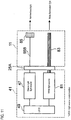
- Fig. 1 is a view illustrating an exemplary embodiment of the invention and is a conceptual block diagram of an endoscope.
- Fig. 2 is an appearance view of an example of the endoscope shown in Fig. 1 .
- an endoscope 100 includes an endoscope 11, a control apparatus 13 to which the endoscope 11 is connected, a display section 15 that is connected to the control apparatus 13 and displays image information, and an input section 17 that receives an input operation.
- the endoscope 11 is an electronic endoscope having an illumination optical system that emits illumination light from a leading end of an endoscope insertion part 19, which is inserted into an object to be examined, and an imaging optical system including an imaging device 21 (see Fig. 1 ) that has detection pixels of plural colors and captures a region to be observed.
- the endoscope 11 has the endoscope insertion part 19, an operation section 23 (see Fig. 2 ) that performs a bending operation of the leading end of the endoscope insertion part 19 and an observation operation, and connector sections 25A, 25B enabling the endoscope 11 to be detachably connected to the control apparatus 13.
- various channels such as a forceps channel for inserting a treatment tool for collecting tissue and an air supply/water supply channel are provided in the operation section 23 and the endoscope insertion part 19.
- the endoscope insertion part 19 has a flexible part 31 having flexibility, a bending part 33 and a leading end part (hereinafter, referred to as endoscope leading end part) 35.
- the endoscope leading end part 35 has irradiation ports 37A, 37B through which light is applied to a region to be observed, and an imaging device 21 that obtains image information of the region to be observed, such as CCD (Charge Coupled Device) type image sensor or CMOS (Complementary Metal-Oxide Semiconductor) type image sensor.
- an object lens unit 39 is arranged in front of a light-receiving surface of the imaging device 21 in front of a light-receiving surface of the imaging device 21, in front of a light-receiving surface of the imaging device 21, in front of a light-receiving surface of the imaging device 21, an object lens unit 39 is arranged.
- a CCD type image sensor it is possible to obtain a captured image having low noise and less image distortion because of the global shutter of
- the bending part 33 is provided between the flexible part 31 and the leading end part 35, and can be bent by a rotation operation of an angle knob 22 disposed in the operation section 23 shown in Fig. 2 .
- the bending part 33 can be bent in arbitrary direction and arbitrary angle, depending on parts of an object to be examined for which the endoscope 11 is used, thereby enabling observation directions of the irradiation ports 37A, 37B and imaging device 21 of the endoscope leading end part 35 to be directed toward a desired observation part.
- the irradiation ports 37A, 37B of the endoscope insertion part 19 are provided with a cover glass or lens.
- the control apparatus 13 has a light source device 41 that generates illumination light to be supplied to the irradiation ports 37A, 37B of the endoscope leading end part 35, and a processor 43 that executes image processing for a captured image signal from the imaging device 21.
- the control apparatus 13 is connected to the endoscope 11 via the connector sections 25A, 25B.
- the processor 43 is connected with the display section 15 and the input section 17.
- the processor 43 executes the image processing for the captured image signal transmitted from the endoscope 11, based on a command from the operation section 23 or input section 17 of the endoscope 11, and generates and supplies images to the display section 15 for display.
- the light source device 41 has a blue laser light source (white illumination light source) 45 having a center wavelength of 445 nm and a purple laser light source (special light source) 47 having a center wavelength of 405 nm, as light emitting sources.
- the light emitted from the semiconductor light emitting devices of the respective light sources 45, 47 are individually controlled by a light source control section 49, so that a light amount ratio of the light emitted from the blue laser light source 45 and the light emitted from the purple laser light source 47 can be changed.
- Examples of the blue laser light source 45 and the purple laser light source 47 include InGaN-based laser diodes of a broad area type. Alternatively, InGaNAs-based diodes or GaNAs-based diodes may be also used. Additionally, a light emitting element such as light emitting diode may be used for the light sources.
- the laser light emitted from the respective light sources 45, 47 are respectively input to optical fibers by condenser lenses (not shown) and are transmitted to the connector section 25A via a combiner 51, which is an optical multiplexer, and a coupler 53, which is an optical demultiplexer. It is noted that the invention is not limited thereto.
- the laser light from the respective light sources 45, 47 may be directly transmitted to the connector section 25A without using the combiner 51 and the coupler 53.
- the laser light which are transmitted to the connector section 25A after the blue laser light having the center wavelength of 445 nm and the purple laser light source having the center wavelength of 405 nm are combined, are transmitted to the endoscope leading end part 35 of the endoscope 11 by optical fibers 55A, 55B, respectively.
- the blue laser light excites fluorescent materials 57, which are an example of wavelength conversion members disposed at light emitting ends of the optical fibers 55A, 55B of the endoscope leading end part 35, thereby emitting fluorescence.
- a part of the blue laser light passes through the fluorescent materials 57, as it is.
- the purple laser light passes through the fluorescent materials 57 without exciting the fluorescent materials 57, so that it becomes illumination light of a narrow-band wavelength.
- the optical fibers 55A, 55B are multimode fibers.
- a thin fiber cable having a core diameter of 105 ⁇ m, a clad diameter of 125 ⁇ m and a diameter ⁇ of 0.3 to 0.5 mm, which includes a protective layer that is an outer cover, may be used, for example.
- the fluorescent materials 57 include plural fluorescent materials (for example, YAG-based fluorescent materials or fluorescent materials of BAM (BaMgAl 10 O 17 )) that absorb a part of the blue laser light to excitedly emit light of green to yellow Thereby, the light of green to yellow, which are obtained by the excitation light of the blue laser light, and the blue laser light, which passes through the fluorescent materials 57 without being absorbed by the fluorescent materials 57, are combined to constitute white (pseudo-white) illumination light.
- fluorescent materials for example, YAG-based fluorescent materials or fluorescent materials of BAM (BaMgAl 10 O 17 )
- the semiconductor light emitting devices when used as the excitation light sources, it is possible to obtain the white light of high intensity in a high light emitting efficiency, to easily adjust an intensity of the white light and to suppress changes in color temperatures and chromaticity of the white light.
- the fluorescent materials 57 can prevent noise superposition, which is an obstacle to the imaging, or flicker that is generated when displaying a moving picture, which are caused due to speckles generated by coherence of the laser lights.
- the fluorescent material 57 is preferably made of material in which light of an infrared region is little absorbed and highly scattered, taking into consideration a difference of refractive indices between a fluorescent substance constituting the fluorescent material and a resin for fixing and solidification becoming a filler. Thereby, it is possible to increase a scattering effect without decreasing the intensity of light of red or infrared region, so that an optical loss is reduced.
- Fig. 3 is a graph showing spectra of the purple laser light from the purple laser light source 47 and blue laser light from the blue laser light source 45 and emission spectrum which is obtained by wavelength-converting the blue laser light by the fluorescent materials 57.
- the purple laser light is indicated with an emission line having a center wavelength of 405 nm (profile A).
- the blue laser light is indicated with an emission line having a center wavelength of 445 nm.
- the excited emission light from the fluorescent materials 57 by the blue laser light forms a spectral intensity distribution in which luminescence intensity is increased in a wavelength band of about 450 nm to 700 nm.
- the white light is formed by the profile B of the excited emission light and blue laser light.
- the white light described in the specification is not strictly limited to the light including all wavelength components of the visible lights.
- the white light may include light of specific wavelength bands such as R (red), G (green) and B (blue) that are reference colors.
- the white light may include light including wavelength components from green to red or light including wavelength components from blue to green, in a broad sense.
- the endoscope 100 it is possible to relatively increase or decrease the luminescence intensities of the profiles A and B by the light source control section 49 and to thus generate illumination light having any brightness balance.
- the illumination light including the white light, which is formed by the blue laser light and the excited emission light from the fluorescent materials 57, and the narrow-band light by the purple laser light is applied toward a region to be observed of an object to be examined from the leading end part 35 of the endoscope 11.
- An image of the region to be observed to which the illumination light is applied is formed on the light receiving surface of the imaging device 21 by the object lens unit 39 and captured.
- a captured image signal output from the imaging device 21 after the imaging is transmitted to an A/D converter 65 through a scope cable 63, which is then converted into a digital signal.
- the converted signal is input to an image processing section 67 of the processor 43 through the connector section 25B.
- the image processing section 67 converts the input digital image signal to image data and outputs, to a control section 73, desired output image information and a control signal for the light source control section 49, in cooperation with an image analysis section 69 and a light amount control signal generation section 71, which will be specifically described below.
- the output image information which is input to the control section 73 is displayed on the display section 15 as an endoscope observation image, and is stored in a storage section 75 having a memory or a storage device, if necessary.
- the endoscope 11 includes a mode switching button 77 which will be described in detail below, and a switching signal from the mode switching button 77 is input to the control section 73.
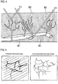
- Fig. 4 schematically shows blood vessels in mucosal surface of body tissue.
- the mucosal surface of body tissue is reported in which capillary vessels B2 such as dendritic vascular network are formed to extend from blood vessels B1 of deep mucosa to the mucosal surface, and it has been reported that the lesions of the body tissue are exhibited in the microstructure of the capillary vessels B2. Accordingly, when performing an endoscope diagnosis, it is attempted to find a micro lesion in early stage or to diagnose a range of lesions by emphasizing an image of the capillary vessels of the mucosal surface with the narrow-band light of visible short wavelengths of blue to purple.
- the illumination light When the illumination light is incident into the body tissue, the illumination light is diffusively spread in the body tissue.
- the absorption and scattering properties of the body tissue depends on wavelengths, and the scattering property is stronger as the wavelength is shorter. In other words, a degree of light reaching a deep position is changed depending on the wavelengths of the illumination light.
- the illumination light is in a wavelength band ⁇ a of about 400 nm, the blood vessel information is obtained from the capillary vessels in the mucosal surface.
- the illumination light When the illumination light is in a wavelength band ⁇ b of about 500 nm, the blood vessel information including blood vessels in the deeper layer is obtained.
- a light source having a center wavelength of 360 to 800 nm, preferably 365 to 515 nm is used.
- a light source having a center wavelength of 360 to 470 nm, preferably 360 to 450 nm is used.
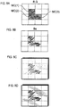
- Fig. 5 is an example of an observation image by the endoscope.
- a white light observation image which is obtained when the white light is used as the illumination light
- a blood vessel image of the relatively deep mucosa is obtained, and the brightness of the entire image can be easily enhanced.
- a narrow-band light observation image which is obtained when the narrow-band light including many visible short wavelength components is used as the illumination light, it is possible to clearly see the micro capillary vessels in the mucosal surface.
- the narrow-band light of the profile A and the white light of the profile B shown in Fig. 3 are individually emitted from the endoscope leading end part 35 and the amount of the light thereof is continuously controlled. Also, the amount of the light is controlled so that the light components of the both illumination light are included in one frame of the imaging frames by the imaging device 21. In other words, a captured image, which is obtained by imaging a region to be observed to which both the white light and the narrow-band light are applied in an arbitrary light amount ratio, becomes an observation image.
- the observation images by the both light are appropriately combined without the observation image by the narrow-band light being hidden by the observation image by the white light.
- an observation image suitable for an endoscope diagnosis which enables the micro blood vessel structure to be easily examined by emphasizing the superficial blood vessels by the narrow-band light, while brightly illuminating the entire surrounding of the observation part with the white light.
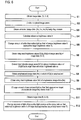
- the region to be observed is imaged by the imaging device 21.
- a resultantly obtained captured image signal is input to the image processing section 67, so that each captured image (R, G, B) having a predetermined tone expression width as shown in Fig. 7A is obtained (S1).
- the respective captured images (R, G, B) constitute image information which is obtained at the same imaging timing.
- the imaging device 21 is an imaging device of a primary color system
- detection levels of R, G and B that are detection colors are treated as brightness values of the reference colors (R, G, B).
- the imaging device is an imaging device of a complementary color system
- detection levels of three colors of C (cyan), M (magenta) and Y (yellow) which are detection colors or four colors of C, M, Y and G which are detection colors are calculated and converted into brightness values of the reference colors of R, G and B.
- the conversion of CMY or CMYG into RGB is performed by the image processing section 67, based on a predetermined calculation equation or table.
- the captured images (C, M, Y) or captured image (C, M, Y, G) which has been subjected to the A/D conversion are converted into signals of captured images (R, G, B) of the respective reference colors.
- the blue component of the shortest wavelength of the captures images (R, G, B) of the respective reference colors includes information of the superficial blood vessels B2 (see Fig. 4 ), which is obtained by the narrow-band light having the center wavelength of 405 nm.
- the image processing section 67 divides the captured images (R, G, B) of the respective reference colors into arbitrary number of image areas Mij, as shown in Fig. 7B (S2).
- the division number of the image areas may be arbitrary.
- the image analysis section 69 performs a weighting process for each image area Mij to obtain corrected image data Rc, Gc, Bc (S3).
- the weighting process is a process of emphasizing image area PA in a screen center of each captured images (R, G, B), compared to an image area PB of a screen surrounding, particularly a process of emphasizing an observation object displayed on the screen center to be carefully watched.
- the brightness value of each captured image is corrected by a matrix calculation using a correction matrix.
- the image analysis section 69 calculates a reference brightness value A that indicates brightness of the entire image of the corrected image data (Rc, Gc, Bc) (S4).
- the reference brightness value A is an index obtained by averaging the brightness values of respective pixels of the corrected image data (Rc, Gc, Bc) for all pixels (N pixels), as shown in an equation (1).
- A ⁇ N Rc + ⁇ N Gc + ⁇ N Bc 3 N
- the control section 73 changes the light amount of the white illumination light so that the reference brightness value A obtained from the corrected image data (Rc, Gc, Bc) approaches a predetermined target brightness level TL1 (S5).
- the image processing section 67 compares the reference brightness value A, which is obtained by the image analysis section 69, with the target brightness level TL, which is stored in the storage section 75 in advance, and causes the light amount control signal generation section 71 to generate a control signal to increase or decrease (change) the light amount of the light emitted from the blue laser light source 47 so that the reference brightness value A approaches the target brightness level TL.
- the generated control signal is transmitted to the light source control section 49 via the control section 73, and the light source control section 49 controls the light amount of light emitted from the blue laser light source 47, based on the input control signal.
- the image processing section 67 calculates integrated brightness values GSij, BSij of the respective pixels in the respective divided image areas Mij of the captured images (G, B) obtained in S1 (S6). In other words, the image processing section calculates the integrated brightness values GSij, BSij for each of the total of 16 image areas Mij of the captured images (G, B).
- the image processing section calculates a brightness ratio ⁇ , which is a ratio of the integrated brightness value GSij to the integrated brightness value BSij, in the image areas Mij having a same relation in image position to each other, based on an equation (2).
- the image processing section 67 extracts an image area(s) having the brightness ratio ⁇ which greater than a reference brightness ratio ⁇ c, which is a predetermined threshold value, as a characteristic image area MC(k).
- ⁇ G S i , j B S i , j
- the image processing section 67 emphasizes the respective pixels of the extracted characteristic image areas MC(k) by the weighting process, thereby obtaining blue emphasized image data (Be) as shown in Fig. 8B (S8).
- the emphasized image data (Be) is an image obtained by emphasizing the characteristic image areas MC(k) only. In the shown example, the image areas in which the capillary vessels B are displayed are emphasized so that its brightness is greater than the other image areas.
- the image processing section 67 calculates integrated brightness value BeS for the entire screen, based on an equation (3).
- BeS ⁇ N Be
- control section 73 causes the light amount control signal generation section 71 to generate a control signal to increases or decreases (change) the light amount of light emitted from the purple laser light source 47, so that the obtained integrated brightness value BeS approaches a predetermined target characteristic image brightness level TLc.
- the control signal is input to the light source control section 47 through the control section 73.
- the light source control section 49 increases the light amount of light emitted from the purple laser light source 47, and when the integrated brightness value BeS exceeds the target characteristic image brightness level TLc, the light source control section decreases the light amount of light emitted from the purple laser light source 47 (S10).
- a captured image signal is obtained by the imaging device 21, so that respective captured images (Ra, Ga, Ba) are generated (S11).
- the reference brightness value A of the captured images (Ra, Ga, Ba) is calculated by the weighting process for each image area and the equation (1).
- An example of the captured images (Ra, Ga, Ba) is shown in Fig. 8C . If the reference brightness value A exceeds the target brightness level TL, for example, if the brightness level of the captured image exceeds a maximum tone expression width as a result of the adjustment of the amount of the emitted light, it is necessary to correct.
- the reference brightness value A exceeds the target brightness level TL, the amounts of light emitted from the blue laser light source 45 and the purple laser light source 47 are decreased in a same ratio so that the reference brightness value A becomes the target brightness level TL (S 12).
- the imaging is performed by emitting the narrow-band light and the white light at the same time, so that it is possible to emphasize and display the superficial blood vessels by the narrow-band light while securing the brightness of the observation image by the white light.
- the imaging is performed by emitting the light from both the white illumination light source for normal observation and the special light source for special observation.
- the obtained observation image becomes an image in which an object (for example, superficial blood vessels and glands), which is intended to be observed by the narrow-band light, is made to have an optimal brightness level and the brightness value is not saturated for the entire image, i.e., the maximum tone expression width is not exceeded.
- the observation image it is possible to observe a detailed structure of the superficial layer emphasized by the narrow-band light in real time while seeing the entire structure of the observation part by the white illumination light.
- the cancer lesion in which a density of the micro blood vessels is increased compared to a normal part, for example, it is possible to diagnose the superficial micro blood vessels or microstructure quickly and accurately while comparing them with the surroundings of the lesion part.
- the blue laser light source 45 and the purple laser light source 47 are turned on at the same time to perform the imaging, it may be possible to alternately turn on the light sources 45 and 47 within a light receiving time period in one frame of the imaging device. In this case, it is possible to save the power and suppress the heat generation.
- the brightness level control of the captured image signal is switched between ON and OFF by pushing the mode switching button 77 (see Fig. 1 ).
- the special light observation mode is made effective, so that it is possible to perform the observation by the white light illumination and the narrow-band light at the same time.
- the normal observation mode is made effective, so that it is possible to change the light amount of light emitted from the purple laser light source 47 in the same ratio as the light amount of light emitted from the blue laser light source 45. In this manner, it is possible to improve the usability of the endoscope by selectively switching between the special light observation mode and the normal observation mode.
- the observation object by the narrow-band light may be autofluorescence or drug fluorescence from the body tissue, in addition to the superficial capillary vessels or micro mucosa shape of the body tissue.
- the intensity of the return light from the region to be observed may be appropriately changed into a state suitable for diagnosis.
- Fig. 9 shows another example of emission spectra of illumination light by the white illumination light source, the special light source and the fluorescent material.
- the fluorescent material is excited by not only the blue laser light having the wavelength of 445 nm but also the purple laser light having the wavelength of 405 nm.
- the state that the entire observation image is bluish can be mitigated by the excitation light of the fluorescent material caused by the purple laser light, so that it is possible to suppress the change in color balance of the white illumination.
- an excitation light emission amount of the fluorescent material by the purple laser light is set to be one-several-th (at least 1/3, preferably 1/5, more preferably 1/10 or less) of an excitation light emission amount by the blue laser light. In this manner, by suppressing the excited emission light of the fluorescent material by the purple laser light, it is possible to perform the special light observation while properly keeping the color temperature of the white illumination.
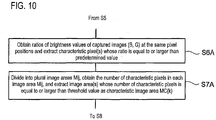
- the extraction of the characteristic image area MC(k) may be performed as follows. That is, the characteristic image area(s) MC(k) are extracted by comparing the brightness values of the captured images (B, G) in divided image area units of the captured images (B, G). However, when comparing the brightness values of the captured images (B, G) in pixel units of each captured image, it is possible to extract an object to be emphasized by the narrow-band light more accurately. More specifically, as shown in Fig. 10 illustrating alternative sequences of S6 and S7 of Fig.
- a ratio of a brightness value of the captured image (B), which includes much information of reflection light of the narrow-band light having the center wavelength of 405 nm, to a brightness value of the captured image (G) at the same pixel position is calculated, and a characteristic pixel(s) in which the ratio is equal to or greater than a predetermined ratio are extracted (S6A).
- the captured image (B) and the captured image (G) are commonly divided into the image areas Mij, and the number of extracted characteristic pixels is calculated for each of the image areas Mij. Then, an image area(s) in which the number of characteristic pixels is equal to or greater than a predetermined threshold value are extracted as the characteristic image area(s) MC(k) (S7A).
- Fig. 11 shows a schematic structure of another endoscope in which the white light source is modified.
- a white light source 81 a light source, which emits light of a broad wavelength band, such as a halogen lamp, a xenon lamp or a white light emitting diode, is used to emit the white illumination light from the leading end of the endoscope 11 through a light guide 83 that is an optical fiber bundle.
- the light emitted from the special-light light source 47 is transmitted to the leading end of the endoscope 11 through the connector section 25A by the optical fiber 55B, as described above.
- the light is provided as narrow-band light from a light deflection/diffusion member 85 that is disposed at a light emitting end of the optical fiber 55B.
- the light deflection/diffusion member 85 may be replaced with a light irradiation window that is disposed at the leading end of the endoscope 11.
- the white illumination light having high color rendering properties and having a broad spectrum characteristic with a simple structure. Furthermore, it is possible to suppress the heat generation of the leading end of the endoscope. In addition, since it is possible to completely separate and emit the white illumination light and the narrow-band light, it is possible to emit the narrow-band light to a region to be observed without a fluorescent material. Therefore, it is possible to remove the unnecessary light emission from the fluorescent material, so that it is possible to easily control the light amount.
- Fig. 12 shows a schematic structure of further another endoscope in which the structure of the special light source is modified.
- the optical system of the white illumination light is omitted, and any structure shown in Fig. 1 or Fig. 11 may be used.
- the special light source of this structure generates the narrow-band light by (i) a white light source 47A, which emits light of a broad wavelength band such as a halogen lamp, a xenon lamp or a white light emitting diode, in place of the purple laser light source 47 emitting the narrow-band light, and (ii) optical filter 111.
- the transmitted light from the optical filter 111 is introduced into a light incident end of a light guide 112 by a light collection member 113 and is guided to the leading end of the endoscope 11 by the light guide 112.
- the optical filter 111 is a narrow band-pass filter that allows only a predetermined narrow-band wavelength component of incident white light to pass therethrough and is formed in a part of a rotation filter plate 115.
- the rotation filter plate 115 can switch among the optical filters 111, which are disposed in the middle of a light path of the white light, through rotation driving by a motor M. That is, plural optical filters 111, 117, 119 (the number of optical filters is not limited to three) are disposed in the middle of the light path so as to be switched and thus, so that the narrow-band lights of different types can be emitted.
- the invention is not limited to the above exemplary embodiments.
- the exemplary embodiments can be changed and/or modified by one skilled in the art based on the specification and the well-known technology, which are within the scope of the invention to be protected.
Landscapes
- Health & Medical Sciences (AREA)
- Life Sciences & Earth Sciences (AREA)
- Surgery (AREA)
- Engineering & Computer Science (AREA)
- Biomedical Technology (AREA)
- Heart & Thoracic Surgery (AREA)
- Pathology (AREA)
- Radiology & Medical Imaging (AREA)
- Nuclear Medicine, Radiotherapy & Molecular Imaging (AREA)
- Biophysics (AREA)
- Physics & Mathematics (AREA)
- Optics & Photonics (AREA)
- Medical Informatics (AREA)
- Molecular Biology (AREA)
- Animal Behavior & Ethology (AREA)
- General Health & Medical Sciences (AREA)
- Public Health (AREA)
- Veterinary Medicine (AREA)
- Signal Processing (AREA)
- Endoscopes (AREA)
Applications Claiming Priority (3)
| Application Number | Priority Date | Filing Date | Title |
|---|---|---|---|
| JP2009219241 | 2009-09-24 | ||
| JP2010146866 | 2010-06-28 | ||
| JP2010163443A JP5460507B2 (ja) | 2009-09-24 | 2010-07-20 | 内視鏡装置の作動方法及び内視鏡装置 |
Publications (3)
| Publication Number | Publication Date |
|---|---|
| EP2301416A1 EP2301416A1 (en) | 2011-03-30 |
| EP2301416A8 EP2301416A8 (en) | 2011-09-21 |
| EP2301416B1 true EP2301416B1 (en) | 2018-01-10 |
Family
ID=43086028
Family Applications (1)
| Application Number | Title | Priority Date | Filing Date |
|---|---|---|---|
| EP10178435.3A Active EP2301416B1 (en) | 2009-09-24 | 2010-09-22 | Method of controlling endoscope and endoscope |
Country Status (3)
| Country | Link |
|---|---|
| US (1) | US8936548B2 (enExample) |
| EP (1) | EP2301416B1 (enExample) |
| JP (1) | JP5460507B2 (enExample) |
Families Citing this family (26)
| Publication number | Priority date | Publication date | Assignee | Title |
|---|---|---|---|---|
| JP5389612B2 (ja) * | 2009-11-06 | 2014-01-15 | 富士フイルム株式会社 | 電子内視鏡システム、電子内視鏡用のプロセッサ装置、及び電子内視鏡システムの作動方法 |
| JP5616303B2 (ja) * | 2010-08-24 | 2014-10-29 | 富士フイルム株式会社 | 電子内視鏡システム及び電子内視鏡システムの作動方法 |
| JP5709691B2 (ja) * | 2011-08-23 | 2015-04-30 | 富士フイルム株式会社 | 内視鏡装置 |
| JP5303015B2 (ja) | 2011-08-29 | 2013-10-02 | 富士フイルム株式会社 | 内視鏡診断装置 |
| JP5844230B2 (ja) * | 2011-10-12 | 2016-01-13 | 富士フイルム株式会社 | 内視鏡システム及びその作動方法 |
| JP2013123477A (ja) * | 2011-12-13 | 2013-06-24 | Olympus Corp | 複数の導光部材を有する照射モジュール |
| EP2797491B1 (en) | 2011-12-29 | 2018-05-30 | Cook Medical Technologies LLC | Space-optimized visualization catheter with camera train holder |
| US9668643B2 (en) | 2011-12-29 | 2017-06-06 | Cook Medical Technologies Llc | Space-optimized visualization catheter with oblong shape |
| EP2797490B1 (en) | 2011-12-29 | 2016-11-09 | Cook Medical Technologies LLC | Space-optimized visualization catheter having a camera train holder in a catheter with off-centered lumens |
| JP5815426B2 (ja) | 2012-01-25 | 2015-11-17 | 富士フイルム株式会社 | 内視鏡システム、内視鏡システムのプロセッサ装置、及び画像処理方法 |
| JP5654511B2 (ja) * | 2012-03-14 | 2015-01-14 | 富士フイルム株式会社 | 内視鏡システム、内視鏡システムのプロセッサ装置、及び内視鏡システムの作動方法 |
| JP5677378B2 (ja) | 2012-07-25 | 2015-02-25 | 富士フイルム株式会社 | 内視鏡システム |
| WO2014205738A1 (zh) * | 2013-06-27 | 2014-12-31 | 中国科学院自动化研究所 | 基于内窥镜的多光谱视频导航系统和方法 |
| JP5654167B1 (ja) * | 2013-07-03 | 2015-01-14 | 富士フイルム株式会社 | 内視鏡システム及びその作動方法 |
| CN105451634B (zh) * | 2013-07-11 | 2018-12-07 | 奥林巴斯株式会社 | 光源装置 |
| KR101480016B1 (ko) * | 2013-08-23 | 2015-01-07 | 주식회사 현주인테크 | 휴대가 가능한 내시경 시스템 |
| US9526404B2 (en) * | 2013-10-06 | 2016-12-27 | Gyrus Acmi, Inc. | Endoscope illumination system |
| JP6392570B2 (ja) * | 2014-07-11 | 2018-09-19 | オリンパス株式会社 | 画像処理装置、画像処理装置の作動方法、画像処理プログラム、及び内視鏡システム |
| CN104161493B (zh) * | 2014-07-22 | 2016-04-20 | 清华大学深圳研究生院 | 偏振成像内窥镜系统及内窥成像方法 |
| WO2016080130A1 (ja) | 2014-11-20 | 2016-05-26 | オリンパス株式会社 | 観察装置 |
| CN210055947U (zh) * | 2018-11-19 | 2020-02-14 | 苏州新光维医疗科技有限公司 | 一种内窥镜光源 |
| CN109222858A (zh) * | 2018-11-19 | 2019-01-18 | 苏州新光维医疗科技有限公司 | 具有多种光源的内窥镜结构 |
| JP7281308B2 (ja) * | 2019-03-07 | 2023-05-25 | ソニー・オリンパスメディカルソリューションズ株式会社 | 医療用画像処理装置及び医療用観察システム |
| WO2022056642A1 (en) * | 2020-09-18 | 2022-03-24 | Stryker European Operations Limited | Systems and methods for fluorescence visualization |
| WO2023287813A1 (en) * | 2021-07-13 | 2023-01-19 | Boston Scientific Scimed Inc. | Medical illumination systems and methods of using the same |
| CN115711728B (zh) * | 2022-10-19 | 2023-08-22 | 广州为实光电医疗科技有限公司 | 一种内窥镜照明有效性的测试方法及系统 |
Family Cites Families (51)
| Publication number | Priority date | Publication date | Assignee | Title |
|---|---|---|---|---|
| US5209220A (en) * | 1989-10-05 | 1993-05-11 | Olympus Optical Co., Ltd. | Endoscope image data compressing apparatus |
| US5512940A (en) * | 1993-03-19 | 1996-04-30 | Olympus Optical Co., Ltd. | Image processing apparatus, endoscope image sensing and processing apparatus, and image processing method for performing different displays depending upon subject quantity |
| US5749830A (en) * | 1993-12-03 | 1998-05-12 | Olympus Optical Co., Ltd. | Fluorescent endoscope apparatus |
| US7179222B2 (en) * | 1996-11-20 | 2007-02-20 | Olympus Corporation | Fluorescent endoscope system enabling simultaneous achievement of normal light observation based on reflected light and fluorescence observation based on light with wavelengths in infrared spectrum |
| US6293911B1 (en) * | 1996-11-20 | 2001-09-25 | Olympus Optical Co., Ltd. | Fluorescent endoscope system enabling simultaneous normal light observation and fluorescence observation in infrared spectrum |
| JP2002500907A (ja) * | 1998-01-26 | 2002-01-15 | マサチユセツツ・インスチチユート・オブ・テクノロジイ | 蛍光画像化用内視鏡 |
| EP1759631B1 (en) * | 2000-06-06 | 2011-03-09 | FUJIFILM Corporation | Fluorescent-light image display method and apparatus therefor |
| JP3559755B2 (ja) * | 2000-07-27 | 2004-09-02 | オリンパス株式会社 | 内視鏡装置 |
| EP1302152B1 (en) | 2000-07-21 | 2013-03-20 | Olympus Corporation | Endoscope apparatus |
| JP2002345733A (ja) * | 2001-05-29 | 2002-12-03 | Fuji Photo Film Co Ltd | 撮像装置 |
| JP3862582B2 (ja) * | 2001-06-29 | 2006-12-27 | 富士フイルムホールディングス株式会社 | 蛍光画像取得方法および装置並びにプログラム |
| US8620410B2 (en) * | 2002-03-12 | 2013-12-31 | Beth Israel Deaconess Medical Center | Multi-channel medical imaging system |
| AU2003218116A1 (en) * | 2002-03-12 | 2003-09-29 | Beth Israel Deaconess Medical Center | Medical imaging systems |
| US20050027166A1 (en) * | 2003-06-17 | 2005-02-03 | Shinya Matsumoto | Endoscope system for fluorescent observation |
| JP4535697B2 (ja) * | 2003-07-23 | 2010-09-01 | オリンパス株式会社 | 生体組織の光散乱観測内視鏡装置 |
| US8473035B2 (en) * | 2003-09-15 | 2013-06-25 | Beth Israel Deaconess Medical Center | Medical imaging systems |
| JP2005131129A (ja) * | 2003-10-30 | 2005-05-26 | Olympus Corp | 撮像装置及び内視鏡装置 |
| JP4554944B2 (ja) | 2004-01-15 | 2010-09-29 | Hoya株式会社 | 内視鏡装置 |
| JP3813961B2 (ja) * | 2004-02-04 | 2006-08-23 | オリンパス株式会社 | 内視鏡用信号処理装置 |
| JP4611674B2 (ja) * | 2004-06-29 | 2011-01-12 | Hoya株式会社 | 電子内視鏡システム |
| JP4575720B2 (ja) * | 2004-07-23 | 2010-11-04 | Hoya株式会社 | 電子内視鏡システム |
| KR100895160B1 (ko) * | 2004-08-30 | 2009-05-04 | 올림푸스 가부시키가이샤 | 내시경 장치 |
| JP4384626B2 (ja) * | 2004-09-02 | 2009-12-16 | オリンパス株式会社 | 内視鏡装置 |
| WO2006038502A1 (ja) * | 2004-10-01 | 2006-04-13 | Nichia Corporation | 発光装置 |
| JP4732769B2 (ja) * | 2005-03-04 | 2011-07-27 | 富士フイルム株式会社 | 内視鏡装置 |
| US7907775B2 (en) * | 2005-04-27 | 2011-03-15 | Olympus Medical Systems Corp. | Image processing apparatus, image processing method and image processing program |
| CN101163438B (zh) * | 2005-05-11 | 2011-09-14 | 奥林巴斯医疗株式会社 | 生物体观测装置和用于生物体观测装置的信号处理装置 |
| EP1880657B1 (en) * | 2005-05-12 | 2017-01-18 | Olympus Corporation | Biological observation apparatus |
| RU2378977C2 (ru) * | 2005-05-13 | 2010-01-20 | Олимпус Медикал Системз Корп. | Устройство для биологических наблюдений |
| JP4723281B2 (ja) * | 2005-05-16 | 2011-07-13 | Hoya株式会社 | 電子内視鏡システム |
| EP1728464B1 (en) | 2005-06-03 | 2016-03-30 | Olympus Corporation | Endoscope image pickup system |
| JP4716801B2 (ja) | 2005-06-16 | 2011-07-06 | オリンパスメディカルシステムズ株式会社 | 内視鏡撮像システム |
| JP4875319B2 (ja) * | 2005-06-20 | 2012-02-15 | オリンパスメディカルシステムズ株式会社 | 内視鏡 |
| JP5191090B2 (ja) * | 2005-07-15 | 2013-04-24 | オリンパスメディカルシステムズ株式会社 | 内視鏡装置 |
| JP4709606B2 (ja) * | 2005-07-28 | 2011-06-22 | オリンパスメディカルシステムズ株式会社 | 生体観測装置 |
| JP2007111357A (ja) * | 2005-10-21 | 2007-05-10 | Olympus Medical Systems Corp | 生体撮像装置及び生体観測システム |
| JP5057675B2 (ja) * | 2006-03-03 | 2012-10-24 | オリンパスメディカルシステムズ株式会社 | 生体観察装置 |
| JP5214853B2 (ja) * | 2006-03-03 | 2013-06-19 | オリンパスメディカルシステムズ株式会社 | 内視鏡装置 |
| JP4951256B2 (ja) * | 2006-03-16 | 2012-06-13 | オリンパスメディカルシステムズ株式会社 | 生体観測装置 |
| KR101050874B1 (ko) * | 2006-04-12 | 2011-07-20 | 올림푸스 메디칼 시스템즈 가부시키가이샤 | 내시경 장치 |
| EP2008573B1 (en) * | 2006-04-20 | 2017-05-31 | Olympus Corporation | Biological observation system |
| JP5355846B2 (ja) * | 2006-05-08 | 2013-11-27 | オリンパスメディカルシステムズ株式会社 | 内視鏡用画像処理装置 |
| JP4868976B2 (ja) * | 2006-08-18 | 2012-02-01 | オリンパスメディカルシステムズ株式会社 | 内視鏡装置 |
| JP5325396B2 (ja) * | 2007-06-15 | 2013-10-23 | オリンパスメディカルシステムズ株式会社 | 撮像システム |
| JP5184016B2 (ja) * | 2007-09-12 | 2013-04-17 | オンセミコンダクター・トレーディング・リミテッド | 撮像装置 |
| JP2009142415A (ja) * | 2007-12-13 | 2009-07-02 | Fujinon Corp | 内視鏡システム |
| JP2009153712A (ja) * | 2007-12-26 | 2009-07-16 | Olympus Corp | 光源装置およびそれを備えた内視鏡装置 |
| WO2009094659A1 (en) * | 2008-01-24 | 2009-07-30 | Optim, Inc. | Monolithic illumination device |
| EP2241244A1 (en) * | 2008-06-04 | 2010-10-20 | Fujifilm Corporation | Illumination device for use in endoscope |
| JP5216429B2 (ja) * | 2008-06-13 | 2013-06-19 | 富士フイルム株式会社 | 光源装置および内視鏡装置 |
| JP2011200367A (ja) * | 2010-03-25 | 2011-10-13 | Fujifilm Corp | 画像撮像方法および装置 |
-
2010
- 2010-07-20 JP JP2010163443A patent/JP5460507B2/ja active Active
- 2010-09-22 EP EP10178435.3A patent/EP2301416B1/en active Active
- 2010-09-24 US US12/890,357 patent/US8936548B2/en active Active
Non-Patent Citations (1)
| Title |
|---|
| None * |
Also Published As
| Publication number | Publication date |
|---|---|
| EP2301416A8 (en) | 2011-09-21 |
| US8936548B2 (en) | 2015-01-20 |
| US20110071353A1 (en) | 2011-03-24 |
| JP2012029703A (ja) | 2012-02-16 |
| JP5460507B2 (ja) | 2014-04-02 |
| EP2301416A1 (en) | 2011-03-30 |
Similar Documents
| Publication | Publication Date | Title |
|---|---|---|
| EP2301416B1 (en) | Method of controlling endoscope and endoscope | |
| US8834359B2 (en) | Method of controlling endoscope and endoscope | |
| US9044163B2 (en) | Endoscope apparatus | |
| EP3437542B1 (en) | Image processing device, operation method for image processing device, and image processing program | |
| US9456738B2 (en) | Endoscopic diagnosis system | |
| US9095250B2 (en) | Endoscope apparatus with particular illumination, illumination control and image processing | |
| EP2465431B1 (en) | Endoscope system and processor of endoscope system | |
| US9918613B2 (en) | Endoscope system and operating method thereof | |
| EP2689713B1 (en) | Endoscope system | |
| EP2371267A1 (en) | Endoscope apparatus | |
| EP2452610A1 (en) | Lighting device for endoscope, and endoscope device | |
| US20130289373A1 (en) | Endoscopic diagnosis system | |
| CN106132275B (zh) | 观察图像取得系统以及观察图像取得方法 | |
| US9414739B2 (en) | Imaging apparatus for controlling fluorescence imaging in divided imaging surface | |
| US20140340497A1 (en) | Processor device, endoscope system, and operation method of endoscope system | |
| JP6550420B2 (ja) | 内視鏡装置 | |
| US20190246874A1 (en) | Processor device, endoscope system, and method of operating processor device | |
| JP2012050641A (ja) | 内視鏡システム | |
| JP5538143B2 (ja) | 内視鏡システム | |
| JP5677555B2 (ja) | 内視鏡装置 | |
| JP2015171442A (ja) | 内視鏡用光源装置及び内視鏡システム | |
| JP6669539B2 (ja) | 画像処理装置、画像処理装置の作動方法、および画像処理プログラム | |
| JP5965028B2 (ja) | 内視鏡システム |
Legal Events
| Date | Code | Title | Description |
|---|---|---|---|
| PUAI | Public reference made under article 153(3) epc to a published international application that has entered the european phase |
Free format text: ORIGINAL CODE: 0009012 |
|
| AK | Designated contracting states |
Kind code of ref document: A1 Designated state(s): AL AT BE BG CH CY CZ DE DK EE ES FI FR GB GR HR HU IE IS IT LI LT LU LV MC MK MT NL NO PL PT RO SE SI SK SM TR |
|
| AX | Request for extension of the european patent |
Extension state: BA ME RS |
|
| RIN1 | Information on inventor provided before grant (corrected) |
Inventor name: ENDO, AZUCHI Inventor name: ERIKAWA, AKIHIKO Inventor name: OZAWA, SATOSHI |
|
| 17P | Request for examination filed |
Effective date: 20110929 |
|
| GRAP | Despatch of communication of intention to grant a patent |
Free format text: ORIGINAL CODE: EPIDOSNIGR1 |
|
| RIC1 | Information provided on ipc code assigned before grant |
Ipc: A61B 1/04 20060101AFI20170629BHEP Ipc: A61B 1/05 20060101ALN20170629BHEP |
|
| RIC1 | Information provided on ipc code assigned before grant |
Ipc: A61B 1/04 20060101AFI20170707BHEP Ipc: A61B 1/05 20060101ALN20170707BHEP |
|
| INTG | Intention to grant announced |
Effective date: 20170727 |
|
| GRAS | Grant fee paid |
Free format text: ORIGINAL CODE: EPIDOSNIGR3 |
|
| GRAA | (expected) grant |
Free format text: ORIGINAL CODE: 0009210 |
|
| AK | Designated contracting states |
Kind code of ref document: B1 Designated state(s): AL AT BE BG CH CY CZ DE DK EE ES FI FR GB GR HR HU IE IS IT LI LT LU LV MC MK MT NL NO PL PT RO SE SI SK SM TR |
|
| REG | Reference to a national code |
Ref country code: GB Ref legal event code: FG4D |
|
| REG | Reference to a national code |
Ref country code: CH Ref legal event code: EP Ref country code: AT Ref legal event code: REF Ref document number: 961490 Country of ref document: AT Kind code of ref document: T Effective date: 20180115 |
|
| REG | Reference to a national code |
Ref country code: IE Ref legal event code: FG4D |
|
| REG | Reference to a national code |
Ref country code: DE Ref legal event code: R096 Ref document number: 602010047896 Country of ref document: DE |
|
| REG | Reference to a national code |
Ref country code: NL Ref legal event code: MP Effective date: 20180110 |
|
| REG | Reference to a national code |
Ref country code: AT Ref legal event code: MK05 Ref document number: 961490 Country of ref document: AT Kind code of ref document: T Effective date: 20180110 |
|
| PG25 | Lapsed in a contracting state [announced via postgrant information from national office to epo] |
Ref country code: NL Free format text: LAPSE BECAUSE OF FAILURE TO SUBMIT A TRANSLATION OF THE DESCRIPTION OR TO PAY THE FEE WITHIN THE PRESCRIBED TIME-LIMIT Effective date: 20180110 |
|
| PG25 | Lapsed in a contracting state [announced via postgrant information from national office to epo] |
Ref country code: NO Free format text: LAPSE BECAUSE OF FAILURE TO SUBMIT A TRANSLATION OF THE DESCRIPTION OR TO PAY THE FEE WITHIN THE PRESCRIBED TIME-LIMIT Effective date: 20180410 Ref country code: FI Free format text: LAPSE BECAUSE OF FAILURE TO SUBMIT A TRANSLATION OF THE DESCRIPTION OR TO PAY THE FEE WITHIN THE PRESCRIBED TIME-LIMIT Effective date: 20180110 Ref country code: LT Free format text: LAPSE BECAUSE OF FAILURE TO SUBMIT A TRANSLATION OF THE DESCRIPTION OR TO PAY THE FEE WITHIN THE PRESCRIBED TIME-LIMIT Effective date: 20180110 Ref country code: HR Free format text: LAPSE BECAUSE OF FAILURE TO SUBMIT A TRANSLATION OF THE DESCRIPTION OR TO PAY THE FEE WITHIN THE PRESCRIBED TIME-LIMIT Effective date: 20180110 Ref country code: ES Free format text: LAPSE BECAUSE OF FAILURE TO SUBMIT A TRANSLATION OF THE DESCRIPTION OR TO PAY THE FEE WITHIN THE PRESCRIBED TIME-LIMIT Effective date: 20180110 Ref country code: CY Free format text: LAPSE BECAUSE OF FAILURE TO SUBMIT A TRANSLATION OF THE DESCRIPTION OR TO PAY THE FEE WITHIN THE PRESCRIBED TIME-LIMIT Effective date: 20180110 |
|
| REG | Reference to a national code |
Ref country code: FR Ref legal event code: PLFP Year of fee payment: 9 |
|
| PG25 | Lapsed in a contracting state [announced via postgrant information from national office to epo] |
Ref country code: SE Free format text: LAPSE BECAUSE OF FAILURE TO SUBMIT A TRANSLATION OF THE DESCRIPTION OR TO PAY THE FEE WITHIN THE PRESCRIBED TIME-LIMIT Effective date: 20180110 Ref country code: IS Free format text: LAPSE BECAUSE OF FAILURE TO SUBMIT A TRANSLATION OF THE DESCRIPTION OR TO PAY THE FEE WITHIN THE PRESCRIBED TIME-LIMIT Effective date: 20180510 Ref country code: LV Free format text: LAPSE BECAUSE OF FAILURE TO SUBMIT A TRANSLATION OF THE DESCRIPTION OR TO PAY THE FEE WITHIN THE PRESCRIBED TIME-LIMIT Effective date: 20180110 Ref country code: GR Free format text: LAPSE BECAUSE OF FAILURE TO SUBMIT A TRANSLATION OF THE DESCRIPTION OR TO PAY THE FEE WITHIN THE PRESCRIBED TIME-LIMIT Effective date: 20180411 Ref country code: PL Free format text: LAPSE BECAUSE OF FAILURE TO SUBMIT A TRANSLATION OF THE DESCRIPTION OR TO PAY THE FEE WITHIN THE PRESCRIBED TIME-LIMIT Effective date: 20180110 Ref country code: BG Free format text: LAPSE BECAUSE OF FAILURE TO SUBMIT A TRANSLATION OF THE DESCRIPTION OR TO PAY THE FEE WITHIN THE PRESCRIBED TIME-LIMIT Effective date: 20180410 Ref country code: AT Free format text: LAPSE BECAUSE OF FAILURE TO SUBMIT A TRANSLATION OF THE DESCRIPTION OR TO PAY THE FEE WITHIN THE PRESCRIBED TIME-LIMIT Effective date: 20180110 |
|
| REG | Reference to a national code |
Ref country code: DE Ref legal event code: R097 Ref document number: 602010047896 Country of ref document: DE |
|
| PG25 | Lapsed in a contracting state [announced via postgrant information from national office to epo] |
Ref country code: EE Free format text: LAPSE BECAUSE OF FAILURE TO SUBMIT A TRANSLATION OF THE DESCRIPTION OR TO PAY THE FEE WITHIN THE PRESCRIBED TIME-LIMIT Effective date: 20180110 Ref country code: AL Free format text: LAPSE BECAUSE OF FAILURE TO SUBMIT A TRANSLATION OF THE DESCRIPTION OR TO PAY THE FEE WITHIN THE PRESCRIBED TIME-LIMIT Effective date: 20180110 Ref country code: RO Free format text: LAPSE BECAUSE OF FAILURE TO SUBMIT A TRANSLATION OF THE DESCRIPTION OR TO PAY THE FEE WITHIN THE PRESCRIBED TIME-LIMIT Effective date: 20180110 Ref country code: IT Free format text: LAPSE BECAUSE OF FAILURE TO SUBMIT A TRANSLATION OF THE DESCRIPTION OR TO PAY THE FEE WITHIN THE PRESCRIBED TIME-LIMIT Effective date: 20180110 |
|
| PLBE | No opposition filed within time limit |
Free format text: ORIGINAL CODE: 0009261 |
|
| STAA | Information on the status of an ep patent application or granted ep patent |
Free format text: STATUS: NO OPPOSITION FILED WITHIN TIME LIMIT |
|
| PG25 | Lapsed in a contracting state [announced via postgrant information from national office to epo] |
Ref country code: CZ Free format text: LAPSE BECAUSE OF FAILURE TO SUBMIT A TRANSLATION OF THE DESCRIPTION OR TO PAY THE FEE WITHIN THE PRESCRIBED TIME-LIMIT Effective date: 20180110 Ref country code: DK Free format text: LAPSE BECAUSE OF FAILURE TO SUBMIT A TRANSLATION OF THE DESCRIPTION OR TO PAY THE FEE WITHIN THE PRESCRIBED TIME-LIMIT Effective date: 20180110 Ref country code: SM Free format text: LAPSE BECAUSE OF FAILURE TO SUBMIT A TRANSLATION OF THE DESCRIPTION OR TO PAY THE FEE WITHIN THE PRESCRIBED TIME-LIMIT Effective date: 20180110 Ref country code: SK Free format text: LAPSE BECAUSE OF FAILURE TO SUBMIT A TRANSLATION OF THE DESCRIPTION OR TO PAY THE FEE WITHIN THE PRESCRIBED TIME-LIMIT Effective date: 20180110 |
|
| 26N | No opposition filed |
Effective date: 20181011 |
|
| PG25 | Lapsed in a contracting state [announced via postgrant information from national office to epo] |
Ref country code: SI Free format text: LAPSE BECAUSE OF FAILURE TO SUBMIT A TRANSLATION OF THE DESCRIPTION OR TO PAY THE FEE WITHIN THE PRESCRIBED TIME-LIMIT Effective date: 20180110 |
|
| PG25 | Lapsed in a contracting state [announced via postgrant information from national office to epo] |
Ref country code: MC Free format text: LAPSE BECAUSE OF FAILURE TO SUBMIT A TRANSLATION OF THE DESCRIPTION OR TO PAY THE FEE WITHIN THE PRESCRIBED TIME-LIMIT Effective date: 20180110 |
|
| REG | Reference to a national code |
Ref country code: CH Ref legal event code: PL |
|
| REG | Reference to a national code |
Ref country code: BE Ref legal event code: MM Effective date: 20180930 |
|
| REG | Reference to a national code |
Ref country code: IE Ref legal event code: MM4A |
|
| PG25 | Lapsed in a contracting state [announced via postgrant information from national office to epo] |
Ref country code: LU Free format text: LAPSE BECAUSE OF NON-PAYMENT OF DUE FEES Effective date: 20180922 |
|
| PG25 | Lapsed in a contracting state [announced via postgrant information from national office to epo] |
Ref country code: IE Free format text: LAPSE BECAUSE OF NON-PAYMENT OF DUE FEES Effective date: 20180922 |
|
| PG25 | Lapsed in a contracting state [announced via postgrant information from national office to epo] |
Ref country code: BE Free format text: LAPSE BECAUSE OF NON-PAYMENT OF DUE FEES Effective date: 20180930 Ref country code: CH Free format text: LAPSE BECAUSE OF NON-PAYMENT OF DUE FEES Effective date: 20180930 Ref country code: LI Free format text: LAPSE BECAUSE OF NON-PAYMENT OF DUE FEES Effective date: 20180930 |
|
| PG25 | Lapsed in a contracting state [announced via postgrant information from national office to epo] |
Ref country code: MT Free format text: LAPSE BECAUSE OF NON-PAYMENT OF DUE FEES Effective date: 20180922 |
|
| PG25 | Lapsed in a contracting state [announced via postgrant information from national office to epo] |
Ref country code: TR Free format text: LAPSE BECAUSE OF FAILURE TO SUBMIT A TRANSLATION OF THE DESCRIPTION OR TO PAY THE FEE WITHIN THE PRESCRIBED TIME-LIMIT Effective date: 20180110 |
|
| PG25 | Lapsed in a contracting state [announced via postgrant information from national office to epo] |
Ref country code: HU Free format text: LAPSE BECAUSE OF FAILURE TO SUBMIT A TRANSLATION OF THE DESCRIPTION OR TO PAY THE FEE WITHIN THE PRESCRIBED TIME-LIMIT; INVALID AB INITIO Effective date: 20100922 Ref country code: PT Free format text: LAPSE BECAUSE OF FAILURE TO SUBMIT A TRANSLATION OF THE DESCRIPTION OR TO PAY THE FEE WITHIN THE PRESCRIBED TIME-LIMIT Effective date: 20180110 |
|
| PG25 | Lapsed in a contracting state [announced via postgrant information from national office to epo] |
Ref country code: MK Free format text: LAPSE BECAUSE OF NON-PAYMENT OF DUE FEES Effective date: 20180110 |
|
| PGFP | Annual fee paid to national office [announced via postgrant information from national office to epo] |
Ref country code: GB Payment date: 20200909 Year of fee payment: 11 Ref country code: FR Payment date: 20200812 Year of fee payment: 11 |
|
| GBPC | Gb: european patent ceased through non-payment of renewal fee |
Effective date: 20210922 |
|
| PG25 | Lapsed in a contracting state [announced via postgrant information from national office to epo] |
Ref country code: GB Free format text: LAPSE BECAUSE OF NON-PAYMENT OF DUE FEES Effective date: 20210922 Ref country code: FR Free format text: LAPSE BECAUSE OF NON-PAYMENT OF DUE FEES Effective date: 20210930 |
|
| P01 | Opt-out of the competence of the unified patent court (upc) registered |
Effective date: 20230515 |
|
| PGFP | Annual fee paid to national office [announced via postgrant information from national office to epo] |
Ref country code: DE Payment date: 20240730 Year of fee payment: 15 |