EP2300352B1 - Verschliessmaschine - Google Patents
Verschliessmaschine Download PDFInfo
- Publication number
- EP2300352B1 EP2300352B1 EP09757206.9A EP09757206A EP2300352B1 EP 2300352 B1 EP2300352 B1 EP 2300352B1 EP 09757206 A EP09757206 A EP 09757206A EP 2300352 B1 EP2300352 B1 EP 2300352B1
- Authority
- EP
- European Patent Office
- Prior art keywords
- closing
- sterile chamber
- machine according
- tool
- closures
- Prior art date
- Legal status (The legal status is an assumption and is not a legal conclusion. Google has not performed a legal analysis and makes no representation as to the accuracy of the status listed.)
- Active
Links
Images

Classifications
-
- B—PERFORMING OPERATIONS; TRANSPORTING
- B67—OPENING, CLOSING OR CLEANING BOTTLES, JARS OR SIMILAR CONTAINERS; LIQUID HANDLING
- B67C—CLEANING, FILLING WITH LIQUIDS OR SEMILIQUIDS, OR EMPTYING, OF BOTTLES, JARS, CANS, CASKS, BARRELS, OR SIMILAR CONTAINERS, NOT OTHERWISE PROVIDED FOR; FUNNELS
- B67C7/00—Concurrent cleaning, filling, and closing of bottles; Processes or devices for at least two of these operations
- B67C7/0073—Sterilising, aseptic filling and closing
- B67C7/0086—Sterilisation being restricted to the area of application of the closure
-
- B—PERFORMING OPERATIONS; TRANSPORTING
- B67—OPENING, CLOSING OR CLEANING BOTTLES, JARS OR SIMILAR CONTAINERS; LIQUID HANDLING
- B67B—APPLYING CLOSURE MEMBERS TO BOTTLES JARS, OR SIMILAR CONTAINERS; OPENING CLOSED CONTAINERS
- B67B3/00—Closing bottles, jars or similar containers by applying caps
- B67B3/02—Closing bottles, jars or similar containers by applying caps by applying flanged caps, e.g. crown caps, and securing by deformation of flanges
-
- B—PERFORMING OPERATIONS; TRANSPORTING
- B67—OPENING, CLOSING OR CLEANING BOTTLES, JARS OR SIMILAR CONTAINERS; LIQUID HANDLING
- B67B—APPLYING CLOSURE MEMBERS TO BOTTLES JARS, OR SIMILAR CONTAINERS; OPENING CLOSED CONTAINERS
- B67B3/00—Closing bottles, jars or similar containers by applying caps
- B67B3/20—Closing bottles, jars or similar containers by applying caps by applying and rotating preformed threaded caps
- B67B3/2013—Closing bottles, jars or similar containers by applying caps by applying and rotating preformed threaded caps by carousel-type capping machines
- B67B3/2033—Closing bottles, jars or similar containers by applying caps by applying and rotating preformed threaded caps by carousel-type capping machines comprising carousel co-rotating capping heads
-
- B—PERFORMING OPERATIONS; TRANSPORTING
- B67—OPENING, CLOSING OR CLEANING BOTTLES, JARS OR SIMILAR CONTAINERS; LIQUID HANDLING
- B67B—APPLYING CLOSURE MEMBERS TO BOTTLES JARS, OR SIMILAR CONTAINERS; OPENING CLOSED CONTAINERS
- B67B2201/00—Indexing codes relating to constructional features of closing machines
- B67B2201/08—Aseptic features
-
- B—PERFORMING OPERATIONS; TRANSPORTING
- B67—OPENING, CLOSING OR CLEANING BOTTLES, JARS OR SIMILAR CONTAINERS; LIQUID HANDLING
- B67C—CLEANING, FILLING WITH LIQUIDS OR SEMILIQUIDS, OR EMPTYING, OF BOTTLES, JARS, CANS, CASKS, BARRELS, OR SIMILAR CONTAINERS, NOT OTHERWISE PROVIDED FOR; FUNNELS
- B67C3/00—Bottling liquids or semiliquids; Filling jars or cans with liquids or semiliquids using bottling or like apparatus; Filling casks or barrels with liquids or semiliquids
- B67C3/02—Bottling liquids or semiliquids; Filling jars or cans with liquids or semiliquids using bottling or like apparatus
- B67C3/22—Details
- B67C2003/228—Aseptic features
Definitions
- the invention relates to a closing machine according to the preamble of claim 1 and as from GB 2 174 682 A known.
- GB 2 174 682 A is a Kranorkenversch multiplier known, in which provided around the container head a channel-like annulus, in which the closure ram retracts and which is acted upon gas inlets and outlets with an inert or sterile gas.
- a screw capper with a comparable annulus is out US 6,024,418 known, which proposes to provide the filling members and closing elements in the same annular channel.
- the object of the invention is to provide a capping machine, which is particularly suitable for use in a system for sterile and especially for cold aseptic filling of products in bottles or similar containers and for sterile sealing of these containers and thereby avoids the disadvantages mentioned above, that is, with a reduced risk of contamination, a significant reduction in cleaning and / or sterilization and / or disinfecting the sterile space required means or chemicals.
- a capping machine according to claim 1 is formed.
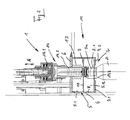
- FIGS. 1 and 2 each show in simplified representation and in partial section a sealing machine of circumferential design in the field of a sterile room, explained in more detail.
- FIG. 1 generally designated 1 sealing machine according to the invention serves in its embodiment shown in this figure for closing bottles 2, for example plastic bottles with these bottles or on the bottle mouth 2.1 by welding or sealing, ie heat attachable closures 3, for example in the form of films.
- the closing machine 1 consists of a rotor 4, which is rotatable about a vertical machine axis MA and on the circumference of which an annular axis-like sterile space 5 surrounding the machine axis MA is provided, which is bounded by several wall sections towards the surroundings, in the illustrated embodiment an upper wall section 6, a lower wall section 7, through a radially inner annular wall section 8 and outer wall sections 9.
- an intermediate wall 10 provided between the wall sections 6 and 7, the space 5 is divided into an upper subspace 5.1 and a lower subspace 5.2 .
- the outer wall sections 9 as well as the section 7.2 of the wall section 7 are not circumferentially fixed to the rotor 4 on a machine frame of the closing machine 1.
- a plurality of pouring stations 11 are further formed on the circumference of the rotor 4, of which in the FIG. 1 only one is shown and are provided distributed at equal angular intervals about the axis MA.
- Each closing station 11 consists of a closing tool in the form of an induction welding head 12, of which in the FIG. 1 only the inductively heated induction punch 12.1 extending into the space 5 or into the two subspaces 5.1 and 5.2 is shown.
- the passage of the induction punch 12 is sealed by the wall section 6.
- the induction punch 12 which extends through an opening 10.1 in the intermediate wall 10 with its lower end in the subspace 5.2, is made with the smoothest possible outer surface of a suitable, heat-conductive but corrosion-resistant material, for example made of stainless steel, for example as a passive, Heat conducting component. All other functional elements of the induction welding head 12, such as the lifting and lowering elements, for heating the induction punch 12.1, etc., are located above the wall section 6 outside the sterile room 5.
- each closing station 11 is provided with a container carrier, which is formed by an opening in the section 7.1 and on which the respective bottle 2 is suspended at a below the bottle mouth 2.1 formed mouth flange 2.2 hanging so that they only with their mouth area above the mouth flange 2.2 in the space 5 and in particular extends into the subspace 5.2.
- the space 5 is charged or flushed with a suitable gas and / or vaporous medium ensuring the sterility of this space, for example with sterile air.
- This medium is eg the lower subspace 5.2 and leaves the sterile room 5 at least partially to the upper subspace 5.1.
- the bottles 2 are each transferred to a closing position individually to the closing stations 11, so that they are held there in the manner described hanging on its mouth 2.2 with the bottle mouth 2.1 in the subspace 5.2 are arranged for closing with the closures 3.
- the sealed bottles are removed from the closing stations 11 each at a container outlet.
- the particular advantage of the closing machine 1 according to the invention or the closing stations 11 is that in the sterile room 5 only the induction stamps 12.1, which are smooth on their surfaces and have no recesses, undercuts or the like, are arranged, so that the entire room 5 can be kept germ-free with a significantly reduced effort, and in particular by increasing the time interval between cleaning and / or sterilization cycles, with shorter cycle time and reduced use of cleaning and / or sterilizing agents.
- FIG. 2 shows a capping machine 1 for closing the bottle 2 with cap-like screw caps 13, which is not part of the invention.
- the individual closing stations 11 are each equipped with a screw capper 14, which has the construction known in the art and include a drive 14.1, from a spindle or shaft receiving elongated and closed capper head 14.2 and one provided at the lower end of the capping head 14.2 and with the spindle connected Verschurgikonus or closing element 14.3.
- a drive 14.1 from a spindle or shaft receiving elongated and closed capper head 14.2 and one provided at the lower end of the capping head 14.2 and with the spindle connected Verscheriekonus or closing element 14.3.
- each screw capper 14 only with a partial length of its smooth on the outer surface and circular cylindrical capper head 14.2 through the wall section 6 in the sterile room 5 and also through the partition wall 10 into the lower portion 5.2 into it, so that with the rotary or screw caps 3a cooperating closing element 14.3 is arranged in this sub-area 5.2.
- FIG. 2 illustrated embodiment has the advantage that within the sterile room 5 and in particular also within the subspace 5.2 only those functional elements of the screw 14 are arranged, which have at least a largely smooth and easy to clean and sterilized outer surface, while others, difficult to clean and to be sterilized functional elements, such as the drive 14.1 as well as the functional elements for raising and lowering the sterversch devisers 14 are provided completely outside the room 5.
- the capping machine 1 is for example part of a system for sterile, for example cold aseptic filling of a liquid filling material in the bottles 2 or other containers and for closing the bottles 2 with the closures 3 and 3a, the bottles 2 before filling, during filling and closing as well as on the entire transport route between the filling machine and the capping constantly be moved at least with their mouth opening 2.1 having the mouth area in a sterile room.
- the closing machine 1 is not only suitable for closing the bottles 2, but also for closing other containers.
- closing tools for fastening cap-like closures to bottles by placing them on and by mechanically deforming the closures when using such closing tools only functional elements in the interior of the room 5 and the subspaces are arranged 5.1 and 5.2, which interact directly with the closures, while other functional elements, such as difficult to clean and / or sterilized functional elements such as drives and / or lifting devices for Lifting and lowering of the respective closing tool, etc. are provided outside the room 5.
- an induction welding head 12 for welding or sealing the closures 3 to the opening edge 2.1 of the bottles 2 it is also possible to use a closing tool with which the fixing or welding of the respective closure 3 to the bottles 2 takes place in a different manner, for example by ultrasonic energy and / or with appropriate formation of the closures 3 by microwave energy.
- the design of the capping machine is however of particular advantage when using such closing tools in which the part of the closing tool extending into the space 5 is a purely passive component which, as a molded part, has a corrosion-resistant, smooth surface which is free of undercuts, indentations, joints, Recesses, etc., can be easily cleaned and sterilized.
- a passive component in this sense is the induction punch 12.1, as well as, for example, in a working with ultrasound closing tool a ultrasonic energy on the closure 3 and the bottle opening or mouth 2.1 transmitting punch-like tool.
Landscapes
- Engineering & Computer Science (AREA)
- Mechanical Engineering (AREA)
- Filling Of Jars Or Cans And Processes For Cleaning And Sealing Jars (AREA)
- Sealing Of Jars (AREA)
Description
- Die Erfindung bezieht sich auf eine Verschließmaschine gemäß Oberbegriff Patentanspruch 1 und wie aus der
GB 2 174 682 A - Anlagen zum sterilen, insbesondere auch zum kaltaseptischen Füllen von Flaschen oder dergleichen Behältern mit einem flüssigen Füllgut, beispielsweise mit einem leicht verderblichen Füllgut, wie z.B. Milchprodukte, sowie zum anschließenden ebenfalls sterilen oder kaltaseptisch Verschließen der Behälter sind bekannt. Die Flaschen oder Behälter werden hierbei bereits bei der Aufgabe an die Füllmaschine, während des Füllens, bei der Weiterleitung von der Füllmaschine an eine nachfolgende Verschließmaschine und während des Verschließens in einem sterilen Raum bewegt, der bei laufender Anlage, d.h. beim Füllen und Verschließen mit einem sterilen gas- und/oder dampfförmigen Medium beaufschlagt und/oder durchströmt wird und der von Zeit zu Zeit, d.h. innerhalb vorgegebener Relinigungs- und Desinfektionszyklen oder -intervallen mit einem Reinlgungs- und/oder Desinfektions- und/oder Sterilisstionsmedium behandelt wird.
- Nachteilig bei bekannten Anlagen ist, dass insbesondere auch bei der jeweiligen Verschließmaschine das gesamte Equipment dieser Maschine und dabei speziell die an den Verschließpositionen vorgesehenen Verschließwerkzeuge insgesamt in dem sterilen Raum angeordnet sind, was eine teure Ausbildung dieser Verschließwerkzeuge zumindest an ihren außen liegenden Flächen und/oder Bereichen u.a. aus einem auch gegenüber den Reinigungs- und Desinfektionsmitteln korrosionsbestandigen Material, beispielsweise aus Edelstahl erforderlich macht. Weiterhin weisen die Verschließwerkzeuge an ihrer Außenfläche funktionsbedingt Ausnehmungen, Schlitze, Einkerbungen usw. auf, In denen sich bevorzugt Keime ansiedeln können, so dass bisher auch hierdurch bedingt eine vom Zeitaufwand sowie von der Menge des erforderlichen Reinigungs- und Desinfektionsmittels aufwendige Reinigung und/oder Desinfektion des sterilen Raumes im Bereich der Verschließmaschine notwendig ist.
- Aus
GB 2 174 682 A US 6,082418 bekannt, welche vorschlägt die Füllorgane und Verschließelemente in demselben Ringkanal vorzusehen. - Aufgabe der Erfindung ist es, eine Verschließmaschine aufzuzeigen, die insbesondere für die Verwendung in einer Anlage zum sterilen und dabei speziell auch zum kaltaseptischen Abfüllen von Produkten in Flaschen oder dergleichen Behältern sowie zum sterilen Verschließen dieser Behälter geeignet ist und dabei die vorstehend genannten Nachteile vermeidet, d.h. bei reduziertem Kontaminationsrisiko eine erhebliche Reduzierung der für die Reinigung und/oder Sterilisation und/oder Desinfektion des sterilen Raumes benötigten Mittel oder Chemikalien ermöglicht.
- Zur Lösung dieser Aufgabe ist eine Verschließmaschine entsprechend dem Patentanspruch 1 ausgebildet.
- Weiterbildungen, Vorteile und Anwendungsmöglichkeiten der Erfindung ergeben sich auch aus der nachfolgenden Beschreibung von Ausführungsbeispielen und aus den Figuren. Dabei sind alle beschriebenen und/oder bildlich dargestellten Merkmale für sich oder in beliebiger Kombination grundsätzlich Gegenstand der Erfindung, unabhängig von ihrer Zusammenfassung in den Ansprüchen oder deren Rückbeziehung. Auch wird der Inhalt der Ansprüche zu einem Bestandteil der Beschreibung gemacht.
- Die Erfindung wird im Folgenden anhand der
Figuren 1 und2 , die jeweils in vereinfachter Darstellung und im Teilschnitt eine Verschließmaschine umlaufender Bauart im Bereich eines sterilen Raumes zeigen, näher erläutert. - Die in der
Figur 1 allgemein mit 1 bezeichnete erfindungsgemäße Verschließmaschine dient in ihrer in dieser Figur dargestellten Ausführung zum Verschließen von Flaschen 2, beispielsweise von Kunststoffflaschen mit auf diese Flaschen bzw. auf deren Flaschenmündung 2.1 durch Aufschweißen oder Aufsiegeln, d.h. Hitzeeinwirkung befestigbaren Verschlüssen 3 beispielsweise in Form von Folien. - Die Verschließmaschine 1 besteht hierzu aus einem um eine vertikale Maschinenachse MA umlaufend antreibbaren Rotor 4, an dessen Umfang ein die Maschinenachse MA konzentrisch umschließender ringkanalartiger steriler Raum 5 vorgesehen ist, der durch mehrere Wandabschnitte zur Umgebung hin begrenzt ist, und zwar bei der dargestellten Ausführungsform durch einen oberen Wandabschnitt 6, einen unteren Wandabschnitt 7, durch einen radial innen liegenden ringförmigen Wandabschnitt 8 und äußere Wandabschnitte 9. Durch eine zwischen den Wandabschnitten 6 und 7 vorgesehene Zwischenwand 10 ist der Raum 5 in einem oberen Teilraum 5.1 und in einen unteren Teilraum 5.2 unterteilt. Bei der dargestellten Ausführungsform sind der obere Wandabschnitt 6, der innen liegende ringförmige Wandabschnitt 8, die Zwischenwand 10 sowie der Teilabschnitt 7.1 des unteren Wandabschnitts 7 am Rotor 4 und damit mit diesem umlaufend vorgesehen. Die äußeren Wandabschnitte 9 sowie auch der Teilabschnitt 7.2 des Wandabschnitts 7 sind mit dem Rotor 4 nicht umlaufend an einem Maschinengestell der Verschließmaschine 1 befestigt.
- Zum Verschließen der Flaschen 2 mit den Verschlüssen 3 sind am Umfang des Rotors 4 weiterhin mehrere Verschießstationen 11 gebildet, von denen in der
Figur 1 nur eine dargestellt ist und die in gleichmäßigen Winkelabständen um die Achse MA verteilt vorgesehen sind. Jede Verschließstation 11 besteht aus einem Verschließwerkzeug in Form eines Induktionsschweißkopfes 12, von dem in derFigur 1 lediglich der in den Raum 5 bzw. in die beiden Teilräume 5.1 und 5.2 hineinreichende induktiv beheizte Induktionsstempel 12.1 dargestellt ist. Dieser ist durch eine Öffnung 6.1 in dem oberen Wandabschnitt 6 hindurchgeführt und entsprechend dem Doppelpfeil A in seiner Stempelachse bzw. in einer vertikalen Achse parallel zur Maschinenachse MA zwischen einer oberen Ausgangsposition und einer abgesenkten Arbeitsposition bewegbar, in der der Induktionsstempel 12.1 mit seiner unteren Stempelfläche über den jeweiligen Verschluss 3 angepresst gegen die Mündungsöffnung 2.1 der an der Verschließstation 11 vorgesehenen, verschließenden Flaschen 2 anliegt und dadurch den Verschluss 3 durch Versiegeln oder Verschweißen mit der betreffenden Flasche 2 verbindet. - Mit einer aus einem geeigneten Material, beispielsweise aus Teflon bestehenden balgartigen Dichtung 13 ist der Durchtritt des Induktionsstempels 12 durch den Wandabschnitt 6 abgedichtet. Der Induktionsstempel 12, der durch eine Öffnung 10.1 in der Zwischenwand 10 mit seinem unteren Ende in den Teilraum 5.2 hineinreicht, ist mit möglichst glatter Außenfläche aus einem geeigneten, Wärme gut leitenden aber korrosionsbeständigen Material, beispielsweise aus Edelstahl hergestellt, und zwar beispielsweise als passives, Wärme leitendes Bauteil. Alle übrigen Funktionselemente des Induktionsschweißkopfes 12, wie beispielsweise die Elemente zum Anheben und Absenken, zum Beheizen des Induktionsstempels 12.1 usw. befinden sich oberhalb des Wandabschnitts 6 außerhalb des sterilen Raumes 5.
- Unterhalb des Induktionsstempels 12 ist jede Verschließstation 11 mit einem Behälterträger versehen, der von einer Öffnung in dem Teilabschnitt 7.1 gebildet ist und an dem die jeweilige Flasche 2 an einem unterhalb der Flaschenmündung 2.1 ausgebildeten Mündungsflansch 2.2 hängend derart gehalten ist, dass sie lediglich mit ihrem Mündungsbereich oberhalb des Mündungsflansches 2.2 in den Raum 5 und dabei speziell in den Teilraum 5.2 hineinreicht.
- Während des Betriebes der Verschließmaschine, d.h. zum aseptischen Verschließen der Flaschen 2 wird der Raum 5 mit einem geeigneten gas- und/oder dampfförmigen, die Sterilität dieses Raumes sicher stellenden Medium, beispielsweise mit steriler Luft beaufschlagt bzw. gespült. Dieses Medium wird dabei z.B. dem unteren Teilraum 5.2 zugeführt und verlässt den sterilen Raum 5 zumindest teilweise an den oberen Teilraum 5.1.
- Zum Verschließen werden die Flaschen 2 jeweils an einer Aufgabeposition einzeln an die Verschließstationen 11 übergeben, so dass sie dort in der beschriebenen Weise an ihrem Mündungsflansch 2.2 hängend gehalten mit der Flaschenmündung 2.1 in dem Teilraum 5.2 zum Verschließen mit den Verschlüssen 3 angeordnet sind. Die verschlossenen Flaschen werden den Verschließstationen 11 jeweils an einem Behälterauslauf entnommen.
- Der besondere Vorteil der erfindungsgemäßen Verschließmaschine 1 bzw. der Verschließstationen 11 besteht darin, dass in dem sterilen Raum 5 lediglich die an ihren Oberflächen glatt ausgeführten und keine Ausnehmungen, Hinterschneidungen oder dergleichen eine Keimansiedlung begünstigende Bereiche aufweisenden Induktionsstempel 12.1 angeordnet sind, so dass der gesamte Raum 5 mit einem erheblich reduzierten Aufwand keimfrei gehalten werden kann, und zwar insbesondere auch unter Vergrößerung des zeitlichen Abstandes zwischen Reinigungs- und/oder Sterilisationszyklen, bei verkürzter Zykluszeit sowie bei reduziertem Einsatz von Reinigungs- und/oder Sterilisationsmitteln.
- Die
Figur 2 zeigt eine Verschließmaschine 1 zum Verschließen der Flaschen 2 mit kappenartigen Dreh- oder Schraubverschlüssen 13, die kein Teil der Erfindung ist. Hierfür sind die einzelnen Verschließstationen 11 jeweils mit einem Schraubverschließer 14 ausgestattet, der die dem Fachmann bekannte Konstruktion aufweist und u.a. aus einem Antrieb 14.1, aus einem eine Spindel oder Welle aufnehmenden langgestreckten und geslossenen Verschließerkopf 14.2 sowie aus einem am unteren Ende des Verschließerkopfes 14.2 vorgesehenen und mit der Spindel verbundenen Verschließkonus bzw. Verschließelement 14.3 besteht. Bei dieser in derFigur 2 dargestellten Ausbildung reicht jeder Schrauverschließer 14 lediglich mit einer Teillänge seines an der Außenfläche glatt und kreiszylinderförmig ausgebildeten Verschließerkopfes 14.2 durch den Wandabschnitt 6 in den Sterilraum 5 und dabei auch durch die Zwischenwand 10 bis in den unteren Teilbereich 5.2 hinein, so dass das mit den Dreh- oder Schraubverschlüssen 3a zusammenwirkende Verschließelement 14.3 in diesem Teilbereich 5.2 angeordnet ist. - Der Durchtritt des Verschließerkopfes 14.2 durch den Wandabschnitt 6 ist wiederum durch die Balgdichtung 13 abgedichtet. Für das Verschließen der Flaschen 2 mit den Dreh- oder Schraubverschlüssen 3a sind der Schraubverschließer 14 in vertikaler Richtung auf- und abbewegbar (Pfeil A) sowie das am Verschließkopf 14.2 vorgesehene Verschließelemente 14.3 drehbar angetrieben.
- Auch die in der
Figur 2 dargestellte Ausführung hat den Vorteil, dass innerhalb des sterilen Raumes 5 und dabei insbesondere auch innerhalb des Teilraumes 5.2 nur solche Funktionselemente des Schraubverschließers 14 angeordnet sind, die zumindest eine weitestgehend glatte und leicht zu reinigende und zu sterilisierende Außenfläche aufweisen, während andere, schwer zu reinigende und zu sterilisierende Funktionselemente, wie z.B. der Antrieb 14.1 sowie auch die Funktionselemente zum Anheben und Absenken des Schraubverschließers 14 vollständig außerhalb des Raumes 5 vorgesehen sind. - Die Verschließmaschine 1 ist beispielsweise Bestandteil einer Anlage zum sterilen, beispielsweise kaltaseptischen Abfüllen eines flüssigen Füllgutes in die Flaschen 2 oder in andere Behälter sowie zum Verschließen der Flaschen 2 mit den Verschlüssen 3 bzw. 3a, wobei die Flaschen 2 vor dem Füllen, während des Füllens und Verschließens sowie auch auf der gesamten Transportstrecke zwischen der Füllmaschine und der Verschließmaschine ständig zumindest mit ihren die Flaschenmündung 2.1 aufweisenden Mündungsbereich in einem sterilen Raum bewegt werden.
- Selbstverständlich eignet sich die Verschließmaschine 1 nicht nur zum Verschließen der Flaschen 2, sondern auch zum Verschließen anderer Behälter.
- Die Erfindung wurde voranstehend an Ausführungsbeispielen beschrieben. Es versteht sich, dass Änderungen sowie Abwandlungen möglich sind.
- So ist es beispielsweise möglich, auch andere Arten von Verschließwerkzeugen in gleicher oder ähnlicher Weise an der Verschließmaschine 1 bzw. an den dortigen Verschließerstationen 11 zu verwenden, beispielsweise Verschließwerkzeuge zum Befestigen von kappenartigen Verschlüssen an Flaschen durch Aufsetzen und durch bleibendes mechanisches Verformen der Verschlüsse, wobei bei Verwendung auch solcher Verschließwerkzeuge nur Funktionselemente im Inneren des Raumes 5 bzw. der Teilräume 5.1 und 5.2 angeordnet sind, die unmittelbar mit den Verschlüssen zusammenwirken, während andere Funktionselemente, wie schwer zu reinigende und/oder zu sterilisierende Funktionselemente z.B. Antriebe und/oder Hubeinrichtungen zum Anheben und Absenken des jeweiligen Verschließwerkzeuges usw. außerhalb des Raumes 5 vorgesehen sind.
- Weiterhin ist es möglich, anstelle eines Induktionsschweißkopfes 12 zum Verschweißen bzw. Versiegeln der Verschlüsse 3 mit dem Öffnungsrand 2.1 der Flaschen 2 auch ein Verschließwerkzeug zu verwenden, mit dem das Fixieren oder Verschweißen des jeweiligen Verschlusses 3 mit den Flaschen 2 auf andere Weise erfolgt, beispielsweise durch Ultraschallenergie und/oder bei entsprechender Ausbildung der Verschlüsse 3 durch Mikrowellenenergie.
- Vorstehend wurde erwähnt, dass anstelle der Induktionsschweißköpfe 12 und Schrauberschließer 14 auch andere Verschließwerkzeuge verwendet sein können. Die Ausbildung der Verschließmaschine ist aber bei Verwendung solcher Verschließwerkzeuge von besonderem Vorteil, bei denen der in den Raum 5 hineinreichende Teil des Verschließwerkzeuges ein rein passives Bauteil ist, welches als Formteil mit einer korrosionsbeständigen, glatten Oberfläche, die frei von Hinterschneidungen, Einkerbungen, Fugen, Ausnehmungen usw. ist, problemlos gereinigt und sterilisiert werden kann. Ein passives Bauteil in diesem Sinne ist der Induktionsstempel 12.1, so wie beispielsweise auch bei einem mit Ultraschall arbeitenden Verschließwerkzeug ein die Ultraschallenergie auf den Verschluss 3 und den Flaschenöffnung oder -mündung 2.1 übertragendes stempelartiges Werkzeug.
-
- 1
- Verschließmaschine
- 2
- Flasche
- 2.1
- Flaschenmündung
- 2.2
- Mündungsflansch
- 3, 3a
- Verschluss
- 4
- Rotor
- 5
- steriler Raum
- 5.1, 5.2
- Teilraum
- 6, 7, 8, 9
- Wandabschnitt
- 7.1, 7.2
- Teilabschnitt des Wandabschnitts 7
- 10
- Zwischenwand
- 10.1
- Öffnung
- 11
- Verschließstation
- 12
- Induktionsschweißkopf
- 12.1
- Induktionsstempel
- 13
- Balgdichtung
- 14
- Schraubverschließer
- 14.1
- Antrieb
- 14.2
- zylinderförmiger Verschließerkopf
- 14.3
- Verschließkonus oder Verschließelement
- A
- Hubbewegung des Verschließwerkzeugs
- MA
- vertikale Maschinenachse
Claims (6)
- Verschließmaschine zum Verschließen von Flaschen oder dergleichen Behältern (2) mit Verschlüssen (3, 3a), mit mehreren an Umfang eines um eine vertikale Maschinenachse (MA) umlaufend antreibbaren Rotors (4) gebildeten Verschließstationen (11) mit jeweils einem Verschließwerkzeug (12, 14) und einem Behälterträger, am Rotor (4) im Bereich der Verschließstationen (11) ein durch Wandungen oder Wandabschnitte (6, 7, 8, 9) zur Umgebung hin begrenzter steriler Raum (5) gebildet ist, in welchem die an den Behälterträgern hängend gehaltenen Behälter (2) mit ihrer zu verschließenden Behältermündung (2.1) hineinreichen, und dass das jeweilige Verschließwerkzeug (12, 14) lediglich mit einem mit dem zu verschließenden Behälter (2) und/oder mit dem Verschluss (3, 3a) zusammen wirkenden Teil in den sterilen Raum (5) hineinreicht und mit allen weiteren Funktionselementen außerhalb des sterilen Raumes (5) angeordnet ist, wobei die Verschließwerkzeuge (12) zum Aufbringen der Verschlüsse (3) auf die Behälter (2) durch Verschweißen oder Verslegeln ausgebildet sind und lediglich mit einem stempelartigen Abschnitt (12.1) in den sterilen Raum (5) hineinreichen, dadurch gekennzeichnet, dass der stempelartigen Abschnitt (12.1) ein passives Bauteil oder Formteil aus einem Wärme gut leitenden Material ist, insbesondere aus einem metallischen Material, und wobei eine die Energie zum Verschweißen oder Versiegeln erzeugende Heizeinrichtung des Verschließwerkzeuges (12, 14) außerhalb des sterilen Raumes (5) angeordnet ist.
- Verschließmaschine nach Anspruch 1, dadurch gekennzeichnet, dass die Heizeinrichtung eine Induktions-Heizeinrichtung ist.
- Verschließmaschine nach Anspruch 1 oder 2, dadurch gekennzeichnet, dass die Verschließwerkzeuge jeweils eine Hubeinrichtung zum Anheben und Absenken des Verschließwerkzeugs (12, 14) aufweisen, und dass dies Hubeinrichtung außerhalb des sterilen Raumes (5) angeordnet ist.
- Verschließmaschine nach einem der vorhergehenden Ansprüche, dadurch gekennzeichnet, dass ein oberer, den sterilen Raum (5) begrenzender Wandabschnitt (6) an jeder Verschließstation (11) eine Öffnung (6.1) zum Durchführen des mit den Verschlüssen (3, 3a) zusammen wirkenden Teils des jeweiligen Verschließwerkzeugs (12, 14) aufweist.
- Verschließmaschine nach Anspruch 4, gekennzeichnet durch Dichtungen (13), vorzugsweise durch Balgdichtungen (13) zum Abdichten der Öffnung (6.1) im Bereich des Verschließwerkzeugs (12, 14).
- Verschließmaschine nach Anspruch 5, dadurch gekennzeichnet, dass die Dichtung (13) innerhalb des sterilen Raumes (5) angeordnet Ist.
Priority Applications (2)
| Application Number | Priority Date | Filing Date | Title |
|---|---|---|---|
| PL09757206T PL2300352T3 (pl) | 2008-06-04 | 2009-05-27 | Zamykarka |
| SI200930914T SI2300352T1 (sl) | 2008-06-04 | 2009-05-27 | Stroj za zapiranje |
Applications Claiming Priority (2)
| Application Number | Priority Date | Filing Date | Title |
|---|---|---|---|
| DE102008026632A DE102008026632A1 (de) | 2008-06-04 | 2008-06-04 | Verschließmaschine |
| PCT/EP2009/003755 WO2009146823A1 (de) | 2008-06-04 | 2009-05-27 | Verschliessmaschine |
Publications (2)
| Publication Number | Publication Date |
|---|---|
| EP2300352A1 EP2300352A1 (de) | 2011-03-30 |
| EP2300352B1 true EP2300352B1 (de) | 2014-03-12 |
Family
ID=40943624
Family Applications (1)
| Application Number | Title | Priority Date | Filing Date |
|---|---|---|---|
| EP09757206.9A Active EP2300352B1 (de) | 2008-06-04 | 2009-05-27 | Verschliessmaschine |
Country Status (6)
| Country | Link |
|---|---|
| US (1) | US9745183B2 (de) |
| EP (1) | EP2300352B1 (de) |
| DE (1) | DE102008026632A1 (de) |
| PL (1) | PL2300352T3 (de) |
| SI (1) | SI2300352T1 (de) |
| WO (1) | WO2009146823A1 (de) |
Families Citing this family (16)
| Publication number | Priority date | Publication date | Assignee | Title |
|---|---|---|---|---|
| DE102008034389A1 (de) * | 2008-07-23 | 2010-01-28 | Khs Ag | Durchführung sowie Behälterbehandlungsmaschine mit derartigen Durchführungen |
| DE102008056242A1 (de) * | 2008-11-06 | 2010-05-12 | Krones Ag | Verschlussvorrichtung für Behältnisse mit Sterilraum |
| DE102008056241A1 (de) * | 2008-11-06 | 2010-05-12 | Krones Ag | Verschlussvorrichtung für Behältnisse |
| DE102009040924B4 (de) * | 2009-09-11 | 2026-04-02 | Khs Gmbh | Anlage zum sterilen Abfüllen von Produkten, insbesondere von Getränken in Flaschen oder dergleichen Behälter |
| DE202010013681U1 (de) * | 2010-09-28 | 2010-11-25 | Krones Ag | Vorrichtung zum Verschließen von Behältnissen mit Reinraum |
| DE102012017986A1 (de) * | 2012-09-11 | 2014-03-27 | Khs Gmbh | Vorrichtung und Verfahren zum Sterilisieren von Verschlüssen für Behälter |
| SG10201406761SA (en) * | 2013-10-18 | 2015-05-28 | Pall Life Sciences Belgium Bvba | Disposable production line for filling and finishing a product |
| DE102013113070B3 (de) | 2013-11-26 | 2015-03-19 | Khs Gmbh | Füllelement sowie Füllmaschine |
| EP3227226B1 (de) | 2014-12-01 | 2020-01-08 | Gea Procomac S.p.A. | Verfahren und vorrichtung zum schliessen von behältern |
| DE102015112790A1 (de) * | 2015-08-04 | 2017-02-09 | Khs Gmbh | Verfahren zur Reinigung und/oder Desinfektion von Verschließelementen einer Verschließmaschine, Verschließmaschine sowie Verschließelement |
| IT201600106129A1 (it) * | 2016-10-21 | 2018-04-21 | Arol Spa | Testa di tappatura per applicazione di capsule su contenitori o bottiglie |
| EP3750845B1 (de) * | 2019-06-10 | 2024-08-28 | Sidel Participations, S.A.S. | Verschliessmaschine zum aufbringen von kapseln auf behälter in aseptischen oder ultrareinen bedingungen |
| IT201900017237A1 (it) * | 2019-09-25 | 2021-03-25 | Pelliconi & C Spa | Testa, sistema e metodo di tappatura. |
| DE102021004966B3 (de) * | 2021-10-04 | 2023-04-06 | Imagine Engineering GmbH | Verfahren und Vorrichtung zum Anbringen eines Siegelelements und eines, ein Muttergewinde aufweisenden, Schraubdeckels an die Mündung eines Behälters |
| CN114701992B (zh) * | 2022-03-24 | 2024-01-23 | 桂林漓峰医药用品有限责任公司 | 一种消毒膏剂生产用设备及制备方法 |
| DE102023106275A1 (de) * | 2023-03-14 | 2024-09-19 | Syntegon Technology Gmbh | Hubvorrichtung zur Verwendung in einem sterilen Isolationsbereich, Isolator und Produktionsanlage sowie Verfahren zu deren Betrieb |
Family Cites Families (21)
| Publication number | Priority date | Publication date | Assignee | Title |
|---|---|---|---|---|
| US2976898A (en) * | 1959-01-19 | 1961-03-28 | Merck & Co Inc | Apparatus for applying closures to containers |
| GB1128323A (en) * | 1964-10-30 | 1968-09-25 | Nat Res Dev | Sterilising and filling bottles |
| US3690088A (en) * | 1970-09-08 | 1972-09-12 | Dave Chapman | Method of packaging |
| US3706176A (en) * | 1971-03-10 | 1972-12-19 | Alfred F Leatherman | Closure member and method for closing containers |
| US4237360A (en) * | 1978-11-06 | 1980-12-02 | Aluminum Company Of America | Induction heat sealing |
| AU1292483A (en) * | 1982-03-30 | 1983-10-06 | Liquipak International B.V. | Valve device |
| DE3515334C2 (de) * | 1985-04-27 | 1987-04-09 | Krones Ag Hermann Kronseder Maschinenfabrik, 8402 Neutraubling | Gefäßverschließmaschine |
| CH672620A5 (de) * | 1986-10-14 | 1989-12-15 | Billy Ljungcrantz | |
| DE4304220C2 (de) * | 1993-02-12 | 1997-09-18 | Tetra Laval Holdings & Finance | Verfahren zum Sterilisieren und Füllen von Fließmittelpackungen, Vorrichtung hierfür und Verwendung bei einer besonderen Packung |
| DE4313325C2 (de) * | 1993-04-23 | 2000-01-13 | Tetra Pak Gmbh | Vorrichtung zum Füllen und Verschließen von Packungen |
| US5848515A (en) * | 1995-08-11 | 1998-12-15 | Rossi & Catelli S.P.A. | Continuous-cycle sterile bottling plant |
| SE520351C2 (sv) * | 1998-02-17 | 2003-07-01 | Eco Lean Res & Dev As | Fyllmetod och fyllanordning |
| DE19806520A1 (de) * | 1998-02-17 | 1999-08-19 | Ruediger Haaga Gmbh | Verfahren zum Sterilisieren, Befüllen und Verschließen von Behältern |
| US6082418A (en) * | 1998-06-10 | 2000-07-04 | Crown Simplimatic Incorporated | Aseptic container filling assembly |
| DE60104526T2 (de) * | 2001-05-30 | 2005-08-04 | Procomac S.P.A., Sala Baganza | Verschliesskopf mit Spindelsterilisator |
| US6799612B2 (en) * | 2001-08-14 | 2004-10-05 | The Boc Group, Inc. | Filling apparatus |
| ES2289376T3 (es) * | 2002-04-22 | 2008-02-01 | Krones Ag | Maquina para llenado en condiciones asepticas. |
| US7275312B2 (en) * | 2003-06-30 | 2007-10-02 | Intel Corporation | Apparatus for precise alignment of packaging caps on a substrate |
| DE10342415A1 (de) * | 2003-09-13 | 2005-04-07 | Khs Maschinen- Und Anlagenbau Ag | Behälterbehandlungsmaschine |
| ITTO20060699A1 (it) * | 2006-09-29 | 2008-03-30 | Arol Spa | "testa di chiusura per una macchina tappatrice automatica" |
| DE202006019465U1 (de) * | 2006-12-23 | 2007-03-29 | Khs Ag | Verschließmaschine zum Verschließen von Behältern |
-
2008
- 2008-06-04 DE DE102008026632A patent/DE102008026632A1/de not_active Ceased
-
2009
- 2009-05-27 SI SI200930914T patent/SI2300352T1/sl unknown
- 2009-05-27 EP EP09757206.9A patent/EP2300352B1/de active Active
- 2009-05-27 PL PL09757206T patent/PL2300352T3/pl unknown
- 2009-05-27 US US12/994,387 patent/US9745183B2/en active Active
- 2009-05-27 WO PCT/EP2009/003755 patent/WO2009146823A1/de not_active Ceased
Also Published As
| Publication number | Publication date |
|---|---|
| US20110072762A1 (en) | 2011-03-31 |
| EP2300352A1 (de) | 2011-03-30 |
| US9745183B2 (en) | 2017-08-29 |
| DE102008026632A1 (de) | 2009-12-10 |
| SI2300352T1 (sl) | 2014-05-30 |
| WO2009146823A1 (de) | 2009-12-10 |
| PL2300352T3 (pl) | 2014-08-29 |
Similar Documents
| Publication | Publication Date | Title |
|---|---|---|
| WO2009146823A1 (de) | Verschliessmaschine | |
| EP1514835B1 (de) | Behälterbehandlungsmaschine | |
| EP2885240B1 (de) | Transportstern für behälter, behältertransportstrecke sowie anlage zum behandeln von behältern | |
| EP2504244B1 (de) | Vorrichtung zum aseptischen oder sterilen behandeln von packmitteln | |
| EP2444232B1 (de) | Transferstern im Reinraum | |
| EP2489627B1 (de) | Behältnisbehandlungsanlage mit aseptischer Wanddurchführung | |
| EP2999635A1 (de) | Behälterbehandlungsmaschine sowie verfahren zum betrieb einer behälterbehandlungsmaschine | |
| DE102014100496A1 (de) | Behälterbehandlungsmaschine zum Behandeln von Behältern | |
| DE102009008138A1 (de) | Transportsystem für Flaschen oder dergleichen Behälter | |
| DE102008056242A1 (de) | Verschlussvorrichtung für Behältnisse mit Sterilraum | |
| DE102012219760A1 (de) | Verschließer für Behälter | |
| EP2328829B1 (de) | Behälterbehandlungsmachine, insbesondere verschliessmaschine | |
| DE102012107961B4 (de) | Vorrichtung, insbesondere Linearofen mit Reinraum und Verfahren zum Behandeln von Kunststoffbehältnissen in einem Linearofen | |
| EP2847123B1 (de) | Füllmaschine | |
| EP2900590B1 (de) | Füllmaschine | |
| DE10238633B3 (de) | Sterilisiervorrichtung für Kappen von Getränkebehältern | |
| DE102012219757A1 (de) | Verschließer für Behälter | |
| EP3140240B1 (de) | Verfahren zum betrieb einer verschliessstation und verschliessstation | |
| EP2724978B1 (de) | Verschließer für Behälter | |
| EP3331812B1 (de) | Verfahren zur reinigung und/oder desinfektion von verschliesselementen sowie verschliessmaschine | |
| EP3322453B1 (de) | Vorrichtung zum sterilisieren von verschlüssen für behälter | |
| EP2928808B1 (de) | Füllmaschine | |
| EP2724979B1 (de) | Verschließer für Behälter | |
| DE102019135472A1 (de) | Füllmaschine | |
| DE102008059431A1 (de) | Vorrichtung sowie Verfahren zum Behandeln von Flaschen oder dergleichen Behältern |
Legal Events
| Date | Code | Title | Description |
|---|---|---|---|
| PUAI | Public reference made under article 153(3) epc to a published international application that has entered the european phase |
Free format text: ORIGINAL CODE: 0009012 |
|
| 17P | Request for examination filed |
Effective date: 20110104 |
|
| AK | Designated contracting states |
Kind code of ref document: A1 Designated state(s): AT BE BG CH CY CZ DE DK EE ES FI FR GB GR HR HU IE IS IT LI LT LU LV MC MK MT NL NO PL PT RO SE SI SK TR |
|
| AX | Request for extension of the european patent |
Extension state: AL BA RS |
|
| DAX | Request for extension of the european patent (deleted) | ||
| GRAP | Despatch of communication of intention to grant a patent |
Free format text: ORIGINAL CODE: EPIDOSNIGR1 |
|
| INTG | Intention to grant announced |
Effective date: 20131004 |
|
| GRAS | Grant fee paid |
Free format text: ORIGINAL CODE: EPIDOSNIGR3 |
|
| GRAA | (expected) grant |
Free format text: ORIGINAL CODE: 0009210 |
|
| AK | Designated contracting states |
Kind code of ref document: B1 Designated state(s): AT BE BG CH CY CZ DE DK EE ES FI FR GB GR HR HU IE IS IT LI LT LU LV MC MK MT NL NO PL PT RO SE SI SK TR |
|
| REG | Reference to a national code |
Ref country code: GB Ref legal event code: FG4D Free format text: NOT ENGLISH |
|
| REG | Reference to a national code |
Ref country code: CH Ref legal event code: EP |
|
| REG | Reference to a national code |
Ref country code: AT Ref legal event code: REF Ref document number: 656164 Country of ref document: AT Kind code of ref document: T Effective date: 20140315 |
|
| REG | Reference to a national code |
Ref country code: IE Ref legal event code: FG4D Free format text: LANGUAGE OF EP DOCUMENT: GERMAN |
|
| REG | Reference to a national code |
Ref country code: DE Ref legal event code: R096 Ref document number: 502009008989 Country of ref document: DE Effective date: 20140417 |
|
| REG | Reference to a national code |
Ref country code: NL Ref legal event code: VDEP Effective date: 20140312 |
|
| PG25 | Lapsed in a contracting state [announced via postgrant information from national office to epo] |
Ref country code: LT Free format text: LAPSE BECAUSE OF FAILURE TO SUBMIT A TRANSLATION OF THE DESCRIPTION OR TO PAY THE FEE WITHIN THE PRESCRIBED TIME-LIMIT Effective date: 20140312 Ref country code: NO Free format text: LAPSE BECAUSE OF FAILURE TO SUBMIT A TRANSLATION OF THE DESCRIPTION OR TO PAY THE FEE WITHIN THE PRESCRIBED TIME-LIMIT Effective date: 20140612 |
|
| REG | Reference to a national code |
Ref country code: LT Ref legal event code: MG4D |
|
| PG25 | Lapsed in a contracting state [announced via postgrant information from national office to epo] |
Ref country code: FI Free format text: LAPSE BECAUSE OF FAILURE TO SUBMIT A TRANSLATION OF THE DESCRIPTION OR TO PAY THE FEE WITHIN THE PRESCRIBED TIME-LIMIT Effective date: 20140312 Ref country code: CY Free format text: LAPSE BECAUSE OF FAILURE TO SUBMIT A TRANSLATION OF THE DESCRIPTION OR TO PAY THE FEE WITHIN THE PRESCRIBED TIME-LIMIT Effective date: 20140312 Ref country code: SE Free format text: LAPSE BECAUSE OF FAILURE TO SUBMIT A TRANSLATION OF THE DESCRIPTION OR TO PAY THE FEE WITHIN THE PRESCRIBED TIME-LIMIT Effective date: 20140312 |
|
| REG | Reference to a national code |
Ref country code: PL Ref legal event code: T3 |
|
| PG25 | Lapsed in a contracting state [announced via postgrant information from national office to epo] |
Ref country code: LV Free format text: LAPSE BECAUSE OF FAILURE TO SUBMIT A TRANSLATION OF THE DESCRIPTION OR TO PAY THE FEE WITHIN THE PRESCRIBED TIME-LIMIT Effective date: 20140312 Ref country code: HR Free format text: LAPSE BECAUSE OF FAILURE TO SUBMIT A TRANSLATION OF THE DESCRIPTION OR TO PAY THE FEE WITHIN THE PRESCRIBED TIME-LIMIT Effective date: 20140312 |
|
| PG25 | Lapsed in a contracting state [announced via postgrant information from national office to epo] |
Ref country code: NL Free format text: LAPSE BECAUSE OF FAILURE TO SUBMIT A TRANSLATION OF THE DESCRIPTION OR TO PAY THE FEE WITHIN THE PRESCRIBED TIME-LIMIT Effective date: 20140312 Ref country code: RO Free format text: LAPSE BECAUSE OF FAILURE TO SUBMIT A TRANSLATION OF THE DESCRIPTION OR TO PAY THE FEE WITHIN THE PRESCRIBED TIME-LIMIT Effective date: 20140312 Ref country code: CZ Free format text: LAPSE BECAUSE OF FAILURE TO SUBMIT A TRANSLATION OF THE DESCRIPTION OR TO PAY THE FEE WITHIN THE PRESCRIBED TIME-LIMIT Effective date: 20140312 Ref country code: EE Free format text: LAPSE BECAUSE OF FAILURE TO SUBMIT A TRANSLATION OF THE DESCRIPTION OR TO PAY THE FEE WITHIN THE PRESCRIBED TIME-LIMIT Effective date: 20140312 Ref country code: BG Free format text: LAPSE BECAUSE OF FAILURE TO SUBMIT A TRANSLATION OF THE DESCRIPTION OR TO PAY THE FEE WITHIN THE PRESCRIBED TIME-LIMIT Effective date: 20140612 Ref country code: IS Free format text: LAPSE BECAUSE OF FAILURE TO SUBMIT A TRANSLATION OF THE DESCRIPTION OR TO PAY THE FEE WITHIN THE PRESCRIBED TIME-LIMIT Effective date: 20140712 |
|
| PG25 | Lapsed in a contracting state [announced via postgrant information from national office to epo] |
Ref country code: ES Free format text: LAPSE BECAUSE OF FAILURE TO SUBMIT A TRANSLATION OF THE DESCRIPTION OR TO PAY THE FEE WITHIN THE PRESCRIBED TIME-LIMIT Effective date: 20140312 Ref country code: SK Free format text: LAPSE BECAUSE OF FAILURE TO SUBMIT A TRANSLATION OF THE DESCRIPTION OR TO PAY THE FEE WITHIN THE PRESCRIBED TIME-LIMIT Effective date: 20140312 |
|
| REG | Reference to a national code |
Ref country code: DE Ref legal event code: R097 Ref document number: 502009008989 Country of ref document: DE |
|
| PG25 | Lapsed in a contracting state [announced via postgrant information from national office to epo] |
Ref country code: PT Free format text: LAPSE BECAUSE OF FAILURE TO SUBMIT A TRANSLATION OF THE DESCRIPTION OR TO PAY THE FEE WITHIN THE PRESCRIBED TIME-LIMIT Effective date: 20140714 Ref country code: LU Free format text: LAPSE BECAUSE OF FAILURE TO SUBMIT A TRANSLATION OF THE DESCRIPTION OR TO PAY THE FEE WITHIN THE PRESCRIBED TIME-LIMIT Effective date: 20140527 |
|
| REG | Reference to a national code |
Ref country code: CH Ref legal event code: PL |
|
| PLBE | No opposition filed within time limit |
Free format text: ORIGINAL CODE: 0009261 |
|
| STAA | Information on the status of an ep patent application or granted ep patent |
Free format text: STATUS: NO OPPOSITION FILED WITHIN TIME LIMIT |
|
| PG25 | Lapsed in a contracting state [announced via postgrant information from national office to epo] |
Ref country code: LI Free format text: LAPSE BECAUSE OF NON-PAYMENT OF DUE FEES Effective date: 20140531 Ref country code: CH Free format text: LAPSE BECAUSE OF NON-PAYMENT OF DUE FEES Effective date: 20140531 Ref country code: MC Free format text: LAPSE BECAUSE OF FAILURE TO SUBMIT A TRANSLATION OF THE DESCRIPTION OR TO PAY THE FEE WITHIN THE PRESCRIBED TIME-LIMIT Effective date: 20140312 Ref country code: DK Free format text: LAPSE BECAUSE OF FAILURE TO SUBMIT A TRANSLATION OF THE DESCRIPTION OR TO PAY THE FEE WITHIN THE PRESCRIBED TIME-LIMIT Effective date: 20140312 |
|
| 26N | No opposition filed |
Effective date: 20141215 |
|
| REG | Reference to a national code |
Ref country code: IE Ref legal event code: MM4A |
|
| REG | Reference to a national code |
Ref country code: DE Ref legal event code: R097 Ref document number: 502009008989 Country of ref document: DE Effective date: 20141215 |
|
| PG25 | Lapsed in a contracting state [announced via postgrant information from national office to epo] |
Ref country code: IE Free format text: LAPSE BECAUSE OF NON-PAYMENT OF DUE FEES Effective date: 20140527 |
|
| PG25 | Lapsed in a contracting state [announced via postgrant information from national office to epo] |
Ref country code: MT Free format text: LAPSE BECAUSE OF FAILURE TO SUBMIT A TRANSLATION OF THE DESCRIPTION OR TO PAY THE FEE WITHIN THE PRESCRIBED TIME-LIMIT Effective date: 20140312 |
|
| REG | Reference to a national code |
Ref country code: FR Ref legal event code: PLFP Year of fee payment: 8 |
|
| PG25 | Lapsed in a contracting state [announced via postgrant information from national office to epo] |
Ref country code: GR Free format text: LAPSE BECAUSE OF FAILURE TO SUBMIT A TRANSLATION OF THE DESCRIPTION OR TO PAY THE FEE WITHIN THE PRESCRIBED TIME-LIMIT Effective date: 20140613 |
|
| PG25 | Lapsed in a contracting state [announced via postgrant information from national office to epo] |
Ref country code: TR Free format text: LAPSE BECAUSE OF FAILURE TO SUBMIT A TRANSLATION OF THE DESCRIPTION OR TO PAY THE FEE WITHIN THE PRESCRIBED TIME-LIMIT Effective date: 20140312 Ref country code: HU Free format text: LAPSE BECAUSE OF FAILURE TO SUBMIT A TRANSLATION OF THE DESCRIPTION OR TO PAY THE FEE WITHIN THE PRESCRIBED TIME-LIMIT; INVALID AB INITIO Effective date: 20090527 Ref country code: BE Free format text: LAPSE BECAUSE OF FAILURE TO SUBMIT A TRANSLATION OF THE DESCRIPTION OR TO PAY THE FEE WITHIN THE PRESCRIBED TIME-LIMIT Effective date: 20140531 |
|
| REG | Reference to a national code |
Ref country code: FR Ref legal event code: PLFP Year of fee payment: 9 |
|
| REG | Reference to a national code |
Ref country code: FR Ref legal event code: PLFP Year of fee payment: 10 |
|
| PG25 | Lapsed in a contracting state [announced via postgrant information from national office to epo] |
Ref country code: MK Free format text: LAPSE BECAUSE OF FAILURE TO SUBMIT A TRANSLATION OF THE DESCRIPTION OR TO PAY THE FEE WITHIN THE PRESCRIBED TIME-LIMIT Effective date: 20140312 |
|
| PGFP | Annual fee paid to national office [announced via postgrant information from national office to epo] |
Ref country code: GB Payment date: 20220520 Year of fee payment: 14 |
|
| PGFP | Annual fee paid to national office [announced via postgrant information from national office to epo] |
Ref country code: PL Payment date: 20220519 Year of fee payment: 14 |
|
| GBPC | Gb: european patent ceased through non-payment of renewal fee |
Effective date: 20230527 |
|
| PG25 | Lapsed in a contracting state [announced via postgrant information from national office to epo] |
Ref country code: GB Free format text: LAPSE BECAUSE OF NON-PAYMENT OF DUE FEES Effective date: 20230527 |
|
| PG25 | Lapsed in a contracting state [announced via postgrant information from national office to epo] |
Ref country code: PL Free format text: LAPSE BECAUSE OF NON-PAYMENT OF DUE FEES Effective date: 20230527 |
|
| PG25 | Lapsed in a contracting state [announced via postgrant information from national office to epo] |
Ref country code: PL Free format text: LAPSE BECAUSE OF NON-PAYMENT OF DUE FEES Effective date: 20230527 |
|
| PGFP | Annual fee paid to national office [announced via postgrant information from national office to epo] |
Ref country code: AT Payment date: 20250522 Year of fee payment: 17 |
|
| P01 | Opt-out of the competence of the unified patent court (upc) registered |
Free format text: CASE NUMBER: UPC_APP_0014584_2300352/2025 Effective date: 20251125 |
|
| PGFP | Annual fee paid to national office [announced via postgrant information from national office to epo] |
Ref country code: IT Payment date: 20260525 Year of fee payment: 18 |
|
| PGFP | Annual fee paid to national office [announced via postgrant information from national office to epo] |
Ref country code: DE Payment date: 20260522 Year of fee payment: 18 |
|
| PGFP | Annual fee paid to national office [announced via postgrant information from national office to epo] |
Ref country code: FR Payment date: 20260526 Year of fee payment: 18 |
|
| PGFP | Annual fee paid to national office [announced via postgrant information from national office to epo] |
Ref country code: SI Payment date: 20260515 Year of fee payment: 18 |