EP2299103A2 - Seilstarter - Google Patents
Seilstarter Download PDFInfo
- Publication number
- EP2299103A2 EP2299103A2 EP10174166A EP10174166A EP2299103A2 EP 2299103 A2 EP2299103 A2 EP 2299103A2 EP 10174166 A EP10174166 A EP 10174166A EP 10174166 A EP10174166 A EP 10174166A EP 2299103 A2 EP2299103 A2 EP 2299103A2
- Authority
- EP
- European Patent Office
- Prior art keywords
- regulating
- starter
- ratchet
- engaged
- torque
- Prior art date
- Legal status (The legal status is an assumption and is not a legal conclusion. Google has not performed a legal analysis and makes no representation as to the accuracy of the status listed.)
- Granted
Links
- 239000007858 starting material Substances 0.000 title claims abstract description 83
- 230000001105 regulatory effect Effects 0.000 claims abstract description 150
- 238000009825 accumulation Methods 0.000 claims abstract description 49
- 230000002093 peripheral effect Effects 0.000 description 6
- 238000005452 bending Methods 0.000 description 3
- 230000005540 biological transmission Effects 0.000 description 3
- 230000000694 effects Effects 0.000 description 1
- 238000004804 winding Methods 0.000 description 1
Images


Classifications
-
- F—MECHANICAL ENGINEERING; LIGHTING; HEATING; WEAPONS; BLASTING
- F02—COMBUSTION ENGINES; HOT-GAS OR COMBUSTION-PRODUCT ENGINE PLANTS
- F02N—STARTING OF COMBUSTION ENGINES; STARTING AIDS FOR SUCH ENGINES, NOT OTHERWISE PROVIDED FOR
- F02N5/00—Starting apparatus having mechanical power storage
- F02N5/02—Starting apparatus having mechanical power storage of spring type
-
- F—MECHANICAL ENGINEERING; LIGHTING; HEATING; WEAPONS; BLASTING
- F02—COMBUSTION ENGINES; HOT-GAS OR COMBUSTION-PRODUCT ENGINE PLANTS
- F02N—STARTING OF COMBUSTION ENGINES; STARTING AIDS FOR SUCH ENGINES, NOT OTHERWISE PROVIDED FOR
- F02N3/00—Other muscle-operated starting apparatus
- F02N3/02—Other muscle-operated starting apparatus having pull-cords
-
- F—MECHANICAL ENGINEERING; LIGHTING; HEATING; WEAPONS; BLASTING
- F02—COMBUSTION ENGINES; HOT-GAS OR COMBUSTION-PRODUCT ENGINE PLANTS
- F02N—STARTING OF COMBUSTION ENGINES; STARTING AIDS FOR SUCH ENGINES, NOT OTHERWISE PROVIDED FOR
- F02N15/00—Other power-operated starting apparatus; Component parts, details, or accessories, not provided for in, or of interest apart from groups F02N5/00 - F02N13/00
- F02N15/02—Gearing between starting-engines and started engines; Engagement or disengagement thereof
- F02N15/022—Gearing between starting-engines and started engines; Engagement or disengagement thereof the starter comprising an intermediate clutch
- F02N15/027—Gearing between starting-engines and started engines; Engagement or disengagement thereof the starter comprising an intermediate clutch of the pawl type
Definitions
- Embodiments described herein relate to a starter configured to sufficiently accumulate a rotational torque in a torque-accumulation spiral spring for starting an engine.
- a starter for a small engine includes a pulley, a cam plate (drive cam), a torque-accumulation spiral spring and a drive gear.
- the pulley is fixed to a crank shaft of the engine.
- a centrifugal ratchet is provided on the pulley to be engaged with a cam pawl provided in the cam plate.
- the drive gear is connected to the cam plate through the torque-accumulation spiral spring.
- the drive gear is rotated manually or mechanically (using a sel-motor, for example) to accumulate a rotational torque (energy) in the torque-accumulation spiral spring, thereby starting the engine.
- a rotational torque energy
- the rotational torque accumulated in the torque-accumulation spiral spring is abruptly released to transmit the rotational torque to the crank shaft through the cam plate and the pulley, and the engine is started (for example, see JP-2002-227753-A ).
- the rotational resistance of the engine is not constant.
- the rotational resistance of the engine becomes highest when a piston is located around an upper dead point, and becomes lowest when the piston is located around a lower dead point.
- the rotational resistance of the engine is unstable and changed depending on circumstances. Therefore, when the rotational resistance is low, even before the starting rotational torque (rotational torque necessary for starting the engine) is accumulated in the torque-accumulation spiral spring, the accumulated energy may temporarily (transiently) exceed the rotational resistance to rotate the cam plate. When the cam plate is allowed to be rotated by an insufficiently accumulated energy, since the starting rotational torque cannot be transmitted to the pulley, the engine can not be surely started.
- One object of the present invention is to provide a starter configured to sufficiently accumulate a rotational torque in a torque-accumulation spiral spring for surely starting an engine irrespective of a variation in a rotational resistance of the engine.
- a starter including: a starter case; a rotational torque applying unit provided in the starter case and configured to generate a rotational torque; a torque-accumulation spring configured to accumulate the rotational torque applied from the rotation torque applying unit; a rotating member provided in the starter case and configured to receive the rotational torque from the torque-accumulation spring; a driving pulley connected to an engine and configured to be engaged/disengaged with the rotating member; and a rotation regulating mechanism including: a regulating ratchet provided on the driving pulley or the rotating member at a position shifted from a rotation center thereof; and a pressing unit provided on the starter case and urged by a given resilient pressing force to be engaged with the regulating ratchet, wherein, when the rotational torque accumulated in the torque-accumulation spring exceeds the given resilient pressing force, the driving pulley or the rotating member urges back the pressing unit via the regulating ratchet so that the regulating ratchet is disengaged from the pressing
- the starter wherein the resilient pressing force provided to the pressing unit is set to be larger than a starting rotational torque necessary to start the engine.
- the starter wherein the regulating ratchet is provided on the driving pulley, wherein, when the driving pulley is rotated, the regulating ratchet is held in a position where the regulating ratchet is not engaged with the pressing unit due to a centrifugal force, and wherein, when the rotating member is stopped, the regulating ratchet is returned to a position where the regulating ratchet is engaged with the pressing unit.
- the starter wherein the regulating ratchet is provided on the rotating member, wherein, when the rotating member is rotated, the regulating ratchet is held in a position where the regulating ratchet is not engaged with the pressing unit due to a centrifugal force, and wherein, when the rotating member is stopped, the regulating ratchet is returned to a position where the regulating ratchet is engaged with the pressing unit.
- the starter wherein the rotating member and the driving pulley are connected through a clutch mechanism.
- the starter wherein the pressing unit includes: a regulating cam pivotably provided in the starter case and having an end to be engaged with the regulating ratchet; and a resilient unit configured to provide the resilient pressing force to the regulating cam.
- the starter wherein the pressing unit includes: a shaft slidably provided in the starter case and having an end to be engaged with the regulating ratchet; and a resilient unit configured to provide the resilient pressing force to the shaft.
- the pressing unit includes: a regulating cam pivotably provided in the starter case and having an end to be engaged with the regulating ratchet; a shaft provided engaged with the regulating cam; and a resilient unit configured to provide the resilient pressing force to the shaft.
- the starter wherein the resilient unit is a leaf spring or a coil spring.
- the starter wherein the torque-accumulation spring is a spiral spring or a coil spring.
- the rotation regulating mechanism since the rotation regulating mechanism includes the regulating ratchet provided on the driving pulley or the rotating member at the position shifted from the rotation center thereof and the pressing unit engaged with the regulating ratchet from the starter case side to regulate the operation range of the regulating ratchet with the given resilient pressing force, and when the accumulated rotational torque exceeds the resilient pressing force, the regulating ratchet is disengaged from the pressing unit to release the accumulated rotational torque, the sufficient rotational torque (energy) can be accumulated in the torque-accumulation spring irrespective of the variation in the rotational resistance of the engine, and the engine can be surely started.
- the starter can be made compact.
- the regulating ratchet is provided on the driving pulley, since the regulating ratchet is attached to the engine-side driving pulley, a deflection of the rotation can be minimized and the rotation can be stabilized.
- the rotation regulating mechanism since when the driving pulley is rotated, the regulating ratchet is held in a position where the regulating ratchet is not engaged with the pressing unit due to a centrifugal force, and when the rotating member is stopped, the regulating ratchet is returned to a position where the regulating ratchet is engaged with the pressing unit, the rotation regulating mechanism does not need to be externally operated.
- the regulating ratchet may be provided either in the rotating member or the driving pulley.
- the clutch mechanism any mechanism may be used.
- a centrifugal clutch type or a friction clutch type may be used.
- the pressing unit includes a regulating cam pivotably provided in the starter case and having an end to be engaged with the regulating ratchet and a resilient unit that applies the resilient pressing force to the regulating cam, the regulating ratchet and the regulating cam can be surely engaged with or disengaged from each other.
- the pressing unit since the pressing unit includes a shaft provided in the starter case so as to be slidable and having an end to be engaged with the regulating ratchet and a resilient unit that applies the resilient pressing force to the shaft, the shaft's movement and an engine starting timing can be made visually recognizable from exterior with a simple structure.
- the pressing unit includes a regulating cam pivotably provided in the starter case and having an end to be engaged with the regulating ratchet, a shaft provided so as to be engaged with the regulating cam and a resilient unit that applies the resilient pressing force to the shaft, the shaft's movement and an engine starting timing can be made visually recognizable from exterior with a simple structure.
- the resilient unit is a leaf spring or a coil spring, a cost of the resilient unit can be lowered.
- the torque-accumulation spring since a spiral spring or a coil spring is used as the torque-accumulation spring, a cost of the torque-accumulation spring can be lowered.
- a starter case 1 has a support shaft 2 protruded therefrom, and a rope reel 3, a barrel 4 and a cam plate 5 are rotatably arranged on the support shaft 2.
- an accommodating groove 7 for a starter rope 6 is formed on an outer peripheral surface thereof, and an accommodating part for a return spiral spring 8 is formed on an outer face thereof.
- a torque-accumulation spiral spring 10 is accommodated at an inner face side of the barrel 4.
- the barrel 4 has an engagement portion 4a
- the cam plate 5 has an engagement portion 5a.
- One end (radial-outer end) of the torque-accumulation spiral spring 10 is engaged with the engagement portion 4a of the barrel 4, and the other end (radial-inner end) thereof is engaged with the engagement portion 5a of the cam plate 5, as shown in Fig. 1 .
- a driving pulley 11 is fixed to an engine's crank shaft (not shown), and the cam plate 5 as a rotating member is engageable with the driving pulley 11 to transmit a rotational torque thereto.
- a one-way clutch 12 is arranged between the rope reel 3 and the barrel 4, a one-way clutch 12 is arranged.
- the one-way clutch 12 is engageable with the barrel 4, and is always engaged with the rope reel 3 to rotate together therewith.
- the barrel 4 has a pawl 14 on the side surface thereof.
- the one-way clutch 12 is urged by the spring 13 to be engaged with the pawl 14 of the barrel 4, when the one-way clutch 12 is rotated in one direction relative to the barrel 4. And, when the one-way clutch 12 is rotated in an opposite direction, the one-way clutch 12 is pushed out and disengaged from the pawl 14 against a force of the spring 13.
- the cam plate 5 is disposed to close an opened end of the barrel 4.
- One end of the cam plate 5 is rotatably supported by the support shaft 2 and engaged with the above-described end of the torque-accumulation spiral spring 10.
- a cam pawl 15 is formed in the other end of the cam plate 5.
- the driving pulley 11 connected to the output shaft of the engine concentrically with the cam plate 5.
- a centrifugal ratchet 16 is pivotably provided on a radial-outer side of the driving pulley 11. When the driving pulley 11 is rotated in one direction relative to the cam plate 5, the centrifugal ratchet 16 is engaged with the cam pawl 15 of the cam plate 5. And, when the driving pulley 11 is rotated in an opposite direction, the engagement is released.
- a one-way clutch (other than the above-described one-way clutch 12) is provided to allow the barrel 4 to rotate only in a direction for winding the torque-accumulation spiral spring 10.
- a shaft 36 is provided inside the starter case 1, and a clutch pawl 37 is pivotably provided on the shaft 36.
- the clutch pawl 37 is constantly urged so that an end thereof abuts on an outer peripheral surface of the barrel 4.
- engaging parts 38 are formed on the outer peripheral surface of the barrel 4 at given interval.
- the barrel 4 When the starter rope 6 is loosened after being pulled, the barrel 4 is urged to be reversely rotated by a resilient force of the torque-accumulation spiral spring 10. However, since the engaging part 38 on the outer periphery of the barrel 4 is engaged with the clutch pawl 37 in the starter case 1, the barrel 4 is prevented from reversely rotating. For example, the torque-accumulation spiral spring 10 is gradually wound-up by repeating (slightly) pulling/returning of the starter rope 6.
- the rotational torque is accumulated in the torque-accumulation spiral spring 10 by a rotational torque applying unit configured by the roper reel 3 and the starter rope 6.
- a rotational torque applying unit configured by the roper reel 3 and the starter rope 6.
- a rotation regulating mechanism (torque limiter) 17 is provided in the starter.
- the rotation regulating mechanism 17 restrains the rotational torque accumulated in the torque-accumulation spiral spring 10 from being transmitted to an engine side until the accumulated rotational torque reaches the starting rotational torque (rotational torque necessary for starting the engine) irrespective of the variation in the rotational resistance of the engine.
- the rotation regulating mechanism 17 includes a regulating ratchet 18 provided on the driving pulley 11 and a pressing unit 40 for regulating an operation range of the regulating ratchet 18 by a given resilient pressing force.
- the regulating ratchet 18 is an arched member having a curved intermediate part.
- a support shaft 21 is provided on a driving pulley 11 at a position shifted from a rotation center thereof, and the regulating ratchet 18 is pivotably provide on the support shaft 21.
- One end part 18a of the regulating ratchet 18 is urged to be engaged with a protruding part 19 provided on a side surface of the driving pulley 11 by a torsion coil spring 26 wound on the support shaft 21.
- the other end of the regulating ratchet 18 functioning as an engaging pawl 22 protrudes outside the outer peripheral edge of the driving pulley 11.
- the pressing unit 40 includes a regulating cam 41 and a leaf spring (resilient unit) 42.
- the regulating cam 41 is pivotably provided on a rotating shaft 43 in the starter case 1.
- a pressing piece 44 is protruded from one end side of the rotating shaft 43, and an engaging piece 45 is protruded from the other end side.
- the pressing piece 44 and the engaging piece 45 are formed to be staggered as shown in Fig. 1 .
- the pressing piece 44 is arranged so as to be engaged with the engaging pawl 22 of the regulating ratchet 18 protruding outside the outer peripheral edge of the driving pulley 11.
- the engaging piece 45 is engaged with the leaf spring 42 so as to be pushed inside the starter case 1 by a resilient pressing force of the leaf spring 42. That is, by the leaf spring 42 pushing the engaging piece 45 of the regulating cam 41, the pressing piece 44 is brought into engagement with the engaging pawl 22 protruding outside the outer peripheral edge of the driving pulley 11.
- the leaf spring 42 applies the resilient pressing force against the rotation of the regulating cam 41 on the rotating shaft 43.
- the resilient pressing force by the spring load of the leaf spring 42 is set to a level the same as the starting rotational torque (rotational torque necessary for starting the engine) or higher.
- the regulating ratchet 18 When the engine is rotated, the regulating ratchet 18 is rotated against the resilient force of the torsion coil spring 26 due to a centrifugal force thereof. As shown in Fig. 3 , the engaging pawl 22 is retracted within the outer periphery of the driving pulley 11 while abutting on a pin 46 provided on the driving pulley 11. Accordingly, the engaging pawl 22 is held at a position where the engaging pawl 22 is not engaged with the protruding pressing piece 44 of the regulating cam 41.
- the regulating ratchet 18 When the rotation of the engine is stopped, the regulating ratchet 18 is rotated by the resilient force of the torsion coil spring 26.
- the engaging pawl 22 protrudes beyond the outer periphery of the driving pulley 11 to return to a position where the engaging pawl 22 can be engaged with the pressing piece 44 of the regulating cam 41 in a stand-by state.
- the regulating ratchet 18 can be provided in a dead space not overlapping with the rotating shaft of the driving pulley 11, a compact structure can be realized. Since the regulating ratchet 18 is attached to the engine-side driving pulley 11, a deflection of the rotation can be minimized and the rotation can be stabilized.
- the pressing unit 40 can be formed compactly by the regulating cam 41 and the leaf spring 42.
- FIGs. 4A and 4B show a starter of a second embodiment with a pressing unit having another structure.
- a pressing unit 40 includes a shaft member 50 and a coil spring 51, in addition to the above-described regulating cam 41.
- the regulating cam 41 is substantially the same as that of the first embodiment.
- a support part 52 is formed in a starter case 1, and the shaft member 50 is provided to pass through the support member 52 to be slidable.
- the shaft member 50 is urged by a torsion coil spring (not shown in the drawing) so that a distal end of the shaft member 50 is engaged with an engaging piece 45 of the regulating cam 41.
- the coil spring 51 is provided on an outer periphery of the shaft member 50. One end of the coil spring 51 is engaged with the support part 52 of the starter case 1, and the other end is engaged with a spring receiver 54 provided at the distal end side of the shaft member 50. Thus, the coil spring 51 constantly urges the shaft member 50 to press the engaging piece 45 of the regulating cam 41 so that a pressing piece 44 is engaged with an engaging pawl 22 of a regulating ratchet 18 within the starter case 1.
- a resilient pressing force by the spring load of the coil spring 51 is set to a level the same as the starting rotational torque (rotational torque necessary for starting an engine) or higher
- the resilient pressing force of the coil spring 51 is applied to the regulating cam 41, and the engaging pawl 22 of the regulating ratchet 18 is engaged with the pressing piece 44 of the regulating cam 41. Therefore, even when a starter rope 6 is pulled and a barrel 4 is rotated, a cam plate 5 cannot be rotated, as shown in Figs. 4A and 4B (see also Fig. 1 ).
- the cam plate 5 is not rotated. As a torque-accumulation spiral spring 10 is wound-up, the accumulated rotational torque is increased.
- FIGs. 5A and 5B show a starter of a third embodiment with a pressing unit having still another structure.
- a rotation regulating mechanism 17 includes a regulating ratchet 18 provided on a driving pulley 11 and a pressing unit 40 for regulating an operation range of the regulating ratchet 18 by a given resilient pressing force.
- the regulating ratchet 18 is pivotably provided on a support shaft 21 provided in the engine-side driving pulley 11.
- a torsion coil spring 26 constantly urges an engaging pawl 22 to protrude outside.
- the pressing unit 40 includes a stopper shaft 23 and a coil spring 24.
- the stopper shaft 23 passes through a starter case 1 to be slidable, and is urged by the coil spring 24 so that a distal end of the stopper shaft 23 is engaged with the engaging pawl 22 of the regulating ratchet 18.
- the above-described coil spring 24 is visually recognizable from exterior.
- a load adjusting nut 28 is attached to a male screw part of the stopper shaft 23.
- a position of a spring receiving plate 29 is adjusted by the load adjusting nut 28 to thereby adjust a spring load.
- a stroke adjusting nut 30 is provided to adjust a stroke of the stopper shaft 23.
- the stopper shaft 23 After the stopper shaft 23 is disengaged from the regulating ratchet 18, the stopper shaft 23 returns to a stand-by position.
- the stopper shaft 23 is engaged with the regulating ratchet 18 to return again to a stand-by state.
- FIGs. 6A and 6B show a starter of a fourth embodiment with a pressing unit having still another structure.
- a rotation regulating mechanism 17 includes a regulating ratchet 18 provided on a cam plate 5 and a pressing unit 40 provided in a starter case 1 to regulate an operation range of the regulating ratchet 18.
- a support shaft 21 is provided on a cam plate 5 at a position shifted outward as compared with a cam pawl 15, and the regulating ratchet 18 is pivotably provided on the support shaft 21.
- a torsion coil spring 26 urges the regulating ratchet 18 so that an engaging pawl 22 at one end thereof is protruded outside.
- the pressing unit 40 includes a stopper shaft 23 to be engaged with the regulating ratchet 18 and a coil spring (urging unit) 24 to provide a resilient force onto the stopper shaft 23.
- a coil spring urging unit
- the spring load of the coil spring 24 is set to a level the same as the starting rotational torque (rotational torque necessary for starting the engine) or higher.
- the stopper shaft 23 passes through the starter case 1 to be slidable, and is urged by the torsion coil spring 26 so that a distal end of the stopper shaft 23 is engaged with the engaging pawl 22 of the regulating ratchet 18.
- the coil spring 24 constantly urges the stopper shaft 23 to protrude toward the cam plate 5 so as to be engaged with the engaging pawl 22 at the one end of the regulating ratchet 18.
- the above-described coil spring 24 is visually recognizable from exterior.
- a load adjusting nut 28 is attached to a male screw part of the stopper shaft 23.
- a position of a spring receiving plate 29 is adjusted by the load adjusting nut 28 to thereby adjust the spring load.
- a stroke adjusting nut 30 is provided to adjust a stroke of the stopper shaft 23.
- the coil spring 24 may be directly exposed, or a meter or the like indicating the bending state may be provided.
- the rotational torque accumulated in the torque-accumulation spiral spring 10 is abruptly released.
- the accumulated rotational torque is transmitted to the cam plate 5, and further transmitted to a driving pulley 11 through a clutch mechanism including a centrifugal ratchet 16 and the cam pawl 15. Since the driving pulley 11 is rotated with the large rotational torque sufficiently for starting the engine, the engine is surely rotated.
- the engaging pawl 22 of the regulating ratchet 18 is retracted inside due to a centrifugal force.
- the engaging pawl 22 is not engaged with the stopper shaft 23.
- the stopper shaft 23 After the stopper shaft 23 is disengaged from the regulating ratchet 18, as shown in Fig. 9 , the stopper shaft 23 returns to a stand-by position by the coil spring 24.
- the stopper shaft 23 is engaged with the regulating ratchet 18 to return again to a stand-by state.
- the load adjusting nut 28 may be adjusted.
- the stroke adjusting nut 30 may be adjusted.
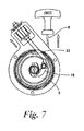
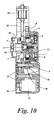
- Fig. 10 shows a starter provided with a sel-motor 31 as well as a starter rope 6 and a rope reel 3.
- An output gear 32 of the sel-motor 31 is meshes with a gear 34 formed on an outer periphery of a barrel 4, through a reduction gear 33 and a transmission gear 35.
- the reduction gear 33 and the transmission gear 35 are engaged with each other only when they are rotated in one direction.
- the sel-motor (self-starting-motor) 31 is operated, a rotational torque is transmitted to the barrel 4 from the reduction gear 33 to rotate the barrel 4.
- the rope reel 3 is rotated relatively in an opposite direction, and a one-way clutch 12 is disconnected and only the barrel 4 is rotated. Since a subsequent transmission of the rotation is the same as that described above, the same reference numerals are employed and an explanation is omitted.
- the stopper shaft 23 (pressing unit 40) is engaged with the regulating ratchet 18.
- the regulating ratchet 18 is operated by the accumulated rotational torque to be disengaged from the stopper shaft 23, and rotate the cam plate 5. Accordingly, a sufficient rotational torque (energy) is accumulated in the torque-accumulation spiral spring 10 irrespective of the variation in the rotational resistance of the engine so that the engine can be surely started.
- the stopper shaft 23 of the pressing unit 40 is held to be engaged with the regulating ratchet 18 against the resilient force of the torque-accumulation spiral spring 10 until the rotational torque necessary for starting the engine is accumulated in the torque-accumulation spiral spring 10. After the stopper shaft 23 is moved to a position where the stopper shaft is disengaged from the regulating ratchet 18, the stopper shaft 23 is moved to return to a stand-by position by the coil spring 24. Thus, after the engine is started, the stopper shaft 23 does not need to be externally operated to return to the stand-by position.
- the sel-motor may be used.
- the clutch mechanism between the cam plate 5 and the driving pulley 11 includes the centrifugal ratchet 16 and the cam pawl 15, however, the clutch mechanism is not limited thereto.
- a friction type clutch mechanism may be used.
- a coil spring may be used in place of the torque-accumulation spiral spring.
Landscapes
- Engineering & Computer Science (AREA)
- Chemical & Material Sciences (AREA)
- Combustion & Propulsion (AREA)
- Mechanical Engineering (AREA)
- General Engineering & Computer Science (AREA)
- One-Way And Automatic Clutches, And Combinations Of Different Clutches (AREA)
- Transmission Devices (AREA)
- Braking Arrangements (AREA)
- Springs (AREA)
Applications Claiming Priority (2)
| Application Number | Priority Date | Filing Date | Title |
|---|---|---|---|
| JP2009199099 | 2009-08-29 | ||
| JP2009254626A JP5428093B2 (ja) | 2009-08-29 | 2009-11-06 | 小型エンジンの始動装置 |
Publications (3)
| Publication Number | Publication Date |
|---|---|
| EP2299103A2 true EP2299103A2 (de) | 2011-03-23 |
| EP2299103A3 EP2299103A3 (de) | 2012-04-18 |
| EP2299103B1 EP2299103B1 (de) | 2020-03-18 |
Family
ID=42938231
Family Applications (1)
| Application Number | Title | Priority Date | Filing Date |
|---|---|---|---|
| EP10174166.8A Active EP2299103B1 (de) | 2009-08-29 | 2010-08-26 | Seilstarter |
Country Status (4)
| Country | Link |
|---|---|
| US (1) | US8616170B2 (de) |
| EP (1) | EP2299103B1 (de) |
| JP (1) | JP5428093B2 (de) |
| CN (1) | CN102003321B (de) |
Families Citing this family (7)
| Publication number | Priority date | Publication date | Assignee | Title |
|---|---|---|---|---|
| JP5515045B2 (ja) * | 2010-01-29 | 2014-06-11 | スターテング工業株式会社 | 小型エンジンの始動装置 |
| CN102588181A (zh) * | 2012-03-13 | 2012-07-18 | 山东华盛农业药械有限责任公司 | 反冲起动器 |
| DE102013011978B3 (de) * | 2013-07-18 | 2014-11-06 | Andreas Reichart | Anlassereinheit für ein mobiles Gerät mit einer Verbrennungskraftmaschine |
| JP6509530B2 (ja) * | 2014-11-19 | 2019-05-08 | スターテング工業株式会社 | リコイルスタータ |
| US10519865B2 (en) * | 2016-06-17 | 2019-12-31 | Ge Aviation Systems Llc | Air turbine starter with decoupler |
| US10961969B2 (en) * | 2017-09-01 | 2021-03-30 | Honda Motor Co., Ltd. | Startup assistance device for internal combustion engine |
| JP7061311B2 (ja) * | 2018-04-20 | 2022-04-28 | スターテング工業株式会社 | エンジンの始動装置 |
Citations (1)
| Publication number | Priority date | Publication date | Assignee | Title |
|---|---|---|---|---|
| JP2002227753A (ja) | 2001-01-31 | 2002-08-14 | Starting Ind Co Ltd | エンジンの始動装置 |
Family Cites Families (14)
| Publication number | Priority date | Publication date | Assignee | Title |
|---|---|---|---|---|
| US4167929A (en) * | 1977-09-07 | 1979-09-18 | Outboard Marine Corporation | Engine including speed-control starter interlock |
| US4582030A (en) * | 1984-03-02 | 1986-04-15 | Tecumseh Products Company | Mounting recoil starter |
| US5083534A (en) | 1989-04-05 | 1992-01-28 | Mitsubishi Jukogyo Kabushiki Kaisha | Spiral spring type starter apparatus for an internal combustion engine |
| US6508220B1 (en) | 1999-08-25 | 2003-01-21 | Kioritz Corporation | Starter |
| JP4017792B2 (ja) * | 1999-08-25 | 2007-12-05 | 株式会社共立 | 蓄力式スタータ装置 |
| CN100523481C (zh) * | 2002-10-21 | 2009-08-05 | 开始工业株式会社 | 一种反冲起动器 |
| JP4014998B2 (ja) * | 2002-10-21 | 2007-11-28 | スターテング工業株式会社 | リコイルスタータ |
| JP3878564B2 (ja) | 2003-02-28 | 2007-02-07 | スターテング工業株式会社 | 蓄力式リコイルスタータ |
| JP2004285875A (ja) * | 2003-03-20 | 2004-10-14 | Kubota Corp | エンジンのリコイルスタータ |
| JP4540576B2 (ja) * | 2004-09-24 | 2010-09-08 | 昭和機器工業株式会社 | ロック式蓄力スタータ装置 |
| JP4667125B2 (ja) | 2005-06-08 | 2011-04-06 | スターテング工業株式会社 | 小型エンジンの始動装置 |
| EP1965073B1 (de) | 2005-12-20 | 2016-07-06 | Husqvarna Zenoah Co., Ltd. | Motorstartvorrichtung |
| JP4792408B2 (ja) * | 2007-01-24 | 2011-10-12 | スターテング工業株式会社 | リコイルスタータ |
| JP5515045B2 (ja) * | 2010-01-29 | 2014-06-11 | スターテング工業株式会社 | 小型エンジンの始動装置 |
-
2009
- 2009-11-06 JP JP2009254626A patent/JP5428093B2/ja active Active
-
2010
- 2010-08-25 US US12/868,006 patent/US8616170B2/en active Active
- 2010-08-26 EP EP10174166.8A patent/EP2299103B1/de active Active
- 2010-08-30 CN CN201010268867.7A patent/CN102003321B/zh active Active
Patent Citations (1)
| Publication number | Priority date | Publication date | Assignee | Title |
|---|---|---|---|---|
| JP2002227753A (ja) | 2001-01-31 | 2002-08-14 | Starting Ind Co Ltd | エンジンの始動装置 |
Also Published As
| Publication number | Publication date |
|---|---|
| CN102003321B (zh) | 2014-12-03 |
| EP2299103A3 (de) | 2012-04-18 |
| US20110048361A1 (en) | 2011-03-03 |
| CN102003321A (zh) | 2011-04-06 |
| JP5428093B2 (ja) | 2014-02-26 |
| EP2299103B1 (de) | 2020-03-18 |
| JP2011069347A (ja) | 2011-04-07 |
| US8616170B2 (en) | 2013-12-31 |
Similar Documents
| Publication | Publication Date | Title |
|---|---|---|
| EP2299103A2 (de) | Seilstarter | |
| US6508220B1 (en) | Starter | |
| US6901899B2 (en) | Recoil starter | |
| EP1865196B1 (de) | Kraftübertragungsmechanismus zwischen anlasser und motor | |
| EP2647829B1 (de) | Rückstoss-startvorrichtung | |
| EP1950413A2 (de) | Rückschlagstarter | |
| EP3084205B1 (de) | Startervorrichtung für einen verbrennungsmotor | |
| EP2365208B1 (de) | Anlasser für einen kleinen Motor | |
| JP3878564B2 (ja) | 蓄力式リコイルスタータ | |
| EP2218907B1 (de) | Seilstarter | |
| EP1253315A3 (de) | Startvorrichtungen für Brennkraftmaschinen | |
| EP3023629B1 (de) | Seilzugstarter | |
| JP5314572B2 (ja) | ウエビング巻取装置 | |
| JP3892771B2 (ja) | リコイルスタータ | |
| JP2003314582A (ja) | 過負荷クラッチ機構 | |
| JP5269682B2 (ja) | 小型エンジンの始動装置 | |
| JPH03258969A (ja) | 小型エンジンの始動装置 | |
| JP2003343402A (ja) | リコイルスタータ |
Legal Events
| Date | Code | Title | Description |
|---|---|---|---|
| PUAI | Public reference made under article 153(3) epc to a published international application that has entered the european phase |
Free format text: ORIGINAL CODE: 0009012 |
|
| AK | Designated contracting states |
Kind code of ref document: A2 Designated state(s): AL AT BE BG CH CY CZ DE DK EE ES FI FR GB GR HR HU IE IS IT LI LT LU LV MC MK MT NL NO PL PT RO SE SI SK SM TR |
|
| AX | Request for extension of the european patent |
Extension state: BA ME RS |
|
| PUAL | Search report despatched |
Free format text: ORIGINAL CODE: 0009013 |
|
| AK | Designated contracting states |
Kind code of ref document: A3 Designated state(s): AL AT BE BG CH CY CZ DE DK EE ES FI FR GB GR HR HU IE IS IT LI LT LU LV MC MK MT NL NO PL PT RO SE SI SK SM TR |
|
| AX | Request for extension of the european patent |
Extension state: BA ME RS |
|
| RIC1 | Information provided on ipc code assigned before grant |
Ipc: F02N 5/02 20060101ALI20120309BHEP Ipc: F02N 3/02 20060101AFI20120309BHEP |
|
| 17P | Request for examination filed |
Effective date: 20121012 |
|
| 17Q | First examination report despatched |
Effective date: 20160704 |
|
| RIC1 | Information provided on ipc code assigned before grant |
Ipc: F02N 5/02 20060101ALI20190211BHEP Ipc: F02N 3/02 20060101AFI20190211BHEP Ipc: F02N 15/02 20060101ALN20190211BHEP |
|
| RIC1 | Information provided on ipc code assigned before grant |
Ipc: F02N 15/02 20060101ALN20190219BHEP Ipc: F02N 3/02 20060101AFI20190219BHEP Ipc: F02N 5/02 20060101ALI20190219BHEP |
|
| STAA | Information on the status of an ep patent application or granted ep patent |
Free format text: STATUS: EXAMINATION IS IN PROGRESS |
|
| RIC1 | Information provided on ipc code assigned before grant |
Ipc: F02N 5/02 20060101ALI20190925BHEP Ipc: F02N 3/02 20060101AFI20190925BHEP Ipc: F02N 15/02 20060101ALN20190925BHEP |
|
| GRAP | Despatch of communication of intention to grant a patent |
Free format text: ORIGINAL CODE: EPIDOSNIGR1 |
|
| STAA | Information on the status of an ep patent application or granted ep patent |
Free format text: STATUS: GRANT OF PATENT IS INTENDED |
|
| INTG | Intention to grant announced |
Effective date: 20191108 |
|
| GRAS | Grant fee paid |
Free format text: ORIGINAL CODE: EPIDOSNIGR3 |
|
| GRAA | (expected) grant |
Free format text: ORIGINAL CODE: 0009210 |
|
| STAA | Information on the status of an ep patent application or granted ep patent |
Free format text: STATUS: THE PATENT HAS BEEN GRANTED |
|
| AK | Designated contracting states |
Kind code of ref document: B1 Designated state(s): AL AT BE BG CH CY CZ DE DK EE ES FI FR GB GR HR HU IE IS IT LI LT LU LV MC MK MT NL NO PL PT RO SE SI SK SM TR |
|
| REG | Reference to a national code |
Ref country code: GB Ref legal event code: FG4D |
|
| REG | Reference to a national code |
Ref country code: SE Ref legal event code: TRGR |
|
| REG | Reference to a national code |
Ref country code: DE Ref legal event code: R096 Ref document number: 602010063524 Country of ref document: DE |
|
| REG | Reference to a national code |
Ref country code: AT Ref legal event code: REF Ref document number: 1246180 Country of ref document: AT Kind code of ref document: T Effective date: 20200415 Ref country code: IE Ref legal event code: FG4D |
|
| PG25 | Lapsed in a contracting state [announced via postgrant information from national office to epo] |
Ref country code: NO Free format text: LAPSE BECAUSE OF FAILURE TO SUBMIT A TRANSLATION OF THE DESCRIPTION OR TO PAY THE FEE WITHIN THE PRESCRIBED TIME-LIMIT Effective date: 20200618 Ref country code: FI Free format text: LAPSE BECAUSE OF FAILURE TO SUBMIT A TRANSLATION OF THE DESCRIPTION OR TO PAY THE FEE WITHIN THE PRESCRIBED TIME-LIMIT Effective date: 20200318 |
|
| REG | Reference to a national code |
Ref country code: NL Ref legal event code: MP Effective date: 20200318 |
|
| PG25 | Lapsed in a contracting state [announced via postgrant information from national office to epo] |
Ref country code: BG Free format text: LAPSE BECAUSE OF FAILURE TO SUBMIT A TRANSLATION OF THE DESCRIPTION OR TO PAY THE FEE WITHIN THE PRESCRIBED TIME-LIMIT Effective date: 20200618 Ref country code: GR Free format text: LAPSE BECAUSE OF FAILURE TO SUBMIT A TRANSLATION OF THE DESCRIPTION OR TO PAY THE FEE WITHIN THE PRESCRIBED TIME-LIMIT Effective date: 20200619 Ref country code: LV Free format text: LAPSE BECAUSE OF FAILURE TO SUBMIT A TRANSLATION OF THE DESCRIPTION OR TO PAY THE FEE WITHIN THE PRESCRIBED TIME-LIMIT Effective date: 20200318 Ref country code: HR Free format text: LAPSE BECAUSE OF FAILURE TO SUBMIT A TRANSLATION OF THE DESCRIPTION OR TO PAY THE FEE WITHIN THE PRESCRIBED TIME-LIMIT Effective date: 20200318 |
|
| REG | Reference to a national code |
Ref country code: LT Ref legal event code: MG4D |
|
| PG25 | Lapsed in a contracting state [announced via postgrant information from national office to epo] |
Ref country code: NL Free format text: LAPSE BECAUSE OF FAILURE TO SUBMIT A TRANSLATION OF THE DESCRIPTION OR TO PAY THE FEE WITHIN THE PRESCRIBED TIME-LIMIT Effective date: 20200318 |
|
| PG25 | Lapsed in a contracting state [announced via postgrant information from national office to epo] |
Ref country code: LT Free format text: LAPSE BECAUSE OF FAILURE TO SUBMIT A TRANSLATION OF THE DESCRIPTION OR TO PAY THE FEE WITHIN THE PRESCRIBED TIME-LIMIT Effective date: 20200318 Ref country code: SK Free format text: LAPSE BECAUSE OF FAILURE TO SUBMIT A TRANSLATION OF THE DESCRIPTION OR TO PAY THE FEE WITHIN THE PRESCRIBED TIME-LIMIT Effective date: 20200318 Ref country code: IS Free format text: LAPSE BECAUSE OF FAILURE TO SUBMIT A TRANSLATION OF THE DESCRIPTION OR TO PAY THE FEE WITHIN THE PRESCRIBED TIME-LIMIT Effective date: 20200718 Ref country code: RO Free format text: LAPSE BECAUSE OF FAILURE TO SUBMIT A TRANSLATION OF THE DESCRIPTION OR TO PAY THE FEE WITHIN THE PRESCRIBED TIME-LIMIT Effective date: 20200318 Ref country code: CZ Free format text: LAPSE BECAUSE OF FAILURE TO SUBMIT A TRANSLATION OF THE DESCRIPTION OR TO PAY THE FEE WITHIN THE PRESCRIBED TIME-LIMIT Effective date: 20200318 Ref country code: PT Free format text: LAPSE BECAUSE OF FAILURE TO SUBMIT A TRANSLATION OF THE DESCRIPTION OR TO PAY THE FEE WITHIN THE PRESCRIBED TIME-LIMIT Effective date: 20200812 Ref country code: EE Free format text: LAPSE BECAUSE OF FAILURE TO SUBMIT A TRANSLATION OF THE DESCRIPTION OR TO PAY THE FEE WITHIN THE PRESCRIBED TIME-LIMIT Effective date: 20200318 Ref country code: SM Free format text: LAPSE BECAUSE OF FAILURE TO SUBMIT A TRANSLATION OF THE DESCRIPTION OR TO PAY THE FEE WITHIN THE PRESCRIBED TIME-LIMIT Effective date: 20200318 |
|
| REG | Reference to a national code |
Ref country code: AT Ref legal event code: MK05 Ref document number: 1246180 Country of ref document: AT Kind code of ref document: T Effective date: 20200318 |
|
| REG | Reference to a national code |
Ref country code: DE Ref legal event code: R097 Ref document number: 602010063524 Country of ref document: DE |
|
| PLBE | No opposition filed within time limit |
Free format text: ORIGINAL CODE: 0009261 |
|
| STAA | Information on the status of an ep patent application or granted ep patent |
Free format text: STATUS: NO OPPOSITION FILED WITHIN TIME LIMIT |
|
| PG25 | Lapsed in a contracting state [announced via postgrant information from national office to epo] |
Ref country code: DK Free format text: LAPSE BECAUSE OF FAILURE TO SUBMIT A TRANSLATION OF THE DESCRIPTION OR TO PAY THE FEE WITHIN THE PRESCRIBED TIME-LIMIT Effective date: 20200318 Ref country code: ES Free format text: LAPSE BECAUSE OF FAILURE TO SUBMIT A TRANSLATION OF THE DESCRIPTION OR TO PAY THE FEE WITHIN THE PRESCRIBED TIME-LIMIT Effective date: 20200318 Ref country code: AT Free format text: LAPSE BECAUSE OF FAILURE TO SUBMIT A TRANSLATION OF THE DESCRIPTION OR TO PAY THE FEE WITHIN THE PRESCRIBED TIME-LIMIT Effective date: 20200318 |
|
| 26N | No opposition filed |
Effective date: 20201221 |
|
| PG25 | Lapsed in a contracting state [announced via postgrant information from national office to epo] |
Ref country code: PL Free format text: LAPSE BECAUSE OF FAILURE TO SUBMIT A TRANSLATION OF THE DESCRIPTION OR TO PAY THE FEE WITHIN THE PRESCRIBED TIME-LIMIT Effective date: 20200318 |
|
| PG25 | Lapsed in a contracting state [announced via postgrant information from national office to epo] |
Ref country code: MC Free format text: LAPSE BECAUSE OF FAILURE TO SUBMIT A TRANSLATION OF THE DESCRIPTION OR TO PAY THE FEE WITHIN THE PRESCRIBED TIME-LIMIT Effective date: 20200318 |
|
| REG | Reference to a national code |
Ref country code: CH Ref legal event code: PL |
|
| GBPC | Gb: european patent ceased through non-payment of renewal fee |
Effective date: 20200826 |
|
| PG25 | Lapsed in a contracting state [announced via postgrant information from national office to epo] |
Ref country code: LU Free format text: LAPSE BECAUSE OF NON-PAYMENT OF DUE FEES Effective date: 20200826 Ref country code: CH Free format text: LAPSE BECAUSE OF NON-PAYMENT OF DUE FEES Effective date: 20200831 Ref country code: LI Free format text: LAPSE BECAUSE OF NON-PAYMENT OF DUE FEES Effective date: 20200831 |
|
| REG | Reference to a national code |
Ref country code: BE Ref legal event code: MM Effective date: 20200831 |
|
| PG25 | Lapsed in a contracting state [announced via postgrant information from national office to epo] |
Ref country code: SI Free format text: LAPSE BECAUSE OF FAILURE TO SUBMIT A TRANSLATION OF THE DESCRIPTION OR TO PAY THE FEE WITHIN THE PRESCRIBED TIME-LIMIT Effective date: 20200318 |
|
| PG25 | Lapsed in a contracting state [announced via postgrant information from national office to epo] |
Ref country code: FR Free format text: LAPSE BECAUSE OF NON-PAYMENT OF DUE FEES Effective date: 20200831 |
|
| PG25 | Lapsed in a contracting state [announced via postgrant information from national office to epo] |
Ref country code: BE Free format text: LAPSE BECAUSE OF NON-PAYMENT OF DUE FEES Effective date: 20200831 Ref country code: GB Free format text: LAPSE BECAUSE OF NON-PAYMENT OF DUE FEES Effective date: 20200826 Ref country code: IE Free format text: LAPSE BECAUSE OF NON-PAYMENT OF DUE FEES Effective date: 20200826 |
|
| PG25 | Lapsed in a contracting state [announced via postgrant information from national office to epo] |
Ref country code: TR Free format text: LAPSE BECAUSE OF FAILURE TO SUBMIT A TRANSLATION OF THE DESCRIPTION OR TO PAY THE FEE WITHIN THE PRESCRIBED TIME-LIMIT Effective date: 20200318 Ref country code: MT Free format text: LAPSE BECAUSE OF FAILURE TO SUBMIT A TRANSLATION OF THE DESCRIPTION OR TO PAY THE FEE WITHIN THE PRESCRIBED TIME-LIMIT Effective date: 20200318 Ref country code: CY Free format text: LAPSE BECAUSE OF FAILURE TO SUBMIT A TRANSLATION OF THE DESCRIPTION OR TO PAY THE FEE WITHIN THE PRESCRIBED TIME-LIMIT Effective date: 20200318 |
|
| PG25 | Lapsed in a contracting state [announced via postgrant information from national office to epo] |
Ref country code: MK Free format text: LAPSE BECAUSE OF FAILURE TO SUBMIT A TRANSLATION OF THE DESCRIPTION OR TO PAY THE FEE WITHIN THE PRESCRIBED TIME-LIMIT Effective date: 20200318 Ref country code: AL Free format text: LAPSE BECAUSE OF FAILURE TO SUBMIT A TRANSLATION OF THE DESCRIPTION OR TO PAY THE FEE WITHIN THE PRESCRIBED TIME-LIMIT Effective date: 20200318 |
|
| PGFP | Annual fee paid to national office [announced via postgrant information from national office to epo] |
Ref country code: IT Payment date: 20230711 Year of fee payment: 14 |
|
| PGFP | Annual fee paid to national office [announced via postgrant information from national office to epo] |
Ref country code: SE Payment date: 20230630 Year of fee payment: 14 Ref country code: DE Payment date: 20230703 Year of fee payment: 14 |