EP2298601A2 - Scheinwerfersystem für ein Fahrzeug - Google Patents
Scheinwerfersystem für ein Fahrzeug Download PDFInfo
- Publication number
- EP2298601A2 EP2298601A2 EP10175509A EP10175509A EP2298601A2 EP 2298601 A2 EP2298601 A2 EP 2298601A2 EP 10175509 A EP10175509 A EP 10175509A EP 10175509 A EP10175509 A EP 10175509A EP 2298601 A2 EP2298601 A2 EP 2298601A2
- Authority
- EP
- European Patent Office
- Prior art keywords
- control
- vehicle
- ecu
- devices
- headlamp
- Prior art date
- Legal status (The legal status is an assumption and is not a legal conclusion. Google has not performed a legal analysis and makes no representation as to the accuracy of the status listed.)
- Granted
Links
Images


Classifications
-
- B—PERFORMING OPERATIONS; TRANSPORTING
- B60—VEHICLES IN GENERAL
- B60Q—ARRANGEMENT OF SIGNALLING OR LIGHTING DEVICES, THE MOUNTING OR SUPPORTING THEREOF OR CIRCUITS THEREFOR, FOR VEHICLES IN GENERAL
- B60Q1/00—Arrangement of optical signalling or lighting devices, the mounting or supporting thereof or circuits therefor
- B60Q1/02—Arrangement of optical signalling or lighting devices, the mounting or supporting thereof or circuits therefor the devices being primarily intended to illuminate the way ahead or to illuminate other areas of way or environments
- B60Q1/04—Arrangement of optical signalling or lighting devices, the mounting or supporting thereof or circuits therefor the devices being primarily intended to illuminate the way ahead or to illuminate other areas of way or environments the devices being headlights
- B60Q1/06—Arrangement of optical signalling or lighting devices, the mounting or supporting thereof or circuits therefor the devices being primarily intended to illuminate the way ahead or to illuminate other areas of way or environments the devices being headlights adjustable, e.g. remotely-controlled from inside vehicle
- B60Q1/076—Arrangement of optical signalling or lighting devices, the mounting or supporting thereof or circuits therefor the devices being primarily intended to illuminate the way ahead or to illuminate other areas of way or environments the devices being headlights adjustable, e.g. remotely-controlled from inside vehicle by electrical means including means to transmit the movements, e.g. shafts or joints
-
- B—PERFORMING OPERATIONS; TRANSPORTING
- B60—VEHICLES IN GENERAL
- B60Q—ARRANGEMENT OF SIGNALLING OR LIGHTING DEVICES, THE MOUNTING OR SUPPORTING THEREOF OR CIRCUITS THEREFOR, FOR VEHICLES IN GENERAL
- B60Q1/00—Arrangement of optical signalling or lighting devices, the mounting or supporting thereof or circuits therefor
- B60Q1/02—Arrangement of optical signalling or lighting devices, the mounting or supporting thereof or circuits therefor the devices being primarily intended to illuminate the way ahead or to illuminate other areas of way or environments
- B60Q1/04—Arrangement of optical signalling or lighting devices, the mounting or supporting thereof or circuits therefor the devices being primarily intended to illuminate the way ahead or to illuminate other areas of way or environments the devices being headlights
- B60Q1/06—Arrangement of optical signalling or lighting devices, the mounting or supporting thereof or circuits therefor the devices being primarily intended to illuminate the way ahead or to illuminate other areas of way or environments the devices being headlights adjustable, e.g. remotely-controlled from inside vehicle
- B60Q1/08—Arrangement of optical signalling or lighting devices, the mounting or supporting thereof or circuits therefor the devices being primarily intended to illuminate the way ahead or to illuminate other areas of way or environments the devices being headlights adjustable, e.g. remotely-controlled from inside vehicle automatically
- B60Q1/10—Arrangement of optical signalling or lighting devices, the mounting or supporting thereof or circuits therefor the devices being primarily intended to illuminate the way ahead or to illuminate other areas of way or environments the devices being headlights adjustable, e.g. remotely-controlled from inside vehicle automatically due to vehicle inclination, e.g. due to load distribution
-
- B—PERFORMING OPERATIONS; TRANSPORTING
- B60—VEHICLES IN GENERAL
- B60Q—ARRANGEMENT OF SIGNALLING OR LIGHTING DEVICES, THE MOUNTING OR SUPPORTING THEREOF OR CIRCUITS THEREFOR, FOR VEHICLES IN GENERAL
- B60Q1/00—Arrangement of optical signalling or lighting devices, the mounting or supporting thereof or circuits therefor
- B60Q1/02—Arrangement of optical signalling or lighting devices, the mounting or supporting thereof or circuits therefor the devices being primarily intended to illuminate the way ahead or to illuminate other areas of way or environments
- B60Q1/04—Arrangement of optical signalling or lighting devices, the mounting or supporting thereof or circuits therefor the devices being primarily intended to illuminate the way ahead or to illuminate other areas of way or environments the devices being headlights
- B60Q1/06—Arrangement of optical signalling or lighting devices, the mounting or supporting thereof or circuits therefor the devices being primarily intended to illuminate the way ahead or to illuminate other areas of way or environments the devices being headlights adjustable, e.g. remotely-controlled from inside vehicle
- B60Q1/08—Arrangement of optical signalling or lighting devices, the mounting or supporting thereof or circuits therefor the devices being primarily intended to illuminate the way ahead or to illuminate other areas of way or environments the devices being headlights adjustable, e.g. remotely-controlled from inside vehicle automatically
- B60Q1/12—Arrangement of optical signalling or lighting devices, the mounting or supporting thereof or circuits therefor the devices being primarily intended to illuminate the way ahead or to illuminate other areas of way or environments the devices being headlights adjustable, e.g. remotely-controlled from inside vehicle automatically due to steering position
-
- B—PERFORMING OPERATIONS; TRANSPORTING
- B60—VEHICLES IN GENERAL
- B60Q—ARRANGEMENT OF SIGNALLING OR LIGHTING DEVICES, THE MOUNTING OR SUPPORTING THEREOF OR CIRCUITS THEREFOR, FOR VEHICLES IN GENERAL
- B60Q2200/00—Special features or arrangements of vehicle headlamps
- B60Q2200/30—Special arrangements for adjusting headlamps, e.g. means for transmitting the movements for adjusting the lamps
- B60Q2200/38—Automatic calibration of motor-driven means for adjusting headlamps, i.e. when switching on the headlamps, not during mounting at factories
Definitions
- the present disclosure relates to a headlamp of a vehicle such as an automobile and, more particularly, to a vehicle headlamp system configured to automatically control and change a light irradiation condition, such as a light irradiation direction, of a headlamp.
- a related art headlamp system is configured to automatically control a light irradiation direction of a headlamp to enhance traveling safety of a vehicle.
- the system includes a leveling device configured to control and change the light irradiation direction of the headlamp in a vertical direction in accordance with variations in a pitch angle of the vehicle (i.e., an inclination angle of the vehicle along a front-rear direction of the vehicle) which may be caused by a change of occupants or a change of a load carried on the vehicle.
- the system also may be include a swiveling device configured to control and change the light irradiation direction of the headlamp in a horizontal direction so as to follow variations in a steering angle.
- the swiveling device includes a cornering lamp device having multiple lamp units in the headlamp and configured to automatically turn on or off of the lamp units to control and substantially change the light irradiation direction of the headlamp in the horizontal direction.
- the system may also include a lamp headlamp cleaner configured to automatically clean a front cover of the headlamp.
- the headlamp system having such multiple of functions includes an electronic control unit (ECU) for centralized control of the respective functions.
- the ECU is programmed to carry out the respective functions. More specifically, the ECU is configured to detect variations in the pitch angle, the steering angle, and/or dirt on the headlamp and to automatically control, based on the detected data, the leveling device, the swiveling device and/or the lamp headlamp cleaner.
- the vehicle type differs depending on grade and specifications of the vehicle and, if the ECU is prepared for each type of vehicle, manufacture and management of the ECUs become onerous.
- an ECU of a generalized type This type of ECU is installed with a program that can be commonly used for different types of vehicle. Vehicle constants, which differ for each type of vehicle, are stored in a memory of the ECU in advance, so that a vehicle constant that corresponds to the type of vehicle to be controlled can be selected to carry out a normal control corresponding to the vehicle type.
- a related art auto-leveling system for a vehicle headlamp uses such an ECU.
- a specification signal for selecting a vehicle constant that corresponds to a vehicle type is entered into the ECU
- a specification signal recognition section of the ECU recognizes the vehicle type
- the ECU transmits a specification signal that corresponds to the recognized vehicle type to the outside for verification (see, e.g., JP 2006-160036 A ).
- Some ECUs of this type have a diagnosis communication function. By using the diagnosis communication function, reception and transmission of the specification signals are carried out.
- the ECU having the diagnosis communication function obtains error codes (i.e., diagnostic trouble codes (DTCs) during a self-diagnostic operation), and stores the DTCs in a memory, and reads the DTCs when needed.
- DTCs diagnostic trouble codes
- These codes are specific to different types of vehicle. Therefore, when specifications of a vehicle are changed as the result of an addition or replacement of options to the vehicle and thus the vehicle is treated as a different type, the DTCs stored before the change of specification become inconsistent, which may cripple the system. This is not limited to the error codes.
- an ECU stores initial setting values serving as reference values for control, such as a reference vehicle height for initializing a leveling device, a reference steering angle for initializing a swiveling device, and a dirt reference value for initializing a headlamp cleaner
- initial setting values serving as reference values for control
- specifications of the vehicle are changed (e.g., added, deleted or replaced).
- the initial setting values previously stored in the memory of the ECU and new initial setting values to be newly set for the changed specifications may interfere with each other, which may cause a problem in the system.
- the ECU may be reset when the vehicle type is changed so as to clear the error codes and initial setting values stored in the memory, and store new error codes and initial setting values that correspond to the current vehicle type.
- the system cannot be operated until storage of all initial setting values necessary for the system is completed.
- normal control operations of the system are stopped. For example, the normal control operation by the leveling device is stopped until a reference vehicle height is initialized, the normal control operation by the swiveling device is stopped until a reference steering angle is initialized, and the normal control operation by the headlamp cleaner is stopped until a dirt reference value is initialized. Therefore, the normal control operations by the leveling device and swiveling device are stopped until the initializations of the reference vehicle height and the reference steering angle are completed and thus, during such time, the operations of the entire system is stopped. Accordingly, recovery of the system takes time.
- Sensors such as a vehicle height sensor and a steering angle sensor are coupled to the ECU to detect the pitch angle and the steering angle. Based on detection outputs from the sensors, the ECU controls, for example, the leveling device and the swiveling device.
- the system may be configured to carry out a failsafe operation such that the ECU monitors the outputs from the respective sensors and, when the ECU determines that sensor outputs are abnormal, control operations of the leveling device and the swiveling device are stopped. However, when it is determined for example that the steering angle sensor is abnormal, control operation of the swiveling device and also control operation of the leveling device, which may not be associated with the steering operation, are stopped. In other words the entire system is stopped, until the steering angle sensor is recovered.
- Illustrative aspects of the invention provide a vehicle headlamp system configured to avoid breakdown of the entire system, enable a quick recovery of the system, and ensure a normal operation of the system.
- a vehicle headlamp system includes a headlamp having control devices, and an ECU configured to control the control devices respectively.
- Each of the control devices is configured to control and change a light irradiation condition of the headlamp.
- the ECU stores vehicle constants, error code information and initialization information corresponding to different types of vehicles, respectively, and controls the control devices in accordance with the stored information.
- the ECU selects at least one of the vehicle constants that corresponds to the changed vehicle type, clears the stored error code information and the initialization information after selecting the vehicle constant(s), stores initialization information that corresponds to the changed vehicle type in accordance with the selected vehicle constant(s), and initializes the control devices in accordance with the stored initialization information.
- the ECU is configured to recognize dependencies between the control devices and, if the control devices include a first control device that is independent, the ECU executes a normal control by the first control device directly after initializing the first control device.
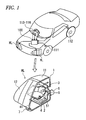
- Fig. 1 is a schematic view of the configuration of a vehicle having a headlamp system according to an example of the invention
- a vehicle headlamp system includes a headlamp having multiple control devices, and an ECU configured to control the control devices respectively.
- Each of the control devices is configured to control and change a light irradiation condition of the headlamp.
- the ECU stores vehicle constants, error code information and initialization information corresponding to different types of vehicle respectively, and controls the control devices in accordance with the stored information.
- the ECU selects at least one of the vehicle constants that corresponds to the changed vehicle type, clears the stored error code information and the initialization information after selecting the one or more vehicle constants, stores initialization information that corresponds to the changed vehicle type in accordance with the selected vehicle constant(s), and initializes the control devices in accordance with the stored initialization information.
- the ECU is configured to recognize dependencies between the control devices and, if the control devices include a first control device that is independent, the ECU executes a normal control by the first control device directly after initializing the first control device.
- control devices include a second control device that is dependent on another of the control devices
- the ECU stops normal control by the second control device until initialization of the other control device is completed.
- control devices can include a leveling device configured to control and change a light irradiation direction of the headlamp in up and down directions and a swiveling device configured to control and change the light irradiation direction in right and left directions.
- the ECU can be configured to recognize the leveling device as the first control device, and recognize the swiveling device as the second control device that is dependent on the leveling device such that normal control by the swiveling device is stopped until initialization of the leveling device is completed. In this case, normal control by the leveling device is carried out even when initialization of the swivel device is not yet completed.
- the vehicle headlamp system can further include multiple control-related devices respectively related to at least one of the control devices.
- the ECU can be configured to check whether each of the control-related devices is normal or abnormal, and to check dependencies of each of the control devices on the respective control-related devices such that, if one of the control devices is not dependent on one of the control-related devices, normal control by the one of the control devices is carried out irrespective of whether the one of the control-related devices is normal or abnormal.
- headlamps HL are mounted on right and left sides of a front portion of the vehicle respectively.
- Each of the headlamps HL has multiple control devices to control and change light irradiation conditions of the headlamp HL such as a light irradiation direction of the headlamp HL.
- the control devices include a leveling device configured to control and change a lamp optical axis of the headlamp HL in up and down directions, a swiveling device configured to control and change the lamp optical axis of the headlamp HL in right and left directions, and a headlamp cleaner configured to clean away dirt, such as mud, stuck to the front cover of the headlamp HL.
- Fig. 1 shows a typical section configuration of the left headlamp HL, a lamp body 11 and a transparent front cover 12 cooperate together in constituting a lamp housing 1.
- a bracket 2 which can be inclined in the vertical direction and, on the bracket 2, there is supported a reflector 3.
- a swivel actuator 4 having an output shaft 41 rotatable in the horizontal direction.
- the drive shaft 41 is connected to the reflector 3, thereby constituting a swiveling device which can deflect the reflector 3 in the horizontal direction.
- a light source 6 is supported on the reflector 3.
- the light source 6 can be a light bulb or any other kind of suitable light source.
- the lower portion of the bracket 2 is connected to a drive rod 51 provided on the leveling actuator 5.
- the bracket 2 can be inclined in the vertical direction and, with the inclining movement of the bracket 2, the reflector 3 can be inclined in the vertical direction integrally with the bracket 2, thereby constituting a leveling device which is used to deflect the lamp optical axis in the vertical direction.
- an ejection nozzle 7 for ejecting cleaning water.
- the ejection nozzle 7 is configured as a headlamp cleaner which, when a cleaning pump having a headlamp cleaner motor (not shown) serving as a drive source is driven, ejects the cleaning water toward the front cover 12 to clean mud or the like stuck to the surface of the front cover 12.
- a cornering lamp configured such that multiple lamp units are mounted within a lamp housing. These lamp units are turned on selectively or simultaneously to change the light irradiation area of the headlamp. Since such cornering lamp can have a function similar to a swiveling device for deflecting the lamp optical axis in the horizontal direction, this cornering lamp is regarded as an example of a swiveling device here.
- the ECU 100 includes: a microprocessor (which is hereinafter referred to as a CPU) 101; a nonvolatile memory 102 (e.g., a flash ROM) for storing a control program for operating the CPU 101 and also for storing type information; and a RAM 103 which stores information about the control.
- a microprocessor which is hereinafter referred to as a CPU
- nonvolatile memory 102 e.g., a flash ROM
- RAM 103 which stores information about the control.
- the ECU 100 further includes an output interface (output 1/F) 104 for providing control information for control of these devices and input interface (input 1/F) 105 for entering various kinds of information from control-related devices.
- the above-mentioned control-related devices are for detecting information according to which the ECU 100 can carry out it control operations, or for entering and providing information about an error code and the like.
- the former control-related device as shown in Fig. 1 as well, there are available a front vehicle height sensor 111 for detecting the vehicle height in the front wheel of the vehicle, and a rear vehicle height sensor 112 for detecting the vehicle height in the rear wheel of the vehicle.
- a steering angle sensor 113 for detecting a steering angle corresponding to the steering operation of a driver
- a vehicle speed sensor 114 for detecting the running speed of the vehicle.
- a lamp switch sensor 115 for detecting the state of a headlamp switch to be operated by the driver
- a washer switch sensor 116 for detecting the state of a washer switch to be operated when cleaning a front glass.
- a diagnosis I/F 117 which is interposed between the ECU 100 and a tester connected to the outside for entering an error code showing the fault history of a vehicle incorporating the ECU 100 therein.
- the nonvolatile memory 102 stores, as the type information, vehicle constants specific to individual types of vehicle, initial setting values, and error codes.
- the vehicle constants are constants which are specific to individual types of vehicle.
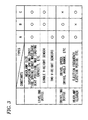
- Fig. 3 shows examples of the vehicle constants when vehicle types A, B and C are applicable.
- type A uses all functions of the leveling device 5, swiveling device 4 and headlamp cleaner 7.
- vehicle constants which correspond to the respective devices, are entered.
- a circle indicates that the vehicle constant is entered.
- Type B has the functions of the leveling device and swiveling device.
- vehicle constants are entered.
- a vehicle constant in not entered instead, a default value is entered.
- an x mark shows that a default value is entered.
- Type C has the functions of the leveling device and headlamp cleaner.
- the leveling device 5 is influenced by the dimensions of headlamps, the spring constants of the suspension and tire of a vehicle, the wheelbase of a vehicle, the seat positions of a vehicle, and the maximum loading capacity of a vehicle, in the leveling device 5, the values of these items are stored as the vehicle constants for every type of vehicle. Also, a difference between a one-vehicle-height-sensor system and a two-vehicle-height-sensor system is stored as a vehicle constant.
- type A is set as a two-vehicle-height-sensor system, whereas types of vehicles B and C are respectively set as a one-vehicle-height-sensor system.
- the swivel control characteristics of vehicles such as the swivel speeds and swivel angle ranges of vehicles differ from each other depending on whether each of the vehicles is a sports vehicle, a high-class vehicle, a family vehicle, a commercial vehicle or the like, the values of these characteristics are stored as constants.
- the headlamp cleaner 7 since the ejection frequency of cleaning water and the time of ejection of cleaning water from the ejection nozzle are influenced by the dimensions of headlamps, especially by the dimension of the front covers of the headlamps, the values of these dimensions are stored for every type of vehicle. These vehicle constants are to be stored in advance in accordance with the respective types of vehicles in which the present ECU is incorporated.
- Initial setting values to be stored in the nonvolatile memory 102 are set values which are used as reference values when initializing the leveling devices 5, swiveling devices 4 and headlamp cleaners 7 of the respective types of vehicle.
- the CPU 101 reads out the vehicle set values of the respective types of vehicles from the nonvolatile memory 102 and, according to the read vehicle set values, carries out a necessary operation. Then, the obtained initial setting values are stored into the nonvolatile memory 102.
- initializing operations for example, an operation to initialize the vehicle height value in the leveling device 5, and an operation to initialize the center position of the steering angle in the swiveling device 4.
- codes related to the histories of faults such as failures, defects and abnormalities, which have been detected when the ECU 100 carries out a self-diagnostic operation may be stored into the nonvolatile memory 102 in such a manner that they correspond to their respective types of vehicle.
- numeric value relating to the control that corresponds to this type can be set in such a manner that, for example, an operator enters it into the RAM 103 directly.
- numeric values corresponding to the respective types of vehicle also can be stored into the nonvolatile memory 102 in advance and, when a certain type is set, a corresponding numeric value can be read out selectively from the nonvolatile memory 102 and then can be set into the RAM 103.
- Such numeric values are used as coefficients or the like, for example, in an operation equation which is used to operate initial setting values according to vehicle constants.
- the nonvolatile memory 102 there is set a vehicle constant corresponding to a type in which the present ECU 100 is incorporated.
- the RAM 103 there is set a numeric value relating to the control that corresponds to this type.
- the CPU 101 operates an initial setting value according to the vehicle constant and the numeric value relating to the control, and stores the operation result into the nonvolatile memory 102.
- the CPU 101 initializes the necessary one of the leveling device 5, swiveling device 4 and headlamp cleaner 7 according to the stored initial setting value. As a result of this, the deflection angles of the lamp optical axis of the headlamp HL in the vertical and horizontal directions are respectively oriented toward the initial set angles. Also, in the headlamp cleaner 7, there are set the ejection frequency and the time of ejection of cleaning water from the ejection nozzle in the cleaning operation.
- the ECU 100 enters therein the detection outputs of the control-related devices, that is, the front vehicle height sensor 111, rear vehicle height sensor 112, steering angle sensor 113, vehicle speed sensor 114, lamp switch sensor 115 and washer switch sensor 116.
- the ECU 100 carries out a necessary control operation according to the entered detection outputs, and carries out normal control operations on the leveling device 5, swiveling device 4 and headlamp cleaner 7 according to the results of the control operation.
- the leveling actuator is feed-back controlled following variations in the pitch angle of a vehicle.
- a control operation is carried out in which the lamp optical axis of the headlamp HL is held at a given angle in the vertical direction with respect to a road surface regardless of the pitch angle variations.
- the swivel actuator is feed-back controlled following the steering angle of a vehicle, thereby controlling and deflecting the lamp optical axis of the headlamp HL in the horizontal direction.
- the headlamp cleaner 7 according to the output of the washer switch sensor 116 when washing the windshield of a vehicle, the cleaning water is ejected from the ejection nozzle onto the front cover 12 of the headlamp HL to thereby clean the front cover 12.
- the ECU constantly monitors the control-related devices and checks whether these control-related devices are normal or abnormal.
- the ECU is configured such that, when it detects any abnormal state, it can set a failsafe state so as to stop normal control operations of the control devices that are related to the abnormal control-related devices.
- the change of type C to type A is set in the ECU 100.
- the CPU 101 selects the vehicle constant of type A from the vehicle constants stored in the nonvolatile memory 102. Also, simultaneously with this, the CPU 101 sets a numeric value related to the control corresponding to type A into the RAM 103. From now on, according to the vehicle constant of type A and the control-related value, initialization and normal control operation are carried out. Also, in this normal control operation, a self-diagnosis operation is carried out through the diagnosis I/F 117.
- the changed vehicle type may not be matched to the error code stored in the nonvolatile memory 102; or, the initial setting value stored in the nonvolatile memory 102 and an initial setting value to be newly set relating to the changed vehicle type may interfere with each other.
- the system is configured such that, after the leveling device 5, swiveling device 4 and headlamp cleaner 7 are all initialized, control operation by the ECU 100 can be carried out, during such initialization, the control operation of the ECU 100 (i.e., operation of the entire system) is stopped as described above. Similarly, when the control-related devices are found to be abnormal, the entire system is stopped as described above.
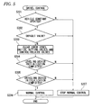
- a vehicle constant is newly selected or not when the type is changed (S101). If not selected, normal control operations of the leveling device 5, swiveling device 4 and headlamp cleaner 7 are stopped (S110). Even when the vehicle constant is selected, it is checked whether the selected vehicle constant is a specific value or a default value (S102). If the default value is found, normal control operations of the respective devices are stopped similarly (S110).
- the error code and initial setting value stored in the nonvolatile memory 102 are cleared and, at the same time, a numeric value, which is set in the RAM 103 and is related to the control operation, is cleared (S103).
- the CPU 101 checks a device to be controlled for its dependency (S104).
- the leveling device 5, swiveling device 4 and headlamp cleaner 7 are checked to determine whether or not one of them to be controlled is dependent on the other.
- the swiveling device 4 may swivel in a state where the lamp optical axis thereof faces upward. Therefore, the swiveling device 4 is dependent on the leveling device 5.
- the leveling device 5 is controlled in a state where the deflecting position in the horizontal direction of the lamp optical axis is set at any angle position a problem in the leveling device 5 does not arise.
- the leveling device 5 has no connection with the control of the headlamp cleaner 7. Therefore, the leveling device 5 is not dependent on the other device.
- the device to be controlled is a non-dependent device, it is checked whether or not it is a device requiring its own initialization (S105). When it is found that it does not require initialization, the control operation moves to the normal control operation (S109). Also, for the device requiring its initialization, it is checked whether or not the initialization thereof is completed (S106).
- initialization of the device is not completed, its initialization is carried out. In this initialization, according to a vehicle constant newly selected from the nonvolatile memory 102 and a control-related value newly set in the RAM 103 simultaneously with the vehicle constant, an initial setting value is operated. This initial setting value is stored into the nonvolatile memory 102, and the present initialization is carried out using this initial setting value. After initialization is completed, the control operation moves to normal control operation of the present device.
- the leveling device 5 since it has no dependency on the swiveling device 4 or headlamp cleaner 7, it is checked whether or not initialization of the leveling device 5 is necessary. Since initialization of the leveling device 5 is necessary, for example, the vehicle height values on the front and read sides are initialized. After execution of this initialization, the control operation moves to normal control operation of the leveling device 5. Therefore, since normal control operation of the leveling device 5 is started even in a state where neither the swiveling device 4 nor the headlamp cleaner 7 is initialized, when the vehicle type is changed, the quick recovery of the headlamp system can be realized.
- the control operation can be moved to normal control operation of the headlamp cleaner 7 so as to realize quick recovery of the headlamp system when the vehicle type is changed.
- Step S 104 when the device to be controlled is a device dependent on the other, it is checked whether or not the device, on which the device to be controlled is dependent, requires initialization (S107). When such initialization is necessary, it is checked whether or not such initialization is completed (S108). When initialization of this device is not completed, normal control operation of this device is stopped until initialization is completed (S110). Also, when initialization of this device is completed, as described above, it is checked whether or not initialization of this device is necessary (S105). When not necessary, normal control operation of this device is carried out (S109). Also, when necessary, it is checked whether or not initialization of this device is completed (S106).
- initialization of this device is carried out and, after execution of this initialization, normal control operation of this device is carried out (S109).
- the initialization of the present device may also be carried out before execution of the initialization of the device on which the present device is dependent.
- a vehicle constant is selected (S201).
- the vehicle constant is not a default value (S202)
- normal control operations of the respective control devices such as the leveling device 5, swiveling device 4 and headlamp cleaner 7 are stopped or carried out according to the above-mentioned mutual dependency.
- normal control operations of the respective control devices also can be stopped or carried out by checking the control-related devices for their states. That is, as described above, the ECU 100, as one of the self-diagnosis functions thereof, constantly monitors the control-related devices such as the front vehicle height sensor 11, rear vehicle height sensor 112, steering angle sensor 113, vehicle speed sensor 114, lamp switch sensor 115 and wash sensor 116, and checks whether or not these control-related devices are normal. When the control-related devices are found to be abnormal, the headlamp system is set in a failsafe state.
- the ECU 100 can check the respective control devices and control-related devices for their mutual dependency and, in the case that a control-related device checked is found to have no dependency with a control device, the result of the check can be ignored and normal control operation of the present control device can be carried out.
- the leveling device 5 of the type B is a device to be controlled
- the present leveling device 5 is of a one-vehicle-height-sensor type, one vehicle height sensor, here, the rear vehicle height sensor 112 is checked whether or not it is normal.
- the rear vehicle height sensor 112 is found to be normal, normal control operation of the leveling device 5 is carried out but, when it is found to be abnormal, normal control operation is stopped.
- the leveling device 5 the type of which is changed to type A
- the present leveling device 5 is of a two-vehicle-height-sensor type
- the present leveling device 5 is of a two-vehicle-height-sensor type
- the present leveling device 5 is of a two-vehicle-height-sensor type
- the present leveling device 5 is of a two-vehicle-height-sensor type
- the present leveling device 5 is of a two-vehicle-height-sensor type
- the present leveling device 5 is of a two-vehicle-height-sensor type
- the present leveling device 5 is of a two-vehicle-height-sensor type
- the present leveling device 5 is of a two-vehicle-height-sensor type
- the present leveling device 5 is of a two-vehicle-height-sensor type
- the present leveling device 5 is of a two-vehicle-height-sensor type
- control devices having a dependency for example, when the two vehicle height sensors 111 and 112 are both found to be abnormal, normal control operation of the leveling device 5 is stopped and, as described above, normal control operation of the swiveling device 4 having a dependency with the leveling device 5 is also stopped.
- the ECU 100 sets the system in a fail-safe state.
- the control-related devices are not limited to the sensors according to the illustrated embodiment.
- the diagnosis I/F 117 is found to be abnormal and the headlamp system is thereby set in a failsafe state (or when, in a system including a display device for showing the operation state of the headlamp system, the display device is found to be abnormal and the system is thereby set in a failsafe state), normal control operations of the leveling device, swiveling device and headlamp cleaner, respectively, having no dependency on such devices, are not stopped, but are carried out, thereby ensuring normal operation of the system.
- a swiveling device may be a cornering lamp device for changing the light irradiation area of a lamp in the horizontal direction.
- the swiveling device can be any suitable device that is configured to change the light irradiation area of the lamp in right and left directions to change the substantial center of the light irradiation area.
- This also applies to a leveling device. That is, the leveling device may be any suitable device that is configured to change the light irradiation area of a lamp in up and down directions.
- the headlamp may include a smaller number of control devices or other devices not described above, but capable of automatically controlling the light irradiation and distribution of a lamp, for example, an adaptive front-lighting system (AFS) and an adaptive driving beam (ADB).
- AFS adaptive front-lighting system
- ADB adaptive driving beam
Landscapes
- Engineering & Computer Science (AREA)
- Mechanical Engineering (AREA)
- Lighting Device Outwards From Vehicle And Optical Signal (AREA)
Applications Claiming Priority (1)
| Application Number | Priority Date | Filing Date | Title |
|---|---|---|---|
| JP2009211507A JP5405247B2 (ja) | 2009-09-14 | 2009-09-14 | 車両用ヘッドランプシステム |
Publications (3)
| Publication Number | Publication Date |
|---|---|
| EP2298601A2 true EP2298601A2 (de) | 2011-03-23 |
| EP2298601A3 EP2298601A3 (de) | 2013-07-10 |
| EP2298601B1 EP2298601B1 (de) | 2016-02-17 |
Family
ID=43333327
Family Applications (1)
| Application Number | Title | Priority Date | Filing Date |
|---|---|---|---|
| EP10175509.8A Not-in-force EP2298601B1 (de) | 2009-09-14 | 2010-09-07 | Scheinwerfersystem für ein Fahrzeug |
Country Status (4)
| Country | Link |
|---|---|
| US (1) | US8632229B2 (de) |
| EP (1) | EP2298601B1 (de) |
| JP (1) | JP5405247B2 (de) |
| CN (1) | CN102019877B (de) |
Families Citing this family (11)
| Publication number | Priority date | Publication date | Assignee | Title |
|---|---|---|---|---|
| KR101134867B1 (ko) | 2009-11-20 | 2012-04-13 | 주식회사 에스엘라이팅 | 적응형 전조등 시스템 |
| JP5886099B2 (ja) | 2012-03-21 | 2016-03-16 | 日立オートモティブシステムズ株式会社 | 自動車用電子制御装置 |
| JP5555735B2 (ja) * | 2012-03-27 | 2014-07-23 | 富士重工業株式会社 | 車両のヘッドランプ調整装置 |
| KR101369471B1 (ko) * | 2012-07-18 | 2014-03-06 | 현대모비스 주식회사 | 차량 전조등 제어 장치 및 방법 |
| JP6118060B2 (ja) * | 2012-10-05 | 2017-04-19 | 矢崎総業株式会社 | 車両用ターンキャンセル信号出力装置 |
| JP6189658B2 (ja) * | 2013-06-21 | 2017-08-30 | 株式会社小糸製作所 | 車両用前照灯の配光制御システム |
| US20160001695A1 (en) * | 2014-07-03 | 2016-01-07 | Memsic, Inc. | Method and apparatus for determining the inclination of a moving vehicle with respect to the road and for performing dynamic headlight leveling |
| US10218702B2 (en) | 2015-11-09 | 2019-02-26 | Silvercar, Inc. | Vehicle access systems and methods |
| JP6620133B2 (ja) * | 2017-09-28 | 2019-12-11 | 株式会社Subaru | 車両用通信制御装置及び車両用通信制御システム |
| EP3908947A1 (de) | 2019-03-25 | 2021-11-17 | Aurora Labs Ltd | Erzeugung und signierung eines line-of-code-verhaltens und eines beziehungsmodells |
| DE102020132161A1 (de) * | 2020-12-03 | 2022-06-09 | Dr. Ing. H.C. F. Porsche Aktiengesellschaft | Verfahren und System zur Deduktion einer reduzierten Bildwiederholfrequenz bei hochauflösenden Scheinwerfern |
Citations (1)
| Publication number | Priority date | Publication date | Assignee | Title |
|---|---|---|---|---|
| JP2006160036A (ja) | 2004-12-06 | 2006-06-22 | Koito Mfg Co Ltd | 車両用ヘッドランプのオートレベリング装置 |
Family Cites Families (13)
| Publication number | Priority date | Publication date | Assignee | Title |
|---|---|---|---|---|
| JP3919850B2 (ja) * | 1996-07-19 | 2007-05-30 | 株式会社小糸製作所 | 自動車用照明回路装置 |
| JP2000118293A (ja) * | 1998-10-14 | 2000-04-25 | Koito Mfg Co Ltd | 自動車用ヘッドランプのオートレベリング装置 |
| JP4396050B2 (ja) | 2000-03-13 | 2010-01-13 | 株式会社デンソー | 車両用前照灯光軸方向自動調整装置 |
| JP4396428B2 (ja) * | 2003-10-10 | 2010-01-13 | 株式会社デンソー | 車両用前照灯光軸方向自動調整装置 |
| JP4145812B2 (ja) * | 2004-02-06 | 2008-09-03 | 株式会社小糸製作所 | 自動車用ヘッドランプのオートレベリング装置 |
| JP2006182100A (ja) * | 2004-12-27 | 2006-07-13 | Koito Mfg Co Ltd | 車両用照明装置 |
| JP4614347B2 (ja) * | 2005-06-23 | 2011-01-19 | 株式会社小糸製作所 | 車輌用灯具 |
| DE102006016071B4 (de) * | 2006-04-04 | 2021-03-25 | Dr. Ing. H.C. F. Porsche Aktiengesellschaft | Steuerung der Leuchtweite von Scheinwerfern eines Kraftfahrzeuges |
| JP4501894B2 (ja) * | 2006-05-12 | 2010-07-14 | 株式会社デンソー | 車両用前照灯光軸調整装置 |
| JP4737075B2 (ja) * | 2006-12-25 | 2011-07-27 | パナソニック電工株式会社 | 車載用前照灯の配光制御装置及び車載用前照灯 |
| CN100506606C (zh) * | 2007-03-12 | 2009-07-01 | 上海小糸车灯有限公司 | 汽车前照灯自适应调节装置、光轴初始位置设定方法及弯道照明调光算法 |
| JP5053881B2 (ja) * | 2008-02-13 | 2012-10-24 | 株式会社小糸製作所 | 車両用ランプ制御システム及び制御方法 |
| CN101324310A (zh) * | 2008-06-03 | 2008-12-17 | 奇瑞汽车股份有限公司 | 一种汽车前照灯智能照明系统 |
-
2009
- 2009-09-14 JP JP2009211507A patent/JP5405247B2/ja active Active
-
2010
- 2010-09-02 US US12/874,239 patent/US8632229B2/en not_active Expired - Fee Related
- 2010-09-07 EP EP10175509.8A patent/EP2298601B1/de not_active Not-in-force
- 2010-09-14 CN CN2010102844656A patent/CN102019877B/zh not_active Expired - Fee Related
Patent Citations (1)
| Publication number | Priority date | Publication date | Assignee | Title |
|---|---|---|---|---|
| JP2006160036A (ja) | 2004-12-06 | 2006-06-22 | Koito Mfg Co Ltd | 車両用ヘッドランプのオートレベリング装置 |
Also Published As
| Publication number | Publication date |
|---|---|
| CN102019877B (zh) | 2013-04-03 |
| JP2011057160A (ja) | 2011-03-24 |
| CN102019877A (zh) | 2011-04-20 |
| EP2298601A3 (de) | 2013-07-10 |
| US8632229B2 (en) | 2014-01-21 |
| EP2298601B1 (de) | 2016-02-17 |
| US20110063860A1 (en) | 2011-03-17 |
| JP5405247B2 (ja) | 2014-02-05 |
Similar Documents
| Publication | Publication Date | Title |
|---|---|---|
| EP2298601B1 (de) | Scheinwerfersystem für ein Fahrzeug | |
| US9018877B2 (en) | Method for performing closed-loop and/or open-loop control of a windshield wiper device, computer program product, control device and windshield wiper device | |
| KR20140005557A (ko) | 에어 컴프레서의 에러 검출 방법 | |
| CN113619343A (zh) | 用于控制车辆悬架的装置和方法 | |
| KR102519400B1 (ko) | 차량의 자율주행센서 클리닝 시스템 및 그 방법 | |
| JP5053881B2 (ja) | 車両用ランプ制御システム及び制御方法 | |
| US8136199B2 (en) | Wiper apparatus | |
| US20140379225A1 (en) | Light distribution control system for vehicular headlamp | |
| US20230264657A9 (en) | Vehicle and control method thereof | |
| US20080276699A1 (en) | Method For Automatically Initializing an Indirectly Measuring Tire Pressure Monitoring System | |
| US7350944B2 (en) | Automatic leveling apparatus and method of headlamp for vehicle | |
| US20130245895A1 (en) | Method for programming a wiper system for vehicle windscreens and wiper system | |
| KR101816389B1 (ko) | 와이퍼 제어 시스템 및 방법 | |
| KR100668889B1 (ko) | 와이퍼 제어시스템 | |
| KR102309440B1 (ko) | 차량용 와이퍼 장치, 이를 포함하는 차량 및 차량용 와이퍼 제어방법 | |
| JP2003320910A (ja) | 車両の電源制御装置 | |
| KR102237227B1 (ko) | 우적 감지 시스템 이의 적응형 우적 감지 방법 | |
| KR102682619B1 (ko) | 세척 노즐의 분사 제어 장치 및 방법 | |
| US12491539B2 (en) | Sensor cleaning system | |
| KR102598640B1 (ko) | 자동차의 와이퍼 제어장치 및 그 방법 | |
| KR100551795B1 (ko) | 아웃사이드 미러 폴딩 장치 | |
| JP4497050B2 (ja) | 車両用前照灯装置 | |
| KR20240140277A (ko) | 센서 클리닝 시스템 | |
| KR20150097196A (ko) | 차량용 공조장치의 콘트롤러 | |
| KR20210131126A (ko) | 차량용 공조장치 |
Legal Events
| Date | Code | Title | Description |
|---|---|---|---|
| PUAI | Public reference made under article 153(3) epc to a published international application that has entered the european phase |
Free format text: ORIGINAL CODE: 0009012 |
|
| 17P | Request for examination filed |
Effective date: 20100907 |
|
| AK | Designated contracting states |
Kind code of ref document: A2 Designated state(s): AL AT BE BG CH CY CZ DE DK EE ES FI FR GB GR HR HU IE IS IT LI LT LU LV MC MK MT NL NO PL PT RO SE SI SK SM TR |
|
| AX | Request for extension of the european patent |
Extension state: BA ME RS |
|
| PUAL | Search report despatched |
Free format text: ORIGINAL CODE: 0009013 |
|
| AK | Designated contracting states |
Kind code of ref document: A3 Designated state(s): AL AT BE BG CH CY CZ DE DK EE ES FI FR GB GR HR HU IE IS IT LI LT LU LV MC MK MT NL NO PL PT RO SE SI SK SM TR |
|
| AX | Request for extension of the european patent |
Extension state: BA ME RS |
|
| RIC1 | Information provided on ipc code assigned before grant |
Ipc: B60Q 1/076 20060101AFI20130531BHEP Ipc: B60Q 1/12 20060101ALI20130531BHEP Ipc: B60Q 1/10 20060101ALI20130531BHEP |
|
| 17Q | First examination report despatched |
Effective date: 20140116 |
|
| GRAP | Despatch of communication of intention to grant a patent |
Free format text: ORIGINAL CODE: EPIDOSNIGR1 |
|
| INTG | Intention to grant announced |
Effective date: 20150731 |
|
| GRAS | Grant fee paid |
Free format text: ORIGINAL CODE: EPIDOSNIGR3 |
|
| GRAA | (expected) grant |
Free format text: ORIGINAL CODE: 0009210 |
|
| AK | Designated contracting states |
Kind code of ref document: B1 Designated state(s): AL AT BE BG CH CY CZ DE DK EE ES FI FR GB GR HR HU IE IS IT LI LT LU LV MC MK MT NL NO PL PT RO SE SI SK SM TR |
|
| REG | Reference to a national code |
Ref country code: GB Ref legal event code: FG4D |
|
| REG | Reference to a national code |
Ref country code: CH Ref legal event code: EP |
|
| REG | Reference to a national code |
Ref country code: IE Ref legal event code: FG4D |
|
| REG | Reference to a national code |
Ref country code: AT Ref legal event code: REF Ref document number: 775486 Country of ref document: AT Kind code of ref document: T Effective date: 20160315 |
|
| REG | Reference to a national code |
Ref country code: DE Ref legal event code: R096 Ref document number: 602010030646 Country of ref document: DE |
|
| REG | Reference to a national code |
Ref country code: NL Ref legal event code: MP Effective date: 20160217 |
|
| REG | Reference to a national code |
Ref country code: LT Ref legal event code: MG4D |
|
| REG | Reference to a national code |
Ref country code: AT Ref legal event code: MK05 Ref document number: 775486 Country of ref document: AT Kind code of ref document: T Effective date: 20160217 |
|
| PG25 | Lapsed in a contracting state [announced via postgrant information from national office to epo] |
Ref country code: ES Free format text: LAPSE BECAUSE OF FAILURE TO SUBMIT A TRANSLATION OF THE DESCRIPTION OR TO PAY THE FEE WITHIN THE PRESCRIBED TIME-LIMIT Effective date: 20160217 Ref country code: IT Free format text: LAPSE BECAUSE OF FAILURE TO SUBMIT A TRANSLATION OF THE DESCRIPTION OR TO PAY THE FEE WITHIN THE PRESCRIBED TIME-LIMIT Effective date: 20160217 Ref country code: NO Free format text: LAPSE BECAUSE OF FAILURE TO SUBMIT A TRANSLATION OF THE DESCRIPTION OR TO PAY THE FEE WITHIN THE PRESCRIBED TIME-LIMIT Effective date: 20160517 Ref country code: FI Free format text: LAPSE BECAUSE OF FAILURE TO SUBMIT A TRANSLATION OF THE DESCRIPTION OR TO PAY THE FEE WITHIN THE PRESCRIBED TIME-LIMIT Effective date: 20160217 Ref country code: GR Free format text: LAPSE BECAUSE OF FAILURE TO SUBMIT A TRANSLATION OF THE DESCRIPTION OR TO PAY THE FEE WITHIN THE PRESCRIBED TIME-LIMIT Effective date: 20160518 |
|
| PG25 | Lapsed in a contracting state [announced via postgrant information from national office to epo] |
Ref country code: NL Free format text: LAPSE BECAUSE OF FAILURE TO SUBMIT A TRANSLATION OF THE DESCRIPTION OR TO PAY THE FEE WITHIN THE PRESCRIBED TIME-LIMIT Effective date: 20160217 Ref country code: AT Free format text: LAPSE BECAUSE OF FAILURE TO SUBMIT A TRANSLATION OF THE DESCRIPTION OR TO PAY THE FEE WITHIN THE PRESCRIBED TIME-LIMIT Effective date: 20160217 Ref country code: PT Free format text: LAPSE BECAUSE OF FAILURE TO SUBMIT A TRANSLATION OF THE DESCRIPTION OR TO PAY THE FEE WITHIN THE PRESCRIBED TIME-LIMIT Effective date: 20160617 Ref country code: SE Free format text: LAPSE BECAUSE OF FAILURE TO SUBMIT A TRANSLATION OF THE DESCRIPTION OR TO PAY THE FEE WITHIN THE PRESCRIBED TIME-LIMIT Effective date: 20160217 Ref country code: LT Free format text: LAPSE BECAUSE OF FAILURE TO SUBMIT A TRANSLATION OF THE DESCRIPTION OR TO PAY THE FEE WITHIN THE PRESCRIBED TIME-LIMIT Effective date: 20160217 Ref country code: PL Free format text: LAPSE BECAUSE OF FAILURE TO SUBMIT A TRANSLATION OF THE DESCRIPTION OR TO PAY THE FEE WITHIN THE PRESCRIBED TIME-LIMIT Effective date: 20160217 Ref country code: LV Free format text: LAPSE BECAUSE OF FAILURE TO SUBMIT A TRANSLATION OF THE DESCRIPTION OR TO PAY THE FEE WITHIN THE PRESCRIBED TIME-LIMIT Effective date: 20160217 |
|
| REG | Reference to a national code |
Ref country code: FR Ref legal event code: PLFP Year of fee payment: 7 |
|
| PG25 | Lapsed in a contracting state [announced via postgrant information from national office to epo] |
Ref country code: DK Free format text: LAPSE BECAUSE OF FAILURE TO SUBMIT A TRANSLATION OF THE DESCRIPTION OR TO PAY THE FEE WITHIN THE PRESCRIBED TIME-LIMIT Effective date: 20160217 Ref country code: EE Free format text: LAPSE BECAUSE OF FAILURE TO SUBMIT A TRANSLATION OF THE DESCRIPTION OR TO PAY THE FEE WITHIN THE PRESCRIBED TIME-LIMIT Effective date: 20160217 |
|
| PGFP | Annual fee paid to national office [announced via postgrant information from national office to epo] |
Ref country code: GB Payment date: 20160926 Year of fee payment: 7 |
|
| REG | Reference to a national code |
Ref country code: DE Ref legal event code: R097 Ref document number: 602010030646 Country of ref document: DE |
|
| PG25 | Lapsed in a contracting state [announced via postgrant information from national office to epo] |
Ref country code: SK Free format text: LAPSE BECAUSE OF FAILURE TO SUBMIT A TRANSLATION OF THE DESCRIPTION OR TO PAY THE FEE WITHIN THE PRESCRIBED TIME-LIMIT Effective date: 20160217 Ref country code: RO Free format text: LAPSE BECAUSE OF FAILURE TO SUBMIT A TRANSLATION OF THE DESCRIPTION OR TO PAY THE FEE WITHIN THE PRESCRIBED TIME-LIMIT Effective date: 20160217 Ref country code: CZ Free format text: LAPSE BECAUSE OF FAILURE TO SUBMIT A TRANSLATION OF THE DESCRIPTION OR TO PAY THE FEE WITHIN THE PRESCRIBED TIME-LIMIT Effective date: 20160217 Ref country code: SM Free format text: LAPSE BECAUSE OF FAILURE TO SUBMIT A TRANSLATION OF THE DESCRIPTION OR TO PAY THE FEE WITHIN THE PRESCRIBED TIME-LIMIT Effective date: 20160217 |
|
| PLBE | No opposition filed within time limit |
Free format text: ORIGINAL CODE: 0009261 |
|
| STAA | Information on the status of an ep patent application or granted ep patent |
Free format text: STATUS: NO OPPOSITION FILED WITHIN TIME LIMIT |
|
| 26N | No opposition filed |
Effective date: 20161118 |
|
| PG25 | Lapsed in a contracting state [announced via postgrant information from national office to epo] |
Ref country code: SI Free format text: LAPSE BECAUSE OF FAILURE TO SUBMIT A TRANSLATION OF THE DESCRIPTION OR TO PAY THE FEE WITHIN THE PRESCRIBED TIME-LIMIT Effective date: 20160217 Ref country code: BG Free format text: LAPSE BECAUSE OF FAILURE TO SUBMIT A TRANSLATION OF THE DESCRIPTION OR TO PAY THE FEE WITHIN THE PRESCRIBED TIME-LIMIT Effective date: 20160517 |
|
| PG25 | Lapsed in a contracting state [announced via postgrant information from national office to epo] |
Ref country code: MC Free format text: LAPSE BECAUSE OF FAILURE TO SUBMIT A TRANSLATION OF THE DESCRIPTION OR TO PAY THE FEE WITHIN THE PRESCRIBED TIME-LIMIT Effective date: 20160217 |
|
| REG | Reference to a national code |
Ref country code: CH Ref legal event code: PL |
|
| REG | Reference to a national code |
Ref country code: IE Ref legal event code: MM4A |
|
| PG25 | Lapsed in a contracting state [announced via postgrant information from national office to epo] |
Ref country code: IE Free format text: LAPSE BECAUSE OF NON-PAYMENT OF DUE FEES Effective date: 20160907 Ref country code: CH Free format text: LAPSE BECAUSE OF NON-PAYMENT OF DUE FEES Effective date: 20160930 Ref country code: LI Free format text: LAPSE BECAUSE OF NON-PAYMENT OF DUE FEES Effective date: 20160930 |
|
| REG | Reference to a national code |
Ref country code: FR Ref legal event code: PLFP Year of fee payment: 8 |
|
| PG25 | Lapsed in a contracting state [announced via postgrant information from national office to epo] |
Ref country code: LU Free format text: LAPSE BECAUSE OF NON-PAYMENT OF DUE FEES Effective date: 20160907 |
|
| GBPC | Gb: european patent ceased through non-payment of renewal fee |
Effective date: 20170907 |
|
| PG25 | Lapsed in a contracting state [announced via postgrant information from national office to epo] |
Ref country code: CY Free format text: LAPSE BECAUSE OF FAILURE TO SUBMIT A TRANSLATION OF THE DESCRIPTION OR TO PAY THE FEE WITHIN THE PRESCRIBED TIME-LIMIT Effective date: 20160217 Ref country code: HU Free format text: LAPSE BECAUSE OF FAILURE TO SUBMIT A TRANSLATION OF THE DESCRIPTION OR TO PAY THE FEE WITHIN THE PRESCRIBED TIME-LIMIT; INVALID AB INITIO Effective date: 20100907 |
|
| PG25 | Lapsed in a contracting state [announced via postgrant information from national office to epo] |
Ref country code: HR Free format text: LAPSE BECAUSE OF FAILURE TO SUBMIT A TRANSLATION OF THE DESCRIPTION OR TO PAY THE FEE WITHIN THE PRESCRIBED TIME-LIMIT Effective date: 20160217 Ref country code: MK Free format text: LAPSE BECAUSE OF FAILURE TO SUBMIT A TRANSLATION OF THE DESCRIPTION OR TO PAY THE FEE WITHIN THE PRESCRIBED TIME-LIMIT Effective date: 20160217 Ref country code: IS Free format text: LAPSE BECAUSE OF FAILURE TO SUBMIT A TRANSLATION OF THE DESCRIPTION OR TO PAY THE FEE WITHIN THE PRESCRIBED TIME-LIMIT Effective date: 20160217 Ref country code: TR Free format text: LAPSE BECAUSE OF FAILURE TO SUBMIT A TRANSLATION OF THE DESCRIPTION OR TO PAY THE FEE WITHIN THE PRESCRIBED TIME-LIMIT Effective date: 20160217 Ref country code: MT Free format text: LAPSE BECAUSE OF NON-PAYMENT OF DUE FEES Effective date: 20160930 Ref country code: BE Free format text: LAPSE BECAUSE OF NON-PAYMENT OF DUE FEES Effective date: 20160930 |
|
| PG25 | Lapsed in a contracting state [announced via postgrant information from national office to epo] |
Ref country code: GB Free format text: LAPSE BECAUSE OF NON-PAYMENT OF DUE FEES Effective date: 20170907 |
|
| REG | Reference to a national code |
Ref country code: FR Ref legal event code: PLFP Year of fee payment: 9 |
|
| PG25 | Lapsed in a contracting state [announced via postgrant information from national office to epo] |
Ref country code: AL Free format text: LAPSE BECAUSE OF FAILURE TO SUBMIT A TRANSLATION OF THE DESCRIPTION OR TO PAY THE FEE WITHIN THE PRESCRIBED TIME-LIMIT Effective date: 20160217 |
|
| PGFP | Annual fee paid to national office [announced via postgrant information from national office to epo] |
Ref country code: FR Payment date: 20190815 Year of fee payment: 10 Ref country code: DE Payment date: 20190827 Year of fee payment: 10 |
|
| REG | Reference to a national code |
Ref country code: DE Ref legal event code: R119 Ref document number: 602010030646 Country of ref document: DE |
|
| PG25 | Lapsed in a contracting state [announced via postgrant information from national office to epo] |
Ref country code: DE Free format text: LAPSE BECAUSE OF NON-PAYMENT OF DUE FEES Effective date: 20210401 Ref country code: FR Free format text: LAPSE BECAUSE OF NON-PAYMENT OF DUE FEES Effective date: 20200930 |