EP2296784B1 - Procédé de séparation de gaz à l'aide de membranes avec un balayage du perméat pour enlever le co2 à partir de gaz de combustion - Google Patents
Procédé de séparation de gaz à l'aide de membranes avec un balayage du perméat pour enlever le co2 à partir de gaz de combustion Download PDFInfo
- Publication number
- EP2296784B1 EP2296784B1 EP09746924.1A EP09746924A EP2296784B1 EP 2296784 B1 EP2296784 B1 EP 2296784B1 EP 09746924 A EP09746924 A EP 09746924A EP 2296784 B1 EP2296784 B1 EP 2296784B1
- Authority
- EP
- European Patent Office
- Prior art keywords
- stream
- carbon dioxide
- permeate
- membrane
- gas
- Prior art date
- Legal status (The legal status is an assumption and is not a legal conclusion. Google has not performed a legal analysis and makes no representation as to the accuracy of the status listed.)
- Active
Links
Images

Classifications
-
- B—PERFORMING OPERATIONS; TRANSPORTING
- B01—PHYSICAL OR CHEMICAL PROCESSES OR APPARATUS IN GENERAL
- B01D—SEPARATION
- B01D53/00—Separation of gases or vapours; Recovering vapours of volatile solvents from gases; Chemical or biological purification of waste gases, e.g. engine exhaust gases, smoke, fumes, flue gases, aerosols
- B01D53/22—Separation of gases or vapours; Recovering vapours of volatile solvents from gases; Chemical or biological purification of waste gases, e.g. engine exhaust gases, smoke, fumes, flue gases, aerosols by diffusion
-
- B—PERFORMING OPERATIONS; TRANSPORTING
- B01—PHYSICAL OR CHEMICAL PROCESSES OR APPARATUS IN GENERAL
- B01D—SEPARATION
- B01D2256/00—Main component in the product gas stream after treatment
- B01D2256/22—Carbon dioxide
-
- B—PERFORMING OPERATIONS; TRANSPORTING
- B01—PHYSICAL OR CHEMICAL PROCESSES OR APPARATUS IN GENERAL
- B01D—SEPARATION
- B01D2257/00—Components to be removed
- B01D2257/50—Carbon oxides
- B01D2257/504—Carbon dioxide
-
- Y—GENERAL TAGGING OF NEW TECHNOLOGICAL DEVELOPMENTS; GENERAL TAGGING OF CROSS-SECTIONAL TECHNOLOGIES SPANNING OVER SEVERAL SECTIONS OF THE IPC; TECHNICAL SUBJECTS COVERED BY FORMER USPC CROSS-REFERENCE ART COLLECTIONS [XRACs] AND DIGESTS
- Y02—TECHNOLOGIES OR APPLICATIONS FOR MITIGATION OR ADAPTATION AGAINST CLIMATE CHANGE
- Y02C—CAPTURE, STORAGE, SEQUESTRATION OR DISPOSAL OF GREENHOUSE GASES [GHG]
- Y02C20/00—Capture or disposal of greenhouse gases
- Y02C20/40—Capture or disposal of greenhouse gases of CO2
-
- Y—GENERAL TAGGING OF NEW TECHNOLOGICAL DEVELOPMENTS; GENERAL TAGGING OF CROSS-SECTIONAL TECHNOLOGIES SPANNING OVER SEVERAL SECTIONS OF THE IPC; TECHNICAL SUBJECTS COVERED BY FORMER USPC CROSS-REFERENCE ART COLLECTIONS [XRACs] AND DIGESTS
- Y02—TECHNOLOGIES OR APPLICATIONS FOR MITIGATION OR ADAPTATION AGAINST CLIMATE CHANGE
- Y02E—REDUCTION OF GREENHOUSE GAS [GHG] EMISSIONS, RELATED TO ENERGY GENERATION, TRANSMISSION OR DISTRIBUTION
- Y02E50/00—Technologies for the production of fuel of non-fossil origin
- Y02E50/30—Fuel from waste, e.g. synthetic alcohol or diesel
-
- Y—GENERAL TAGGING OF NEW TECHNOLOGICAL DEVELOPMENTS; GENERAL TAGGING OF CROSS-SECTIONAL TECHNOLOGIES SPANNING OVER SEVERAL SECTIONS OF THE IPC; TECHNICAL SUBJECTS COVERED BY FORMER USPC CROSS-REFERENCE ART COLLECTIONS [XRACs] AND DIGESTS
- Y10—TECHNICAL SUBJECTS COVERED BY FORMER USPC
- Y10S—TECHNICAL SUBJECTS COVERED BY FORMER USPC CROSS-REFERENCE ART COLLECTIONS [XRACs] AND DIGESTS
- Y10S585/00—Chemistry of hydrocarbon compounds
- Y10S585/8995—Catalyst and recycle considerations
- Y10S585/903—Catalyst and recycle considerations with hydrocarbon recycle to control synthesis reaction, e.g. by cooling, quenching
Definitions
- the invention relates to membrane-based gas separation processes, and specifically to processes using a sweep gas on the permeate side of the membranes to remove carbon dioxide from combustion gases.
- Gas separation by means of membranes is a well established technology.
- a total pressure difference is usually applied between the feed and permeate sides, typically by compressing the feed stream or maintaining the permeate side of the membrane under partial vacuum.
- a driving force for transmembrane permeation may be supplied by passing a sweep gas across the permeate side of the membranes, thereby lowering the partial pressure of a desired permeant on that side to a level below its partial pressure on the feed side.
- the total pressure on both sides of the membrane may be the same, the total pressure on the permeate side may be higher than on the feed side, or there may be additional driving force provided by keeping the total feed pressure higher than the total permeate pressure.
- EP1952874 discloses a method for the purification of carbon dioxide.
- the invention is a process involving membrane-based gas separation for controlling carbon dioxide emissions from combustion processes, and combustion processes in which carbon dioxide emissions are so controlled.
- Combustion exhaust streams or off-gases are typically referred to as flue gas, and arise in large quantities from ovens, furnaces and boilers in all sectors of industry.
- power plants generate enormous amounts of flue gas.
- a modestly sized 100 megawatt coal-based power plant may produce over 300 MMscfd of flue gas.
- combustion exhaust gases are normally nitrogen, carbon dioxide and water vapor.
- Other components that may be present, typically only in small amounts, include oxygen, hydrogen, SO x , NO x , and unburnt hydrocarbons.
- the carbon dioxide concentration in the flue gas is generally up to about 20 vol%.
- combustion flue gas contains suspended particulate matter in the form of fly ash and soot. This material is usually removed by several stages of filtration before the gas is sent to the stack. It is assumed herein that the flue gas has already been treated in this way prior to carrying out the processes of the invention.
- the process of the invention involves treating the filtered exhaust gas to remove carbon dioxide.
- the carbon dioxide level of the exhaust gas is reduced to as low as 5 vol% or less, and most preferably to 3 vol% or less. Discharge of such a stream to the environment is much less damaging than discharge of the untreated exhaust.
- the combustion process from which the exhaust is drawn may be of any type.
- the fuel may be a fossil fuel, such as coal, oil or natural gas, or may be from any other source, such as landfill gas, biomass, or other combustible waste.
- the fuel may be combusted by mixing with air, oxygen-enriched air or pure oxygen.
- the flue gas is first subjected to a carbon dioxide capture step.
- This capture step removes a portion of the carbon dioxide from the emissions stream, and preferably provides it in the form of a concentrated stream, such as greater than 60, 70 or 80 vol% carbon dioxide, and most preferably as a supercritical fluid or liquid high purity product.
- the concentrated product stream may be sent for sequestration, or for any other use.
- the capture step may utilize any separation technology suitable for recovering carbon dioxide from a stream of the exhaust gas concentration.
- Preferred technologies are absorption, such as amine scrubbing or chilled ammonia sorption, membrane separation, and condensation.
- the off-gas stream from the capture step still contains carbon dioxide, but normally at a lower concentration than the raw exhaust stream. Typically, this concentration is up to about 10 vol% carbon dioxide.
- the off-gas stream is sent for treatment in a membrane separation unit.
- the unit contains membranes selectively permeable to carbon dioxide over nitrogen and to carbon dioxide over oxygen. It is preferred that the membrane provide a carbon dioxide permeance of at least about 300 gpu, more preferably at least about 500 gpu and most preferably at least about 1,000 gpu under the operating conditions of the process. A carbon dioxide/nitrogen selectivity of at least about 10 or more preferably 20 under the operating conditions of the process is also desirable.
- the off-gas flows across the feed side of the membranes, and a sweep gas of air, oxygen-enriched air or oxygen flows across the permeate side, to provide or augment the driving force for transmembrane permeation.
- the sweep stream picks up the preferentially permeating carbon dioxide.
- the sweep/permeate stream is then withdrawn from the membrane unit and is returned to the combustor to form at least part of the air, oxygen-enriched air or oxygen feed to the combustion step.
- the membrane separation step is carried out in a very efficient manner, and without introducing any additional unwanted components into the combustion zone.
- the process is particularly useful in applications that are energy-sensitive, as is almost always the case when the very large streams from power plants and the like are to be processed.
- the process is also particularly useful in separations that are pressure-ratio limited, as will be explained in more detail below.
- the membrane separation step may be carried out using one or more individual membrane modules. Any modules capable of operating under permeate sweep conditions may be used. Preferably, the modules take the form of hollow-fiber modules, plate-and-frame modules, or spiral-wound modules. All three module types are known, and their configuration and operation in sweep, including counterflow sweep modes, is described in the literature.
- the process may use one membrane module, but in most cases, the separation will use multiple membrane modules arranged in series or parallel flow arrangements as is well known in the art. Any number of membrane modules may be used.
- the process may be augmented by operating the membrane unit with higher total pressure on the feed side than on the permeate side, thereby increasing the transmembrane driving force for permeation.
- feed gas flow direction across the membrane on the feed side and the sweep gas flow direction across the membrane on the permeate side are substantially countercurrent to each other.
- the relative flow directions may be substantially crosscurrent, or less preferred, cocurrent.
- the residue stream is reduced in carbon dioxide content to less than about 5 vol%, more preferably to less than 3 vol% and most preferably to less than 2 vol%.
- This stream is typically, although not necessarily, discharged to the environment.
- the reduction of the carbon dioxide content to 20%, 10% or less of the content in the raw exhaust greatly reduces the environmental impact of discharging the stream.
- the invention in a basic embodiment includes three steps: a combustion step, a carbon dioxide capture step, and a sweep-based membrane separation step, operated according to following basic flow scheme:
- Circulation of the permeate stream to the combustion step is very advantageous, as it helps to build up the carbon dioxide concentration that passes to the carbon dioxide capture step, facilitating good carbon dioxide removal in this step.
- the carbon dioxide capture step also includes a membrane separation step, and the process comprises the following steps:
- the permeate stream from the first membrane separation step can be cooled and compressed to produce a fluid carbon dioxide product for sequestration or use.
- the first membrane separation step is typically, but not necessarily, operated as a pressure-driven step, using a compressor to compress the gas entering the feed side of the membrane, a vacuum pump to reduce the pressure on the permeate side of the membrane, or both.
- the first permeate stream tends to contains high concentrations of water vapor, such as 20 vol%, 30 vol% or more.
- concentrations of water vapor such as 20 vol%, 30 vol% or more.
- the co-permeation of water with the carbon dioxide is helpful, as the water dilutes the carbon dioxide concentration on the permeate side and helps maintain driving force for transmembrane permeation for carbon dioxide.
- the beneficial effect of copermeation of water can be maintained or enhanced by adding water vapor to the first membrane feed stream if it is not saturated, or by injecting steam or water vapor between the individual membrane modules, especially towards the residue end of the train of modules.
- the driving force in the first membrane separation step may be augmented by using a steam sweep on the permeate side of the membrane.
- the water present in the permeate stream may easily be removed by cooling the stream to condense the water after the permeate stream is withdrawn from the membrane unit.
- the invention is particularly valuable as it relates to the treatment of power plant flue gas.
- preferred processes incorporate three discrete membrane separation steps: (i) one in the carbon dioxide capture step, operating generally as described above, (ii) an additional membrane separation step operated in conjunction with compression and condensation to recover a liquid or supercritical fluid carbon dioxide product from the carbon dioxide capture step, and (iii) the sweep-based step in which incoming air or oxygen for the combustor is used as sweep gas, also operating in the same general manner as described above.
- the second membrane separation step is typically, but not necessarily, operated as a pressure-driven step, using a compressor to compress the gas entering the feed side of the membrane, a vacuum pump to reduce the pressure on the permeate side of the membrane, or both.
- a process using three membrane separation steps in this way can take a flue gas stream containing 5 vol%, 10 vol% 15 vol% or 20 vol% carbon dioxide, for example, and produce only water, liquefied or supercritical fluid carbon dioxide, and a treated flue gas containing just a few percent, such as 4 vol%, 2 vol%, 1 vol% or less of carbon dioxide for discharge.
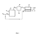
- Figure 1 is a schematic drawing of a flow scheme for a basic embodiment of the invention as it relates to a typical combustion process.
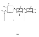
- FIG. 2 is a schematic drawing of a flow scheme for an embodiment of the invention as it in which a membrane separation step is used in the carbon dioxide capture step.
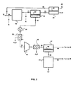
- Figure 3 is an embodiment of the invention as it relates to treatment of flue gas from a power plant or the like.
- Figure 4 is an alternative embodiment of the invention as it relates to treatment of flue gas from a power plant or the like.
- exhaust gas off-gas and emissions stream are used interchangeably herein.
- the invention is a process for controlling carbon dioxide emissions from combustion processes by membrane-based gas separation, and combustion processes including such gas separation.
- FIG. 1 A simple flow scheme for a basic embodiment of the invention is shown in Figure 1 .
- fuel stream 12, and air, oxygen-enriched air or oxygen stream 23 are introduced into a combustion step or zone, 11.
- Stream 23 is made up of sweep stream, 22, discussed below, and additional air or oxygen supply, stream 13.
- This stream usually contains at least carbon dioxide, water vapor and nitrogen, as well as the other components mentioned in the Summary section above.
- the stream is sent, at least in part, to carbon dioxide capture step, 15.
- This step may be carried out using any technology or combination of technologies that can create a concentrated carbon dioxide stream from the exhaust stream.
- the capture step yields a concentrated carbon dioxide product stream, 16, preferably containing greater than 60, 70, or 80 vol% carbon dioxide or more.
- This stream may be in the gas or liquid phase, and may comprise purified liquid carbon dioxide, for example.
- the concentrated stream may be sent for sequestration, or used or disposed of in any other appropriate way.
- the off-gas stream, 17, from the capture step still contains carbon dioxide, at a lower concentration than the raw exhaust stream. Typically, but not necessarily, this concentration is up to about 10 vol% carbon dioxide for coal-fired boilers, lower for gas-fired boilers.
- the off-gas stream is sent for treatment in membrane separation step or unit, 18.
- the unit contains membranes, 19, that are selectively permeable to carbon dioxide over nitrogen and to carbon dioxide over oxygen.
- the off-gas flows across the feed side of the membranes; a sweep gas of air, oxygen-enriched air or oxygen, stream 21, flows across the permeate side.
- the sweep stream picks up the preferentially permeating carbon dioxide, and the resulting permeate stream, 22, is withdrawn from the membrane unit and is combined with stream 13 to form the air or oxygen feed, 23, to the combustor.
- stream 13 may be omitted and the entirety of the oxygen-containing feed to the combustor may be provided by the sweep stream.
- the residue stream, 20 is reduced in carbon dioxide content to less than about 5 vol%, more preferably to less than 3 vol% and most preferably to less than 2 vol%. Typically, this stream is discharged to the environment
- the combustion step may be carried out in any way limited only in that it results in an off-gas, exhaust gas or flue gas containing carbon dioxide.
- Such combustion processes occur throughout industrialized society. Representative processes include those in which the combustion step is used to provide heat for an oven or furnace, such as a blast furnace. Other important processes are those in which the combustion step is used to generate steam to operate a turbine or other equipment to perform mechanical work or generate electric power. In yet other processes, the combustion gases themselves are used as a source of power to drive a turbine or the like, and may be treated before or after they have been used in the turbine.
- the fuel for the combustion step may be any fuel that can be combusted with oxygen, including, but not limited to, coal, coke, wood, biomass, solid wastes, oils and other natural and synthetic liquid fuels of all grades and types, and hydrocarbon-containing gas of any type, such as natural gas, landfill gas, coal mine gas or the like.
- the oxygen with which the fuel is combusted may be supplied in the form of high purity oxygen, oxygen-enriched air, normal air or any other suitable oxygen-containing mixture.
- the carbon capture step may be carried out using membrane or non-membrane technology, and may involve one or more than one type of separation procedure. In the event that membrane technology is used in whole or part for this step, the capture step remains a discrete unit operation separate from the subsequent membrane separation step, 18.
- Representative methods that may be used to capture carbon dioxide in this step include, but are not limited to, physical or chemical sorption, membrane separation, compression/low temperature condensation, adsorption, or any other known technology.
- Preferred technologies are absorption, such as amine scrubbing or chilled ammonia sorption, condensation, membrane separation, and combinations of these.
- Low-temperature or cryogenic condensation and absorption into an amine solution are the most common methods in current industrial use for capturing carbon dioxide and need no detailed description herein. Either method is well suited for use in the present invention.
- Methods of recovering liquid carbon dioxide by cryogenic condensation or distillation are well known in the art.
- a preferred process is the well known Ryan-Holmes process, in which a light hydrocarbon liquid or liquid mixture is added to the column to prevent formation of carbon dioxide solids or azeotropes in the column.
- Various specific techniques for carrying out low temperature condensation are taught, for example in U.S. Patents, 4,371,381 ; 4,923,493 ; 5,233,837 .
- the Ryan-Holmes process is taught in U.S. Patents 4,350,511 and 4,462,814 , for example.
- Methods of recovering carbon dioxide by absorption are also commonly used. In brief, these methods involve absorbing the carbon dioxide into a sorbent solution by physical or chemical interaction, then stripping the gas from the solution and recirculating the regenerated sorbent.
- sorbents may be used; most commonly the sorbent is amine-based and may include a single alkanolamine or a mix of amines.
- Other sorbents that may be used include chilled ammonia, as in the Alstom process, or other specialized proprietary solvents.
- the sorbent solution may be regenerated by steam stripping, and the carbon dioxide recovered from the stripping vapor by cooling and condensing the water.
- a representative process of this type that may be used is the Fluor Daniel Econamine FGTM process, which uses a monoethanolamine (MEA) based sorbent system. Very detailed descriptions of such processes can be found in the literature, for example in Gas Purification, A. Kohl and R. Nielsen (Fifth Edition, Gulf Publishing Co., Houston, Texas, 1997), pages 1188-1237 .
- membrane separation may be combined with cryogenic condensation, either upstream or downstream of the condensation step, for example, or gas released in the stripping step of the absorption process may be liquefied by condensation.
- cryogenic condensation either upstream or downstream of the condensation step, for example, or gas released in the stripping step of the absorption process may be liquefied by condensation.
- the third unit operation is membrane separation.
- the membrane separation step 18, as mentioned in the summary section, the membranes used in this step should exhibit high permeance for carbon dioxide, as well as high selectivity for carbon dioxide over nitrogen.
- Any membrane with suitable performance properties may be used.
- Many polymeric materials, especially elastomeric materials, are very permeable to carbon dioxide.
- Preferred membranes for separating carbon dioxide from nitrogen or other inert gases have a selective layer based on a polyether.
- a number of such membranes are known to have high carbon dioxide/nitrogen, such as 30, 40, 50 or above.
- a representative preferred material for the selective layer is Pebax®, a polyamide-polyether block copolymer material described in detail in U.S. Patent 4,963,165 .
- the membrane may take the form of a homogeneous film, an integral asymmetric membrane, a multilayer composite membrane, a membrane incorporating a gel or liquid layer or particulates, or any other form known in the art. If elastomeric membranes are used, the preferred form is a composite membrane including a microporous support layer for mechanical strength and a rubbery coating layer that is responsible for the separation properties.
- the membranes may be manufactured as flat sheets or as fibers and housed in any convenient module form, including spiral-wound modules, plate-and-frame modules and potted hollow-fiber modules.
- the making of all these types of membranes and modules is well known in the art.
- the modules preferably take the form of hollow-fiber modules, plate-and-frame modules or spiral-wound modules.
- Membrane step or unit 18 may contain a single membrane module or bank of membrane modules or an array of modules. A single unit or stage containing one or a bank of membrane modules is adequate for many applications. If the residue stream requires further purification, it may be passed to a second bank of membrane modules for a second processing step. If the permeate stream requires further concentration, it may be passed to a second bank of membrane modules for a second-stage treatment.
- Such multi-stage or multi-step processes, and variants thereof, will be familiar to those of skill in the art, who will appreciate that the membrane separation step may be configured in many possible ways, including single-stage, multistage, multistep, or more complicated arrays of two or more units in serial or cascade arrangements.
- the separation of components achieved by the membrane unit depends not only on the selectivity of the membrane for the components to be separated, but also on the pressure ratio.
- pressure ratio we mean the ratio of total feed pressure/total permeate pressure.
- the enrichment of a component that is, the ratio of component permeate partial pressure/component feed partial pressure
- the pressure ratio can never be greater than the pressure ratio. This relationship is true, irrespective of how high the selectivity of the membrane may be.
- the mathematical relationship between pressure ratio and selectivity predicts that whichever property is numerically smaller will dominate the separation.
- the separation achievable in the process will not be limited by the pressure ratio, but will depend on the selectivity capability of the membranes.
- the membrane selectivity is numerically very much higher than the pressure ratio, the pressure ratio will limit the separation. In this case, the permeate concentration becomes essentially independent of the membrane selectivity and is determined by the pressure ratio alone.
- High pressure ratios can be achieved by compressing the feed gas to a high pressure or by using vacuum pumps to create a lowered pressure on the permeate side, or a combination of both.
- the higher the selectivity the more costly in capital and energy it becomes to achieve a pressure ratio numerically comparable with or greater than the selectivity.
- the inventors have overcome this problem and made it possible to utilize more of the intrinsic selective capability of the membrane by diluting the permeate with the sweep gas, stream 21, thereby preventing the permeate side concentration building up to a limiting level.
- This mode of operation can be used with a pressure ratio of 1, that is, with no total pressure difference between the feed and permeate sides, with a pressure ratio less than 1, that is, with a higher total pressure on the permeate side than on the feed side, or with a relatively modest pressure ratio of less than 10 or less than 5, for example.
- the driving force for transmembrane permeation is supplied by lowering the partial pressure of the desired permeant on the permeate to a level below its partial pressure on the feed side.
- the use of the sweep gas stream 21 maintains a low carbon dioxide partial pressure on the permeate side, thereby providing driving force.
- the partial pressure on the permeate side may be controlled by adjusting the flow rate of the sweep stream to a desired value.
- the ratio of sweep gas flow to feed gas flow may be any value that provides the desired results, although the ratio sweep gas flow:feed gas flow will seldom be less than 0.1 or greater than 10.
- High ratios that is, high sweep flow rate
- Low ratios that is, low sweep flow rate
- the flow rate of the sweep stream should be between about 50% and 200% of the flow rate of the membrane feed stream, and most preferably between about 80% and 120%. Often a ratio of about 1:1 is convenient and appropriate.
- the total gas pressures on each side of the membrane may be the same or different, and each may be above or below atmospheric pressure. As mentioned above, if the pressures are about the same, the entire driving force is provided by the sweep mode operation.
- flue gas is available at atmospheric pressure, and the volumes of the streams involved are so large that it is not preferred to use either significant compression on the feed side or vacuum on the permeate side.
- slight compression such as from atmospheric to 2 or 3 bar, can be helpful and can provide part of a total carbon dioxide capture and recovery process that is relatively energy efficient, as shown in the examples below.
- fuel, stream 24, and air, oxygen-enriched air or oxygen stream 37 are introduced into a combustor, 25.
- Combustion off-gas stream, 26, is sent, at least in part, to the carbon capture step, in this case first membrane separation step or unit, 27.
- This unit contains membranes, 28, that are selectively permeable to carbon dioxide over nitrogen.
- This step may be pressure driven, by operating with a higher pressure on the feed side than on the permeate side. This may be achieved by compressing the feed, or more preferably, as the stream is smaller in volume, by pulling a partial vacuum on the permeate side, or by a combination of slight elevation of the feed pressure and slight vacuum on the permeate side.
- This step separates the off-gas stream into a carbon dioxide concentrated permeate stream, 29, and a carbon dioxide depleted residue stream, 30.
- the permeate stream will also typically be rich in water vapor, which may be easily condensed by cooling the stream.
- the permeate stream may then be sent to compression/low-temperature condensation or distillation to form a high purity carbon dioxide product.
- the driving force in the first membrane separation step may be augmented by using a steam sweep on the permeate side of the membrane.
- This can provide a significant improvement in the separation achieved in this step, as well as a reduction in energy consumption, since the steam used can be recovered from the permeate gas by simple condensation before the gas enters the vacuum pump.
- Residue stream, 30, is passed as feed to second membrane separation unit or step, 31, containing membranes, 32, that are selectively permeable to carbon dioxide over nitrogen and to carbon dioxide over oxygen.
- the residue stream flows across the feed side and a sweep gas of air, oxygen-enriched air or oxygen, stream 34, is introduced to the permeate side inlet of the membrane unit and flows across the permeate side, preferably in a flow pattern that is at least partly or substantially countercurrent to the flow pattern on the feed side.
- the ratio of the inlet flow rates of the feed and sweep streams is most preferably maintained at roughly 1:1, such that the sweep stream flow rate is between about 80% and 120% of the feed flow rate.
- the resulting permeate/sweep stream, 35 is withdrawn from the membrane unit and is combined with stream 36 to feed to the combustor.
- stream 36 may be omitted and the entirety of the oxygen-containing stream may be provided by the sweep stream.
- the residue stream, 33 is depleted in carbon dioxide and is discharged from the process.
- the off-gas from the combustor may contain 20% carbon dioxide and the residue vent gas may contain only 1 or 2% carbon dioxide.
- the carbon capture step is assumed to be made up of a membrane separation stage, which is similar in function to membrane separation step 27 in Figure 2 , plus a third membrane separation step and a carbon dioxide recovery step that yields a liquid or supercritical fluid purified carbon dioxide product.
- the third membrane separation step and the product recovery step may be carried out with the membrane separation step preceding the product recovery step or vice versa.
- flue gas stream, 41 emanates from the combustors of a power plant, 40, which is fed by stream 39, made up of fuel stream, 38, and air stream, 49.
- the pressure of this flue gas is just above atmospheric, such as 1.1 or 1.2 bar absolute.
- the flue gas pressure may be higher, such as 2-10 bar.
- the flue gas passes to the first section of the carbon capture step, specifically first membrane separation step, 42.
- the step is carried out using membranes, 43, having carbon dioxide permeance and selectivity characteristics as described above.
- This step separates the flue gas into a carbon dioxide depleted residue stream, 44, usually containing less than about 10% carbon dioxide, and a carbon dioxide enriched permeate stream, 50, usually containing at least about 40% carbon dioxide.
- the driving force for transmembrane permeation in this step is shown as being provided by a vacuum pump or train of vacuum pumps, 51, on the permeate side of the first membrane step.
- the vacuum pumps maintain a pressure down to about 0.1 bar, such as 0.5 bar or 0.2 bar on the permeate side.
- the pressure difference across the membrane generated by the vacuum pump(s) is small, so the membrane areas required to achieve the separation required are very large.
- the permeate gas stream passing through the vacuum pump has only a fraction of the volume of the flue gas, so the power used by the vacuum pump is smaller than the power that would be consumed by a compression train operating on the feed gas.
- Alternative preferred representative embodiments within the scope of the invention use modest compression of the feed stream, either alone or in conjunction with pulling a slight vacuum on the permeate side.
- An embodiment with slight feed compression is preferred, for example, in the case of a coal-fired power plant where the flue gas is at 1.1 bar absolute. This gas may be compressed to up to about 5 bar, such as 2 or 3 bar, and a portion of the energy used for the compressors may be recovered by expanding the final treated flue gas stream, 47, in a turbine before final discharge.
- the use of connected compressor/turbo-expander operations for energy recovery is well known in the art and in power plants in particular.
- the remaining permeate gas stream, 53 then passes through a compressor or compression train, 54, where it is compressed to a few bar pressure, such as 3 or 4 bar, and then through aftercooler, 55, where additional water is knocked out.
- the compressed gas forms the feed stream, 56, to the second membrane separation stage, 57, containing membranes, 58, having similar characteristics to those described previously.
- the permeate stream, 60, from this stage typically contains more than 80% carbon dioxide, and is sent to a cryogenic liquefaction plant, 61, to produce liquefied carbon dioxide product, 62.
- the off-gases, 63, from the liquefaction plant which are mostly nitrogen and oxygen, but which also may contain up to 10, 15 or 20% carbon dioxide, may be returned to the front of the flue gas treatment train at position A as shown, may be returned to the combustor at position B as shown, or may be recirculated, used or discharged in any other desired fashion.
- the residue stream, 59, from the second-stage membrane unit may be returned to the process at position A or B, or sent elsewhere as desired.
- the residue gas stream, 44, leaving the first membrane unit normally contains up to about 10% carbon dioxide.
- This gas passes as feed to the sweep-driven membrane separation step or unit, 45.
- This step uses membranes, 46, having similar characteristics to those described previously.
- the feed air, 48, to the power plant burner passes as a sweep gas on the other side of the membranes. Carbon dioxide permeate preferentially through the membranes and is returned with the feed air to the burner in permeate/sweep stream, 49.
- the treated flue gas stream, 47, is vented.
- Figure 4 a representative variant of the embodiment of Figure 3 is shown in Figure 4 , in which like elements are numbered as in Figure 3 .
- the process of Figure 3 differs from that of Figure 4 in that some compression, 73, is used to create a compressed feed stream, 74, at 2 or 3 bar, which forms the feed to membrane separation step, 42.
- FIG. 3 This design also differs from that of Figure 3 in the manner in which the compressed gas stream, 56, is processed.
- the stream passes to a membrane separation step, 57, and thence to the liquefaction plant.
- the membrane step is used instead to treat the off-gas from the liquefaction unit, so that the product recovery step precedes the last membrane separation step.
- stream 56 enters compression step or train, 64, where the pressure is raised to a suitable pressure for liquefaction, such as 20, 30, 40 bar or above, then passes as compressed stream, 65, to the condensation steps, 66.
- the gas is condensed/distilled at low temperature, typically by heat exchange against propylene or other low-temperature refrigerant, to produce carbon dioxide product stream, 67.
- the overhead stream, 68, from the carbon dioxide recovery column, is sent to membrane separation step, 69, containing membranes, 70, having similar characteristics to those described previously.
- the driving force for transmembrane permeation in this membrane unit is provided by the high pressure of the column overhead.
- the permeate stream, 72, is enriched in carbon dioxide and is recirculated at a suitable point to the compression train for the liquefaction steps, as indicated in the figure, or may be returned elsewhere in the process.
- the membrane residue stream, 71 may be returned to the combustor, to the flue gas treatment train before or after compression step 73, or may be used or discharged elsewhere as desired.
- the net energy used by the process is about 21 % of the 600 MW of power produced by the plant.
- the permeate gas contains about 40 mol% carbon dioxide.
- the total energy cost of the treatment train is about over 200 MW, or about one-third of the total output of the power plant.
- the process again achieves 90% carbon dioxide removal, from 174 to 17 MMscfd in the discharged flue gas, and cuts the concentration of carbon dioxide in the exhaust stream to 2 vol%.
- the membrane area requirement of 7.7 million m 2 is very large, but the energy requirement is low compared with Example 3, so that the process uses only 9% of the energy produced by the plant.
- the total energy requirement for carbon dioxide capture is reduced to 93 MW, about 15% of the total energy output of the plant.
- Example 4 A calculation similar to that of Example 4 was performed to illustrate the treatment of the flue gas from a coal-fired power plant by membrane separation, according to the embodiment of Figure 4 .
- a vacuum pump, 51 is used in the permeate line, 50, of the first membrane step, 42.
- This cross flow membrane unit only removes a portion of the CO2 in flue gas in a single pass, to reduce the membrane area and energy required in this step.
- the residue gas, 44, leaving the cross flow membrane step still contains 7.4% carbon dioxide.
- This gas in further treated in second membrane step, 45, which has a countercurrent/sweep configuration.
- Feed air, 48, to the boiler passes on the permeate side of this membrane unit as a sweep stream.
- the permeate gas leaving the second pump section, 54 is sent to a compression-condensation-membrane loop for liquefaction.
- Stream 71 was assumed to be recirculated to join flue gas stream 41.
- the process uses 12% of generated power to separate carbon dioxide from flue gas, with an additional 4-7% required for carbon dioxide compression-condensation-membrane separation in the liquefaction loop.
- the total energy usage is thus about 16-19% of the total power output of the power plant.
Claims (15)
- Procédé pour commander les émissions de dioxyde de carbone de processus de combustion, comprenant :(a) exécuter un processus de combustion par la combustion d'un mélange d'un combustible (12) et de l'air, air enrichi en oxygène ou oxygène (23), en créant ainsi un flux d'échappement (14) comprenant du dioxyde de carbone et de l'azote ;(b) exécuter une étape de capture de dioxyde de carbone (15) pour retirer une portion du dioxyde de carbone sous forme concentrée (16) du flux d'échappement (14), en créant ainsi un flux de gaz de carneau (17) de l'étape de capture qui est moins concentré en dioxyde de carbone que dans le flux d'échappement (14) ;(c) réaliser une membrane (19) ayant un côté d'amenée et un côté de perméat, et perméable sélectivement au dioxyde de carbone sur l'azote et au dioxyde de carbone sur l'oxygène ;(d) faire passer au moins une portion du flux de gaz de carneau (17) sur le côté d'amenée ;(e) faire passer un flux de balayage (21) sur le côté de perméat ;(f) retirer du côté d'amenée un flux d'évent appauvri en dioxyde de carbone (20) ;(g) retirer du côté de perméat un flux de perméat (22) comprenant de l'oxygène et du dioxyde de carbone ;(h) faire passer le flux de perméat (22) à l'étape (a) comme au moins une partie de l'air, de l'air enrichi en oxygène et de l'oxygène utilisé à l'étape (a),caractérisé en ce que le flux de balayage (21) est de l'air, de l'air enrichi en oxygène ou de l'oxygène.
- Procédé selon la revendication 1, dans lequel le flux d'échappement (14) comprend du gaz de carneau d'une centrale électrique fonctionnant au charbon ou au gaz.
- Procédé selon la revendication 1, dans lequel l'étape de capture du dioxyde de carbone comprend au moins un processus sélectionné dans le groupe consistant en absorption, adsorption, liquéfaction et séparation membranaire.
- Procédé selon la revendication 1, dans lequel l'étape de capture du dioxyde de carbone (15) comprend la séparation membranaire.
- Procédé selon la revendication 1, dans lequel la membrane (19) possède une perméabilité au dioxyde de carbone d'au moins 500 gpu sous des conditions de fonctionnement du processus.
- Procédé selon la revendication 1, dans lequel le flux d'évent (20) contient moins que 5% en vol. de dioxyde de carbone.
- Procédé selon la revendication 1, dans lequel le flux des gaz de carneau (17) est compressé à une pression jusqu'à environ 5 bar avec qu'il ne passe au côté d'amenée.
- Procédé selon la revendication 1, dans lequel l'étape de capture (15) du dioxyde de carbone comprend :(i) réaliser une première membrane (28) ayant un premier côté d'amenée et un premier côté de perméat, et étant sélective pour le dioxyde de carbone sur l'azote ;(ii) maintenir une force d'entraînement pour la perméation transmembranaire ;(iii) faire passer au moins une portion du flux d'échappement (14) sur le premier côté d'amenée ;(iv) retirer du premier côté d'amenée un premier flux résiduel (30) appauvri en dioxyde de carbone comparé avec le flux d'échappement (14) ; et(v) retirer du premier côté de perméat un premier flux de perméat (29) comprenant du dioxyde de carbone, etoù le premier flux résiduel (30) est le flux de gaz de carneau (17).
- Procédé selon la revendication 8, comprenant en outre le passage du premier flux de perméat (29) à une étape de liquéfaction de dioxyde de carbone.
- Procédé selon la revendication 8, dans lequel la force d'entraînement pour la perméation transmembranaire est réalisée au moins en partie en maintenant le premier côté de perméat sous un vide partiel au moyen d'une pompe de vide par laquelle le premier flux de perméat (29) est retiré à l'étape (f).
- Procédé selon la revendication 10, dans lequel la force d'entraînement pour la perméation transmembranaire est réalisée au moins en partie en balayant le premier côté de perméat avec de la vapeur.
- Procédé selon la revendication 1, pour retirer le dioxyde de carbone d'un flux de gaz de carneau (41) d'une centrale électrique :où le flux de gaz de carneau (41) de la centrale électrique est le flux d'échappement (14) comprenant du dioxyde de carbone et de l'azote ;où l'étape de capture de carbone (15) comprend :(A) exécuter une première étape de séparation membranaire en :(i) réaliser une première unité membranaire contenant une première membrane (43) ayant un premier côté d'amenée et un premier côté de perméat ;(ii) réaliser une première force d'entraînement pour la perméation transmembranaire en maintenant le premier côté de perméat sous un vide partiel ;(iii) faire passer le flux de gaz de carneau (41) sur le côté d'amenée ;(iv) retirer du premier côté d'amenée un premier flux de résidu (44) appauvri en dioxyde de carbone ;(v) retirer du premier côté de perméat un premier flux de perméat (50) enrichi en dioxyde de carbone ;(B) compresser le premier flux de perméat (50) ;(C) refroidir le premier flux de perméat (50) en condensant ainsi l'eau pour obtenir un premier flux de perméat compressé, refroidi ;(D) exécuter une combinaison d'une deuxième étape de séparation membranaire et d'une étape de liquéfaction pour former un produit de dioxyde de carbone liquide (62) ; etoù le premier flux résiduel appauvri en dioxyde de carbone (44) est le flux des gaz de carneau (17), etoù le flux de perméat (22) est utilisé comme flux d'amenée d'air pour un organe de combustion dans la centrale électrique.
- Procédé selon la revendication 12, dans lequel l'étape de liquéfaction précède la deuxième étape de séparation membranaire de sorte qu'un flux supérieur de l'étape de liquéfaction est traité par la deuxième étape de séparation membranaire.
- Procédé selon la revendication 12, dans lequel la deuxième étape de séparation membranaire précède l'étape de liquéfaction de sorte qu'un deuxième flux de perméat de la deuxième étape de séparation membranaire est envoyé à l'étape de liquéfaction.
- Procédé selon la revendication 12, dans lequel le flux de gaz de carneau traité contient moins que 5% en vol. de dioxyde de carbone.
Priority Applications (1)
| Application Number | Priority Date | Filing Date | Title |
|---|---|---|---|
| PL09746924T PL2296784T3 (pl) | 2008-05-12 | 2009-05-08 | Sposób rozdziału gazów przy użyciu membran ze zmiataniem permeatu w celu usunięcia CO<sub>2 </sub>z gazów spalinowych |
Applications Claiming Priority (2)
| Application Number | Priority Date | Filing Date | Title |
|---|---|---|---|
| US12741508P | 2008-05-12 | 2008-05-12 | |
| PCT/US2009/002874 WO2009139835A1 (fr) | 2008-05-12 | 2009-05-08 | Procédé de séparation de gaz à l'aide de membranes avec un balayage du perméat pour enlever le co<sb>2</sb> à partir de gaz de combustion |
Publications (2)
| Publication Number | Publication Date |
|---|---|
| EP2296784A1 EP2296784A1 (fr) | 2011-03-23 |
| EP2296784B1 true EP2296784B1 (fr) | 2013-09-04 |
Family
ID=40933110
Family Applications (1)
| Application Number | Title | Priority Date | Filing Date |
|---|---|---|---|
| EP09746924.1A Active EP2296784B1 (fr) | 2008-05-12 | 2009-05-08 | Procédé de séparation de gaz à l'aide de membranes avec un balayage du perméat pour enlever le co2 à partir de gaz de combustion |
Country Status (6)
| Country | Link |
|---|---|
| US (4) | US7964020B2 (fr) |
| EP (1) | EP2296784B1 (fr) |
| CN (1) | CN102026702B (fr) |
| PL (1) | PL2296784T3 (fr) |
| RU (1) | RU2489197C2 (fr) |
| WO (1) | WO2009139835A1 (fr) |
Cited By (1)
| Publication number | Priority date | Publication date | Assignee | Title |
|---|---|---|---|---|
| US11471823B2 (en) | 2019-02-12 | 2022-10-18 | Haffmans B.V. | System and method for separating a gas mixture |
Families Citing this family (93)
| Publication number | Priority date | Publication date | Assignee | Title |
|---|---|---|---|---|
| WO2009139835A1 (fr) | 2008-05-12 | 2009-11-19 | Membrane Technology And Research, Inc. | Procédé de séparation de gaz à l'aide de membranes avec un balayage du perméat pour enlever le co<sb>2</sb> à partir de gaz de combustion |
| US8034168B2 (en) | 2008-05-12 | 2011-10-11 | Membrane Technology & Research, Inc | Combustion systems and power plants incorporating parallel carbon dioxide capture and sweep-based membrane separation units to remove carbon dioxide from combustion gases |
| US8568510B2 (en) * | 2008-05-12 | 2013-10-29 | Membrane Technology And Research, Inc | Gas-separation processes using membranes with permeate sweep to recover reaction feedstocks |
| US8273152B2 (en) * | 2008-11-14 | 2012-09-25 | Praxair Technology, Inc. | Separation method and apparatus |
| US8114191B2 (en) * | 2008-12-11 | 2012-02-14 | General Electric Company | Energy efficient approach to CO2 capture process |
| EP2210656A1 (fr) * | 2009-01-27 | 2010-07-28 | General Electric Company | Procédé et système de séparation de dioxyde de carbone hybride |
| US20100232985A1 (en) * | 2009-03-10 | 2010-09-16 | Generon Igs, Inc. | Fuel gas conditioning with membrane separation |
| US8137435B2 (en) * | 2009-03-31 | 2012-03-20 | L'air Liquide Societe Anonyme Pour L'etude Et L'exploitation Des Procedes Georges Claude | Carbon dioxide recovery from low concentration sources |
| DE102009016015A1 (de) * | 2009-04-02 | 2010-10-07 | Forschungszentrum Jülich GmbH | Vorrichtung und Verfahren zur Entfernung von Kohlendioxid (CO2) aus dem Rauchgas einer Feuerungsanlage nach der Energieumwandlung |
| US20100275777A1 (en) * | 2009-04-30 | 2010-11-04 | Hasse David J | Membrane-Based Process for CO2 Capture from Flue Gases Generated by Oxy-Combustion of Coal |
| US20100300114A1 (en) * | 2009-05-29 | 2010-12-02 | General Electric Company | Membrane separation |
| US8617292B2 (en) * | 2009-12-15 | 2013-12-31 | L'Air Liquide, Société Anonyme pour l'Etude et l'Exploitation des Procédés Georges Claude | Method of obtaining carbon dioxide from carbon dioxide-containing gas mixture |
| US8734569B2 (en) * | 2009-12-15 | 2014-05-27 | L'air Liquide, Societe Anonyme Pour L'etude Et L'exploitation Des Procedes Georges Claude | Method of obtaining carbon dioxide from carbon dioxide-containing gas mixture |
| US8663364B2 (en) * | 2009-12-15 | 2014-03-04 | L'Air Liquide, Société Anonyme pour l'Étude et l'Éxploitation des Procédés Georges Claude | Method of obtaining carbon dioxide from carbon dioxide-containing gas mixture |
| US8435326B2 (en) * | 2010-01-15 | 2013-05-07 | G.D.O. | Multi-stage process for removing CO2 relative to hydrogen from syngas streams |
| US8454724B2 (en) | 2010-06-30 | 2013-06-04 | Uop Llc | Flexible system to remove carbon dioxide from a feed natural gas |
| ES2624775T3 (es) * | 2010-07-01 | 2017-07-17 | Evonik Fibres Gmbh | Procedimiento para la separación de gases |
| US9140186B2 (en) * | 2010-09-13 | 2015-09-22 | Membrane Technology And Research, Inc | Sweep-based membrane gas separation integrated with gas-fired power production and CO2 recovery |
| US9856769B2 (en) | 2010-09-13 | 2018-01-02 | Membrane Technology And Research, Inc. | Gas separation process using membranes with permeate sweep to remove CO2 from combustion exhaust |
| CN103249466B (zh) * | 2010-09-13 | 2016-09-14 | 膜技术研究股份有限公司 | 使用基于吹扫的膜分离和吸收步骤从烟气分离二氧化碳的工艺 |
| US9005335B2 (en) * | 2010-09-13 | 2015-04-14 | Membrane Technology And Research, Inc. | Hybrid parallel / serial process for carbon dioxide capture from combustion exhaust gas using a sweep-based membrane separation step |
| US8220247B2 (en) * | 2010-09-13 | 2012-07-17 | Membrane Technology And Research, Inc. | Power generation process with partial recycle of carbon dioxide |
| US8220248B2 (en) * | 2010-09-13 | 2012-07-17 | Membrane Technology And Research, Inc | Power generation process with partial recycle of carbon dioxide |
| PL2616163T3 (pl) * | 2010-09-13 | 2018-01-31 | Membrane Tech And Research Inc | Sposób rozdziału gazów na membranach stosującego zmiatanie permeatu do usuwania CO2 ze spalin z paliwa gazowego |
| US9457313B2 (en) | 2010-09-13 | 2016-10-04 | Membrane Technology And Research, Inc. | Membrane technology for use in a power generation process |
| WO2012036650A1 (fr) * | 2010-09-13 | 2012-03-22 | Membrane Technology And Research, Inc. | Procédé à boucle à membrane pour la séparation de dioxyde de carbone en vue d'une utilisation sous forme gazeuse à partir de gaz de combustion |
| US20120102964A1 (en) * | 2010-10-29 | 2012-05-03 | General Electric Company | Turbomachine including a carbon dioxide (co2) concentration control system and method |
| EP2457637B8 (fr) * | 2010-11-24 | 2016-09-21 | General Electric Technology GmbH | Système de chaudière et procédé de nettoyage de gaz combustible riche en dioxyde de carbone et système de chaudière |
| KR101275685B1 (ko) * | 2011-04-22 | 2013-06-14 | 한국에너지기술연구원 | 분리막을 이용한 연소배가스 처리시스템 |
| US8168685B2 (en) | 2011-07-01 | 2012-05-01 | Membrane Technology And Research, Inc | Process for the production of methanol including one or more membrane separation steps |
| AU2012278892B2 (en) | 2011-07-02 | 2017-10-26 | Inventys Thermal Technologies Inc. | System and method for integrated adsorptive gas separation of combustion gases |
| EP2559658A1 (fr) * | 2011-08-19 | 2013-02-20 | Huntsman International LLC | Procédé de séparation de chlorure de carbonyle et de chlorure d'hydrogène d'un flux fluide comportant du chlorure de carbonyle et du chlorure d'hydrogène |
| EP3338876B1 (fr) * | 2011-12-27 | 2020-07-01 | Evonik Fibres GmbH | Procédé de séparation de gaz par des membranes |
| US8829059B2 (en) * | 2012-06-27 | 2014-09-09 | Membrane Technology And Research, Inc. | Processes for the production of methanol using sweep-based membrane separation steps |
| US9103549B2 (en) * | 2012-08-23 | 2015-08-11 | The Boeing Company | Dual stream system and method for producing carbon dioxide |
| US20140141139A1 (en) * | 2012-11-19 | 2014-05-22 | Membrane Technology And Research, Inc. | Membrane Separation Process for Controlling Gas Concentrations Within Produce Shipping or Storage Containers |
| WO2014078899A1 (fr) * | 2012-11-22 | 2014-05-30 | Commonwealth Scientific And Industrial Research Organisation | Procédé et appareil pour une régénération de liquide absorbant à intégration de chaleur faisant appel à une désorption gazeuse |
| US10174943B2 (en) | 2012-12-31 | 2019-01-08 | Inventys Thermal Technologies Inc. | System and method for integrated carbon dioxide gas separation from combustion gases |
| US20140272614A1 (en) * | 2013-03-15 | 2014-09-18 | Exxonmobil Research And Engineering Company | Integrated power generation and carbon capture using fuel cells |
| US9077008B2 (en) | 2013-03-15 | 2015-07-07 | Exxonmobil Research And Engineering Company | Integrated power generation and chemical production using fuel cells |
| SG11201506730WA (en) | 2013-03-15 | 2015-09-29 | Exxonmobil Res & Eng Co | Integrated power generation using molten carbonate fuel cells |
| TWI495510B (zh) * | 2013-10-29 | 2015-08-11 | Atomic Energy Council | Fibrous membrane reaction device |
| CN103816726B (zh) * | 2014-02-13 | 2015-12-02 | 上海穗杉实业有限公司 | 一种祛除空气中颗粒类污染物的方法与装置 |
| RU2553748C1 (ru) * | 2014-03-05 | 2015-06-20 | Игорь Викторович Кузнецов | Способ сжигания топлива |
| CN104941394B (zh) | 2014-03-31 | 2020-03-03 | 宇部兴产株式会社 | 气体分离系统及富化气体的制造方法 |
| RU2571636C1 (ru) * | 2014-05-23 | 2015-12-20 | Общество с ограниченной ответственностью "Краснодарский Компрессорный Завод" | Способ газоразделения и газоразделительное устройство |
| RU2687951C2 (ru) * | 2014-08-07 | 2019-05-16 | Линде Акциенгезелльшафт | Извлечение газов, в частности неконденсирующихся газов, из массовых потоков, в частности из потоков отходящих газов с процессов полимеризации |
| US9783467B2 (en) * | 2014-09-15 | 2017-10-10 | Membrane Technology And Research, Inc. | Process for recovering olefins from manufacturing operations |
| US10186724B2 (en) | 2015-02-04 | 2019-01-22 | Bloom Energy Corporation | Carbon dioxide separator, fuel cell system including same, and method of operating the fuel cell system |
| US10173178B1 (en) | 2015-04-27 | 2019-01-08 | Bloom Energy Corporation | Carbon dioxide separator membrane structure, method of manufacturing same, and carbon dioxide separator including same |
| US10105638B2 (en) | 2015-05-29 | 2018-10-23 | Korea Institute Of Energy Research | Apparatus for separating CO2 from combustion gas using multi-stage membranes |
| KR101678502B1 (ko) | 2015-05-29 | 2016-11-23 | 한국에너지기술연구원 | 다단 분리막을 이용하여 연소가스로부터 이산화탄소를 분리하는 장치 |
| KR101742087B1 (ko) | 2015-05-29 | 2017-06-02 | 한국에너지기술연구원 | 연소가스로부터 이산화탄소를 자가 회수 방식으로 분리하는 장치 |
| US11358093B2 (en) | 2015-05-29 | 2022-06-14 | Ohio State Innovation Foundation | Methods for the separation of CO2 from a gas stream |
| DE102015213252A1 (de) * | 2015-07-15 | 2017-01-19 | Wacker Chemie Ag | Kontinuierliches Verfahren zur Reinigung von bei der Produktion von Siliconen anfallender Prozessabluft |
| US9889401B2 (en) | 2015-12-18 | 2018-02-13 | General Electric Company | Flow management and CO2-recovery apparatus and method of use |
| US11473838B2 (en) | 2015-12-18 | 2022-10-18 | Baker Hughes Holdings Llc | Flow management and CO2-recovery apparatus and method of use |
| CN105879594B (zh) * | 2016-05-26 | 2018-11-20 | 天邦膜技术国家工程研究中心有限责任公司 | 一种没有氦气损失的含氦水溶气脱湿方法 |
| US10539324B2 (en) * | 2016-06-09 | 2020-01-21 | King Fahd University Of Petroleum And Minerals | System for combusting a methane stream and a method of combustion |
| US9546785B1 (en) * | 2016-06-13 | 2017-01-17 | Membrane Technology And Research, Inc. | Sweep-based membrane separation process for removing carbon dioxide from exhaust gases generated by multiple combustion sources |
| US9782718B1 (en) * | 2016-11-16 | 2017-10-10 | Membrane Technology And Research, Inc. | Integrated gas separation-turbine CO2 capture processes |
| US10239015B2 (en) * | 2016-11-22 | 2019-03-26 | Korea Institute Of Energy Research | Apparatus and method for separating carbon dioxide with self recycle loop |
| EP3554674A1 (fr) | 2016-12-14 | 2019-10-23 | Membrane Technology and Research, Inc. | Séparation et co-capture du co2 et so2 contenus dans les gaz de combustion de processus de combustion |
| CN108339377B (zh) * | 2017-01-23 | 2021-02-26 | 神华集团有限责任公司 | 一种从含co2气流中分离co2的方法和膜分离系统 |
| US10561978B2 (en) | 2017-08-09 | 2020-02-18 | Generon Igs, Inc. | Membrane-based gas separation with retentate sweep |
| US10874980B2 (en) * | 2017-08-09 | 2020-12-29 | Hamilton Sundstrand Corporation | Inert gas generating system |
| DE102017215950A1 (de) * | 2017-09-11 | 2019-03-14 | Robert Bosch Gmbh | Verbindungsstück für Fluidleitungen eines Abgasnachbehandlungssystems |
| US11229871B2 (en) * | 2017-10-09 | 2022-01-25 | The Texas A&M University System | Integrated carbon capture and conversion for production of syngas |
| RU2670171C1 (ru) * | 2017-10-27 | 2018-10-19 | Александр Игоревич Костин | Установка и способ получения жидкого диоксида углерода из газовых смесей, содержащих диоксид углерода, с использованием мембранной технологии |
| KR20190107515A (ko) | 2018-03-12 | 2019-09-20 | 한국에너지기술연구원 | 이산화탄소 포집 효율이 향상된 이산화탄소 분리 시스템과 분리 방법 및 분리막 장치 |
| US11117092B2 (en) | 2018-03-14 | 2021-09-14 | Gas Technology Institute | Energy efficient membrane-based process for CO2 capture |
| US11471825B2 (en) * | 2018-03-14 | 2022-10-18 | Gas Technology Institute | Membrane absorption process for CO2 capture |
| KR20190114492A (ko) | 2018-03-30 | 2019-10-10 | 한국에너지기술연구원 | 고농도 이산화탄소 포집을 위한 저온 막분리 장치와 방법 및 이를 이용한 이산화탄소 포집 시스템 |
| US11772052B2 (en) | 2018-09-14 | 2023-10-03 | Ohio State Innovation Foundation | Membranes for gas separation |
| KR20210094074A (ko) | 2018-11-30 | 2021-07-28 | 퓨얼 셀 에너지, 인크 | Co2 이용률이 향상된 용융 탄산염 연료 전지의 증가된 압력 작동 |
| WO2020112770A1 (fr) | 2018-11-30 | 2020-06-04 | Exxonmobil Research And Engineering Company | Régénération de piles à combustible à carbonate fondu destinée à la capture profonde de co2 |
| US11888187B2 (en) | 2018-11-30 | 2024-01-30 | ExxonMobil Technology and Engineering Company | Operation of molten carbonate fuel cells with enhanced CO2 utilization |
| WO2020112834A1 (fr) | 2018-11-30 | 2020-06-04 | Exxonmobil Research And Engineering Company | Étagement de pile à combustible pour piles à combustible à carbonate fondu |
| JP7258144B2 (ja) | 2018-11-30 | 2023-04-14 | フュエルセル エナジー, インコーポレイテッド | Co2利用率を向上させて動作させる燃料電池のための改質触媒パターン |
| WO2020112806A1 (fr) | 2018-11-30 | 2020-06-04 | Exxonmobil Research And Engineering Company | Cathode en couches pour pile à combustible à carbonate fondu |
| RU2746005C2 (ru) * | 2019-08-19 | 2021-04-05 | Алексей Леонидович Западинский | Комплекс для добычи углеводородов |
| RU2746004C2 (ru) * | 2019-08-19 | 2021-04-05 | Алексей Леонидович Западинский | Способ добычи углеводородов |
| US11148097B2 (en) | 2019-09-03 | 2021-10-19 | Korea Institute Of Energy Research | Low-temperature membrane separation device and method for capturing carbon dioxide at high concentration |
| EP4066301A1 (fr) | 2019-11-26 | 2022-10-05 | ExxonMobil Technology and Engineering Company | Fonctionnement de piles à combustible à carbonate fondu présentant un niveau de remplissage d'électrolyte élevé |
| KR20220113681A (ko) | 2019-11-26 | 2022-08-16 | 엑손모빌 테크놀로지 앤드 엔지니어링 컴퍼니 | 연료 전지 모듈 조립체 및 이를 사용하는 시스템 |
| KR102154167B1 (ko) | 2020-01-30 | 2020-09-09 | 한국에너지기술연구원 | 이산화탄소 포집 효율이 향상된 이산화탄소 분리 시스템과 분리 방법 및 분리막 장치 |
| KR20200015664A (ko) | 2020-02-03 | 2020-02-12 | 한국에너지기술연구원 | 고농도 이산화탄소 포집을 위한 저온 막분리 장치와 방법 및 이를 이용한 이산화탄소 포집 시스템 |
| US11813566B2 (en) | 2020-05-15 | 2023-11-14 | Membrane Technology And Research, Inc. | Membrane CO2 separation process |
| US20220205717A1 (en) * | 2020-12-31 | 2022-06-30 | Saudi Arabian Oil Company | Recovery of noncondensable gas components from a gaseous mixture |
| JP2024503110A (ja) | 2021-01-15 | 2024-01-24 | セエルイ フルタフェラク | メタノール合成反応器 |
| CN114367174A (zh) * | 2022-01-25 | 2022-04-19 | 北京丰润铭科贸有限责任公司 | 一种膜分离去除二氧化碳成分的电厂烟气净化系统 |
| WO2023191794A1 (fr) * | 2022-03-31 | 2023-10-05 | Membrane Technology And Research, Inc. | Procédés de membrane de réduction de puissance |
| CN114917736A (zh) * | 2022-06-10 | 2022-08-19 | 重庆远达烟气治理特许经营有限公司科技分公司 | 用于处理含有二氧化碳的烟气的系统和方法及发电系统 |
Family Cites Families (51)
| Publication number | Priority date | Publication date | Assignee | Title |
|---|---|---|---|---|
| US550036A (en) * | 1895-11-19 | Lee anderson | ||
| US990169A (en) * | 1902-06-17 | 1911-04-18 | Underwood Typewriter Co | Type-writing machine. |
| US4235983A (en) * | 1978-10-04 | 1980-11-25 | Standard Oil Company (Indiana) | Purification of olefin recycle to polymerization |
| US4462814A (en) * | 1979-11-14 | 1984-07-31 | Koch Process Systems, Inc. | Distillative separations of gas mixtures containing methane, carbon dioxide and other components |
| GB2069118B (en) * | 1980-02-13 | 1984-10-03 | Cryoplants Ltd | Method for purifying a gas mixture |
| US4350511A (en) * | 1980-03-18 | 1982-09-21 | Koch Process Systems, Inc. | Distillative separation of carbon dioxide from light hydrocarbons |
| GB8508002D0 (en) * | 1985-03-27 | 1985-05-01 | Costain Petrocarbon | Recovering carbon dioxide |
| US4639257A (en) * | 1983-12-16 | 1987-01-27 | Costain Petrocarbon Limited | Recovery of carbon dioxide from gas mixture |
| US4518399A (en) * | 1984-08-24 | 1985-05-21 | Monsanto Company | Process for recovering gases from landfills |
| US4602477A (en) * | 1985-06-05 | 1986-07-29 | Air Products And Chemicals, Inc. | Membrane-aided distillation for carbon dioxide and hydrocarbon separation |
| US4659343A (en) * | 1985-09-09 | 1987-04-21 | The Cynara Company | Process for separating CO2 from other gases |
| US4824443A (en) * | 1986-12-30 | 1989-04-25 | Bend Research, Inc. | Gas separation by composite solvent-swollen membranes |
| US4755192A (en) * | 1987-04-15 | 1988-07-05 | Board Of Regents, The University Of Texas System | Processes to condition gas permeable membranes |
| US4963165A (en) * | 1987-04-27 | 1990-10-16 | Membrane Technology & Research, Inc. | Composite membrane, method of preparation and use |
| US4783203A (en) * | 1987-10-22 | 1988-11-08 | Union Carbide Corporation | Integrated pressure swing adsorption/membrane separation process |
| US4923493A (en) * | 1988-08-19 | 1990-05-08 | Exxon Production Research Company | Method and apparatus for cryogenic separation of carbon dioxide and other acid gases from methane |
| US4931070A (en) * | 1989-05-12 | 1990-06-05 | Union Carbide Corporation | Process and system for the production of dry, high purity nitrogen |
| US4990168A (en) * | 1989-07-17 | 1991-02-05 | Sauer Richard A | Recovery of carbon dioxide from a carbon dioxide plant vent gas using membranes |
| US5354547A (en) * | 1989-11-14 | 1994-10-11 | Air Products And Chemicals, Inc. | Hydrogen recovery by adsorbent membranes |
| US5034126A (en) * | 1990-01-29 | 1991-07-23 | The Dow Chemical Company | Counter current dual-flow spiral wound dual-pipe membrane separation |
| US5067971A (en) * | 1990-02-12 | 1991-11-26 | Union Carbide Industrial Gases Technology Corporation | Process for dehydration of gases and composite permeable membranes therefor |
| BR9100570A (pt) * | 1990-02-12 | 1991-10-29 | Union Carbide Ind Gases Tech | Processo para a desidratacao de gases e membranas composito para o mesmo |
| US5240471A (en) | 1991-07-02 | 1993-08-31 | L'air Liquide | Multistage cascade-sweep process for membrane gas separation |
| US5233837A (en) * | 1992-09-03 | 1993-08-10 | Enerfex, Inc. | Process and apparatus for producing liquid carbon dioxide |
| US5332424A (en) * | 1993-07-28 | 1994-07-26 | Air Products And Chemicals, Inc. | Hydrocarbon fractionation by adsorbent membranes |
| US5455016A (en) * | 1994-08-31 | 1995-10-03 | Air Products And Chemicals, Inc. | Membrane-assisted process to produce ammonia |
| US5681433A (en) * | 1994-09-14 | 1997-10-28 | Bend Research, Inc. | Membrane dehydration of vaporous feeds by countercurrent condensable sweep |
| US5500036A (en) | 1994-10-17 | 1996-03-19 | Air Products And Chemicals, Inc. | Production of enriched oxygen gas stream utilizing hollow fiber membranes |
| US5641337A (en) | 1995-12-08 | 1997-06-24 | Permea, Inc. | Process for the dehydration of a gas |
| NO302454B1 (no) * | 1996-07-31 | 1998-03-09 | Kvaerner Asa | Fremgangsmåte til fjerning av karbondioksid fra gasser |
| IL121538A (en) | 1996-08-14 | 1999-12-31 | Bend Res Inc | Process for the removal of vapor |
| US5753010A (en) * | 1996-10-28 | 1998-05-19 | Air Products And Chemicals, Inc. | Hydrogen recovery by pressure swing adsorption integrated with adsorbent membranes |
| US6077323A (en) * | 1997-06-06 | 2000-06-20 | Air Products And Chemicals, Inc. | Synthesis gas production by ion transport membranes |
| NO308398B1 (no) * | 1997-06-06 | 2000-09-11 | Norsk Hydro As | Fremgangsmate for utforelse av katalytiske eller ikke-katalytiske prosesser hvori oksygen er ±n av reaktantene |
| US6406519B1 (en) * | 1998-03-27 | 2002-06-18 | Advanced Technology Materials, Inc. | Gas cabinet assembly comprising sorbent-based gas storage and delivery system |
| US6085549A (en) * | 1998-04-08 | 2000-07-11 | Messer Griesheim Industries, Inc. | Membrane process for producing carbon dioxide |
| US6114400A (en) * | 1998-09-21 | 2000-09-05 | Air Products And Chemicals, Inc. | Synthesis gas production by mixed conducting membranes with integrated conversion into liquid products |
| US6478852B1 (en) * | 2000-02-18 | 2002-11-12 | Cms Technology Holdings, Inc. | Method of producing nitrogen enriched air |
| US6592650B2 (en) * | 2000-05-19 | 2003-07-15 | Membrane Technology And Research, Inc. | Gas separation using organic-vapor-resistant membranes and PSA |
| US6695983B2 (en) * | 2001-04-24 | 2004-02-24 | Praxair Technology, Inc. | Syngas production method utilizing an oxygen transport membrane |
| GB0228074D0 (en) * | 2002-12-02 | 2003-01-08 | Molecular Products Ltd | Carbon dioxide absorption |
| US6648944B1 (en) * | 2003-01-28 | 2003-11-18 | Membrane Technology And Research, Inc. | Carbon dioxide removal process |
| DE602006019543D1 (de) * | 2006-02-06 | 2011-02-24 | Samsung Sdi Germany Gmbh | Kohlendioxidabscheider für Direkt-Methanol-Brennstoffzellensystem |
| US7763097B2 (en) * | 2006-06-08 | 2010-07-27 | University of Pittsburgh—of the Commonwealth System of Higher Education | Devices, systems and methods for reducing the concentration of a chemical entity in fluids |
| US20080011161A1 (en) * | 2006-07-17 | 2008-01-17 | General Electric Company | Carbon dioxide capture systems and methods |
| US20080127632A1 (en) * | 2006-11-30 | 2008-06-05 | General Electric Company | Carbon dioxide capture systems and methods |
| US8088196B2 (en) * | 2007-01-23 | 2012-01-03 | Air Products And Chemicals, Inc. | Purification of carbon dioxide |
| MX339437B (es) * | 2008-02-19 | 2016-05-26 | Global Res Technologies Llc | Extraccion y formacion de complejos del dioxido de carbono. |
| US8591627B2 (en) * | 2009-04-07 | 2013-11-26 | Innosepra Llc | Carbon dioxide recovery |
| WO2009139835A1 (fr) | 2008-05-12 | 2009-11-19 | Membrane Technology And Research, Inc. | Procédé de séparation de gaz à l'aide de membranes avec un balayage du perméat pour enlever le co<sb>2</sb> à partir de gaz de combustion |
| US7901646B2 (en) * | 2009-08-05 | 2011-03-08 | General Electric Company | System and method for sulfur recovery |
-
2009
- 2009-05-08 WO PCT/US2009/002874 patent/WO2009139835A1/fr active Application Filing
- 2009-05-08 US US12/734,941 patent/US7964020B2/en active Active
- 2009-05-08 CN CN2009801172962A patent/CN102026702B/zh active Active
- 2009-05-08 PL PL09746924T patent/PL2296784T3/pl unknown
- 2009-05-08 EP EP09746924.1A patent/EP2296784B1/fr active Active
- 2009-05-08 RU RU2010150658/05A patent/RU2489197C2/ru active
- 2009-05-11 US US12/454,084 patent/US8128733B2/en not_active Expired - Fee Related
- 2009-05-11 US US12/454,043 patent/US8114192B2/en not_active Expired - Fee Related
-
2011
- 2011-03-24 US US13/071,331 patent/US8016923B2/en active Active - Reinstated
Cited By (1)
| Publication number | Priority date | Publication date | Assignee | Title |
|---|---|---|---|---|
| US11471823B2 (en) | 2019-02-12 | 2022-10-18 | Haffmans B.V. | System and method for separating a gas mixture |
Also Published As
| Publication number | Publication date |
|---|---|
| US8128733B2 (en) | 2012-03-06 |
| EP2296784A1 (fr) | 2011-03-23 |
| CN102026702B (zh) | 2013-08-21 |
| US20110167821A1 (en) | 2011-07-14 |
| US20090277326A1 (en) | 2009-11-12 |
| US20090277328A1 (en) | 2009-11-12 |
| US7964020B2 (en) | 2011-06-21 |
| WO2009139835A1 (fr) | 2009-11-19 |
| PL2296784T3 (pl) | 2014-02-28 |
| US8016923B2 (en) | 2011-09-13 |
| CN102026702A (zh) | 2011-04-20 |
| RU2010150658A (ru) | 2012-06-20 |
| US20100236404A1 (en) | 2010-09-23 |
| RU2489197C2 (ru) | 2013-08-10 |
| US8114192B2 (en) | 2012-02-14 |
Similar Documents
| Publication | Publication Date | Title |
|---|---|---|
| EP2296784B1 (fr) | Procédé de séparation de gaz à l'aide de membranes avec un balayage du perméat pour enlever le co2 à partir de gaz de combustion | |
| US8025715B2 (en) | Process for separating carbon dioxide from flue gas using parallel carbon dioxide capture and sweep-based membrane separation steps | |
| US9005335B2 (en) | Hybrid parallel / serial process for carbon dioxide capture from combustion exhaust gas using a sweep-based membrane separation step | |
| EP2616162B1 (fr) | Procede pour separer du dioxyde de carbone issu de fumees au moyen d'etapes membranaires avec balayage et absorption | |
| EP2616163B1 (fr) | Procede pour separer un gaz utilisant des membranes avec balayage cote permeat pour enlever du co2 des fumees issues de la combustion d'un combustible fossil | |
| US9856769B2 (en) | Gas separation process using membranes with permeate sweep to remove CO2 from combustion exhaust | |
| US8034168B2 (en) | Combustion systems and power plants incorporating parallel carbon dioxide capture and sweep-based membrane separation units to remove carbon dioxide from combustion gases | |
| US8220247B2 (en) | Power generation process with partial recycle of carbon dioxide | |
| US8220248B2 (en) | Power generation process with partial recycle of carbon dioxide | |
| US9433887B2 (en) | Membrane loop process for separating carbon dioxide for use in gaseous form from flue gas | |
| US9546785B1 (en) | Sweep-based membrane separation process for removing carbon dioxide from exhaust gases generated by multiple combustion sources | |
| US9140186B2 (en) | Sweep-based membrane gas separation integrated with gas-fired power production and CO2 recovery | |
| US20120272657A1 (en) | Membrane technology for use in a power generation process | |
| EP3552689B1 (fr) | Processus intégrés de capture de c02 dans des turbines de séparation de gaz | |
| Baker et al. | Gas separation process using membranes with permeate sweep to remove CO2 from combustion gases | |
| WO2014070667A1 (fr) | Séparation de gaz par membrane à base de balayage intégrée avec la production d'énergie par combustion de gaz et récupération de co2 | |
| KR101861649B1 (ko) | 연소가스 중 이산화탄소 분리막 시스템 분리 성능 향상 방법 및 장치 |
Legal Events
| Date | Code | Title | Description |
|---|---|---|---|
| PUAI | Public reference made under article 153(3) epc to a published international application that has entered the european phase |
Free format text: ORIGINAL CODE: 0009012 |
|
| 17P | Request for examination filed |
Effective date: 20101208 |
|
| AK | Designated contracting states |
Kind code of ref document: A1 Designated state(s): AT BE BG CH CY CZ DE DK EE ES FI FR GB GR HR HU IE IS IT LI LT LU LV MC MK MT NL NO PL PT RO SE SI SK TR |
|
| AX | Request for extension of the european patent |
Extension state: AL BA RS |
|
| RIN1 | Information on inventor provided before grant (corrected) |
Inventor name: LIN, HAIQING Inventor name: DANIELS, RAMIN Inventor name: WIJMANS, JOHANNES, G. Inventor name: THOMPSON, SCOTT Inventor name: BAKER, RICHARD, W. Inventor name: MERKEL, TIMOTHY, C. |
|
| DAX | Request for extension of the european patent (deleted) | ||
| 17Q | First examination report despatched |
Effective date: 20120608 |
|
| GRAP | Despatch of communication of intention to grant a patent |
Free format text: ORIGINAL CODE: EPIDOSNIGR1 |
|
| GRAS | Grant fee paid |
Free format text: ORIGINAL CODE: EPIDOSNIGR3 |
|
| GRAA | (expected) grant |
Free format text: ORIGINAL CODE: 0009210 |
|
| RAP1 | Party data changed (applicant data changed or rights of an application transferred) |
Owner name: MEMBRANE TECHNOLOGY AND RESEARCH, INC. |
|
| AK | Designated contracting states |
Kind code of ref document: B1 Designated state(s): AT BE BG CH CY CZ DE DK EE ES FI FR GB GR HR HU IE IS IT LI LT LU LV MC MK MT NL NO PL PT RO SE SI SK TR |
|
| REG | Reference to a national code |
Ref country code: GB Ref legal event code: FG4D |
|
| REG | Reference to a national code |
Ref country code: CH Ref legal event code: EP |
|
| REG | Reference to a national code |
Ref country code: AT Ref legal event code: REF Ref document number: 630167 Country of ref document: AT Kind code of ref document: T Effective date: 20130915 |
|
| REG | Reference to a national code |
Ref country code: IE Ref legal event code: FG4D |
|
| REG | Reference to a national code |
Ref country code: DE Ref legal event code: R096 Ref document number: 602009018533 Country of ref document: DE Effective date: 20131031 |
|
| REG | Reference to a national code |
Ref country code: AT Ref legal event code: MK05 Ref document number: 630167 Country of ref document: AT Kind code of ref document: T Effective date: 20130904 |
|
| REG | Reference to a national code |
Ref country code: NL Ref legal event code: VDEP Effective date: 20130904 |
|
| PG25 | Lapsed in a contracting state [announced via postgrant information from national office to epo] |
Ref country code: SE Free format text: LAPSE BECAUSE OF FAILURE TO SUBMIT A TRANSLATION OF THE DESCRIPTION OR TO PAY THE FEE WITHIN THE PRESCRIBED TIME-LIMIT Effective date: 20130904 Ref country code: LT Free format text: LAPSE BECAUSE OF FAILURE TO SUBMIT A TRANSLATION OF THE DESCRIPTION OR TO PAY THE FEE WITHIN THE PRESCRIBED TIME-LIMIT Effective date: 20130904 Ref country code: AT Free format text: LAPSE BECAUSE OF FAILURE TO SUBMIT A TRANSLATION OF THE DESCRIPTION OR TO PAY THE FEE WITHIN THE PRESCRIBED TIME-LIMIT Effective date: 20130904 Ref country code: HR Free format text: LAPSE BECAUSE OF FAILURE TO SUBMIT A TRANSLATION OF THE DESCRIPTION OR TO PAY THE FEE WITHIN THE PRESCRIBED TIME-LIMIT Effective date: 20130904 Ref country code: NO Free format text: LAPSE BECAUSE OF FAILURE TO SUBMIT A TRANSLATION OF THE DESCRIPTION OR TO PAY THE FEE WITHIN THE PRESCRIBED TIME-LIMIT Effective date: 20131204 Ref country code: CY Free format text: LAPSE BECAUSE OF FAILURE TO SUBMIT A TRANSLATION OF THE DESCRIPTION OR TO PAY THE FEE WITHIN THE PRESCRIBED TIME-LIMIT Effective date: 20130710 |
|
| REG | Reference to a national code |
Ref country code: NL Ref legal event code: VDEP Effective date: 20130904 |
|
| REG | Reference to a national code |
Ref country code: LT Ref legal event code: MG4D |
|
| PG25 | Lapsed in a contracting state [announced via postgrant information from national office to epo] |
Ref country code: LV Free format text: LAPSE BECAUSE OF FAILURE TO SUBMIT A TRANSLATION OF THE DESCRIPTION OR TO PAY THE FEE WITHIN THE PRESCRIBED TIME-LIMIT Effective date: 20130904 Ref country code: SI Free format text: LAPSE BECAUSE OF FAILURE TO SUBMIT A TRANSLATION OF THE DESCRIPTION OR TO PAY THE FEE WITHIN THE PRESCRIBED TIME-LIMIT Effective date: 20130904 Ref country code: GR Free format text: LAPSE BECAUSE OF FAILURE TO SUBMIT A TRANSLATION OF THE DESCRIPTION OR TO PAY THE FEE WITHIN THE PRESCRIBED TIME-LIMIT Effective date: 20131205 Ref country code: FI Free format text: LAPSE BECAUSE OF FAILURE TO SUBMIT A TRANSLATION OF THE DESCRIPTION OR TO PAY THE FEE WITHIN THE PRESCRIBED TIME-LIMIT Effective date: 20130904 |
|
| REG | Reference to a national code |
Ref country code: PL Ref legal event code: T3 |
|
| PG25 | Lapsed in a contracting state [announced via postgrant information from national office to epo] |
Ref country code: BE Free format text: LAPSE BECAUSE OF FAILURE TO SUBMIT A TRANSLATION OF THE DESCRIPTION OR TO PAY THE FEE WITHIN THE PRESCRIBED TIME-LIMIT Effective date: 20130904 Ref country code: CY Free format text: LAPSE BECAUSE OF FAILURE TO SUBMIT A TRANSLATION OF THE DESCRIPTION OR TO PAY THE FEE WITHIN THE PRESCRIBED TIME-LIMIT Effective date: 20130904 |
|
| PG25 | Lapsed in a contracting state [announced via postgrant information from national office to epo] |
Ref country code: EE Free format text: LAPSE BECAUSE OF FAILURE TO SUBMIT A TRANSLATION OF THE DESCRIPTION OR TO PAY THE FEE WITHIN THE PRESCRIBED TIME-LIMIT Effective date: 20130904 Ref country code: RO Free format text: LAPSE BECAUSE OF FAILURE TO SUBMIT A TRANSLATION OF THE DESCRIPTION OR TO PAY THE FEE WITHIN THE PRESCRIBED TIME-LIMIT Effective date: 20130904 Ref country code: SK Free format text: LAPSE BECAUSE OF FAILURE TO SUBMIT A TRANSLATION OF THE DESCRIPTION OR TO PAY THE FEE WITHIN THE PRESCRIBED TIME-LIMIT Effective date: 20130904 Ref country code: NL Free format text: LAPSE BECAUSE OF FAILURE TO SUBMIT A TRANSLATION OF THE DESCRIPTION OR TO PAY THE FEE WITHIN THE PRESCRIBED TIME-LIMIT Effective date: 20130904 Ref country code: IS Free format text: LAPSE BECAUSE OF FAILURE TO SUBMIT A TRANSLATION OF THE DESCRIPTION OR TO PAY THE FEE WITHIN THE PRESCRIBED TIME-LIMIT Effective date: 20140104 Ref country code: CZ Free format text: LAPSE BECAUSE OF FAILURE TO SUBMIT A TRANSLATION OF THE DESCRIPTION OR TO PAY THE FEE WITHIN THE PRESCRIBED TIME-LIMIT Effective date: 20130904 |
|
| PG25 | Lapsed in a contracting state [announced via postgrant information from national office to epo] |
Ref country code: ES Free format text: LAPSE BECAUSE OF FAILURE TO SUBMIT A TRANSLATION OF THE DESCRIPTION OR TO PAY THE FEE WITHIN THE PRESCRIBED TIME-LIMIT Effective date: 20130904 |
|
| REG | Reference to a national code |
Ref country code: DE Ref legal event code: R097 Ref document number: 602009018533 Country of ref document: DE |
|
| PG25 | Lapsed in a contracting state [announced via postgrant information from national office to epo] |
Ref country code: PT Free format text: LAPSE BECAUSE OF FAILURE TO SUBMIT A TRANSLATION OF THE DESCRIPTION OR TO PAY THE FEE WITHIN THE PRESCRIBED TIME-LIMIT Effective date: 20140106 |
|
| PLBE | No opposition filed within time limit |
Free format text: ORIGINAL CODE: 0009261 |
|
| STAA | Information on the status of an ep patent application or granted ep patent |
Free format text: STATUS: NO OPPOSITION FILED WITHIN TIME LIMIT |
|
| 26N | No opposition filed |
Effective date: 20140605 |
|
| REG | Reference to a national code |
Ref country code: DE Ref legal event code: R097 Ref document number: 602009018533 Country of ref document: DE Effective date: 20140605 |
|
| PG25 | Lapsed in a contracting state [announced via postgrant information from national office to epo] |
Ref country code: DK Free format text: LAPSE BECAUSE OF FAILURE TO SUBMIT A TRANSLATION OF THE DESCRIPTION OR TO PAY THE FEE WITHIN THE PRESCRIBED TIME-LIMIT Effective date: 20130904 |
|
| PG25 | Lapsed in a contracting state [announced via postgrant information from national office to epo] |
Ref country code: LU Free format text: LAPSE BECAUSE OF FAILURE TO SUBMIT A TRANSLATION OF THE DESCRIPTION OR TO PAY THE FEE WITHIN THE PRESCRIBED TIME-LIMIT Effective date: 20140508 |
|
| REG | Reference to a national code |
Ref country code: CH Ref legal event code: PL |
|
| PG25 | Lapsed in a contracting state [announced via postgrant information from national office to epo] |
Ref country code: CH Free format text: LAPSE BECAUSE OF NON-PAYMENT OF DUE FEES Effective date: 20140531 Ref country code: LI Free format text: LAPSE BECAUSE OF NON-PAYMENT OF DUE FEES Effective date: 20140531 Ref country code: MC Free format text: LAPSE BECAUSE OF FAILURE TO SUBMIT A TRANSLATION OF THE DESCRIPTION OR TO PAY THE FEE WITHIN THE PRESCRIBED TIME-LIMIT Effective date: 20130904 |
|
| REG | Reference to a national code |
Ref country code: IE Ref legal event code: MM4A |
|
| PG25 | Lapsed in a contracting state [announced via postgrant information from national office to epo] |
Ref country code: IE Free format text: LAPSE BECAUSE OF NON-PAYMENT OF DUE FEES Effective date: 20140508 |
|
| PG25 | Lapsed in a contracting state [announced via postgrant information from national office to epo] |
Ref country code: MT Free format text: LAPSE BECAUSE OF FAILURE TO SUBMIT A TRANSLATION OF THE DESCRIPTION OR TO PAY THE FEE WITHIN THE PRESCRIBED TIME-LIMIT Effective date: 20130904 |
|
| REG | Reference to a national code |
Ref country code: FR Ref legal event code: PLFP Year of fee payment: 8 |
|
| PG25 | Lapsed in a contracting state [announced via postgrant information from national office to epo] |
Ref country code: BG Free format text: LAPSE BECAUSE OF FAILURE TO SUBMIT A TRANSLATION OF THE DESCRIPTION OR TO PAY THE FEE WITHIN THE PRESCRIBED TIME-LIMIT Effective date: 20130904 |
|
| PG25 | Lapsed in a contracting state [announced via postgrant information from national office to epo] |
Ref country code: TR Free format text: LAPSE BECAUSE OF FAILURE TO SUBMIT A TRANSLATION OF THE DESCRIPTION OR TO PAY THE FEE WITHIN THE PRESCRIBED TIME-LIMIT Effective date: 20130904 Ref country code: HU Free format text: LAPSE BECAUSE OF FAILURE TO SUBMIT A TRANSLATION OF THE DESCRIPTION OR TO PAY THE FEE WITHIN THE PRESCRIBED TIME-LIMIT; INVALID AB INITIO Effective date: 20090508 |
|
| REG | Reference to a national code |
Ref country code: FR Ref legal event code: PLFP Year of fee payment: 9 |
|
| REG | Reference to a national code |
Ref country code: FR Ref legal event code: PLFP Year of fee payment: 10 |
|
| PG25 | Lapsed in a contracting state [announced via postgrant information from national office to epo] |
Ref country code: MK Free format text: LAPSE BECAUSE OF FAILURE TO SUBMIT A TRANSLATION OF THE DESCRIPTION OR TO PAY THE FEE WITHIN THE PRESCRIBED TIME-LIMIT Effective date: 20130904 |
|
| PGFP | Annual fee paid to national office [announced via postgrant information from national office to epo] |
Ref country code: IT Payment date: 20230524 Year of fee payment: 15 Ref country code: FR Payment date: 20230516 Year of fee payment: 15 Ref country code: DE Payment date: 20230524 Year of fee payment: 15 |
|
| PGFP | Annual fee paid to national office [announced via postgrant information from national office to epo] |
Ref country code: PL Payment date: 20230411 Year of fee payment: 15 |
|
| PGFP | Annual fee paid to national office [announced via postgrant information from national office to epo] |
Ref country code: GB Payment date: 20230518 Year of fee payment: 15 |