EP2295342A1 - Abfallentsorgungsvorrichtung - Google Patents
Abfallentsorgungsvorrichtung Download PDFInfo
- Publication number
- EP2295342A1 EP2295342A1 EP10173115A EP10173115A EP2295342A1 EP 2295342 A1 EP2295342 A1 EP 2295342A1 EP 10173115 A EP10173115 A EP 10173115A EP 10173115 A EP10173115 A EP 10173115A EP 2295342 A1 EP2295342 A1 EP 2295342A1
- Authority
- EP
- European Patent Office
- Prior art keywords
- film
- waste
- main body
- sealing door
- cassette
- Prior art date
- Legal status (The legal status is an assumption and is not a legal conclusion. Google has not performed a legal analysis and makes no representation as to the accuracy of the status listed.)
- Withdrawn
Links
- 239000002699 waste material Substances 0.000 title claims abstract description 346
- 230000008878 coupling Effects 0.000 claims abstract description 21
- 238000010168 coupling process Methods 0.000 claims abstract description 21
- 238000005859 coupling reaction Methods 0.000 claims abstract description 21
- 230000002093 peripheral effect Effects 0.000 claims description 14
- 238000007789 sealing Methods 0.000 description 260
- 210000003811 finger Anatomy 0.000 description 11
- 235000019645 odor Nutrition 0.000 description 10
- 210000003813 thumb Anatomy 0.000 description 9
- 238000000034 method Methods 0.000 description 5
- 238000003825 pressing Methods 0.000 description 4
- 238000004519 manufacturing process Methods 0.000 description 3
- 230000004048 modification Effects 0.000 description 3
- 238000012986 modification Methods 0.000 description 3
- 239000002390 adhesive tape Substances 0.000 description 2
- 238000010586 diagram Methods 0.000 description 2
- 230000005484 gravity Effects 0.000 description 2
- 239000000463 material Substances 0.000 description 2
- 238000000465 moulding Methods 0.000 description 2
- 230000001154 acute effect Effects 0.000 description 1
- 230000015572 biosynthetic process Effects 0.000 description 1
- 230000000903 blocking effect Effects 0.000 description 1
- 230000003749 cleanliness Effects 0.000 description 1
- 238000005520 cutting process Methods 0.000 description 1
- 230000007423 decrease Effects 0.000 description 1
- 210000004247 hand Anatomy 0.000 description 1
- 239000000203 mixture Substances 0.000 description 1
- 239000011347 resin Substances 0.000 description 1
- 229920005989 resin Polymers 0.000 description 1
- -1 soiled diapers Substances 0.000 description 1
Images









Classifications
-
- B—PERFORMING OPERATIONS; TRANSPORTING
- B65—CONVEYING; PACKING; STORING; HANDLING THIN OR FILAMENTARY MATERIAL
- B65F—GATHERING OR REMOVAL OF DOMESTIC OR LIKE REFUSE
- B65F1/00—Refuse receptacles; Accessories therefor
- B65F1/04—Refuse receptacles; Accessories therefor with removable inserts
- B65F1/06—Refuse receptacles; Accessories therefor with removable inserts with flexible inserts, e.g. bags or sacks
- B65F1/062—Refuse receptacles; Accessories therefor with removable inserts with flexible inserts, e.g. bags or sacks having means for storing or dispensing spare bags
-
- B—PERFORMING OPERATIONS; TRANSPORTING
- B65—CONVEYING; PACKING; STORING; HANDLING THIN OR FILAMENTARY MATERIAL
- B65F—GATHERING OR REMOVAL OF DOMESTIC OR LIKE REFUSE
- B65F2210/00—Equipment of refuse receptacles
- B65F2210/126—Cutting means
-
- B—PERFORMING OPERATIONS; TRANSPORTING
- B65—CONVEYING; PACKING; STORING; HANDLING THIN OR FILAMENTARY MATERIAL
- B65F—GATHERING OR REMOVAL OF DOMESTIC OR LIKE REFUSE
- B65F2210/00—Equipment of refuse receptacles
- B65F2210/167—Sealing means
-
- B—PERFORMING OPERATIONS; TRANSPORTING
- B65—CONVEYING; PACKING; STORING; HANDLING THIN OR FILAMENTARY MATERIAL
- B65F—GATHERING OR REMOVAL OF DOMESTIC OR LIKE REFUSE
- B65F2240/00—Types of refuse collected
- B65F2240/132—Diapers
Definitions
- the present invention relates to waste disposal apparatuses for disposing of waste materials such as soiled diapers.
- the waste disposal apparatus described in Japanese Patent No. 4,402,165 has a waste accommodating main body for storing waste materials that are placed therein, a film cassette rotating device that is rotatably attached to a small chamber provided in the upper part of the waste accommodating main body, and a film accommodating cassette that is held in the film cassette rotating device.
- the film accommodating cassette has an inner wall that defines a columnar core, an outer wall, and a flange portion extending from the upper end of the inner wall toward the outer wall.
- the film is accordion folded and accommodated in a film accommodating space that is formed between the inner wall and the outer wall.
- the outer wall of the film accommodating cassette is provided with an annular cassette flange portion that protrudes radially outward from the outer wall surface.
- the film cassette rotating device is rotatably attached to the small chamber provided in the upper part of the waste accommodating main body.
- the inner wall surface of the film cassette rotating device is provided with an annular flange portion that protrudes radially inward from the inner wall surface.
- the cassette flange portion is positioned on the flange portion of the film cassette rotating device, and thus the film accommodating cassette is held in a hanging state in the film cassette rotating device.
- the film accommodating cassette can be rotatably attached to the waste accommodating main body via the film cassette rotating device, and the operation of attaching the film accommodating cassette to the waste accommodating main body can be easily performed.
- a waste accommodating main body is divided into a lower part for storing waste materials, and an upper part for attaching the film accommodating cassette thereto.
- the upper part of the waste accommodating main body is pivotally supported by, or is detachably attached to, the lower part thereof.
- the user empties the waste accommodating main body by pivoting and opening the upper part of the waste accommodating main body, or by detaching the upper part of the waste accommodating main body from the lower part thereof.
- the waste disposal apparatus of Japanese Patent No. 4,402,165 has the following problems.
- the film accommodating cassette is held in a hanging state in the film cassette rotating device.
- the film accommodating cassette can easily come off from the main body of the waste disposal apparatus if the user carelessly tilts the upper part of the waste accommodating main body when pivoting and opening the upper part of the waste accommodating main body or detaching the upper part of the accommodating main body from the lower part thereof during the emptying operation.
- the film accommodating cassette is hard to handle, because the user needs to carefully empty the waste accommodating main body so that the film accommodating cassette does not come off from the main body of the waste disposal apparatus.
- the configuration in which the film cassette can easily come off from the main body of the waste disposal apparatus is not preferable in view of handleabilty and for hygienic reasons.
- a waste disposal apparatus includes: a waste accommodating main body that has a film attachment portion in its upper region, and stores a waste material that is placed therein; a film accommodating cassette having a cylindrical tubular core that forms a waste inlet at its upper end, a lower flange that extends radially outward from a lower end of the tubular core, and a cylindrical film that is positioned so as to surround the tubular core and is accommodated so as to be compressed in an axial direction of the tubular core; and a cassette coupling mechanism for detachably attaching the film accommodating cassette to the film attachment portion, wherein the cassette coupling mechanism is formed by a main body-side latching portion that is provided in the film attachment portion, and a cassette-side latching portion that is provided in the lower flange and engages with the main body-side latching portion to couple the film accommodating cassette with the waste accommodating main body.
- the film accommodating cassette can be stably coupled with the waste accommodating main body via the cassette coupling mechanism. That is, since the cassette-side latching portion of the lower flange engages with the main body-side latching portion of the film attachment portion to couple the film accommodating cassette with the waste accommodating main body, upward movement of the film accommodating cassette is reliably prevented. Thus, the film accommodating cassette can be prevented from coming off from the waste accommodating main body even if the user tilts the waste accommodating main body during an emptying operation as described above. Moreover, the cassette-side latching portion of the cassette coupling mechanism is provided only on the lower flange of the film accommodating cassette. Thus, the film accommodated in the film accommodating cassette can be prevented from being damaged by contact with the cassette coupling mechanism while the waste disposal apparatus is in use.
- the film accommodating cassette may further has an outer wall portion that extends upward from an outer edge of the lower flange, and the film may be accommodated in a space that is defined by the tubular core, the lower flange, and the outer wall portion.
- the film accommodating cassette may further has an upper flange that extends radially outward from an upper end of the tubular core, and the film may be pulled out beyond an outer edge of the upper flange, and supplied into the tubular core.
- the main body-side latching portion includes a protruding portion that protrudes radially inward
- the cassette-side latching portion includes a configuration that engages with the protruding portion to prevent upper movement of the film accommodating cassette, in a state where the film accommodating cassette is coupled with the waste accommodating main body.
- the protruding portion is formed by a pawl that is positioned at a predetermined height upward from a bottom surface of the film attachment portion and protrudes radially inward from an inner peripheral surface of the film attachment portion.
- the cassette-side latching portion includes: a cutout that has a larger circumferential width than that of the pawl, is provided at a circumferential position corresponding to the pawl, and is recessed radially inward from an outer edge of the lower flange; and an outer edge portion of the lower flange, which engages with the pawl in a state where the film accommodating cassette is coupled with the waste accommodating main body.
- the user can couple the film accommodating cassette with the waste accommodating main body by the following simple operations.
- the user first matches the position of the pawl with the position of the cutout provided in the outer edge portion of the lower flange. Then, the user pushes the film accommodating cassette into the film attachment portion, and finally turns the film accommodating cassette in a circumferential direction.
- the film accommodating cassette can be coupled with the waste accommodating main body by the series of simple operations.
- the cassette coupling mechanism is formed by the pawl that is provided in the film attachment portion, the outer edge portion of the lower flange, and the cutout that is provided in the outer edge portion of the lower flange. That is, the cassette coupling mechanism is formed by a concavo-convex shape formed in the lower flange and the film attachment portion, without using an additional member.
- the manufacturing cost of the waste disposal apparatus can be reduced.
- the pawl and the cutout are provided at a plurality of positions at regular intervals in a circumferential direction based on a central axis of the tubular core.
- the cassette-side latching portion further includes an engagement rib formed on an upper surface of the lower flange so as to extend radially inward from the outer edge of the lower flange. This engagement rib engages with the pawl to restrict turning of the film accommodating cassette, when the film accommodating cassette is coupled with the waste accommodating main body and is turned in a circumferential direction.
- the engagement rib is formed by a first engagement rib positioned at an end located on one circumferential side of the cutout, and a second engagement rib positioned at a predetermined distance from the first engagement rib toward the other circumferential side.
- the film accommodating cassette is brought into a coupled state, when the film accommodating cassette is placed in the film attachment portion and turned in one circumferential direction and the turning of the film accommodating cassette is restricted.
- the film accommodating cassette is brought into a decoupled state, when the film accommodating cassette is turned in the other circumferential direction and the turning of the film accommodating cassette is restricted. That is, the user can easily determine if the film accommodating cassette is in the coupled state or in the decoupled state. This can further facilitate the operation of attaching and detaching the film accommodating cassette.
- the upper surface of the lower flange is provided with an annular rib and a plurality of radial ribs.
- the annular rib is formed at a predetermined position radially inside the outer edge of the lower flange so as to extend continuously in the circumferential direction about the central axis, and connects to the engagement rib, and the plurality of radial ribs extend radially from the tubular core to the annular rib.
- the rib provided in the upper surface of the lower flange can increase the strength of the lower flange. Since the film accommodated in the film accommodating cassette is positioned on the ribs, a gap corresponding to the vertical height of the ribs is formed between the upper surface of the lower flange and the film. Thus, when the film accommodating cassette is coupled with the waste accommodating main body, the pawl enters this gap, whereby interference between the pawl and the film can be prevented. This can prevent damage to the film by the pawl.
- FIG. 1 is an overall perspective view of a waste disposal apparatus according to an embodiment of the present invention.
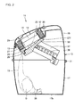
- Figs. 2 and 3 are side cross sections of the waste disposal apparatus of the embodiment.
- Fig. 2 shows a state where a sealing door is closed
- Fig. 3 shows a state where the sealing door is open.
- a waste disposal apparatus 11 includes: an annular waste inlet 16 for inserting a waste material D such as a soiled diaper therethrough; a cylindrical film 15 extending downward from the waste inlet 16 and having its lower end closed by a knot 26; a waste accommodating main body 13 for receiving the waste material D inserted through the waste inlet 16, together with the film 15; and a lid 23 that covers the waste inlet 16 from above.
- the long film 15 is attached to the waste inlet 16.
- the film 15 extends downward so as to cover the opening of the waste inlet 16.
- the waste accommodating main body 13 is a hollow container for storing waste materials D that are placed in the film 15, and is divided into a lower part 17 and an upper part 19.
- the lower part 17 of the waste accommodating main body 13 has a bottom 17b at its lower end, and has an opening at its upper end.
- the upper part 19 of the waste accommodating main body 13 covers, at its lower end, the opening at the upper end of the lower part 17, and has the waste inlet 16 at its upper end.
- An open/close sealing mechanism 28 is provided inside the upper part 19 of the waste accommodating main body 13.
- the sealing mechanism 28 nips the film 15 at a position between the waste inlet 16 and the stored waste material D to seal the stored waste material D.
- the sealing mechanism 28 has a sealing door 33 and a sealing door receiving portion 35. The sealing mechanism 28 will be described later.
- the user When disposing of a waste material D, the user first opens the lid 23 to place the waste material D into the film 15 from the waste inlet 16. Then, the user inserts his/her hand into the waste inlet 16, and pushes the film 15 down together with the waste material D to open the sealing door 33. The waste material D thus pushed down, together with the film 15, passes between the opened sealing door 33 and the sealing door receiving portion 35. The waste material D then drops downward along the film15, and is stored in the waste accommodating main body 13. As soon as the user drops the waste material D to a position below the sealing door 33 and the sealing door receiving portion 35, and removes his/her hand from the waste inlet 16, the sealing door 33 closes to nip the film 15. Since a new length of the film 15 is pulled out from the waste inlet 16, the waste inlet 16 is always supplied with a new length of the film 15.
- Fig. 4 is an enlarged cross section of the sealing mechanism 28 of Fig. 2 when the sealing door 33 is closed.
- Fig. 5 is an enlarged cross section of the sealing mechanism 28 of Fig. 3 when the sealing door 33 is open. Note that line O in Fig. 4 represents the central axis of the waste inlet 16 and a tubular core described later.
- the waste disposal apparatus 11 includes the open/close sealing mechanism 28 that nips the film 15 at a position between the waste inlet 16 and the waste material D placed in the waste accommodating main body 13, and seals the waste material D.
- the sealing mechanism 28 has the sealing door 33 and the sealing door receiving portion 35.
- Each of the sealing door 33 and the sealing door receiving portion 35 is provided with a concavo-convex shape so that, upon closing of the sealing door 33, the concavo-convex shape of the sealing door 33 engages with the concavo-convex shape of the sealing door receiving portion 35 to nip the film 15 therebetween. This configuration will be described later.
- the sealing door receiving portion 35 is provided inside the upper part 19 of the waste accommodating main body 13 so that the sealing door 33 covers and closes the waste inlet 16 from beneath in the state where the sealing door 33 is closed.
- a guide rail 37 for guiding the sealing door 33 in opening and closing directions is attached to the inner wall of the upper part 19 of the waste accommodating main body 13. The guide rail 37 is positioned so as to extend downward below the sealing door receiving portion 35, and the sealing door 33 slides along the guide rail 37.
- the sealing door 33 is biased toward the sealing door receiving portion 35, and in a normal state, the sealing door 33 is closed in an engaged state with the sealing door receiving portion 35.
- the film 15 is nipped by the sealing door 33 and the sealing door receiving portion 35. If the user pushes the sealing door 33 down, the sealing door 33 slides in the opening direction, namely away from the sealing door receiving portion 35, along the guide rail 37.
- the sealing door 33 is opened, the nipped film 15 is released to allow the waste material D to be inserted into the waste accommodating main body 13.
- each of the sealing door 33 and the sealing door receiving portion 35 is provided with the concavo-convex shape, and the pair of concavo-convex shapes engage with each other when the sealing door 33 is closed.
- the film 15 is nipped by the coneavo-convex shapes of the sealing door 33 and the sealing door receiving portion 35.
- the coneavo-convex shape of the sealing door 33 is formed by a nipping surface 33c that contacts the film 15 when the sealing door 33 is closed.
- the coneavo-convex shape of the sealing door receiving portion 35 is formed by a nipping surface 35c that contacts the film 15 when the sealing door 33 is closed.
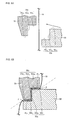
- Fig. 6A is an enlarged side cross section schematically showing film nipping portions of the sealing door 33 and the sealing door receiving portion 35 of the present embodiment when the sealing door 33 is open.
- Fig. 6B is an enlarged side cross section schematically showing the film nipping portions of the sealing door 33 and the sealing door receiving portion 35 of the present embodiment when the sealing door 33 is closed. Note that, to facilitate understanding, Figs. 6A-6B schematically show the film nipping portions of the sealing door 33 and the sealing door receiving portion 35, and do not accurately show an actual configuration of the embodiment.
- the nipping surface 33c which corresponds to the film nipping portion of the sealing door 33, is formed by surfaces 33c 1 , 33c 2 , 33c 3 .
- the surface 33c 1 corresponds to a front end region of the upper surface of the sealing door 33.
- the surface 33c 2 connects to the front end of the surface 33c 1 substantially at a right angle to the surface 33c 1 , and extends downward to form a substantially right angled portion with the surface 33c 1 .
- the surface 33c 3 connects to the lower end of the surface 33c 2 substantially at a right angle to the surface 33c 2 , and extends forward to form a substantially right angled portion with the surface 33c 2 .
- the nipping surface 35c which corresponds to the film nipping portion of the sealing door receiving portion 35, is formed by surfaces 35c 1 , 35c 2 , 35c 3 .
- the surface 35c 1 is provided at the upper end of the film nipping portion so as to extend substantially perpendicularly to the axis O of the waste inlet 16, and is substantially parallel to the surface 33c 1 when the sealing door 33 is closed.
- the surface 35c 2 connects to the front end of the surface 35c 1 substantially at a right angle to the surface 35c 1 and extends downward, and is substantially parallel to the surface 33c 2 when the sealing door 33 is closed.
- the surface 35c 3 connects to the lower end of the surface 35c 2 substantially at a right angle to the surface 35c 2 and extends forward, and is substantially parallel to the surface 33c 3 when the sealing door 33 is closed.
- the film 15 is bent substantially at right angles at two angled portions ⁇ 1 , ⁇ 2 . That is, when nipped by the sealing door 33 and the sealing door receiving portion 35, the film 15 is bent laterally with respect to an imaginary straight line shown by chain line in Fig. 6B at vertical intermediate points ⁇ 1 , ⁇ 2 of the nipped portion of the film 15, so that the vertical intermediate points ⁇ 1 , ⁇ 2 are located on both sides of an imaginary straight line.
- the imaginary straight line is a line connecting an upper end ⁇ and a lower end ⁇ of the nipped portion of the film 15.
- the film 15 is also bent at the upper end ⁇ of the nipped portion of the film 15 by an angled portion formed at the rear end of the surface 35c 1 .
- the film 15 is also bent at the lower end ⁇ of the nipped portion of the film 15 by an angled portion formed at the front end of the surface 33c 3 .
- the waste material D placed in the film 15 is pulled downward by its own weight due to the gravity. That is, the film 15 is continuously subjected to a vertically downward tension by the waste material D. If the film 15 being subjected to such a tension is nipped as shown in Fig. 6B , and is bent at the four angled portions ⁇ 1 , ⁇ 2 , ⁇ , ⁇ , the film 15 is subjected to a higher tension at these angled portions. This effectively closes a remaining airflow path that causes passing of odors in the related art described above. Thus, odor sealing capability can be significantly increased.
- the film 15 need not be twisted upon every disposal of a waste material D, which can avoid the disadvantage that the maximum amount of waste that can be accommodated in the waste disposal apparatus 11 is reduced by the twists of the film 15.
- the concavo-convex shapes having the substantially right angled portions are stepped shapes, and thus are not complex. This facilitates formation of the concavo-convex shapes when mass producing the sealing door 33 and the sealing door receiving portion 35 by a die molding method.
- the waste disposal apparatus 11 of the present embodiment is advantageous in terms of mass production of the products.
- Figs. 7A-7B schematically show another embodiment of the sealing door 33 and the sealing door receiving portion 35.
- Fig. 7A is an enlarged side cross section showing film nipping portions of a convex sealing door 33 and a concave sealing door receiving portion 35 of the present embodiment when the convex sealing door 33 is open.
- Fig. 7B is an enlarged side cross section showing the film nipping portions of the convex sealing door 33 and the concave sealing door receiving portion 35 of the present embodiment when the convex sealing door 33 is closed. Note that, to facilitate understanding, Figs. 7A-7B schematically show the film nipping portions of the sealing door 33 and the sealing door receiving portion 35, and do not accurately show an actual configuration of the embodiment.
- nipping of the film 15 by the sealing door 33 and the sealing door receiving portion 35 is implemented by engagement between the sealing door 33 provided with the film nipping portion having a convex side cross section, and the sealing door receiving portion 35 provided with the film nipping portion having a concave side cross section that is configured to receive the convex shape of the sealing door 33.
- a nipping surface 33c has a ridge 133 having a convex cross section
- a nipping surface 35c has a ridge groove 135 having a concave cross section.
- the ridge 133 protrudes in a direction substantially parallel to the sliding direction of the sealing door 33.
- the nipping surface 33c of the sealing door 33 is formed by surfaces 33c 1 to 33c 5
- the nipping surface 35c of the sealing door receiving portion 35 is formed by surfaces 35c 1 to 35c 5 .
- the surfaces 33c 1 to 33c 5 , 35c 1 to 35c 5 are surfaces that extend substantially perpendicularly to an imaginary straight line connecting an upper end ⁇ and a lower end ⁇ of the nipped portion of the film 15 shown in Fig. 7B .
- the film 15 is bent substantially at right angles at four angled portions ⁇ 1 to ⁇ 4 . That is, the film 15 is bent substantially horizontally between the angled portions ⁇ 1 , ⁇ 2 , and between the angled portions ⁇ 3 , ⁇ 4 .
- the film 15 is pulled vertically downward by the weight of the waste material D due to the gravity. That is, the film 15 is subjected to a high tension at the four substantially right angled portions ⁇ 1 , ⁇ 2 , ⁇ 3 , ⁇ 4 . Thus, a remaining air flow path formed inside of the film 15 is bent at right angles, whereby odors can be more effectively sealed. Moreover, the film 15 need not be twisted upon every disposal of a waste material D, which can avoid the disadvantage that the maximum amount of waste that can be accommodated in the waste disposal apparatus 11 is reduced by the twists of the film 15. Furthermore, the concavo-convex shapes can be easily formed when mass producing the sealing door 33 and the sealing door receiving portion 35 by a die molding method. Thus, the waste disposal apparatus 11 of the present embodiment is advantageous in terms of mass production of the products.
- the waste disposal apparatus 11 further includes a spring 39 for continuously biasing the sealing door 33 toward the sealing door receiving portion 35.
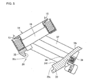
- Fig. 8 is an exploded perspective view of a film accommodating portion 14.
- the waste disposal apparatus 11 includes the film accommodating portion 14, which forms the waste inlet 16 and also accommodates the film 15.
- the film accommodating portion 14 is detachably attached to a film attachment portion 12 provided at an upper region of the upper part 19 of the waste accommodating main body 13, and forms the outline of the waste inlet 16.
- the film accommodating portion 14 has a cylindrical tubular core 27 extending downward from the waste inlet 16, a tubular core flange 27f provided at the lower end of the tubular core 27, and a film holding flange 29 that is fitted and fixed to the upper end of the tubular core 27.
- the film 15 is accordion folded in the axial direction of the tubular core 27, and is coaxially inserted on the outer diameter side of the tubular core 27.
- the film holding flange 29 is fitted and connected to the tubular core 27 so as to prevent the film 15 from coming off from the tubular core 27. That is, by the film holding flange 29 located at the upper end of the tubular core 27, and the tubular core flange 27f located at the lower end of the tubular core 27, the film 15 is compressed in the accordion folded state and accommodated in the space between the upper and lower ends in the direction of the axis O of the tubular core 27.
- the film 15 is a consumable part of the film accommodating portion 14. If the film 15 accommodated in the film accommodating portion 14 runs out, the user replaces the used film accommodating portion 14 in the film attachment portion 12 with a refill film accommodating portion 14.
- the film accommodating portion 14 may be configured so that only the film 15 is replaced with a refill film when the film 15 accommodated in the film accommodating portion 14 runs out. That is, the tubular core flange 27f may be fixed to the film attachment portion 12, and the film holding flange 29 may be detachably attached to the tubular core 27. This configuration enables the user to replace only the film 15 with a refill film by removing the film holding flange 29.
- the user pulls out an end of the film 15, which is accommodated in the compressed state on the tubular core 27, upward beyond the outer edge of the film holding flange 29 without closing the lid 23. Then, the user ties a knot 26 at this end of the film 15 to close the film 15. The user pushes the knot 26 down through the tubular core 27 to the bottom 17b while pulling the film 15 out of the film accommodating portion 14.
- waste materials such as soiled diapers into the film 15
- the waste materials are accumulated in the film 15, and the film 15 accordion folded on the outer diameter side of the tubular core 27 is pulled out in the downward direction upon each disposal.
- the user can successively dispose of waste materials into the waste accumulating main body 13.
- the film accommodating portion 14 is supported by the upper part 19 of the waste accommodating main body 13 so that the direction of the axis O of the tubular core 27, namely the opening direction of the waste inlet 16, is tilted at a predetermined angle.
- the waste inlet 16 is tilted forward at a predetermined angle ⁇ 16 with respect to the vertical direction. This makes it easier for mothers to dispose of soiled diapers into the waste disposal apparatus 11. This will be described briefly below. Mothers typically lay their children down on the floor to change diapers. Namely, mothers typically sit on the floor while changing diapers. According to the present embodiment, since the waste inlet 16 is tilted at the predetermined angle ⁇ 16 , mothers can easily insert soiled diapers (waste materials) through the waste inlet 16 without standing up after changing diapers in a sitting posture.
- the film accommodating portion 14 may be supported by the upper part 19 of the waste accommodating main body 13 so that the opening direction of the waste inlet 16 is horizontal.
- the axis O of the tubular core 27 extends horizontally. In this configuration as well, a tension can be applied to the nipped portion of the film.
- the sealing door 33 has a substantially flat upper surface 34.
- the shape of the upper surface 34 will be described in detail later.
- the sealing door 33 is supported by the upper part 19 of the waste accommodating main body 13 so that the upper surface 34 of the sealing door 33 is tilted at a predetermined angle corresponding to the direction of the tilted axis of the tubular core 27. That is, the sealing door 33 is supported by the upper part 19 of the waste accommodating main body 13 so that, in the closed state, the sealing door 33 is tilted at a predetermined angle with its front end side being located lower in the vertical direction, and its rear end side being located higher in the vertical direction.
- the sealing door 33 advances and withdraws at the predetermined angle to and from the sealing door receiving portion 35.
- An advancing/withdrawing direction S of the sealing door 33 is tilted at an angle different from that of the axis O of the tubular core 27.
- ⁇ 16 represents a tilt angle of the waste inlet 16 (the tubular core 27) with respect to the vertical direction
- ⁇ 33 represents a tilt angle of the advancing/withdrawing direction S of the sealing door 33 with respect to the vertical direction.
- the tilt angle ⁇ 33 of the advancing/withdrawing direction S of the sealing door 33 is larger than the tilt angle ⁇ 16 of the waste inlet 16.
- the sealing door 33 is translated downward and backward, and thus away from the axis O of the tubular core 27. That is, when being opened, the sealing door 33 can be sufficiently separated from the film 15.
- the film 15 is opened wide when the sealing door 33 is opened, which enables the user to easily insert a waste material D into the waste accommodating main body 13 while sitting on the floor.
- the tubular core flange 27f which is positioned so as to surround the lower end of the tubular core 27 and corresponds to the lower end of the film accommodating portion 14, is supported by the waste accommodating main body 13 so as to be tilted at a predetermined angle. That is, as shown in Figs. 2-5 , the front end side of the tubular core flange 27f is located lower in the vertical direction, and the rear end side thereof is located higher in the vertical direction.
- the nipping surface 35c of the sealing door receiving portion 35 is located near the lowest part of the tubular core flange 27f. This facilitates nipping of the film 15 by the sealing door 33. This will be described below.
- the sealing door 33 is open, the film 15 is pulled vertically downward by the weight of the waste material D placed in the film 15, and thus extends substantially straight downward from the waste inlet 16.
- the tubular core 27 is tilted at the predetermined angle ⁇ 16 .
- the film 15 is naturally drawn toward the lower side of the tilt, namely toward the front side, at least by a horizontal distance L 0 (1- cos ⁇ 0 ) if the film 15 extends straight downward from the waste inlet 16.
- the film 15 is nipped by the sealing door 33 and the sealing door receiving portion 35 at a position on the lower side of the tilt to which the film 15 is naturally drawn. This can facilitate nipping of the film 15 by the sealing door 33, whereby sealing for blocking passing of odors can be more efficiently performed.
- the upper surface 34 of the sealing door 33 is substantially flat, as described above.
- the upper surface 34 of the sealing door 33 is formed by a substantially flat front part 34f, and a rear part 34r that is gently curved so as to be tilted with respect to the front part 34f. This will be described below with reference to Fig. 4 .
- the film accommodating portion 14 is supported in a tilted state by the upper part 19 of the waste accommodating main body 13 so that the front side of the film accommodating portion 14 is located lower than the rear side thereof.
- the sealing door 33 nips the film 15 by engaging with the sealing door receiving portion 35 on the front side thereof, namely on the lower side of the tilt.
- the nipping surface 35c of the sealing door receiving portion 35 is present between the film accommodating portion 14 and the front part 34f of the upper surface 34 of the sealing door 33.
- the nipping surface 35c of the sealing door receiving portion 35 is not present between the film accommodating portion 14 and the rear part 34r of the upper surface 34 of the sealing door 33.
- the upper surface 34 of the sealing door 33 is formed by two different surfaces (the flat front part 34f and the tilted rear part 34r) in order to contact the sealing door receiving portion 35 to close the waste inlet 16 from beneath.
- the upper surface 34 of the sealing door 33 is formed so as to satisfy the following expression (2), where ⁇ 34f represents an angle of the front part 34f with respect to the horizontal plane, and ⁇ 34 , represents an angle of the rear part 34r with respect to the horizontal plane. 0 ⁇ ° ⁇ ⁇ 34 ⁇ f ⁇ ⁇ 34 ⁇ r
- the user can efficiently transmit the pushing force to the sealing door 33.
- the user can open the sealing door 33 with a smaller force.
- the rear part 34r of the upper surface 34 may be substantially perpendicular to the advancing/withdrawing direction S. According to this modification, the pushing force that is applied from the user's hand to the sealing door 33 can be applied to the spring 39 without being reduced. Thus, the user can push the sealing door 33 open with a smaller force.
- Fig. 9 is an overall perspective view of a main body lock mechanism 25 and a lid lock mechanism 24 of the present embodiment.
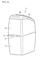
- Fig. 10 is an overall perspective view of the waste disposal apparatus 11 of the present embodiment as viewed obliquely from behind.
- Fig. 11 is an enlarged side cross section of the main body lock mechanism 25 and the lid lock mechanism 24.
- the upper part 19 and the lower part 17 of the waste accommodating main body 13 are closed so that the upper part 19 covers at its lower end a main body opening 17h located at the upper end of the lower part 17.
- the film attachment portion 12 is provided at an upper region of the upper part 19 of the waste accommodating main body 13, and the film accommodating portion 14 is attached to the film attachment portion 12.
- a main body hinge 31 is provided on the back face of the waste accommodating main body 13.
- the main body hinge 31 is provided substantially in the middle of the vertical height of the waste disposal apparatus 11.
- the upper part 19 of the waste accommodating main body 13 is pivotally attached to the lower part 17 thereof by the main body hinge 31, and is pivotable about the main body hinge 31 as a fulcrum. As the upper part 19 of the waste accommodating main body 13 is pivoted, the main body opening 17h at the upper end of the lower part 17 is open to the outside.
- the main body lock mechanism 25 and a main body unlock mechanism are provided on the front face of the waste accommodating main body 13.
- the main body lock mechanism 25 prevents pivoting of the upper part 19 in the state where the upper part 19 covers the lower part 17, namely in the state where the upper part 19 closes the lower part 17.
- the main body unlock mechanism is a mechanism for unlocking the main body lock mechanism 25.
- the main body lock mechanism 25 has a columnar main body push button 21, and a push button receiving hole 32 that is formed as a through hole in the upper part 19 of the waste accommodating main body 13 in order to latch and lock the main body push button 21.
- the main body push button 21 is formed at the upper end of a vertical flexible pillar portion 21p.
- the lower end of the pillar portion 21p is connected to the upper end of the lower part 17 of the waste accommodating main body 13.
- the main body push button 21 is a column that protrudes in the outer diameter direction of pivoting of the upper part 19 of the waste accommodating main body 13.
- a push button outer peripheral edge 21g which is an outer peripheral edge of the column, engages with the push button receiving hole 32 formed in the lower end of the upper part 19, thereby preventing pivoting of the upper part 19.
- the main body unlock mechanism includes the main body push button 21 as an operation portion for unlocking the main body lock mechanism 25, and an opening operation portion for placing a user's hand thereon to pivot and open the upper part 19 of the waste accommodating main body 13 after unlocking the main body lock mechanism 25.
- the upper part 19 of the waste accommodating main body 13 has a handle 22 as the opening operation portion.
- the handle 22 is provided at the lower end of the front face of the upper part 19, which is located on the side away from and opposite to the back face of the upper part 19 to which the main body hinge 31 is attached.
- the handle 22 is positioned near and below the main body push button 21.
- the main body push button 21 is disengaged from the push button receiving hole 32 and the main body lock mechanism 25 is unlocked only while the main body push button 21 is being pressed. If the user releases the main body push button 21, the pillar portion 21p is restored to its original position, and the main body lock mechanism 25 is locked again.
- the user empties the waste accommodating main body 13 by unlocking the main body lock mechanism 25 and opening the upper part 19 of the waste accommodating main body 13.
- Fig. 12 is a perspective view illustrating the operation of unlocking the main body lock mechanism 25.
- the user places four fingers, namely fingers other than the thumb, of one hand on the handle 22 from beneath, and at the same time presses with the thumb the main body push button 21 located near and above the handle 22, thereby unlocking the main body lock mechanism 25.
- the user lifts the handle 22 while unlocking the main body lock mechanism 25.
- the upper part 19 of the waste accommodating main body 13 is pivoted toward the back face, and the waste accommodating main body 13 is opened.
- Fig. 13 is a side cross section showing the state where the upper part 19 of the waste accommodating main body 13 of the present embodiment has been fully pivoted.
- the user when emptying the waste accommodating main body 13 that is filled with waste materials D, the user first fully opens the upper part 19 of the waste accommodating main body 13, and cuts the film 15 with a film cutter 38. Then, the user ties a knot to close the cut face of the film 15, and removes the bag of the film 15 filled with the waste materials D from the waste accommodating main body 13 to throw the bag out.
- the user places the upper part 19 of the waste accommodating main body 13 over the lower part 17 thereof.
- the push button 21 engages with the push button receiving hole 32, and the upper part 19 of the waste accommodating main body 13 is locked again.
- the main body push button 21 is positioned near and above the handle 22 so that, when unlocking the main body lock mechanism 25 to pivot and open the upper part 19 of the waste accommodating main body 13, an adult user can press the main body push button 21 with other finger while supporting the handle 22 with any of the fingers of his/her one hand.
- the main body push button 21 is positioned on a path the thumb is ergonomically most likely to follow naturally when the user places the other four fingers on the handle 22 from beneath and closes his/her hand with the four fingers as a fulcrum.
- the user In order to unlock the main body lock mechanism 25 to open the upper part 19 of the waste accommodating main body 13, the user needs to press the main body push button 21 in the inner diameter direction that is substantially perpendicular to the pivoting direction of the upper part 19, and to lift the handle 22 to pivot the upper part 19.
- the waste disposal apparatus 11 is easy to handle when throwing out the waste materials D stored in the waste accommodating main body 13.
- the lid 23 is pivotally attached, at its end on the back side, to the upper end of the upper part 19 of the waste accommodating main body 13 by a lid hinge 30, and the lid 23 is pivotable about the lid hinge 30 as a fulcrum.
- the lid 23 is pivoted to open, the waste inlet 16 is open to the outside as shown in Fig. 1 .
- the waste disposal apparatus 11 includes a lid lock mechanism 24, and a lid unlock mechanism.
- the lid lock mechanism 24 prevents pivoting of the lid 23 in the state where the lid 23 covers the waste inlet 16, namely in the state where the lid 23 is closed.
- the lid unlock mechanism is a mechanism for unlocking the lid lock mechanism 24.
- the lid lock mechanism 24 has a lid push button 20, and a lid push button receiving portion 36 provided in the upper part 19 of the waste accommodating main body 13.
- the lid push button 20 is provided in the lower part of the front face of the lid 23.
- a lid push button hook 20h is formed at the lower end of the lid push button 20. The lid push button hook 20h moves integrally with the lid push button 20.
- the lid push button receiving portion 36 is formed at the upper end of the upper part 19 of the waste accommodating main body 13. When the lid 23 is in the closed state, the lid push button receiving portion 36 engages with the lid push button hook 20h.
- the lid unlock mechanism includes the lid push button 20 as an operation portion for unlocking the lid lock mechanism 24, and an opening operation portion for placing a user's hand thereon to pivot and open the lid 23 after unlocking the lid lock mechanism 24.
- the lid 23 has a lid handle 18 on the front face side of the lid 23.
- the lid handle 18 is positioned near and above the lid push button 20.
- Fig. 14 is a perspective view illustrating the operation of unlocking the lid lock mechanism 24.
- the lid push button 20 When the user places four fingers, namely the fingers other than the thumb, of his/her one hand on the lid handle 18 from above, and presses the lid push button 20 by the thumb, the lid push button 20 together with the lid push button hook 20h moves in the pressing direction, and the lid push button hook 20h is disengaged from the lid push button receiving portion 36, whereby the lid lock mechanism 24 is unlocked.
- the user lifts the lid handle 18 while pressing the lid push button 20 with the thumb and unlocking the lid lock mechanism 24.
- the lid 23 is pivoted toward the back face, and the waste inlet 16 is opened.
- the lid push button hook 20h is restored to its original position, and is engaged again with the lid push button receiving portion 36, whereby the lid lock mechanism 24 is locked.
- the lid push button hook 20h is disengaged from the lid push button receiving portion 36 only while the lid push button 20 is being pressed. That is, if the user releases the lid push button 20, the lid lock mechanism 24 is locked again.
- the waste disposal apparatus 11 is easy to handle when inserting waste materials through the waste inlet 16.
- the user can place the four fingers other than the thumb of his/her one hand on the lid handle 18 from above, and at the same time press the lid push button 20 located near and below the lid handle 18 with the thumb. That is, the operator can unlock the lid lock mechanism 24 according to the user's movement of naturally closing his/her hand.
- the lid push button 20 is positioned on a path the thumb is ergonomically most likely to follow naturally when the user places the other four fingers on the lid handle 18 from above and closes his/her hand with the four fingers as a fulcrum. This makes it easier and more comfortable for the user to unlock the lid lock mechanism 24 to pivot and open the lid 23.
- FIG. 15 is a side cross section of a waste disposal apparatus 41 of the further embodiment of the present invention when a sealing door 53 is closed.
- Fig. 16 is a side cross section of the waste disposal apparatus 41 of the further embodiment when the sealing door 53 is open.
- Fig. 17 is a perspective view of a sealing mechanism 48 in Fig. 16 as viewed obliquely from below. Note that in the following description, components similar to those of the embodiments described with reference to Figs. 1 to 14 are denoted by the same reference characters as those of Figs. 1 to 14 , and detailed description thereof will be omitted.
- the waste disposal apparatus 41 includes: a waste inlet 16 for inserting a waste material D therethrough; a cylindrical film 15 extending downward from the waste inlet 16 and having its lower end closed by a knot 26; a waste accommodating main body 43 for receiving the waste material D inserted through the waste inlet 16, together with the film 15; and a lid 23 that covers the waste inlet 16 from above.
- the waste accommodating main body 43 is a hollow container for storing waste materials D that are placed in the film 15, and is divided into a lower part 47 and an upper part 49.
- the lower part 47 of the waste accommodating main body 43 has a bottom 47b at its lower end.
- a slope portion 42 is provided on the front side of the bottom 47b.
- the slope portion 42 is provided on the bottom 47b so as to form a tilted surface whose vertical height decreases from the front side to the rear side.
- the lower part 47 of the waste accommodating main body 43 has an opening at its upper end.
- the upper part 49 of the waste accommodating main body 43 covers, at its lower end, the opening at the upper end of the lower part 47.
- the waste inlet 16 is formed in the upper end of the upper part 49.
- a tubular pillar portion 44 is provided in the rear part of the upper end of the upper part 49 of the waste accommodating main body 43.
- the tubular pillar portion 44 is a hollow pillar portion that extends vertically downward from the upper end of the upper part 49.
- a film cutter 38 described above is attached to the lower end of the tubular pillar portion 44.
- the vertical length of the tubular pillar portion 44 is determined so that the film cutter 38 attached to the lower end of the tubular pillar portion 44 is located at about the same height or lower than a main body hinge 31 in the vertical direction. This configuration will be described briefly below.
- the user when emptying the waste accommodating main body 43 that is filled with waste materials D, the user first fully opens the upper part 49 of the waste accommodating main body 43 to the state shown in Fig. 13 . Then, the user cuts the film 15 with the film cutter 38. If the vertical length of the tubular pillar portion 44 is less than the value determined as described above, the film cutter 38 is contained in the space in the upper part 49 of the waste accommodating main body 43 in the state where the upper part 49 is open. This makes it difficult for the user to cut the film 15. Thus, the vertical length of the tubular pillar portion 44 is determined as described above so that the film cutter 38 protrudes outside the upper part 49 of the waste accommodating main body 43 in the state where the upper part 49 is open. Note that the configuration of the lower part 47 and the upper part 49 of the accommodating main body 43 is similar to that of the above embodiments except for the slope portion 42 and the tubular pillar portion 44.
- an open-close sealing mechanism 48 for nipping the film 15 at a position between the waste inlet 16 and the stored waste material D to seal the waste material D is provided inside the upper part 49 of the waste accommodating main body 43.
- the sealing mechanism 48 includes: a sealing door receiving portion 55 that is coupled with the lower end of a film attachment portion 12 provided at an upper region of the upper part 49; and a sealing door 53 that is located below the sealing door receiving portion 55, and engages with the sealing door receiving portion 55 to form a film nipping portion.
- the sealing door receiving portion 55 is an annular member that is provided below the film attachment portion 12 and along the inner diameter surface of a tubular core 27.
- the sealing door 53 is a plate-like member that is larger than a central hole of the sealing door receiving portion 55, and covers the central hole of the sealing door receiving portion 55 from beneath.
- the sealing door 53 forms, at its front end, the film nipping portion together with the sealing door receiving portion 55, and is pivotally supported at its rear end by the sealing door receiving portion 55 via a sealing mechanism hinge 45 as a fulcrum. That is, the opening/closing operation of the sealing door 53 is implemented by pivoting. As shown in Fig. 15 , when in the closed state, the sealing door 53 engages with the sealing door receiving portion 55 to nip the film 15. As in the above embodiments, this closes a remaining airflow path that causes passing of odors.
- the film nipping portion which is formed by the sealing door 53 and the sealing door receiving portion 55, will be described below.
- the film nipping portions of the sealing door 53 and the sealing door receiving portion 55 includes stepped concavo-convex shapes, and the sealing door 53 engages with the sealing door receiving portion 55 when in the closed position. More specifically, the film nipping portion of the sealing door 53 has a nipping surface 53c that contacts the film 15, while the film nipping portion of the sealing door receiving portion 55 has a nipping surface 55c that contacts the film 15.
- the nipping surface 53c of the sealing door 53 is formed by surfaces 53c 1 , 53c 2 , and 53c 3 .
- the surface 53c 1 corresponds to a front end region of the upper surface of the sealing door 53.
- the surface 53c 2 connects to the front end of the surface 53c 1 substantially at a right angle to the surface 53c 1 , and extends downward to form a circular arc surface along the entire width of the front end of the sealing door 53.
- the surface 53c 3 connects to the lower end of the surface 53c 2 substantially at a right angle to the surface 53c 2 , and extends forward to form a substantially right angled portion with the surface 53c 2 .
- the nipping surface 55c of the sealing door receiving portion 55 is formed by surfaces 55c 1 , 55c 2 , and 55c 3 .
- the surface 55c 1 is provided at the upper end of the film nipping portion so as to extend substantially perpendicularly to the axis O of the waste inlet 16, and is substantially parallel to the surface 53c 1 when the sealing door 53 is closed.
- the surface 55c 2 connects to the front end of the surface 55c 1 substantially at a right angle to the surface 55c 1 , and extends downward to form a circular arc surface that is substantially parallel to the surface 53c 2 when the sealing door 53 is closed.
- the surface 55c 3 connects to the lower end of the surface 55c 2 substantially at a right angle to the surface 55c 2 and extends forward, and is substantially parallel to the surface 53c 3 when the sealing door 53 is closed.
- the sealing mechanism 48 further includes a spring 69 that biases the sealing door 53 in the closing direction, and spring covers 46 that cover the spring 69.
- the spring 69 is a single helical extension spring capable of extending and contracting in its extending direction, and both ends of the spring 69 are coupled with right and left side edges of the sealing door receiving portion 55.
- a central region of the spring 69 is accommodated in a spring guide 63 provided in the lower surface of the sealing door 53.
- the spring guide 63 is a groove formed in the lower surface of the sealing door 53.
- the spring guide 63 is provided in the longitudinal central portion of the lower surface of the sealing door 53 so as to extend along the entire lateral width of the lower surface of the sealing door 53.
- the spring 69 is a single helical extension spring, and the central region of the spring 69 extends laterally along the lower surface of the sealing door 53 so as to be accommodated in the spring guide 63 provided in the lower surface of the sealing door 53.
- the sealing door 53 is stably and laterally substantially equally biased by the spring 69. This will be described below.
- the spring 69 biases the sealing door 53 in the closing direction by using the right and left side edges of the sealing door receiving portion 55, with which both ends of the spring 69 are coupled, as a fixed point, and using the entire lateral width of the longitudinal central portion of the lower surface of the sealing door 53 as a working point. Since the spring 69 is a helical extension spring, the spring 69 bilaterally symmetrically applies a substantially uniform elastic force to the lower surface of the sealing door 53. Moreover, since the spring 69 is latched by the spring guide 63, the spring 69 is stably fixed to a predetermined position on the lower surface of the sealing door 53. With these configurations, the sealing door 53 is stably and laterally substantially equally biased toward the sealing door receiving portion 55. That is, a pressing force is substantially evenly distributed in the film nipping portions of the sealing door 53 and the sealing door receiving portion 55.
- the spring covers 46 are members having a C-shaped cross section and extending from the sealing door 53 to the sealing door receiving portion 55, and accommodate both side portions of the spring 69.
- the upper end of each spring cover 46 is pivotally supported by the sealing door receiving portion 55 by using as a fulcrum a hinge 50 that is provided near the coupling point between the spring 69 and the sealing door receiving portion 55.
- Each spring cover 46 has a groove recess 51, which is formed in its side surface facing the sealing door 53 so as to be recessed in the direction to the inside the spring cover 46.
- the groove recess 51 is a groove that extends from the upper end to the lower end of the spring cover 46.
- the groove recess 51 is open to the side edge of the sealing door 53.
- Rail-like pawls 56 are provided on both sidewalls of the groove.
- the pawls 56 extend from the upper end to the lower end of the spring cover 46.
- the pawls 56 engage with a hook portion (not shown) that is provided so as to protrude outward from the central portion of the side edge of the sealing door 53.
- the pawls 56 and the hook portions of the sealing door 53 engage with each other so as to be relatively slidable with respect to each other along the extending direction of the spring cover 46.
- the sealing door 53 slides along the extending direction of the spring cover 46.
- the spring covers 46 are pivotally supported by the sealing door receiving portion 55.
- each spring cover 56 can smoothly pivot so as to follow a circular arc-shaped path that is followed by the engaged portion between the sealing door 53 and the spring cover 46 when the sealing door 53 is opened/closed.
- the spring covers 46 are positioned on the right and left side edges of the sealing door 53 and the sealing door receiving portion 55 so as to contain the spring 69 in the groove recesses 51 of the spring covers 46. With these configurations, the spring 69 is always accommodated in the groove recesses 51 regardless of the opening/closing operation of the sealing door 53.
- FIG. 15-17 A method for disposing of a waste material D in the waste disposal apparatus 41 according to the further embodiment of the present invention will be described with reference to Figs. 15-17 .
- the user first opens the lid 23 to place the waste material D in the film 15 through the waste inlet 16. Then, the user inserts his/her hand into the waste inlet 16, and pushes the film 15 down together with the waste material D to push the sealing door 53 down.
- the sealing door 53 pivots with the sealing mechanism hinge 45 as a fulcrum so as to follow a circular arc-shaped path shown by arrow A in Fig. 16 , whereby the sealing door 53 is opened.
- the waste material D then drops downward along the film15 as shown by arrow B in Fig. 16 , and is stored in the lower part 47 of the waste accommodating main body 43.
- the slope portion 42 is provided on the front side of the bottom 47b of the lower part 47 of the waste accommodating main body 43.
- the waste material D slides down toward the back face of the lower part 47 as shown by arrow C in Fig. 16 along the slope portion 42 provided in a region corresponding to the position to which the waste material D is supposed to drop. This prevents the waste materials D from being stored only in the front region of the lower part 47 of the waste accommodating main body 43, and thus enables the waste materials D to be evenly stored in the lower part 47.
- the user After placing the waste material D in the lower part 47 of the waste accommodating main body 43, the user removes his/her hand from the waste inlet 16.
- the sealing door 53 then immediately closes to nip the film 15.
- the film 15 nipped by the sealing door 53 and the sealing door receiving portion 55 is bent substantially at right angles at two angular portions formed in the film nipping portions. That is, an imaginary straight line, which connects the upper and lower ends of the film nipping portions, is bent substantially horizontally in the film nipping portions. This closes a remaining airflow path, which causes passing of odors, at right angles, whereby the passing of odors can be effectively blocked.
- the opening/closing operation of the sealing door 53 is implemented by pivoting of the sealing door 53 about the sealing mechanism hinge 45 as a fulcrum.
- the user can easily open the sealing door 53 when pressing the waste material D into the waste accommodating main body 43, which facilitates the waste disposal operation.
- the sealing mechanism 48 of the waste disposal apparatus 41 of the present embodiment further has the spring covers 46 that cover the spring 69.
- the spring 69 is always accommodated in the groove recesses 51 of the spring covers 46 regardless of the opening/closing operation of the sealing door 53.
- This configuration can prevent the film 15 from being damaged by being caught by the spring 69 positioned on both side surfaces (the right and left surfaces) of the sealing door 53, when the user opens/closes the sealing door 53 for disposal of the waste material D.
- both ends of the spring 69 are guided by the spring covers 46 so as to be always positioned inside the groove recesses 51. This can prevent the spring 69 from coming off from the sealing door 53 even if the spring guide 63 is not provided in the lower surface of the sealing door 53.
- each of the nipping surfaces 53c, 55c which correspond to the film nipping portions of the sealing door 53 and the sealing door receiving portion 55, is formed by flat surfaces and a circular arc surface that is substantially at right angles with the flat surfaces.
- the present invention is not limited to this, and the flat surfaces and a circular arc surface may cross each other at a predetermined angle such as an acute or obtuse angle.
- the sealing door 53 and the sealing door receiving portion 55 may be configured so that each of the nipping surfaces 53c, 55c may consist of a plurality of flat surfaces, a plurality of curved surfaces, or a plurality of flat and curved surfaces.
- an elastic member for biasing the sealing door 53 in the closing direction is the spring 69 that is a single helical extension spring.
- the present invention is not limited to this, and any type of spring may be used, and a plurality of springs may be used. Alternatively, a rubber material, a resin material, or a mixture thereof may be used as the elastic member.
- the sealing door 53 may be magnetically biased in the closing direction by incorporating a permanent magnet or an electromagnet into the sealing door 53 and the sealing door receiving portion 55.
- FIG. 18 is a perspective view of the film accommodating cassette 54 according to the further embodiment of the present invention.
- Fig. 19 is a perspective view of the film accommodating cassette 54 of Fig. 18 having the film 15 removed therefrom.
- Fig. 20 is a side view of the film accommodating cassette 54 in the state of Fig. 19 .
- Fig. 21 is a top view of the film accommodating cassette 54 in the state of Fig. 19 as viewed from above in the direction of the axis O of a tubular core 57.
- the waste disposal apparatus 41 includes the film accommodating cassette 54, which forms the waste inlet 16 and also accommodates the film 15.
- the film accommodating cassette 54 which is a film accommodating portion, has the cylindrical tubular core 57 defining the waste inlet 16, a tubular core flange (a lower flange) 57f extending from the lower end of the tubular core 57 in the outer diameter direction (radially outward), and a film holding flange (an upper flange) 59 extending from the upper end of the tubular core 57 in the outer diameter direction.
- the film 15 is accommodated in an accordion folded state in a space between the axial upper and lower ends of the tubular core 57 by the film holding flange 59 located at the upper end of the tubular core 57 and the tubular core flange 57f located at the lower end of the tubular core 57.
- the long film 15 can be accommodated in a compressed state between the tubular core flange 57f and the film holding flange 59.
- the radial dimension of the film holding flange 59 is relatively smaller than that of the tubular core flange 57f. This enables the film 15 to be pulled out beyond the outer edge of the film holding flange 59, whereby the film 15 can be extended downward through the waste inlet 16 formed in the tubular core 57.
- cutouts 58 are provided in the outer edge of the tubular core flange 57f so as to extend through the tubular core flange 57f along the direction of the axis O thereof. As shown in Fig. 21 , the tubular core flange 57f has the cutouts 58 at intervals of about 120° in the circumferential direction based on the axis O. These cutouts 58 are provided at the three positions of the tubular core flange 57f in a substantially rotational symmetrical pattern based on the axis O.
- An upper surface 60 and a lower surface 64 of the tubular core flange 57f are flat surfaces that extend substantially parallel to each other.
- a rib 61 is provided on the upper surface 60.
- the rib 61 is formed by a circumferential rib (annular rib) 61a, a plurality of radial ribs 61b, and engagement ribs 61c 1 , 61c 2 .
- the circumferential rib 61a is formed at a predetermined radial position on the upper surface 60 so as to extend continuously in the circumferential direction about the axis O.
- the plurality of radial ribs 61b extend radially from the outer peripheral surface of the tubular core 57 to the circumferential rib 61a, and are arranged at substantially regular intervals in the circumferential direction.
- the engagement ribs 61c 1 , 61c 2 extend radially from the circumferential rib 61a to the outer edge of the tubular core flange 57f.
- the engagement ribs 61c 1 (first engagement rib), 61c 2 (second engagement rib) are substantially equally arranged on the upper surface 60 of the tubular core flange 57f at intervals of about 60° in the circumferential direction based on the axis O.
- the engagement ribs 61c 1 are located at positions corresponding to one circumferential ends of the cutouts 58. That is, in the present embodiment, the three engagement ribs 61c 1 are provided at the clockwise ends of the cutouts 58 as viewed from above in the direction of the axis O.
- the three engagement ribs 61c 1 and the three engagement ribs 61c 2 are arranged at substantially regular intervals of about 60° in the circumferential direction.
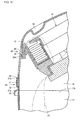
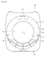
- FIG. 22 is a diagram showing the appearance of the waste disposal apparatus 41 of the further embodiment of the present invention with the film accommodating cassette 54 removed therefrom, as viewed from above in the direction of the axis O.
- the axis O in Fig. 22 represents the central axis of the tubular core 57 in the state where the film accommodating cassette 54 is attached to the waste disposal apparatus 41, and the axis O substantially corresponds to the central axis of an inner peripheral surface 12a of the film attachment portion 12.
- the axis O in Fig. 22 is a line that extends perpendicularly to the plane of the paper of the figure.
- the film attachment portion 12 which forms a space for attaching the film accommodating cassette 54, is provided at an upper region of the upper part 49 of the waste accommodating main body 43.
- the film attachment portion 12 includes the inner peripheral surface 12a and a bottom surface 12b.
- the inner peripheral surface 12a faces a side of the film accommodating cassette 54 when the film accommodating cassette 54 is attached to the film attachment portion 12.
- the bottom surface 12b is a flat surface that contacts the lower surface 64 of the tubular core flange 57f when the film accommodating cassette 54 is attached to the film attachment portion 12.
- the axis O of the inner peripheral surface 12a of the film attachment portion 12 substantially corresponds to the axis O of the tubular core 57.
- a circular opening 12h is formed about the axis O in the central portion of the bottom surface 12b of the film attachment portion 12 so as to communicate with the space inside the inner peripheral surface of the tubular core 57 that forms the waste inlet 16.
- the sealing door 53 covers and closes the opening 12h from beneath.
- Pawls 62 (main body-side latching portion) are provided on the inner peripheral surface 12a of the film attachment portion 12 at a predetermined height from the bottom surface 12b in the upper direction of the axis O.
- the pawls 62 protrude from the inner peripheral surface 12a in the inner diameter direction (radially inward).
- three pawls 62 are provided on the inner peripheral surface 12a of the film attachment portion 12 at regular intervals of about 120° in the circumferential direction based on the axis O. These pawls 62 are thus provided at the three positions in a substantially rotational symmetrical pattern based on the axis O.
- the pawls 62 are formed so that the circumferential width of the pawls 62 is smaller than that of the cutouts 58. This configuration will be described below.
- the user When attaching the film accommodating cassette 54 to the waste disposal apparatus 41, the user places the film accommodating cassette 54 into the film attaching portion 12 with the tubular core flange 57f facing downward, and matches the positions of the pawls 62 provided on the inner peripheral surface 12a of the film attachment portion 12 with the positions of the cutouts 58 provided in the outer edge of the tubular core flange 57f. Then, the user pushes the film accommodating cassette 54 toward the bottom surface 12 of the film attachment portion 12.
- the pawls 62 pass through the cutouts 58, and the lower surface 64 of the tubular core flange 57f contacts the bottom surface 12b of the film attachment portion 12.
- the user turns the film accommodate cassette 54 clockwise in the circumferential direction as viewed from above in the direction of the axis O.
- the outer edge of the tubular core flange 57f enters the gaps between each pawl 62 and the bottom surface 12b of the film attachment portion 12.
- the user continues to turn the film accommodating cassette 54 until the pawls 62 contact the engagement ribs 61c 2 (second engagement rib) and restrict turning of the film accommodating cassette 54.
- the film accommodating cassette 54 is attached to the waste disposal apparatus 41 in this manner.
- the film accommodating cassette 54 of the present embodiment includes a coupling mechanism (cassette-side latching portion) for attaching the film accommodating cassette 54 to the waste disposal apparatus 41, and the coupling mechanism is formed by the outer edge of the tubular core flange 57f that engages with the pawls 62 (main body-side latching portion) of the waste disposal apparatus 41, and the cutouts 58 for introducing coupling/decoupling of the film accommodating cassette 54.
- This embodiment can prevent the film accommodating cassette 54 from coming off in the state where the upper part 49 of the waste accommodating main body 43 is open as shown in Fig. 13 .
- the user When detaching the film accommodating cassette 54 from the waste disposal apparatus 41, the user turns the film accommodating cassette 54 counterclockwise in the circumferential direction as viewed from above in the direction of the axis O.
- the pawls 62 contact the engagement ribs 61c 1 (first engagement rib), and restrict turning of the film accommodating cassette 54.
- the engagement ribs 61c 1 are provided at the clockwise ends of the cutouts 58.
- the positions of the pawls 62 substantially match the positions of the cutouts 58 as soon as the pawls 62 contact the engagement ribs 61c 1 . Accordingly, the film accommodating cassette 54 can be lifted and removed from the film attachment portion 12.
- the film accommodating cassette 54 and the waste disposal apparatus 41 configured as described above can facilitate the operation of replacing the film accommodating cassette 54. That is, when coupling/decoupling the film accommodating cassette 54, the user need only place the film accommodating cassette 54 in the film attachment portion 12 and turn the film accommodating cassette 54 in the manner described above. Thus, when the film 15 as a consumable item runs out, the user can replace the used film accommodating cassette 54 with a refill (new) film accommodating cassette 54 by a simple operation. Since the coupling mechanism for attaching the film accommodating cassette 54 to the waste disposal apparatus 41 is implemented by such a simple configuration, the user can easily figure out how to attach/detach the film accommodating cassette 54 even without referring to the procedures described in an instruction manuals or the like.
- the coupling mechanism (cassette-side latching portion) for attaching the film accommodating cassette 54 to the waste disposal apparatus 41 is formed by the outer edge of the tubular core flange 57f, which engages with the pawls 62 (main body-side latching portion) of the waste disposal apparatus 41, and the cutouts 58 for introducing coupling/decoupling of the film accommodating cassette 54.
- the present invention is not limited to this, and the coupling mechanism may be formed by any type of coupling member that is attached to the film accommodating cassette 54 and/or the waste disposal apparatus 41.
- the film accommodating cassette 54 may merely be placed in the film attachment portion 12 without coupling/engaging the film accommodating cassette 54 to/with the waste disposal apparatus 41.
- the present embodiment is described above with respect to an example in which the film accommodating cassette 54 is used for the waste disposal apparatus 41.
- the present invention is not limited to this, and the film accommodating cassette 54 may be used in other applicable waste disposal apparatuses as an independent complete member.
- the waste disposal apparatus may further include a rotary plate that is rotatably attached to the central portion of the bottom of the lower part of the waste accommodating main body, and a waste material placed in the waste disposal apparatus, together with the film may be supported from beneath by the rotary plate.
- the user rotates the rotary plate to twist the film in a region between the waste inlet and the waste materials, and cuts the twisted and thus compressed part of the film with the film cutter to remove the bag of the film filled with the waste materials, from the waste accommodating main body.
- This can make it easier for the user to cut the film with the film cutter when emptying the waste accommodating main body that is filled with the waste materials.
- This can also prevent odors of the waste materials accommodated in the film from leaking to the outside while the user is emptying the waste accommodating main body.
- the waste disposal apparatus may further includes an adhesive tape accommodating portion that is attached near the film cutter.
- an adhesive tape accommodating portion that is attached near the film cutter.
- the user when emptying the waste accommodating main body filled with waste materials, the user can cut the film with the film cutter, and seals the opening of the bag of the film with a tape accommodated in the tape accommodating portion. This can prevent leakage of odors of the waste materials accommodated in the film when the user empties the waste accommodating main body filled with the waste materials.
- the adhesive tape accommodating portion and the film cutter may be integrally attached to the waste accommodating main body so that the user can simultaneously cut the film and seal the opening of the bag of the film. According to this configuration, since the user can simultaneously cut the film and seal the opening of the bag of the film, the user can easily and quickly empty the waste accommodating main body.
- the present invention provides waste disposal apparatus capable of preventing the film accommodating cassette from coming off from a main body of the waste disposal apparatus, and can be expected to be widely applied to industrial products such as, e.g., diaper disposal apparatuses.
Landscapes
- Engineering & Computer Science (AREA)
- Mechanical Engineering (AREA)
- Refuse Receptacles (AREA)
- Processing Of Solid Wastes (AREA)
Applications Claiming Priority (3)
| Application Number | Priority Date | Filing Date | Title |
|---|---|---|---|
| JP2009209023 | 2009-09-10 | ||
| JP2010033890A JP5486338B2 (ja) | 2009-09-10 | 2010-02-18 | 汚物処理装置 |
| JP2010124453A JP5486407B2 (ja) | 2009-09-10 | 2010-05-31 | 汚物処理装置 |
Publications (1)
| Publication Number | Publication Date |
|---|---|
| EP2295342A1 true EP2295342A1 (de) | 2011-03-16 |
Family
ID=42712711
Family Applications (1)
| Application Number | Title | Priority Date | Filing Date |
|---|---|---|---|
| EP10173115A Withdrawn EP2295342A1 (de) | 2009-09-10 | 2010-08-17 | Abfallentsorgungsvorrichtung |
Country Status (4)
| Country | Link |
|---|---|
| US (1) | US20110056173A1 (de) |
| EP (1) | EP2295342A1 (de) |
| KR (1) | KR20110027552A (de) |
| CN (1) | CN102020085A (de) |
Families Citing this family (4)
| Publication number | Priority date | Publication date | Assignee | Title |
|---|---|---|---|---|
| CA2726926A1 (en) * | 2010-10-13 | 2011-03-22 | Angelcare Development Inc. | Film-dispensing cassette and rimmed bag for waste-disposal unit |
| WO2015113022A2 (en) * | 2014-01-27 | 2015-07-30 | Pail Pal Inc. | Trash containers |
| US10053284B2 (en) * | 2014-12-11 | 2018-08-21 | Munchkin, Inc. | Container for receiving multiple flexible bag assemblies |
| WO2018009777A1 (en) * | 2016-07-08 | 2018-01-11 | Edgewell Personal Care Brands | Waste disposal device cassette interface |
Citations (1)
| Publication number | Priority date | Publication date | Assignee | Title |
|---|---|---|---|---|
| WO2005042381A2 (en) * | 2003-10-23 | 2005-05-12 | Sangenic International Limited | Waste storage device |
Family Cites Families (23)
| Publication number | Priority date | Publication date | Assignee | Title |
|---|---|---|---|---|
| US3452368A (en) * | 1966-10-07 | 1969-07-01 | Fts Corp | Portable waste disposer |
| US3665522A (en) * | 1969-11-17 | 1972-05-30 | Pactosan Ab | Apparatus for collecting solid or liquid wastes |
| US3693193A (en) * | 1970-11-23 | 1972-09-26 | Coleman Co | Portable sanitary toilet |
| SE385434B (sv) * | 1974-09-20 | 1976-07-05 | Trailer Finanse Ab | Anordning vid klosetter |
| GB0114312D0 (en) * | 2001-06-12 | 2001-08-01 | Sangenic International Ltd | Spool for a waste storage device |
| US4402165A (en) * | 1981-02-24 | 1983-09-06 | Dansk Gartneri-Teknik A/S | Rack and the use thereof in an opening and closing device for roof hatches and skylights |
| SE437118B (sv) * | 1981-07-03 | 1985-02-11 | Stiftelsen Klintland | Anordning for uppsamling av fast eller flytande avfall |
| GB8705120D0 (en) * | 1987-03-05 | 1987-04-08 | Process Improvements Ltd | Packs of flexible tubing |
| GB2221889A (en) * | 1988-08-17 | 1990-02-21 | Process Improvements Ltd | Device for packaging objects in flexible tubing |
| GB2292725B (en) * | 1994-08-26 | 1998-04-15 | Process Improvements 1989 Ltd | Apparatus for using packs of flexible tubing in packaging |
| JPH0948444A (ja) * | 1995-08-09 | 1997-02-18 | Chugoku Pearl Hanbai Kk | 蓋嵌合容器 |
| GB9802738D0 (en) * | 1998-02-09 | 1998-04-08 | Sangenic International Ltd | Waste storage device |
| WO2002083525A1 (en) * | 2001-04-10 | 2002-10-24 | Playtex Products, Inc. | Waste storage device |
| CA2372143A1 (en) * | 2002-02-15 | 2003-08-15 | Les Developpements Angelcare Inc. | Apparatus for forming and containing waste containing packs |
| MXPA04007360A (es) * | 2002-04-17 | 2004-11-26 | Playtex Products Inc | Cassette desechable para retirar de manera incremental plastico tubular con capacidad para contrarrestar el mal olor. |
| EP1545807A2 (de) * | 2002-07-31 | 2005-06-29 | David M. Stravitz | Abfallbeseitigungsvorrichtung |
| US6941733B2 (en) * | 2003-04-03 | 2005-09-13 | Playtex Products, Inc. | Waste disposal apparatus |
| US7406814B2 (en) * | 2005-04-25 | 2008-08-05 | International Refills Company Ltd. | Apparatus for packing disposable objects into an elongated tube of flexible material |
| DE202007009842U1 (de) * | 2007-07-12 | 2008-11-20 | Sangenic International Ltd., Cramlington | Verbesserte Kassette für eine Abfallaufbewahrungsvorrichtung |
| JP5486338B2 (ja) * | 2009-09-10 | 2014-05-07 | アップリカ・チルドレンズプロダクツ株式会社 | 汚物処理装置 |
| KR20110027557A (ko) * | 2009-09-10 | 2011-03-16 | 아프리카 칠드런즈 프로덕츠 가부시키가이샤 | 오물 처리 장치용 필름 수납 카세트 |
| JP2011057382A (ja) * | 2009-09-10 | 2011-03-24 | Aprica Children's Products Kk | 汚物処理装置 |
| USD664386S1 (en) * | 2010-01-26 | 2012-07-31 | Aprica Children's Products Inc. | Diaper pail refuse film cassette |
-
2010
- 2010-07-27 KR KR1020100072355A patent/KR20110027552A/ko not_active Withdrawn
- 2010-08-17 EP EP10173115A patent/EP2295342A1/de not_active Withdrawn
- 2010-09-03 US US12/875,270 patent/US20110056173A1/en not_active Abandoned
- 2010-09-10 CN CN2010102795984A patent/CN102020085A/zh active Pending
Patent Citations (2)
| Publication number | Priority date | Publication date | Assignee | Title |
|---|---|---|---|---|
| WO2005042381A2 (en) * | 2003-10-23 | 2005-05-12 | Sangenic International Limited | Waste storage device |
| JP4402165B2 (ja) | 2003-10-23 | 2010-01-20 | サンジェニック・インターナショナル・リミテッド | ごみ貯蔵機器 |
Also Published As
| Publication number | Publication date |
|---|---|
| CN102020085A (zh) | 2011-04-20 |
| US20110056173A1 (en) | 2011-03-10 |
| KR20110027552A (ko) | 2011-03-16 |
Similar Documents
| Publication | Publication Date | Title |
|---|---|---|
| EP2295345A1 (de) | Folienaufnahmekassette für eine Abfallentsorgungsvorrichtung | |
| EP2295341A1 (de) | Abfallentsorgungsvorrichtung | |
| US10710799B2 (en) | Container for receiving multiple flexible bag assemblies | |
| EP2295343A1 (de) | Abfallentsorgungsvorrichtung | |
| US20110056173A1 (en) | Waste Disposal Apparatus | |
| WO2018087981A1 (ja) | 蓋機構、包装体及び分与容器 | |
| JP2013116752A (ja) | ウェットシート収納容器 | |
| JP6574094B2 (ja) | 家庭用薄葉紙収納容器 | |
| JP4431206B2 (ja) | 開閉自在容器 | |
| JP5486406B2 (ja) | 汚物処理装置用フィルム収納カセット | |
| US20080190955A1 (en) | Dispenser | |
| JPH08143072A (ja) | ウェットティッシュ用容器の取出口構造 | |
| CN210681944U (zh) | 一种垃圾桶的自动套袋机构 | |
| CN111942770B (zh) | 一种垃圾桶 | |
| JP4377461B2 (ja) | 開閉自在容器 | |
| HK1152689A (en) | Film-accommodating cassette for dirtied article | |
| JP4819572B2 (ja) | 芳香装置 | |
| JPH08217204A (ja) | 汚物処理器 | |
| HK1152690A (en) | Dirt disposal device | |
| HK1152691A (en) | Dirtied article treating device | |
| KR101966019B1 (ko) | 비닐보관박스 | |
| JP4417883B2 (ja) | シート体収容容器 | |
| JP6084360B2 (ja) | 家庭用薄葉紙収納容器 | |
| JP2006330073A (ja) | 画像形成装置 | |
| HK1246751B (en) | Container with waste chamber and supports for flexible bags |
Legal Events
| Date | Code | Title | Description |
|---|---|---|---|
| PUAI | Public reference made under article 153(3) epc to a published international application that has entered the european phase |
Free format text: ORIGINAL CODE: 0009012 |
|
| AK | Designated contracting states |
Kind code of ref document: A1 Designated state(s): AL AT BE BG CH CY CZ DE DK EE ES FI FR GB GR HR HU IE IS IT LI LT LU LV MC MK MT NL NO PL PT RO SE SI SK SM TR |
|
| AX | Request for extension of the european patent |
Extension state: BA ME RS |
|
| 17P | Request for examination filed |
Effective date: 20110822 |
|
| 17Q | First examination report despatched |
Effective date: 20130319 |
|
| STAA | Information on the status of an ep patent application or granted ep patent |
Free format text: STATUS: THE APPLICATION IS DEEMED TO BE WITHDRAWN |
|
| 18D | Application deemed to be withdrawn |
Effective date: 20130730 |