EP2292873B1 - Justierbares Paneel zum Umschalen von gewölbten Wänden - Google Patents
Justierbares Paneel zum Umschalen von gewölbten Wänden Download PDFInfo
- Publication number
- EP2292873B1 EP2292873B1 EP10380073.6A EP10380073A EP2292873B1 EP 2292873 B1 EP2292873 B1 EP 2292873B1 EP 10380073 A EP10380073 A EP 10380073A EP 2292873 B1 EP2292873 B1 EP 2292873B1
- Authority
- EP
- European Patent Office
- Prior art keywords
- shuttering
- panel
- beams
- shafts
- curved walls
- Prior art date
- Legal status (The legal status is an assumption and is not a legal conclusion. Google has not performed a legal analysis and makes no representation as to the accuracy of the status listed.)
- Active
Links
Images


Classifications
-
- E—FIXED CONSTRUCTIONS
- E04—BUILDING
- E04G—SCAFFOLDING; FORMS; SHUTTERING; BUILDING IMPLEMENTS OR AIDS, OR THEIR USE; HANDLING BUILDING MATERIALS ON THE SITE; REPAIRING, BREAKING-UP OR OTHER WORK ON EXISTING BUILDINGS
- E04G11/00—Forms, shutterings, or falsework for making walls, floors, ceilings, or roofs
- E04G11/06—Forms, shutterings, or falsework for making walls, floors, ceilings, or roofs for walls, e.g. curved end panels for wall shutterings; filler elements for wall shutterings; shutterings for vertical ducts
- E04G11/062—Forms for curved walls
- E04G11/065—Forms for curved walls with mechanical means to modify the curvature
Definitions
- This invention relates to an adjustable panel for shuttering curved walls which incorporates substantial novel and inventive features in comparison with what is presently known.
- the adjustable panel for shuttering curved walls to which this invention relates is of the type comprising bodies of sheet steel or beams of substantially open trapezoidal cross-section located in the direction of the generatrices of the curved surfaces attached to the laminar member or shuttering plate which will adopt the curved shape required for the wall which is to be built and in which the trapezoidal bodies are connected together in an articulated way to permit adjustment of the mutual angular arrangement of the said bodies or trapezoidal beams in order to fit the desired curve.
- U.S. Patent 7048249 discloses a shuttering of adjustable circular type in which adjustment of the angular arrangement of each pair of adjacent trapezoidal beams is brought about through intermediate tensioners articulated to the said beams and positioned along the same. For this, multiple points of connection positioned along the length of the beams are used in such a way that multiple tensioners are needed in order to bring about individual adjustment of each length of each beam. This is very cumbersome and somewhat unsatisfactory work given that there is no mechanical link between the various devices for adjusting each individual beam.
- an adjustable panel for shuttering curved walls in which the shuttering can be quickly adjusted to the desired curve by working on a very small number of adjustment points in a synchronised way along each beam in the form of a generatrix for the shuttering, in such a way that adjustment can be achieved quickly with great uniformity of curvature in the direction of the height of the shuttering panel, avoiding warping of the latter as a result of loss of parallelism between generatrices.
- this invention provides synchronising shafts which act on the top and bottom parts between two curved shuttering panel beams parallel thereto in such a way that through the action of a single transverse shaft of hexagonal structure two longitudinal parallel shafts are brought into action simultaneously and through articulations act on a number of adjacent beams, with the result that for example from a single adjustment point it is possible to adjust the position of the two adjacent beams, that is to say the curvature of two segments or panels of the laminar shuttering element each lying between two successive beams can be adjusted simultaneously. In this way it is possible to bring about quick and effective adjustment of the shuttering and avoid deformation due to warping of the surface of the curved shuttering by synchronising the top and bottom parts of the panel.
- the synchronising shafts may be shafts which rotate about their own geometrical axes or preferably may be in the form of crankshafts rotating on an eccentric axis determined by their upper and lower pivots, which provides more favourable construction as regards resistance to the forces generated.
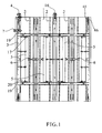
- the shuttering curved walls to which this invention relates comprises multiple panels joined together by means of clamps each of which can be curved as shown in Figure 1 , comprising the laminar element which can be shaped into a curve -1- and various beams -2- of special cross-section which will be described below attached equidistantly to laminar element -1-, with the arrangement being supplemented by beams -3- for each of the edges located to the left and right of the panel illustrated respectively.
- the various panels -1- may be connected vertically through clamps -4- and horizontally through clamps -7- as will be explained in greater detail below.
- An essential feature of the adjustable panel for shuttering according to this invention is synchronisation of the adjustment of the radius of curvature of element - 1- through aligning the adjustment elements along the generatrices of the panel in order to avoid warping of the latter with loss of parallelism between generatrices.
- This is achieved through the provision of shafts -5- parallel to the panel beams with one located between each two beams as illustrated in Figure 1 .
- These longitudinal shafts -5- can be rotated through the action of adjustable length arms -6- which are housed in one of beams -2- and act directly on two adjacent longitudinal shafts -5-, and through the articulations which will be explained the latter act on the side walls of the adjacent beams.
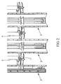
- each arm -6- which is adjustable for length has an external structure that is preferably hexagonal prismatic as this corresponds to a commercially-available section and has internal openings - 8- and -9- threaded in opposite directions in which threaded rods -10- and -11- are respectively housed in such a way that rotation of arm -6-, for example by means of a spanner from the exterior, brings about inward or outward movement of the respective housings for threaded rods -10- and -11- in mutually opposing directions.
- These rods are articulated through their ends -12- and -13- to corresponding extensions of shafts -5- which are indicated by number -14- and which may be double or single.
- Arm -6- is fixed with the ability to rotate in one of beams -2-, for example, through the arrangement illustrated in Figures 3 , 7 and 9 through collar -15- and the corresponding groove, although it should be understood that this could be achieved through any other type of assembly incorporating an enclosing bushing, bearing, etc.
- the slotted openings are in the form of an arc of a circle centered on the inside face of the shuttering panel, so that the length of the arc of circumference between two generatrices is maintained constant throughout the range of adjustment.
- connection between shafts -5- and beams -2- is similar to that described for the top through connecting rods -20- which are not shown at the top, together with wings -19- and transverse bars -17-.
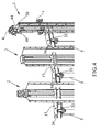
- the synchronisation shafts can rotate about their own geometrical axes or preferably they may be arranged as crankshafts as illustrated in the figures, preferably in Figures 4 , 9 and 12 .
- shafts -5- are mounted in the form of a crankshaft through wings -34- articulated through vertical pivots -35- which give rise to an eccentrically rotating shaft.
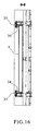
- Mounting a shaft -5- in the form of a crankshaft is also illustrated in Figure 15 and in the cross-section in Figure 16 , and it will be seen that the arrangement is the same at the top and the bottom.
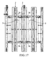
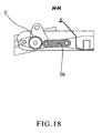
- Figures 17 and 18 show the articulation between one of synchronisation shafts -5- and adjacent beam -2- through intermediate connecting rods -36- in such a way that rotation of the said synchronisation shafts is transmitted to said adjacent beams -2-.
- Beams -2- have a special structure which can be seen especially in Figures 6 to 9 and 12 .
- the said beams have a central column with a prismatic or similar structure which imparts great rigidity to the beam and that in the situation illustrated in the figures they comprise a pentagonal prismatic structure with side faces -25- and - 26- substantially perpendicular to laminar shuttering element -1- and another two faces -27- and -28- which are inclined with respect to side faces -25- and -26- and a further face -29- perpendicular to said side faces -25- and -26- and substantially parallel to laminar element -1-.
- the beam is supplemented by two oblique wings -30- and -31-secured to laminar shuttering element -1- by means of flanges and bolts.
- the said columns strengthening the beams are provided with openings for clamps or other types of access such as upper longitudinal openings -32- and "tightening eye” openings -33- and others of the like.
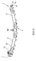
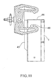
- Figures 13 and 14 show details of the construction of side beam -3- of the open type which has straight faces, giving rise to a general prismatic structure which on its front face has a longitudinal opening -46- for the insertion of one of the jaws of a clamp providing a vertical joint between an adjustable wall panel and another located at the top as will be seen in the detail in Figure 11 .
- the front face of beam -3- has a longitudinal abutment -45-designed to limit the transverse position of the clamp so that the arms thereof do not interfere internally with beam -3-.
- the beam has a stepped plate -37-joined by flanges -38- and -39- on its edges, preferably by laser welding, to the front face of beam -3- and the edge -40- of side face -47- of beam -3- respectively.
- On the edge of the other side -48- of the beam there is a second flange -41- of structure similar to that of flange -39-, and through this arrangement laminar shuttering element -1- is attached by means of bolts -42- as will be seen in Figure 14 .
- the beam is attached to laminar shuttering element -1- partly through bolts -42- mentioned which attach flange -41- and partly through long transverse bolts -43- which pass through the beam and are incorporated in the front face of shuttering element -1-through a widening head -50- which is flush with the said panel.
- Bolts -43- are fixed by nuts -49- which like bolts -42- can be accessed from the interior of the shuttering, allowing easy access to the said bolts for the purposes of maintaining the panel, dismantling laminar element -1-after use one or more times in construction, replacing it by a new laminar element, or for other tasks. It should also be borne in mind that the fact that the bolts are accessible from the rear face of the shuttering panel doubly eases the work of dismantling, because the fouling brought about by pouring of the concrete is very much reduced on this side.
- a top plug -44- seals off the column comprising doubly stepped internal plate -37- and the walls of beam -3-directly opposite the same.
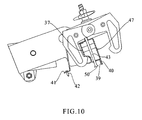
- Figure 10 shows the arrangement of a clamp for coupling two shuttering panels by their lateral edges, only one of these corresponding to beam -3- being shown in Figures 13 and 14 .
- the clamp fixes a panel to the adjacent panel by bringing together its jaws on the stepped internal plates -37- incorporated within beams -3-.
Landscapes
- Engineering & Computer Science (AREA)
- Architecture (AREA)
- Mechanical Engineering (AREA)
- Civil Engineering (AREA)
- Structural Engineering (AREA)
- Forms Removed On Construction Sites Or Auxiliary Members Thereof (AREA)
- Moulds, Cores, Or Mandrels (AREA)
- Joining Of Building Structures In Genera (AREA)
Claims (14)
- Verstellbare Platte zur Verschalung von gekrümmten Wänden in der Bauart, umfassend eine flächige Schaltafel (1), die gekrümmt werden kann, um die Oberfläche der Verschalung zu definieren, wobei diese flächige Tafel an einer ihrer Flächen mit mehreren vertikal angeordneten Trägern (2) verbunden ist, die die Struktur eines im Wesentlichen offenen trapezförmigen Gehäuses haben, wobei die Platte an ihren Kanten für die Befestigung an angrenzenden Platten auch Träger (3) aufweist, dadurch gekennzeichnet, dass die Anordnung von Schäften (5) zum Bewirken und Synchronisieren der Einstellung der Krümmung von dem flächigen Schalelement zwischen jedem der Plattenträger (2) parallel dazu ist, wobei jedes Paar benachbarter Schäfte (5) mit einem einzigen Betätigungsmechanismus verbunden ist, der mit dem Zwischenträger zwischen den benachbarten Schäften (5) verbunden ist, wobei der Mechanismus die zwei Schäfte (5), die daran angrenzen, veranlassen kann zu rotieren, wobei die besagten Betätigungs- und Synchronisierungsschäfte (5) mit den entsprechenden angrenzenden Trägern (2,3) durch gelenkige Verbindungsstangen (24) verbunden sind, um ihre relative Position und dadurch die Krümmung der Platte zu verändern.
- Verstellbare Platte zur Verschalung von gekrümmten Wänden nach Anspruch 1, dadurch gekennzeichnet, dass die Träger (2), die den Betätigungsmechanismus für die zwei angrenzenden Schäfte (2,3) tragen, oben und unten fixierte Querstäbe (17) aufweisen, welche Schäfte tragen, die in Bezug auf jene, die sie mit den Betätigungsschäften, die die Einstellung der Krümmung von den Platten synchronisieren, verbinden, exzentrisch sind, was durch Verbindungsarme erreicht wird, wobei die besagten Querstangen (17) auch schlitzförmige Öffnungen (18) aufweisen, um die Gelenke, die in Verlängerungen (19) fixiert sind, welche mit den angrenzenden Trägern (2,3) eine integrale Einheit bilden, zu führen.
- Verstellbare Platte zur Verschalung von gekrümmten Wänden nach Anspruch 2, gekennzeichnet durch die Anordnung von zwei Gelenken in jeder integralen Verlängerung (19) der Träger (2,3), die innerhalb der entsprechenden Schlitze (18) gleiten und ferner das Ende der Schwenkpositionen bestimmen.
- Verstellbare Platte zur Verschalung von gekrümmten Wänden nach Anspruch 2, dadurch gekennzeichnet, dass das Zentrum der Krümmung von den Schlitzen (18) auf der inneren Fläche der Schalplatte (1) liegt.
- Verstellbare Platte zur Verschalung von gekrümmten Wänden nach Anspruch 1, dadurch gekennzeichnet, dass die Schäfte (5), die die Einstellung der Krümmung von dem flächigen Schalelement (1) synchronisieren, die Form von Kurbelwellen annehmen, die oben und unten gelenkig an Flügeln (34) angebracht sind, welche an den Trägern, an denen der Betätigungsmechanismus montiert ist, fixiert sind.
- Verstellbare Platte zur Verschalung von gekrümmten Wänden nach Anspruch 1, dadurch gekennzeichnet, dass der einzige Betätigungsmechanismus für jeweils zwei der in Längsrichtung verlaufenden Synchronisierungsschäfte einen Querschaft (6) mit der Fähigkeit die Länge anzupassen umfasst, der in einem der Plattenträger (2) montiert ist und mit den zwei Synchronisierungsschäften (5), die an den besagten Träger (2) angrenzen, gelenkig verbunden ist.
- Verstellbare Platte zur Verschalung von gekrümmten Wänden nach Anspruch 6, dadurch gekennzeichnet, dass der Schaft (6), der in der Länge angepasst werden kann, einen zentralen getreckten Körper umfasst, der an seiner äußeren Oberfläche mit flachen Flächen und Gewindeöffnungen versehen ist, die sich zu jedem seiner Enden hin öffnen, wobei die Gewinde in entgegengesetzter Richtung verlaufen, und mit Stangen (10,11) verbunden sind, die gelenkig mit den angrenzenden Synchronisierungsschäften (5) verbunden sind, sodass die Rotation des zentralen Körpers des besagen Schafts (6) in eine Verlängerung oder Verkürzung der Distanz zwischen den Punkten der gelenkigen Verbindung mit den Synchronisierungsschäften und die entsprechende Veränderung in eine Krümmung der Schalplatte umwandelt wird.
- Verstellbare Platte zur Verschalung von gekrümmten Wänden nach Anspruch 2, dadurch gekennzeichnet, dass die Schlitzöffnungen (18) eine derartige Form haben, dass die Länge des Bogenumfangs zwischen zwei Generatices über den gesamten Einstellbereich konstant gehalten wird.
- Verstellbare Platte zur Verschalung von gekrümmten Wänden nach Anspruch 1, dadurch gekennzeichnet, dass die Träger (3) der Platte in ihren oberen und unteren Enden Fenster (46) mit innenliegenden Querstreben (49) für die Befestigung von Verbindungsklemmen (4) mit anderen Platten und Aufhängehaken zur Handhabung der Platten aufweisen.
- Verstellbare Platte zur Verschalung von gekrümmten Wänden nach Anspruch 1, dadurch gekennzeichnet, dass die Platte (1) an jeder ihrer lateralen Kanten Träger (3) in der Form eines offenen Gehäuses mit flachen Seiten aufweist, wobei eine davon in einem gefalteten Flansch (41) mündet, der an die innenliegende Fläche des flachen Schalbauteils angepasst und daran mit Bolzen (42) befestigt werden kann, die von der Innenseite der Platte zugänglich sind, während die gegenüberliegende laterale Fläche des Trägers durch seine Kante an einen Flansch (39) von einer Stufenplatte (37) fixiert ist, die innen in dem Träger enthalten ist, wobei er den gestuften Teil bildet, der die Kupplungsklemme (7) für zwei angrenzende Schalplatten über ihre lateralen Kanten hält.
- Verstellbare Platte zur Verschalung von gekrümmten Wänden nach Anspruch 10, dadurch gekennzeichnet, dass jeder der lateralen Endträger (3) einer Platte eine Öffnung (46) auf seiner vorderen Fläche gegenüber dem flächigen Schalelement (1), das parallel zu dem Schaft des Trägers ist, und eine innenliegende Querstrebe (49) aufweist, die fest mit dem Träger selbst verbunden ist, sodass einer der Backen einer Klemme (4), die dazu gedacht ist, die Schalplatte an einer weiteren, darüber liegenden Schalplatte zu fixieren, eingeführt und gesichert werden kann.
- Verstellbare Platte zur Verschalung von gekrümmten Wänden nach Anspruch 11, dadurch gekennzeichnet, dass die Querstrebe (49), die die Klemme (4) sichert, einen Stift umfasst, der mit dem Träger durch Verscheißen verbunden ist.
- Verstellbare Platte zur Verschalung von gekrümmten Wänden nach Anspruch 10, dadurch gekennzeichnet, dass die Verbindung zwischen dem Träger (3) und dem flächigen Schalelement (1) mittels Schrauben (42) bewirkt wird, die einen lateralen Flansch (41), der an einer der beiden Seiten des Trägers ist, direkt an dem besagten flächigen Schalelement (1) halten, wobei der Kopf von der Innenseite der Platte und auch mittels eines langen Stifts (43) zugänglich ist, der durch das laterale Schalelement (1) hindurch läuft, wobei sein Kopf (50) mit der äußeren Oberfläche davon bündig ist, und mittels einer Mutter auf der vorderen Fläche des Trägers (3) gesichert wird, die von der Innenseite der Schalplatte zugänglich ist.
- Verstellbare Platte zur Verschalung von gekrümmten Wänden nach Anspruch 13, dadurch gekennzeichnet, dass die Flansche (38,39) der Verstärkungsplatte (37) mit dem Träger (3) mittels Linearstitching unter Verwendung von Laserstrahlen verbunden sind.
Priority Applications (1)
| Application Number | Priority Date | Filing Date | Title |
|---|---|---|---|
| PL10380073T PL2292873T3 (pl) | 2009-07-15 | 2010-05-27 | Regulowany panel do szalowania ścian zakrzywionych |
Applications Claiming Priority (1)
| Application Number | Priority Date | Filing Date | Title |
|---|---|---|---|
| ES200930463A ES2335732B8 (es) | 2009-07-15 | 2009-07-15 | Panel ajustable para el encofrado de muros curvos |
Publications (2)
| Publication Number | Publication Date |
|---|---|
| EP2292873A1 EP2292873A1 (de) | 2011-03-09 |
| EP2292873B1 true EP2292873B1 (de) | 2014-06-04 |
Family
ID=42026603
Family Applications (1)
| Application Number | Title | Priority Date | Filing Date |
|---|---|---|---|
| EP10380073.6A Active EP2292873B1 (de) | 2009-07-15 | 2010-05-27 | Justierbares Paneel zum Umschalen von gewölbten Wänden |
Country Status (6)
| Country | Link |
|---|---|
| EP (1) | EP2292873B1 (de) |
| BR (1) | BRPI1002112B1 (de) |
| ES (2) | ES2335732B8 (de) |
| MX (1) | MX2010006123A (de) |
| PL (1) | PL2292873T3 (de) |
| UA (1) | UA98687C2 (de) |
Families Citing this family (7)
| Publication number | Priority date | Publication date | Assignee | Title |
|---|---|---|---|---|
| DE102010063032B4 (de) * | 2010-07-16 | 2012-04-05 | Doka Industrie Gmbh | Vorrichtung zum biegesteifen Verbinden von Schalungselementen |
| CN112343250B (zh) * | 2020-10-27 | 2022-04-01 | 深圳市榕大建设工程有限公司 | 一种eps模块化稳固搭建的节能建筑 |
| CN112854751B (zh) * | 2021-03-15 | 2022-06-21 | 山西三建集团有限公司 | 倒阶梯外凸形女儿墙顶部浇筑模板支撑体系的支拆方法 |
| CN114197780A (zh) * | 2021-12-10 | 2022-03-18 | 潘瑞瑞 | 一种室内绿色建筑墙板 |
| CN114407490B (zh) * | 2022-03-01 | 2024-03-22 | 秦皇岛博誉诺科技有限公司 | 一种层压机用柔性上箱 |
| CN117803853A (zh) * | 2024-02-18 | 2024-04-02 | 中国人民解放军海军特色医学中心 | 一种应急呼吸减压气瓶组 |
| CN120401781B (zh) * | 2025-07-01 | 2025-10-17 | 中交建筑集团有限公司 | 一种可调式背楞圆弧模板结构 |
Family Cites Families (7)
| Publication number | Priority date | Publication date | Assignee | Title |
|---|---|---|---|---|
| GB2133826B (en) * | 1983-01-11 | 1986-01-29 | Acrow | Adjusting curvative of formwork |
| DE4116439C1 (de) * | 1991-05-18 | 1992-08-27 | Maier G Paschal Werk | |
| DE9410525U1 (de) * | 1994-06-29 | 1994-08-18 | NOE-Schaltechnik Georg Meyer-Keller GmbH + Co, 73079 Süßen | Schalungselement für Rundschalungen zur Herstellung runder Wände aus Beton |
| ES2301490T3 (es) * | 2000-09-18 | 2008-07-01 | Ulma C Y E, S. Coop. | Sistema de encofrado modular de curvatura variable. |
| DE10240372B4 (de) * | 2002-09-02 | 2004-09-02 | Paschal-Werk G. Maier Gmbh | Rundschalung |
| DE10358886B4 (de) * | 2003-12-16 | 2012-06-06 | Peri Gmbh | Betonrundschalung |
| BE1017175A3 (nl) * | 2006-08-01 | 2008-03-04 | All Bast Nv | Inrichting voor het maken van een gebogen bekisting. |
-
2009
- 2009-07-15 ES ES200930463A patent/ES2335732B8/es not_active Expired - Fee Related
-
2010
- 2010-05-27 PL PL10380073T patent/PL2292873T3/pl unknown
- 2010-05-27 ES ES10380073.6T patent/ES2495347T3/es active Active
- 2010-05-27 EP EP10380073.6A patent/EP2292873B1/de active Active
- 2010-06-03 MX MX2010006123A patent/MX2010006123A/es active IP Right Grant
- 2010-06-24 BR BRPI1002112A patent/BRPI1002112B1/pt active IP Right Grant
- 2010-07-14 UA UAA201008792A patent/UA98687C2/ru unknown
Also Published As
| Publication number | Publication date |
|---|---|
| UA98687C2 (ru) | 2012-06-11 |
| PL2292873T3 (pl) | 2014-11-28 |
| ES2335732A1 (es) | 2010-03-31 |
| BRPI1002112B1 (pt) | 2019-08-27 |
| ES2335732B8 (es) | 2012-08-01 |
| EP2292873A1 (de) | 2011-03-09 |
| MX2010006123A (es) | 2011-01-24 |
| BRPI1002112A2 (pt) | 2011-07-05 |
| ES2495347T3 (es) | 2014-09-17 |
| ES2335732B1 (es) | 2010-10-13 |
Similar Documents
| Publication | Publication Date | Title |
|---|---|---|
| EP2292873B1 (de) | Justierbares Paneel zum Umschalen von gewölbten Wänden | |
| US20080193204A1 (en) | Adjustable Clamp for Securing Shuttering Panels | |
| JP2020511605A (ja) | コンクリート製品を製造するための型枠 | |
| EP1870535A1 (de) | Klemme zur sicherung von schalungstafeln | |
| KR20170095010A (ko) | 시공오차 보정이 용이한 모듈 건축의 접합구조 | |
| CN111733704B (zh) | 一种钢结构桥梁桁架安装施工方法 | |
| JP2004360378A (ja) | 型枠支持機構及び打設方法 | |
| JP6340645B1 (ja) | スプライスプレート保持用治具 | |
| CN113250382B (zh) | 一种箱型预制梁钢筋骨架内模板安装定位装置 | |
| CN222228013U (zh) | 一种钢筋笼调节装置 | |
| JP2006312869A (ja) | 型枠支持機構及び打設方法 | |
| KR102139015B1 (ko) | 프리스트레스트 콘크리트 거더용 강가로보 | |
| CN113756208A (zh) | 一种桥梁工程用支撑托架及其施工方法 | |
| CN217400107U (zh) | 一种箱型预制梁钢筋骨架内模板安装定位装置 | |
| CN117226383A (zh) | 一种钢型材安装定位辅助夹具 | |
| CN215484876U (zh) | 螺栓球网架的连接杆更换辅助架 | |
| CN114346118A (zh) | 一种建筑装配用的偏移矫正连接结构 | |
| EP2848593B1 (de) | Formhaltersystem für eine hohlglaswarenformmaschine | |
| AU2022275975A1 (en) | Framework support | |
| CN221390748U (zh) | 一种用于箱形柱拼装的辅助结构 | |
| CN216097070U (zh) | 一种用于钢箱梁u形肋焊接装置 | |
| CN219465226U (zh) | 一种沙发钢架焊接用治具 | |
| CN119160347B (zh) | 一种型材固定支撑装置 | |
| CN220599240U (zh) | 轻钢厂房变截面梁组拼工装 | |
| JP7745608B2 (ja) | 建築用ターンバックル |
Legal Events
| Date | Code | Title | Description |
|---|---|---|---|
| PUAI | Public reference made under article 153(3) epc to a published international application that has entered the european phase |
Free format text: ORIGINAL CODE: 0009012 |
|
| AK | Designated contracting states |
Kind code of ref document: A1 Designated state(s): AL AT BE BG CH CY CZ DE DK EE ES FI FR GB GR HR HU IE IS IT LI LT LU LV MC MK MT NL NO PL PT RO SE SI SK SM TR |
|
| AX | Request for extension of the european patent |
Extension state: BA ME RS |
|
| 17P | Request for examination filed |
Effective date: 20110321 |
|
| GRAP | Despatch of communication of intention to grant a patent |
Free format text: ORIGINAL CODE: EPIDOSNIGR1 |
|
| INTG | Intention to grant announced |
Effective date: 20131220 |
|
| INTG | Intention to grant announced |
Effective date: 20140107 |
|
| GRAS | Grant fee paid |
Free format text: ORIGINAL CODE: EPIDOSNIGR3 |
|
| GRAA | (expected) grant |
Free format text: ORIGINAL CODE: 0009210 |
|
| AK | Designated contracting states |
Kind code of ref document: B1 Designated state(s): AL AT BE BG CH CY CZ DE DK EE ES FI FR GB GR HR HU IE IS IT LI LT LU LV MC MK MT NL NO PL PT RO SE SI SK SM TR |
|
| REG | Reference to a national code |
Ref country code: GB Ref legal event code: FG4D |
|
| REG | Reference to a national code |
Ref country code: CH Ref legal event code: EP |
|
| REG | Reference to a national code |
Ref country code: AT Ref legal event code: REF Ref document number: 671209 Country of ref document: AT Kind code of ref document: T Effective date: 20140615 |
|
| REG | Reference to a national code |
Ref country code: IE Ref legal event code: FG4D |
|
| REG | Reference to a national code |
Ref country code: DE Ref legal event code: R096 Ref document number: 602010016420 Country of ref document: DE Effective date: 20140717 |
|
| REG | Reference to a national code |
Ref country code: ES Ref legal event code: FG2A Ref document number: 2495347 Country of ref document: ES Kind code of ref document: T3 Effective date: 20140917 |
|
| REG | Reference to a national code |
Ref country code: AT Ref legal event code: MK05 Ref document number: 671209 Country of ref document: AT Kind code of ref document: T Effective date: 20140604 |
|
| REG | Reference to a national code |
Ref country code: NL Ref legal event code: VDEP Effective date: 20140604 |
|
| PG25 | Lapsed in a contracting state [announced via postgrant information from national office to epo] |
Ref country code: CY Free format text: LAPSE BECAUSE OF FAILURE TO SUBMIT A TRANSLATION OF THE DESCRIPTION OR TO PAY THE FEE WITHIN THE PRESCRIBED TIME-LIMIT Effective date: 20140604 Ref country code: FI Free format text: LAPSE BECAUSE OF FAILURE TO SUBMIT A TRANSLATION OF THE DESCRIPTION OR TO PAY THE FEE WITHIN THE PRESCRIBED TIME-LIMIT Effective date: 20140604 Ref country code: NO Free format text: LAPSE BECAUSE OF FAILURE TO SUBMIT A TRANSLATION OF THE DESCRIPTION OR TO PAY THE FEE WITHIN THE PRESCRIBED TIME-LIMIT Effective date: 20140904 Ref country code: LT Free format text: LAPSE BECAUSE OF FAILURE TO SUBMIT A TRANSLATION OF THE DESCRIPTION OR TO PAY THE FEE WITHIN THE PRESCRIBED TIME-LIMIT Effective date: 20140604 Ref country code: GR Free format text: LAPSE BECAUSE OF FAILURE TO SUBMIT A TRANSLATION OF THE DESCRIPTION OR TO PAY THE FEE WITHIN THE PRESCRIBED TIME-LIMIT Effective date: 20140905 |
|
| REG | Reference to a national code |
Ref country code: LT Ref legal event code: MG4D |
|
| PG25 | Lapsed in a contracting state [announced via postgrant information from national office to epo] |
Ref country code: LV Free format text: LAPSE BECAUSE OF FAILURE TO SUBMIT A TRANSLATION OF THE DESCRIPTION OR TO PAY THE FEE WITHIN THE PRESCRIBED TIME-LIMIT Effective date: 20140604 Ref country code: HR Free format text: LAPSE BECAUSE OF FAILURE TO SUBMIT A TRANSLATION OF THE DESCRIPTION OR TO PAY THE FEE WITHIN THE PRESCRIBED TIME-LIMIT Effective date: 20140604 Ref country code: AT Free format text: LAPSE BECAUSE OF FAILURE TO SUBMIT A TRANSLATION OF THE DESCRIPTION OR TO PAY THE FEE WITHIN THE PRESCRIBED TIME-LIMIT Effective date: 20140604 Ref country code: SE Free format text: LAPSE BECAUSE OF FAILURE TO SUBMIT A TRANSLATION OF THE DESCRIPTION OR TO PAY THE FEE WITHIN THE PRESCRIBED TIME-LIMIT Effective date: 20140604 |
|
| REG | Reference to a national code |
Ref country code: PL Ref legal event code: T3 |
|
| PG25 | Lapsed in a contracting state [announced via postgrant information from national office to epo] |
Ref country code: RO Free format text: LAPSE BECAUSE OF FAILURE TO SUBMIT A TRANSLATION OF THE DESCRIPTION OR TO PAY THE FEE WITHIN THE PRESCRIBED TIME-LIMIT Effective date: 20140604 Ref country code: EE Free format text: LAPSE BECAUSE OF FAILURE TO SUBMIT A TRANSLATION OF THE DESCRIPTION OR TO PAY THE FEE WITHIN THE PRESCRIBED TIME-LIMIT Effective date: 20140604 Ref country code: CZ Free format text: LAPSE BECAUSE OF FAILURE TO SUBMIT A TRANSLATION OF THE DESCRIPTION OR TO PAY THE FEE WITHIN THE PRESCRIBED TIME-LIMIT Effective date: 20140604 Ref country code: PT Free format text: LAPSE BECAUSE OF FAILURE TO SUBMIT A TRANSLATION OF THE DESCRIPTION OR TO PAY THE FEE WITHIN THE PRESCRIBED TIME-LIMIT Effective date: 20141006 Ref country code: SK Free format text: LAPSE BECAUSE OF FAILURE TO SUBMIT A TRANSLATION OF THE DESCRIPTION OR TO PAY THE FEE WITHIN THE PRESCRIBED TIME-LIMIT Effective date: 20140604 |
|
| PG25 | Lapsed in a contracting state [announced via postgrant information from national office to epo] |
Ref country code: IS Free format text: LAPSE BECAUSE OF FAILURE TO SUBMIT A TRANSLATION OF THE DESCRIPTION OR TO PAY THE FEE WITHIN THE PRESCRIBED TIME-LIMIT Effective date: 20141004 Ref country code: NL Free format text: LAPSE BECAUSE OF FAILURE TO SUBMIT A TRANSLATION OF THE DESCRIPTION OR TO PAY THE FEE WITHIN THE PRESCRIBED TIME-LIMIT Effective date: 20140604 |
|
| REG | Reference to a national code |
Ref country code: DE Ref legal event code: R097 Ref document number: 602010016420 Country of ref document: DE |
|
| PLBE | No opposition filed within time limit |
Free format text: ORIGINAL CODE: 0009261 |
|
| STAA | Information on the status of an ep patent application or granted ep patent |
Free format text: STATUS: NO OPPOSITION FILED WITHIN TIME LIMIT |
|
| PG25 | Lapsed in a contracting state [announced via postgrant information from national office to epo] |
Ref country code: IT Free format text: LAPSE BECAUSE OF FAILURE TO SUBMIT A TRANSLATION OF THE DESCRIPTION OR TO PAY THE FEE WITHIN THE PRESCRIBED TIME-LIMIT Effective date: 20140604 Ref country code: DK Free format text: LAPSE BECAUSE OF FAILURE TO SUBMIT A TRANSLATION OF THE DESCRIPTION OR TO PAY THE FEE WITHIN THE PRESCRIBED TIME-LIMIT Effective date: 20140604 |
|
| 26N | No opposition filed |
Effective date: 20150305 |
|
| REG | Reference to a national code |
Ref country code: DE Ref legal event code: R097 Ref document number: 602010016420 Country of ref document: DE Effective date: 20150305 |
|
| PG25 | Lapsed in a contracting state [announced via postgrant information from national office to epo] |
Ref country code: BE Free format text: LAPSE BECAUSE OF FAILURE TO SUBMIT A TRANSLATION OF THE DESCRIPTION OR TO PAY THE FEE WITHIN THE PRESCRIBED TIME-LIMIT Effective date: 20140604 |
|
| PG25 | Lapsed in a contracting state [announced via postgrant information from national office to epo] |
Ref country code: SI Free format text: LAPSE BECAUSE OF FAILURE TO SUBMIT A TRANSLATION OF THE DESCRIPTION OR TO PAY THE FEE WITHIN THE PRESCRIBED TIME-LIMIT Effective date: 20140604 |
|
| REG | Reference to a national code |
Ref country code: DE Ref legal event code: R119 Ref document number: 602010016420 Country of ref document: DE |
|
| REG | Reference to a national code |
Ref country code: CH Ref legal event code: PL |
|
| GBPC | Gb: european patent ceased through non-payment of renewal fee |
Effective date: 20150527 |
|
| PG25 | Lapsed in a contracting state [announced via postgrant information from national office to epo] |
Ref country code: LI Free format text: LAPSE BECAUSE OF NON-PAYMENT OF DUE FEES Effective date: 20150531 Ref country code: MC Free format text: LAPSE BECAUSE OF FAILURE TO SUBMIT A TRANSLATION OF THE DESCRIPTION OR TO PAY THE FEE WITHIN THE PRESCRIBED TIME-LIMIT Effective date: 20140604 Ref country code: LU Free format text: LAPSE BECAUSE OF FAILURE TO SUBMIT A TRANSLATION OF THE DESCRIPTION OR TO PAY THE FEE WITHIN THE PRESCRIBED TIME-LIMIT Effective date: 20150527 Ref country code: CH Free format text: LAPSE BECAUSE OF NON-PAYMENT OF DUE FEES Effective date: 20150531 |
|
| REG | Reference to a national code |
Ref country code: IE Ref legal event code: MM4A |
|
| REG | Reference to a national code |
Ref country code: FR Ref legal event code: ST Effective date: 20160129 |
|
| PG25 | Lapsed in a contracting state [announced via postgrant information from national office to epo] |
Ref country code: DE Free format text: LAPSE BECAUSE OF NON-PAYMENT OF DUE FEES Effective date: 20151201 Ref country code: GB Free format text: LAPSE BECAUSE OF NON-PAYMENT OF DUE FEES Effective date: 20150527 Ref country code: IE Free format text: LAPSE BECAUSE OF NON-PAYMENT OF DUE FEES Effective date: 20150527 |
|
| PG25 | Lapsed in a contracting state [announced via postgrant information from national office to epo] |
Ref country code: FR Free format text: LAPSE BECAUSE OF NON-PAYMENT OF DUE FEES Effective date: 20150601 |
|
| PG25 | Lapsed in a contracting state [announced via postgrant information from national office to epo] |
Ref country code: MT Free format text: LAPSE BECAUSE OF FAILURE TO SUBMIT A TRANSLATION OF THE DESCRIPTION OR TO PAY THE FEE WITHIN THE PRESCRIBED TIME-LIMIT Effective date: 20140604 |
|
| PG25 | Lapsed in a contracting state [announced via postgrant information from national office to epo] |
Ref country code: SM Free format text: LAPSE BECAUSE OF FAILURE TO SUBMIT A TRANSLATION OF THE DESCRIPTION OR TO PAY THE FEE WITHIN THE PRESCRIBED TIME-LIMIT Effective date: 20140604 Ref country code: HU Free format text: LAPSE BECAUSE OF FAILURE TO SUBMIT A TRANSLATION OF THE DESCRIPTION OR TO PAY THE FEE WITHIN THE PRESCRIBED TIME-LIMIT; INVALID AB INITIO Effective date: 20100527 Ref country code: BG Free format text: LAPSE BECAUSE OF FAILURE TO SUBMIT A TRANSLATION OF THE DESCRIPTION OR TO PAY THE FEE WITHIN THE PRESCRIBED TIME-LIMIT Effective date: 20140604 |
|
| PG25 | Lapsed in a contracting state [announced via postgrant information from national office to epo] |
Ref country code: TR Free format text: LAPSE BECAUSE OF FAILURE TO SUBMIT A TRANSLATION OF THE DESCRIPTION OR TO PAY THE FEE WITHIN THE PRESCRIBED TIME-LIMIT Effective date: 20140604 |
|
| PG25 | Lapsed in a contracting state [announced via postgrant information from national office to epo] |
Ref country code: MK Free format text: LAPSE BECAUSE OF FAILURE TO SUBMIT A TRANSLATION OF THE DESCRIPTION OR TO PAY THE FEE WITHIN THE PRESCRIBED TIME-LIMIT Effective date: 20140604 |
|
| PG25 | Lapsed in a contracting state [announced via postgrant information from national office to epo] |
Ref country code: AL Free format text: LAPSE BECAUSE OF FAILURE TO SUBMIT A TRANSLATION OF THE DESCRIPTION OR TO PAY THE FEE WITHIN THE PRESCRIBED TIME-LIMIT Effective date: 20140604 |
|
| PGFP | Annual fee paid to national office [announced via postgrant information from national office to epo] |
Ref country code: PL Payment date: 20250307 Year of fee payment: 16 |
|
| PGFP | Annual fee paid to national office [announced via postgrant information from national office to epo] |
Ref country code: ES Payment date: 20250602 Year of fee payment: 16 |