EP2290480B1 - Pièce d'horlogerie à dispositif de sonnerie munie d'un timbre - Google Patents
Pièce d'horlogerie à dispositif de sonnerie munie d'un timbre Download PDFInfo
- Publication number
- EP2290480B1 EP2290480B1 EP09168727A EP09168727A EP2290480B1 EP 2290480 B1 EP2290480 B1 EP 2290480B1 EP 09168727 A EP09168727 A EP 09168727A EP 09168727 A EP09168727 A EP 09168727A EP 2290480 B1 EP2290480 B1 EP 2290480B1
- Authority
- EP
- European Patent Office
- Prior art keywords
- gong
- watch
- hammer
- stamp
- plane
- Prior art date
- Legal status (The legal status is an assumption and is not a legal conclusion. Google has not performed a legal analysis and makes no representation as to the accuracy of the status listed.)
- Active
Links
- 230000007246 mechanism Effects 0.000 title claims description 4
- 230000003213 activating effect Effects 0.000 claims 2
- 230000036961 partial effect Effects 0.000 description 5
- 238000006073 displacement reaction Methods 0.000 description 4
- 238000012550 audit Methods 0.000 description 2
- 230000005540 biological transmission Effects 0.000 description 2
- 230000003247 decreasing effect Effects 0.000 description 2
- 238000009527 percussion Methods 0.000 description 2
- BASFCYQUMIYNBI-UHFFFAOYSA-N platinum Chemical compound [Pt] BASFCYQUMIYNBI-UHFFFAOYSA-N 0.000 description 2
- 230000003595 spectral effect Effects 0.000 description 2
- 238000004804 winding Methods 0.000 description 2
- 235000020303 café frappé Nutrition 0.000 description 1
- 230000006835 compression Effects 0.000 description 1
- 238000007906 compression Methods 0.000 description 1
- 230000001419 dependent effect Effects 0.000 description 1
- 238000004519 manufacturing process Methods 0.000 description 1
- 239000000463 material Substances 0.000 description 1
- 239000007769 metal material Substances 0.000 description 1
- 230000000704 physical effect Effects 0.000 description 1
- 229910000679 solder Inorganic materials 0.000 description 1
- 238000001228 spectrum Methods 0.000 description 1
Images

Classifications
-
- G—PHYSICS
- G04—HOROLOGY
- G04B—MECHANICALLY-DRIVEN CLOCKS OR WATCHES; MECHANICAL PARTS OF CLOCKS OR WATCHES IN GENERAL; TIME PIECES USING THE POSITION OF THE SUN, MOON OR STARS
- G04B21/00—Indicating the time by acoustic means
- G04B21/02—Regular striking mechanisms giving the full hour, half hour or quarter hour
- G04B21/06—Details of striking mechanisms, e.g. hammer, fan governor
-
- G—PHYSICS
- G04—HOROLOGY
- G04B—MECHANICALLY-DRIVEN CLOCKS OR WATCHES; MECHANICAL PARTS OF CLOCKS OR WATCHES IN GENERAL; TIME PIECES USING THE POSITION OF THE SUN, MOON OR STARS
- G04B23/00—Arrangements producing acoustic signals at preselected times
- G04B23/02—Alarm clocks
- G04B23/026—Hammer driving; hammers; devices with several hammers or sounding bodies; vibrators
Definitions
- the invention relates to ringtones, and in particular watches with mechanical ringtones including a stamp struck by a hammer to generate vibrations.
- the stamp used is a circular-shaped wire placed in a plane parallel to the dial of the watch.
- the wire is arranged around a movement, in the cage of the watch.
- One end of the stamp is fixed, for example by solder, to a stamp holder.
- the other end of the stamp is usually free.
- the stamp holder is itself secured to the watch plate and holds the wire above the plate.
- the watch includes a hammer actuated at predetermined times.
- the vibration of the stamp is produced by the impact of the hammer near the stamp holder.
- the hammer makes a rotation in the plane of the stamp so as to vibrate the stamp in its plan. Part of the vibration of the timbre is transmitted to the deck.
- the stage then vibrates in a plane parallel to the plane of the timbre.
- the resulting vibration is composed of several eigenfrequencies, whose number and intensity, especially in the audible range, depend on the geometry of the timbre and the physical properties of the material.
- fundamental frequency which is also called first harmonic
- harmonics which are integer multiples of the fundamental frequency.
- the frequencies above the fundamental are no longer integer multiples of the lowest frequency, they are rather defined by partial ones.
- the ring volume is relatively limited and the energy efficiency of the ring is relatively low.
- the sound quality of the ring is generally poor because of a small number of eigenfrequencies of the sound emitted.
- a striking mechanism which consists of a hammer rotatably mounted about an axis of rotation perpendicular to a base plate, to strike a bell fixed on the base plate.
- a striking mechanism which consists of a hammer rotatably mounted about an axis of rotation perpendicular to a base plate, to strike a bell fixed on the base plate.
- the invention aims to solve one or more of these disadvantages.
- An advantage of the watch according to the invention lies in the fact that the hammer is arranged to strike said stamp in another direction than in the direction of the plane of the stamp, that is to say with an inclined incidence relative to said plan.
- the invention proposes a watch provided with a ring tone.
- the timbre surrounds a movement of the watch and extends substantially in a plane.
- a hammer hits the stamp to make it vibrate.
- the hammer hits the stamp with an inclined bearing in relation to this plane.
- this stamp thus vibrates according to the normal to its plan.
- the energy efficiency of the stamp is thus improved.
- the transmission of vibrations to the watch plate is improved, the stamp holder can normally transmit to the plate tensile forces / compression. This further improves the energetic efficiency of the patch and can improve the spectral density of the ring generated, in particular by decreasing it, which makes it possible to reduce a dissonance due to near frequency partials.
- the number of partials, generated for the ring is notably increased.
- the figure 1 is a top view of the interior of a watch 1 according to one embodiment of the invention, when the hammer is in the rest position.
- the figure 2 is a side sectional view according to AA of the watch details of the figure 1 .
- the watch 1 comprises a plate 8.
- a cage is formed in the middle part of this plate 8.
- the watch 1 comprises a movement (not illustrated) known per se and housed in the cage of the plate 8. The movement will typically be a movement mechanical.
- the watch 1 comprises a stamp 2 and a stamp holder 3 also housed in the cage.
- the stamp holder 3 is integral with the plate 8.
- the stamp holder 3 is projecting relative to the bottom of the plate 8.
- the stamp 2 surrounds the movement and extends substantially in a plane x, y, plane which is substantially parallel to the plane of the dial of the watch 1.
- the stamp 2 is made in the form of a beam, circular in the illustrated example. This beam can for example be made in the form of a wire.
- the stamp 2 is fixed by one of its ends 22 to the stamp holder 3. The other end 21 of the stamp 2 is free.
- the stamp holder 3 maintains the stamp 2 above the bottom of the plate 8. A travel of the stamp 2 along the z axis is thus arranged so that it can vibrate in this direction.
- the watch 1 comprises a hammer 5 adapted to strike the stamp 2 when it is actuated.
- the hammer 5 comprises a striking face 53 intended to come into contact with the patch 2.
- the hammer 5 is in a rest position in which its striking face 53 is spaced from the stamp 2.
- the hammer 5 is pivotally mounted relative to an axis 51 parallel to the plane of the stamp 2, the axis having a direction Y in the illustrated example.
- the hammer 5 furthermore has an actuating face 52 substantially perpendicular to the striking face 53.
- the watch 1 comprises an actuating member 4 pivotally mounted relative to the plate 8.
- the actuating member 4 is pivotally mounted about a direction axis z, normal to the plane x, y.
- a leaf spring 6 recalls the hammer 5 towards its rest position, exerting a force tending to move the face 53 of the stamp 2 away.
- the leaf spring 6 has an end 61 fixed to the plate 8 and a free end 62 which urges the hammer 5.
- the free end 62 of the spring 6 urges an inner face of the hammer 5.
- a stop 7 limits the pivoting of the hammer 5 induced by the leaf spring 6 and defines its rest position.
- the actuating member 4 drives the hammer 5 from its position apart to its striking position at predefined times.
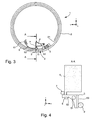
- the figures 3 and 4 represent the respective positions of the hammer 5 and the actuating member 4 in the striking position.
- the actuating member 4 has pivoted about its axis.
- the actuating member 4 has driven the hammer 5 by striking its face 52 in its rotational stroke.
- the hammer 5 has thus pivoted from its rest position to its striking position.
- the hammer 5 thus transforms a displacement of the member 4 in the plane x, y in displacement in particular along the z axis.
- the face 53 is then in contact with the stamp 2.
- the stamp 2 is then moved and generates a vibration.
- the actuating member 4 is then moved away from the face 52 and the spring 6 recalls the hammer 5 towards its rest position spaced from the stamp 2.
- the contact angle is substantially oriented along the z axis, and is therefore inclined with respect to the x plane, y of the stamp 2.
- the instantaneous speed of the hammer 5 is in fact oriented according to the z axis at the time of contact between the face 53 and the stamp 2.
- the stamp 2 is driven in a displacement having a component perpendicular to its plane x, y.
- the energy efficiency of the sound generation by the stamp 2 and the transmission of vibrations to the plate 8 via the stamp holder 3 are improved.
- the angle of incidence will be normal to this face 53 at the time of striking.
- the hammer 5 may in particular be actuated every minute.
- the actuating member 4 may in particular actuate the hammer 5 at regular intervals or at a predefined time.
- the stamp 2 is in this case formed of a circular beam, which reduces its size inside the watch.
- the beam will typically have a diameter of less than 1 mm, for example of the order of 0.6 mm.
- the illustrated beam forms a portion of torus. This torus portion will advantageously extend at an angle of between 300 ° and 350 °.
- the beam may also have other suitable shapes, for example a rectangular shape, for acoustic reasons.
- the stamp 2 may in particular be made of a metallic material. In order to increase the amplitude the displacement of the stamp 2, the zone on which the hammer 5 hits will advantageously be placed at a distance from the binding between the stamp 2 and the stamp holder 3.
- the stamp 2 has a single end attached to the stamp holder 3.
- the invention also applies to a watch having several stamp-holders to which the same stamp is attached, or to a watch in which the stamp is attached to the door-stamp other than by one of its extremities.
- the watch 1 has a single hammer 5.
- a watch according to the invention may have several hammers and the stamp may have several corresponding striking surfaces.
- the invention also applies to a stamp having several superposed windings.
- the invention can be applied to a wristwatch, but also to other types of timepieces, such as alarm clocks.
- the impact of the hammer 5 may be inclined relative to the normal z to said plane.
- twisting forces will be transmitted by the stamp holder 3 to the plate 8 of the watch. This further improves the energy efficiency of the patch 2 and can improve the spectral density of the ring generated, in particular by decreasing it, which makes it possible to reduce a dissonance due to the near-frequency partials.
Description
- L'invention concerne les sonneries de montre, et en particulier les montres munies de sonneries mécaniques comprenant un timbre heurté par un marteau pour générer des vibrations.
- Dans le domaine de l'horlogerie, une architecture traditionnelle est utilisée pour réaliser des mouvements, qui sont munis de mécanismes de sonnerie, tels que des répétitions minutes. Dans ces réalisations, le timbre utilisé est un fil métallique de forme circulaire placé dans un plan parallèle au cadran de la montre. Le fil métallique est disposé autour d'un mouvement, dans la cage de la montre. Une extrémité du timbre est fixée, par exemple par brasure, à un porte-timbre. L'autre extrémité du timbre est généralement libre. Le porte-timbre est lui-même solidaire de la platine de montre et maintient le fil métallique au-dessus de la platine. La montre comprend un marteau actionné à des moments prédéterminés. La vibration du timbre est produite par l'impact du marteau à proximité du porte-timbre. Le marteau effectue une rotation dans le plan du timbre de façon à faire vibrer le timbre dans son plan. Une partie de la vibration du timbre est transmise à la platine. La platine vibre alors dans un plan parallèle au plan du timbre.
- La vibration obtenue est composée de plusieurs fréquences propres, dont le nombre et l'intensité, en particulier dans le domaine audible, dépendent de la géométrie du timbre et des propriétés physiques du matériau. Généralement pour la production d'un son musical de hauteur fixe dans tout le spectre sonore, il y a une fréquence fondamentale, qui est appelée aussi premier harmonique, et un ou plusieurs harmoniques, qui sont des multiples entiers de la fréquence fondamentale. Dans d'autres cas où les fréquences supérieures à la fondamentale ne sont plus des multiples entiers de la fréquence la plus basse, on les définit plutôt par partiels. On rencontre principalement un son à plusieurs partiels dans des instruments à percussion ou certains instruments à cordes, ou lors de transitoires d'attaque, telles que le choc ou l'impact d'un marteau contre un timbre d'une sonnerie de montre.
- En pratique, le volume de sonnerie s'avère relativement limité et le rendement énergétique de la sonnerie est relativement faible. Par ailleurs la qualité sonore de la sonnerie reste généralement pauvre du fait d'un faible nombre de fréquences propres du son émis.
- Il existe également dans l'état de la technique une réalisation d'un mécanisme de sonnerie, qui est constitué d'un marteau monté rotatif autour d'un axe de rotation perpendiculaire à une plaque de base, pour venir frapper une cloche fixée sur la plaque de base. A ce titre, on peut citer le document de brevet
US 1,001,095 A . Cependant cette réalisation ne permet pas d'avoir un volume de sonnerie relativement élevé et une qualité sonore suffisante. - L'invention vise à résoudre un ou plusieurs de ces inconvénients.
- A cet effet, l'invention porte ainsi sur une montre incluant un dispositif de sonnerie comprenant:
- au moins un timbre entourant un mouvement et s'étendant sensiblement dans un plan,
- au moins un porte-timbre solidaire d'une platine de la montre, le timbre étant fixé sur le porte-timbre,
- au moins un marteau pour venir frapper le timbre afin de produire une vibration dudit timbre,
- Des formes d'exécution particulières de la montre sont définies dans les revendications dépendantes 2 à 9.
- Un avantage de la montre selon l'invention réside dans le fait que le marteau est agencé pour venir frapper ledit timbre dans une autre direction que dans la direction du plan du timbre, c'est-à-dire avec une incidence inclinée par rapport audit plan. Grâce à la frappe du marteau contre le timbre avec une incidence inclinée, le rendement de la sonnerie de montre est optimisé, car les vibrations sont générées plus efficacement vers les divers éléments de la montre.
- D'autres caractéristiques et avantages de l'invention ressortiront clairement de la description qui en est faite ci-après, à titre indicatif et nullement limitatif, en référence aux dessins annexés, dans lesquels :
- la
figure 1 est une vue de dessus d'un mode de réalisation d'une montre selon l'invention, dans laquelle le marteau est en position de repos; - la
figure 2 est une vue en coupe de côté selon A-A de détails de la montre de lafigure 1 ; - la
figure 3 est une vue de dessus du mode de réalisation de lafigure 1 , dans laquelle le marteau est en position de frappe; et - la
figure 4 est une vue en coupe de côté selon A-A de détails de la montre de lafigure 3 . - L'invention propose une montre munie d'un timbre de sonnerie. Le timbre entoure un mouvement de la montre et s'étend sensiblement dans un plan. Un marteau vient frapper le timbre afin de le faire vibrer. Le marteau vient frapper le timbre avec une incidence inclinée par rapport à ce plan.
- Lors d'une percussion du timbre par le marteau, ce timbre vibre ainsi selon la normale à son plan. Le rendement énergétique du timbre est ainsi amélioré. Par ailleurs, la transmission des vibrations à la platine de la montre est améliorée, le porte-timbre pouvant normalement transmettre à la platine des efforts de traction/compression. Cela améliore encore le rendement énergétique du timbre et peut améliorer la densité spectrale de la sonnerie générée notamment en la diminuant, ce qui permet de diminuer une dissonance due aux partiels proches en fréquence. Le nombre de partiels, générés pour la sonnerie, est notamment accru.
- La
figure 1 est une vue de dessus de l'intérieur d'une montre 1 selon un mode de réalisation de l'invention, lorsque le marteau est en position de repos. Lafigure 2 est une vue en coupe de côté selon A-A de détails de la montre de lafigure 1 . La montre 1 comprend une platine 8. Une cage est ménagée dans la partie médiane de cette platine 8. La montre 1 comprend un mouvement (non illustré) connu en soi et logé dans la cage de la platine 8. Le mouvement sera typiquement un mouvement mécanique. - La montre 1 comprend un timbre 2 et un porte-timbre 3 également logés dans la cage. Le porte-timbre 3 est solidaire de la platine 8. Le porte-timbre 3 est en saillie par rapport au fond de la platine 8. Le timbre 2 entoure le mouvement et s'étend sensiblement dans un plan x, y, plan qui est sensiblement parallèle au plan du cadran de la montre 1.
- Le timbre 2 est réalisé sous forme de poutre, circulaire dans l'exemple illustré. Cette poutre peut par exemple être réalisée sous la forme d'un fil métallique. Le timbre 2 est fixé par une de ses extrémités 22 au porte-timbre 3. L'autre extrémité 21 du timbre 2 est libre. Le porte-timbre 3 maintient le timbre 2 au-dessus du fond de la platine 8. Un débattement du timbre 2 selon l'axe z est ainsi ménagé pour que celui-ci puisse vibrer selon cette direction.
- La montre 1 comprend un marteau 5 apte à venir frapper le timbre 2 lorsqu'il est actionné. Le marteau 5 comprend une face de frappe 53, destinée à entrer en contact avec le timbre 2. Sur les
figures 1 et 2 , le marteau 5 est dans une position au repos dans laquelle sa face de frappe 53 est écartée du timbre 2. Le marteau 5 est monté pivotant par rapport à un axe 51 parallèle au plan du timbre 2, l'axe ayant une direction Y dans l'exemple illustré. Le marteau 5 présente de plus une face d'actionnement 52 sensiblement perpendiculaire à la face de frappe 53. - La montre 1 comprend un organe d'actionnement 4 monté pivotant par rapport à la platine 8. L'organe d'actionnement 4 est monté pivotant autour d'un axe de direction z, normal au plan x, y.
- Un ressort à lame 6 rappelle le marteau 5 vers sa position au repos, en exerçant un effort tendant à écarter la face 53 du timbre 2. Le ressort à lame 6 présente une extrémité 61 fixée à la platine 8 et une extrémité libre 62 sollicitant le marteau 5. L'extrémité libre 62 du ressort 6 sollicite une face intérieure du marteau 5. Une butée 7 limite le pivotement du marteau 5 induit par le ressort à lame 6 et définit sa position de repos.
- L'organe d'actionnement 4 entraîne le marteau 5 de sa position écartée vers sa position de frappe à des instants prédéfinis. Les
figures 3 et 4 représentent les positions respectives du marteau 5 et de l'organe d'actionnement 4 dans la position de frappe. - Sur ces figures, l'organe d'actionnement 4 a pivoté autour de son axe. L'organe d'actionnement 4 a entraîné le marteau 5 en heurtant sa face 52 dans sa course de rotation. Le marteau 5 a ainsi pivoté de sa position de repos vers sa position de frappe. Le marteau 5 transforme ainsi un déplacement de l'organe 4 dans le plan x, y en déplacement notamment selon l'axe z. La face 53 est alors en contact avec le timbre 2. Le timbre 2 est alors déplacé et génère une vibration. L'organe d'actionnement 4 est ensuite éloigné de la face 52 et le ressort 6 rappelle le marteau 5 vers sa position de repos écartée du timbre 2.
- Lorsque la face 53 frappe le timbre 2, l'incidence de contact est sensiblement orientée selon l'axe z, et est donc inclinée par rapport au plan x, y du timbre 2. La vitesse instantanée du marteau 5 est en effet orientée selon l'axe z au moment du contact entre la face 53 et le timbre 2. Ainsi, le timbre 2 est entraîné selon un déplacement présentant une composante perpendiculaire à son plan x, y. Le rendement énergétique de la génération sonore par le timbre 2 ainsi que la transmission des vibrations à la platine 8 par l'intermédiaire du porte-timbre 3 sont améliorés. Pour une face 53 plate, l'angle d'incidence sera la normale à cette face 53 au moment de la frappe.
- Le marteau 5 pourra notamment être actionné toutes les minutes. L'organe d'actionnement 4 pourra notamment actionner le marteau 5 à intervalles réguliers ou à un horaire prédéfini.
- Le timbre 2 est en l'occurrence formé d'une poutre de forme circulaire, ce qui permet de réduire son encombrement à l'intérieur de la montre. La poutre présentera typiquement un diamètre inférieur à 1 mm, par exemple de l'ordre de 0.6 mm. La poutre illustrée forme une portion de tore. Cette portion de tore s'étendra avantageusement selon un angle compris entre 300° et 350°. Cependant, la poutre pourra également présenter d'autres formes appropriées, par exemple une forme rectangulaire, pour des raisons acoustiques. Le timbre 2 peut être notamment réalisé dans un matériau métallique. Afin d'accroître l'amplitude du déplacement du timbre 2, la zone sur laquelle le marteau 5 vient frapper sera avantageusement placée à distance de la fixation entre le timbre 2 et le porte-timbre 3.
- Dans l'exemple illustré, le timbre 2 présente une seule extrémité fixée au porte-timbre 3. L'invention s'applique cependant également à une montre présentant plusieurs portes-timbres auxquels un même timbre est fixé, ou à une montre dans laquelle le timbre est fixé au porte-timbre autrement que par une de ses extrémités. Dans l'exemple illustré, la montre 1 présente un unique marteau 5. Cependant, une montre selon l'invention pourra présenter plusieurs marteaux et le timbre pourra présenter plusieurs surfaces de frappe correspondantes. Bien qu'on ait illustré un timbre à un seul enroulement, l'invention s'applique également à un timbre présentant plusieurs enroulements superposés.
- L'invention pourra s'appliquer à une montre-bracelet, mais également à d'autres types de pièces d'horlogerie, telles que des réveils.
- Bien que cela ne soit pas illustré, l'incidence du marteau 5 pourra être inclinée par rapport à la normale z audit plan. Ainsi, des efforts de torsion seront transmis par le porte-timbre 3 à la platine 8 de la montre. Cela améliore encore le rendement énergétique du timbre 2 et peut améliorer la densité spectrale de la sonnerie générée notamment en la diminuant, ce qui permet de diminuer une dissonance due au partiels proches en fréquence.
Claims (9)
- Montre (1) incluant un dispositif de sonnerie comprenant:- au moins un timbre (2) entourant un mouvement et s'étendant sensiblement dans un plan (x, y),- au moins un porte-timbre (3) solidaire d'une platine (8) de la montre, le timbre étant fixé sur le porte-timbre,- au moins un marteau (5) pour venir frapper le timbre (2) afin de produire une vibration dudit timbre,caractérisée en ce que le marteau (5) est monté à rotation par rapport à la platine autour d'un axe parallèle audit plan (x, y) pour venir frapper le timbre avec une incidence inclinée par rapport audit plan.
- Montre selon la revendication 1, comprenant un organe d'actionnement (4) agencé pour être commandé à un horaire prédéfini pour entraîner le marteau (5) depuis sa position écartée vers sa position de frappe.
- Montre selon la revendication 2, comprenant un ressort de rappel (6) sollicitant le marteau (5) vers sa position écartée.
- Montre selon la revendication 2 ou 3, dans lequel l'organe d'actionnement (4) est monté à rotation autour d'un axe (z) normal audit plan (x, y) et est agencé pour être entraîné rotation à l'horaire prédéfini selon une course durant laquelle il heurte le marteau (5).
- Montre selon l'une des revendications précédentes, dans laquelle le timbre (2) présente une poutre allongée entourant le mécanisme.
- Montre selon la revendication 5, dans laquelle ladite poutre forme un cercle ou un rectangle.
- Montre selon l'une des revendications précédentes, dans laquelle une cage logeant le mouvement est ménagée, et dans laquelle le timbre (2) est disposé dans la cage.
- Montre selon l'une des revendications précédentes, dans laquelle le timbre (2) est fixé au porte-timbre (3) par au moins une seule de ses extrémités (22).
- Montre selon l'une des revendications précédentes, dans laquelle le timbre (2) est en saillie par rapport à un fond de la platine (8), et dans laquelle le timbre (2) est disposé au-dessus du fond de la platine (8).
Priority Applications (6)
| Application Number | Priority Date | Filing Date | Title |
|---|---|---|---|
| EP09168727A EP2290480B1 (fr) | 2009-08-26 | 2009-08-26 | Pièce d'horlogerie à dispositif de sonnerie munie d'un timbre |
| AT09168727T ATE555426T1 (de) | 2009-08-26 | 2009-08-26 | Glocke für ein schlagwerk einer uhr |
| US12/868,951 US8395970B2 (en) | 2009-08-26 | 2010-08-26 | Timepiece with a striking work fitted with a gong |
| JP2010189334A JP5149350B2 (ja) | 2009-08-26 | 2010-08-26 | ゴングが嵌め込まれた時打ち機構付きの時計 |
| CN2010102651719A CN102004434B (zh) | 2009-08-26 | 2010-08-26 | 包括装配有音簧的打点机件的钟表 |
| HK11109688.5A HK1155524A1 (en) | 2009-08-26 | 2011-09-14 | Timepiece with a striking work fitted with a gong |
Applications Claiming Priority (1)
| Application Number | Priority Date | Filing Date | Title |
|---|---|---|---|
| EP09168727A EP2290480B1 (fr) | 2009-08-26 | 2009-08-26 | Pièce d'horlogerie à dispositif de sonnerie munie d'un timbre |
Publications (2)
| Publication Number | Publication Date |
|---|---|
| EP2290480A1 EP2290480A1 (fr) | 2011-03-02 |
| EP2290480B1 true EP2290480B1 (fr) | 2012-04-25 |
Family
ID=41571600
Family Applications (1)
| Application Number | Title | Priority Date | Filing Date |
|---|---|---|---|
| EP09168727A Active EP2290480B1 (fr) | 2009-08-26 | 2009-08-26 | Pièce d'horlogerie à dispositif de sonnerie munie d'un timbre |
Country Status (6)
| Country | Link |
|---|---|
| US (1) | US8395970B2 (fr) |
| EP (1) | EP2290480B1 (fr) |
| JP (1) | JP5149350B2 (fr) |
| CN (1) | CN102004434B (fr) |
| AT (1) | ATE555426T1 (fr) |
| HK (1) | HK1155524A1 (fr) |
Families Citing this family (9)
| Publication number | Priority date | Publication date | Assignee | Title |
|---|---|---|---|---|
| EP2290479B1 (fr) * | 2009-08-26 | 2013-11-13 | Montres Breguet SA | Timbre pour une sonnerie d'une pièce d'horlogerie |
| CH707876B1 (fr) * | 2013-04-11 | 2017-05-31 | Feldbausch & Cie Ag | Pièce d'horlogerie comportant un dispositif de sonnerie. |
| EP2808745B1 (fr) * | 2013-05-28 | 2019-07-03 | Montres Breguet SA | Mécanisme de sonnerie muni de moyens de sélection de mode vibratoire d'un timbre |
| DE102014114969B3 (de) * | 2014-10-15 | 2015-04-23 | Lange Uhren Gmbh | Uhr |
| CH711475B1 (fr) * | 2015-08-31 | 2019-09-30 | Blancpain Sa | Pièce d'horlogerie à sonnerie. |
| AU201610483S (en) * | 2016-02-01 | 2016-09-30 | Knog Pty Ltd | Bell |
| EP3663869B1 (fr) * | 2018-12-06 | 2021-06-16 | Montres Breguet S.A. | Mecanisme de sonnerie d'horlogerie a marteau suspendu |
| EP3885843A1 (fr) * | 2020-03-24 | 2021-09-29 | The Swatch Group Research and Development Ltd | Montre à mouvement mécanique ou électronique pourvue d'un mécanisme de sonnerie |
| EP4105733A1 (fr) * | 2021-06-15 | 2022-12-21 | Montres Breguet S.A. | Mécanisme de sonnerie a percussion, notamment pour l'horlogerie |
Family Cites Families (9)
| Publication number | Priority date | Publication date | Assignee | Title |
|---|---|---|---|---|
| CH45807A (fr) * | 1908-11-27 | 1909-12-16 | Wittnauer & Co | Sonnerie pour mouvements d'horlogerie |
| US1001095A (en) * | 1910-04-28 | 1911-08-22 | Charles O Truscott | Clock striking mechanism. |
| DE443387C (de) * | 1926-06-12 | 1927-04-27 | Hans Benecke | Sperrvorrichtung fuer das Schlagwerk von Zimmeruhren |
| FR2480453A1 (fr) * | 1980-04-10 | 1981-10-16 | Odo | Systeme de sonnerie mecanique debrayable |
| EP1394637B1 (fr) * | 2002-08-27 | 2006-04-26 | Frédéric Piguet S.A. | Pièce d'horlogerie telle que montre-bracelet comprenant un mécanisme de réveil |
| ATE395639T1 (de) * | 2005-03-31 | 2008-05-15 | Zenith Internat Sa | Repetieruhr mit einem minutenrepetiermechanismus |
| ATE430955T1 (de) * | 2006-09-26 | 2009-05-15 | Montres Breguet Sa | Uhr mit schlagwerk |
| JP5206233B2 (ja) * | 2007-09-05 | 2013-06-12 | セイコーエプソン株式会社 | 時計および携帯機器 |
| EP2290479B1 (fr) * | 2009-08-26 | 2013-11-13 | Montres Breguet SA | Timbre pour une sonnerie d'une pièce d'horlogerie |
-
2009
- 2009-08-26 EP EP09168727A patent/EP2290480B1/fr active Active
- 2009-08-26 AT AT09168727T patent/ATE555426T1/de active
-
2010
- 2010-08-26 JP JP2010189334A patent/JP5149350B2/ja active Active
- 2010-08-26 CN CN2010102651719A patent/CN102004434B/zh active Active
- 2010-08-26 US US12/868,951 patent/US8395970B2/en active Active
-
2011
- 2011-09-14 HK HK11109688.5A patent/HK1155524A1/xx unknown
Also Published As
| Publication number | Publication date |
|---|---|
| CN102004434A (zh) | 2011-04-06 |
| JP2011047945A (ja) | 2011-03-10 |
| US20110051567A1 (en) | 2011-03-03 |
| ATE555426T1 (de) | 2012-05-15 |
| CN102004434B (zh) | 2013-04-17 |
| EP2290480A1 (fr) | 2011-03-02 |
| US8395970B2 (en) | 2013-03-12 |
| HK1155524A1 (en) | 2012-05-18 |
| JP5149350B2 (ja) | 2013-02-20 |
Similar Documents
| Publication | Publication Date | Title |
|---|---|---|
| EP2290480B1 (fr) | Pièce d'horlogerie à dispositif de sonnerie munie d'un timbre | |
| EP1906267B1 (fr) | Montre à sonnerie | |
| EP2339412B1 (fr) | Mécanisme de sonnerie d'une montre | |
| EP2107437B1 (fr) | Timbre pour une sonnerie ou alarme d'une montre | |
| EP2290479B1 (fr) | Timbre pour une sonnerie d'une pièce d'horlogerie | |
| EP2707779B1 (fr) | Pièce d'horlogerie à mécanisme sonore | |
| EP2367078A1 (fr) | Montre à sonnerie munie d'une membrane acoustique | |
| EP2463731B1 (fr) | Mécanisme de sonnerie d'une montre | |
| EP2196869B1 (fr) | Boîte de montre à dispositif de sonnerie | |
| EP2485097A2 (fr) | Mécanisme de sonnerie d'une montre à blocage du marteau | |
| EP3540526B1 (fr) | Mécanisme de sonnerie d'horlogerie | |
| EP2362279B1 (fr) | Mécanisme de sonnerie d'une montre à contre-ressort amortisseur actif | |
| EP1760549A1 (fr) | Timbre pour mécanisme de sonnerie de pièce d'horlogerie | |
| CH702145A1 (fr) | Timbre pour une sonnerie d'une piece d'horlogerie. | |
| CH701699A2 (fr) | Piece d'horlogerie a dispositif de sonnerie munie d'un timbre. | |
| EP3657269A1 (fr) | Organe resonant pour un mecanisme de sonnerie d'une montre ou d'une boite a musique | |
| CH699894A2 (fr) | Mécanisme de sonnerie avec un timbre déplacé et lâché. | |
| EP3696618A1 (fr) | Montre a sonnerie ou musicale avec agencement pour guider des ondes acoustiques | |
| CH701698A2 (fr) | Timbre pour une sonnerie d'une piece d'horlogerie. | |
| EP3070541A1 (fr) | Montre à sonnerie munie d'un agencement particulier de frappe d'un timbre | |
| CH710899A2 (fr) | Montre à sonnerie munie d'un agencement particulier de frappe d'un timbre | |
| CH715841B1 (fr) | Montre à sonnerie ou musicale avec agencement pour guider des ondes acoustiques. | |
| CH714752A2 (fr) | Mécanisme de sonnerie d'horloge. | |
| CH718282A2 (fr) | Timbre à section variable pour une montre à sonnerie, et ensemble de timbres. | |
| EP3835883A1 (fr) | Agencement de maintien et transmission vibratoire d'une membrane de rayonnement acoustique dans une boîte de montre |
Legal Events
| Date | Code | Title | Description |
|---|---|---|---|
| PUAI | Public reference made under article 153(3) epc to a published international application that has entered the european phase |
Free format text: ORIGINAL CODE: 0009012 |
|
| AK | Designated contracting states |
Kind code of ref document: A1 Designated state(s): AT BE BG CH CY CZ DE DK EE ES FI FR GB GR HR HU IE IS IT LI LT LU LV MC MK MT NL NO PL PT RO SE SI SK SM TR |
|
| 17P | Request for examination filed |
Effective date: 20110902 |
|
| GRAP | Despatch of communication of intention to grant a patent |
Free format text: ORIGINAL CODE: EPIDOSNIGR1 |
|
| GRAS | Grant fee paid |
Free format text: ORIGINAL CODE: EPIDOSNIGR3 |
|
| GRAA | (expected) grant |
Free format text: ORIGINAL CODE: 0009210 |
|
| AK | Designated contracting states |
Kind code of ref document: B1 Designated state(s): AT BE BG CH CY CZ DE DK EE ES FI FR GB GR HR HU IE IS IT LI LT LU LV MC MK MT NL NO PL PT RO SE SI SK SM TR |
|
| REG | Reference to a national code |
Ref country code: GB Ref legal event code: FG4D Free format text: NOT ENGLISH |
|
| REG | Reference to a national code |
Ref country code: CH Ref legal event code: EP Ref country code: CH Ref legal event code: NV Representative=s name: ICB INGENIEURS CONSEILS EN BREVETS SA |
|
| REG | Reference to a national code |
Ref country code: AT Ref legal event code: REF Ref document number: 555426 Country of ref document: AT Kind code of ref document: T Effective date: 20120515 |
|
| REG | Reference to a national code |
Ref country code: IE Ref legal event code: FG4D Free format text: LANGUAGE OF EP DOCUMENT: FRENCH |
|
| REG | Reference to a national code |
Ref country code: DE Ref legal event code: R096 Ref document number: 602009006499 Country of ref document: DE Effective date: 20120621 |
|
| REG | Reference to a national code |
Ref country code: NL Ref legal event code: VDEP Effective date: 20120425 |
|
| REG | Reference to a national code |
Ref country code: AT Ref legal event code: MK05 Ref document number: 555426 Country of ref document: AT Kind code of ref document: T Effective date: 20120425 |
|
| LTIE | Lt: invalidation of european patent or patent extension |
Effective date: 20120425 |
|
| PG25 | Lapsed in a contracting state [announced via postgrant information from national office to epo] |
Ref country code: IS Free format text: LAPSE BECAUSE OF FAILURE TO SUBMIT A TRANSLATION OF THE DESCRIPTION OR TO PAY THE FEE WITHIN THE PRESCRIBED TIME-LIMIT Effective date: 20120825 Ref country code: FI Free format text: LAPSE BECAUSE OF FAILURE TO SUBMIT A TRANSLATION OF THE DESCRIPTION OR TO PAY THE FEE WITHIN THE PRESCRIBED TIME-LIMIT Effective date: 20120425 Ref country code: SE Free format text: LAPSE BECAUSE OF FAILURE TO SUBMIT A TRANSLATION OF THE DESCRIPTION OR TO PAY THE FEE WITHIN THE PRESCRIBED TIME-LIMIT Effective date: 20120425 Ref country code: CY Free format text: LAPSE BECAUSE OF FAILURE TO SUBMIT A TRANSLATION OF THE DESCRIPTION OR TO PAY THE FEE WITHIN THE PRESCRIBED TIME-LIMIT Effective date: 20120425 Ref country code: LT Free format text: LAPSE BECAUSE OF FAILURE TO SUBMIT A TRANSLATION OF THE DESCRIPTION OR TO PAY THE FEE WITHIN THE PRESCRIBED TIME-LIMIT Effective date: 20120425 Ref country code: NO Free format text: LAPSE BECAUSE OF FAILURE TO SUBMIT A TRANSLATION OF THE DESCRIPTION OR TO PAY THE FEE WITHIN THE PRESCRIBED TIME-LIMIT Effective date: 20120725 Ref country code: PL Free format text: LAPSE BECAUSE OF FAILURE TO SUBMIT A TRANSLATION OF THE DESCRIPTION OR TO PAY THE FEE WITHIN THE PRESCRIBED TIME-LIMIT Effective date: 20120425 |
|
| PG25 | Lapsed in a contracting state [announced via postgrant information from national office to epo] |
Ref country code: HR Free format text: LAPSE BECAUSE OF FAILURE TO SUBMIT A TRANSLATION OF THE DESCRIPTION OR TO PAY THE FEE WITHIN THE PRESCRIBED TIME-LIMIT Effective date: 20120425 Ref country code: PT Free format text: LAPSE BECAUSE OF FAILURE TO SUBMIT A TRANSLATION OF THE DESCRIPTION OR TO PAY THE FEE WITHIN THE PRESCRIBED TIME-LIMIT Effective date: 20120827 Ref country code: SI Free format text: LAPSE BECAUSE OF FAILURE TO SUBMIT A TRANSLATION OF THE DESCRIPTION OR TO PAY THE FEE WITHIN THE PRESCRIBED TIME-LIMIT Effective date: 20120425 Ref country code: LV Free format text: LAPSE BECAUSE OF FAILURE TO SUBMIT A TRANSLATION OF THE DESCRIPTION OR TO PAY THE FEE WITHIN THE PRESCRIBED TIME-LIMIT Effective date: 20120425 Ref country code: GR Free format text: LAPSE BECAUSE OF FAILURE TO SUBMIT A TRANSLATION OF THE DESCRIPTION OR TO PAY THE FEE WITHIN THE PRESCRIBED TIME-LIMIT Effective date: 20120726 |
|
| PG25 | Lapsed in a contracting state [announced via postgrant information from national office to epo] |
Ref country code: DK Free format text: LAPSE BECAUSE OF FAILURE TO SUBMIT A TRANSLATION OF THE DESCRIPTION OR TO PAY THE FEE WITHIN THE PRESCRIBED TIME-LIMIT Effective date: 20120425 Ref country code: SK Free format text: LAPSE BECAUSE OF FAILURE TO SUBMIT A TRANSLATION OF THE DESCRIPTION OR TO PAY THE FEE WITHIN THE PRESCRIBED TIME-LIMIT Effective date: 20120425 Ref country code: NL Free format text: LAPSE BECAUSE OF FAILURE TO SUBMIT A TRANSLATION OF THE DESCRIPTION OR TO PAY THE FEE WITHIN THE PRESCRIBED TIME-LIMIT Effective date: 20120425 Ref country code: RO Free format text: LAPSE BECAUSE OF FAILURE TO SUBMIT A TRANSLATION OF THE DESCRIPTION OR TO PAY THE FEE WITHIN THE PRESCRIBED TIME-LIMIT Effective date: 20120425 Ref country code: CZ Free format text: LAPSE BECAUSE OF FAILURE TO SUBMIT A TRANSLATION OF THE DESCRIPTION OR TO PAY THE FEE WITHIN THE PRESCRIBED TIME-LIMIT Effective date: 20120425 Ref country code: AT Free format text: LAPSE BECAUSE OF FAILURE TO SUBMIT A TRANSLATION OF THE DESCRIPTION OR TO PAY THE FEE WITHIN THE PRESCRIBED TIME-LIMIT Effective date: 20120425 Ref country code: EE Free format text: LAPSE BECAUSE OF FAILURE TO SUBMIT A TRANSLATION OF THE DESCRIPTION OR TO PAY THE FEE WITHIN THE PRESCRIBED TIME-LIMIT Effective date: 20120425 |
|
| BERE | Be: lapsed |
Owner name: MONTRES BREGUET SA Effective date: 20120831 |
|
| PG25 | Lapsed in a contracting state [announced via postgrant information from national office to epo] |
Ref country code: IT Free format text: LAPSE BECAUSE OF FAILURE TO SUBMIT A TRANSLATION OF THE DESCRIPTION OR TO PAY THE FEE WITHIN THE PRESCRIBED TIME-LIMIT Effective date: 20120425 |
|
| PLBE | No opposition filed within time limit |
Free format text: ORIGINAL CODE: 0009261 |
|
| STAA | Information on the status of an ep patent application or granted ep patent |
Free format text: STATUS: NO OPPOSITION FILED WITHIN TIME LIMIT |
|
| PG25 | Lapsed in a contracting state [announced via postgrant information from national office to epo] |
Ref country code: MC Free format text: LAPSE BECAUSE OF NON-PAYMENT OF DUE FEES Effective date: 20120831 |
|
| 26N | No opposition filed |
Effective date: 20130128 |
|
| PG25 | Lapsed in a contracting state [announced via postgrant information from national office to epo] |
Ref country code: ES Free format text: LAPSE BECAUSE OF FAILURE TO SUBMIT A TRANSLATION OF THE DESCRIPTION OR TO PAY THE FEE WITHIN THE PRESCRIBED TIME-LIMIT Effective date: 20120805 |
|
| REG | Reference to a national code |
Ref country code: IE Ref legal event code: MM4A |
|
| REG | Reference to a national code |
Ref country code: DE Ref legal event code: R097 Ref document number: 602009006499 Country of ref document: DE Effective date: 20130128 |
|
| PG25 | Lapsed in a contracting state [announced via postgrant information from national office to epo] |
Ref country code: BE Free format text: LAPSE BECAUSE OF NON-PAYMENT OF DUE FEES Effective date: 20120831 |
|
| PG25 | Lapsed in a contracting state [announced via postgrant information from national office to epo] |
Ref country code: IE Free format text: LAPSE BECAUSE OF NON-PAYMENT OF DUE FEES Effective date: 20120826 Ref country code: BG Free format text: LAPSE BECAUSE OF FAILURE TO SUBMIT A TRANSLATION OF THE DESCRIPTION OR TO PAY THE FEE WITHIN THE PRESCRIBED TIME-LIMIT Effective date: 20120725 |
|
| PG25 | Lapsed in a contracting state [announced via postgrant information from national office to epo] |
Ref country code: MT Free format text: LAPSE BECAUSE OF FAILURE TO SUBMIT A TRANSLATION OF THE DESCRIPTION OR TO PAY THE FEE WITHIN THE PRESCRIBED TIME-LIMIT Effective date: 20120425 |
|
| PG25 | Lapsed in a contracting state [announced via postgrant information from national office to epo] |
Ref country code: TR Free format text: LAPSE BECAUSE OF FAILURE TO SUBMIT A TRANSLATION OF THE DESCRIPTION OR TO PAY THE FEE WITHIN THE PRESCRIBED TIME-LIMIT Effective date: 20120425 |
|
| PG25 | Lapsed in a contracting state [announced via postgrant information from national office to epo] |
Ref country code: LU Free format text: LAPSE BECAUSE OF NON-PAYMENT OF DUE FEES Effective date: 20120826 Ref country code: SM Free format text: LAPSE BECAUSE OF FAILURE TO SUBMIT A TRANSLATION OF THE DESCRIPTION OR TO PAY THE FEE WITHIN THE PRESCRIBED TIME-LIMIT Effective date: 20120425 |
|
| PG25 | Lapsed in a contracting state [announced via postgrant information from national office to epo] |
Ref country code: HU Free format text: LAPSE BECAUSE OF FAILURE TO SUBMIT A TRANSLATION OF THE DESCRIPTION OR TO PAY THE FEE WITHIN THE PRESCRIBED TIME-LIMIT Effective date: 20090826 |
|
| PG25 | Lapsed in a contracting state [announced via postgrant information from national office to epo] |
Ref country code: MK Free format text: LAPSE BECAUSE OF FAILURE TO SUBMIT A TRANSLATION OF THE DESCRIPTION OR TO PAY THE FEE WITHIN THE PRESCRIBED TIME-LIMIT Effective date: 20120425 |
|
| REG | Reference to a national code |
Ref country code: FR Ref legal event code: PLFP Year of fee payment: 8 |
|
| REG | Reference to a national code |
Ref country code: FR Ref legal event code: PLFP Year of fee payment: 9 |
|
| REG | Reference to a national code |
Ref country code: FR Ref legal event code: PLFP Year of fee payment: 10 |
|
| P01 | Opt-out of the competence of the unified patent court (upc) registered |
Effective date: 20230611 |
|
| PGFP | Annual fee paid to national office [announced via postgrant information from national office to epo] |
Ref country code: GB Payment date: 20230720 Year of fee payment: 15 Ref country code: CH Payment date: 20230902 Year of fee payment: 15 |
|
| PGFP | Annual fee paid to national office [announced via postgrant information from national office to epo] |
Ref country code: FR Payment date: 20230720 Year of fee payment: 15 Ref country code: DE Payment date: 20230720 Year of fee payment: 15 |