EP2288571B1 - Behandlungsmaschine für flaschen oder dergleichen behälter - Google Patents
Behandlungsmaschine für flaschen oder dergleichen behälter Download PDFInfo
- Publication number
- EP2288571B1 EP2288571B1 EP09745501.8A EP09745501A EP2288571B1 EP 2288571 B1 EP2288571 B1 EP 2288571B1 EP 09745501 A EP09745501 A EP 09745501A EP 2288571 B1 EP2288571 B1 EP 2288571B1
- Authority
- EP
- European Patent Office
- Prior art keywords
- rotor
- machine
- rollers
- processing
- processing machine
- Prior art date
- Legal status (The legal status is an assumption and is not a legal conclusion. Google has not performed a legal analysis and makes no representation as to the accuracy of the status listed.)
- Not-in-force
Links
Images


Classifications
-
- B—PERFORMING OPERATIONS; TRANSPORTING
- B67—OPENING, CLOSING OR CLEANING BOTTLES, JARS OR SIMILAR CONTAINERS; LIQUID HANDLING
- B67C—CLEANING, FILLING WITH LIQUIDS OR SEMILIQUIDS, OR EMPTYING, OF BOTTLES, JARS, CANS, CASKS, BARRELS, OR SIMILAR CONTAINERS, NOT OTHERWISE PROVIDED FOR; FUNNELS
- B67C3/00—Bottling liquids or semiliquids; Filling jars or cans with liquids or semiliquids using bottling or like apparatus; Filling casks or barrels with liquids or semiliquids
- B67C3/02—Bottling liquids or semiliquids; Filling jars or cans with liquids or semiliquids using bottling or like apparatus
- B67C3/22—Details
-
- B—PERFORMING OPERATIONS; TRANSPORTING
- B67—OPENING, CLOSING OR CLEANING BOTTLES, JARS OR SIMILAR CONTAINERS; LIQUID HANDLING
- B67C—CLEANING, FILLING WITH LIQUIDS OR SEMILIQUIDS, OR EMPTYING, OF BOTTLES, JARS, CANS, CASKS, BARRELS, OR SIMILAR CONTAINERS, NOT OTHERWISE PROVIDED FOR; FUNNELS
- B67C7/00—Concurrent cleaning, filling, and closing of bottles; Processes or devices for at least two of these operations
- B67C7/0006—Conveying; Synchronising
- B67C7/002—General lay-out of bottle-handling machines
-
- B—PERFORMING OPERATIONS; TRANSPORTING
- B67—OPENING, CLOSING OR CLEANING BOTTLES, JARS OR SIMILAR CONTAINERS; LIQUID HANDLING
- B67C—CLEANING, FILLING WITH LIQUIDS OR SEMILIQUIDS, OR EMPTYING, OF BOTTLES, JARS, CANS, CASKS, BARRELS, OR SIMILAR CONTAINERS, NOT OTHERWISE PROVIDED FOR; FUNNELS
- B67C7/00—Concurrent cleaning, filling, and closing of bottles; Processes or devices for at least two of these operations
- B67C7/0073—Sterilising, aseptic filling and closing
Definitions
- the invention relates to a treatment machine for bottles or similar containers with at least one rotatably mounted about a vertical machine axis and rotatably driven about this machine axis rotor and a plurality of treatment stations formed on the rotor according to the preamble of claim 1.
- Treatment machines of this type are known in various designs in particular as filling machines, labellers, inspection machines and rinsers.
- ball slewing rings are used, with which the rotor u.a. is rotatably mounted on the largest possible diameter to achieve the required stability.
- the disadvantage here is in particular that such ball slewing rings are expensive and often available on the market only with considerable delivery times.
- Airconditioning machines in the form of container filling machines ( DE 14 32 396 A1 ; US 1 992 329 ), which have the features of the preamble of claim 1 and in which the respective rotatable about a vertical axis of the machine rotor rotatably supported for an axial bearing with an annular track on a plurality of freely rotatably mounted on a machine frame rollers.
- a treatment machine in the form of a bottle filling machine ( DE 10 12 536 B ) With a likewise about a vertical machine axis circumferentially drivable rotor, which is supported axially via a ball slewing on the machine frame.
- a plurality of rollers abutting against an annular surface of the rotor are provided on the machine frame.
- the object of the invention is to show a container treatment machine, which can be realized with sufficient stability of the storage of the rotating rotor with a significantly reduced cost.
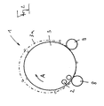
- the in the FIG. 1 Generally designated 1 container treatment machine is designed as a filling machine for filling containers in the form of bottles 2 with a liquid product or product.
- the container treatment machine 1 consists of a rotor 3 that can be driven around a vertical machine axis MA (arrow A), which is designed in the form of a ring with a rotor section 3.1 and a rotor section 3.2 and filling stations 4 are provided at its circumference or rotor section 3.1, each consisting of one Filling element 5 and a container carrier 6, on which the bottles 2 are oriented with their bottle axis oriented in the vertical direction on a muzzle flange hanging.
- Each filling element 5 is connected via a product line 7.1 with a ring boiler 7 on the rotor 3.
- the bottles 2 to be filled are fed to the filling stations 4 in each case via a container inlet formed by a circulating transport star 8.
- the filled bottles 2 are taken from the filling stations 4 on a transport star 9 forming the container outlet.
- the peculiarity of the treatment machine 1 is that the bearing of the rotor 3 takes place on a relatively large diameter, which corresponds to about 70% of the outer diameter in this embodiment, the rotor 3 has at its the filling elements 5 carrying section 3.1, with the help of rollers 10 and 11 on a stationary recording or on a stationary, ie with the rotor 3 non-rotating machine frame 12 are freely rotatably mounted.
- the machine frame 12 and the two bearings 8.1 and 9.1 are provided for the transport stars 8 and 9.
- rollers 10 and 11 are preferably arranged distributed at equal angular intervals around the machine axis, in this embodiment, the rollers 10 each freely rotatable about an axis radially to the machine axis MA and the rollers 11 each freely rotatable about axes parallel or approximately parallel to Machine axis MA.
- rollers 10 which act as a group or in its entirety as an axial support bearing for the rotor 3, are in each case against a formed on the underside of the rotor or the annular rotor section 3.2 bearing or tread 10.1, which surrounds the machine axis MA circular and is arranged in the illustrated embodiment in a plane perpendicular to the machine axis MA. With the tread 10.1, the rotor 3 thus supported on the rollers 10.
- rollers 10 and 11 are each individual rollers, ie rollers which are individually rotatably provided individually and spaced apart and are preferably adjustable, both in the vertical direction, as well as radially to the machine axis MA.
- the drive of the rotor 3 about the machine axis MA takes place in the illustrated embodiment via a shaft 13 which is driven in rotation by a drive of the container treatment machine 1, not shown.
- the particular advantage of the container treatment machine 1 is that the rotor 3 is axially and radially supported while avoiding an expensive ball slewing on a relatively large diameter, by an inexpensive and structurally simple Lageranordnüng of the rollers 10 and 11 and the associated bearing surfaces 10.1 and 11.1 is formed.
- the design of the bearing surfaces 10.1 and 11.1 on the rotor 3 has the advantage that this is usually made anyway as a turned part and it is therefore possible to produce in the manufacture of the rotor 3 at the same time the bearing surfaces 10.1 and 11.1 with the required precision.
- the exact spatial relationship between the treatment stations on the rotor and outer functional elements, such as the transport stars 8 and 9 is particularly in lightweight and / or suspended and transported containers or bottles 2, such as. PET or plastic bottles of great importance to ensure a reliable operation of the treatment machine 1 containing treatment or production line.
- the movable arrangement of the bearings of the rollers 11 outside the fixed portion allows compensation for changes in the rotor diameter, especially in thermal expansion caused by changes in the rotor diameter, the (changes) eg in a hot filling of products as well as in a cleaning and / or sterilization of Treatment machine 1 occur with a hot cleaning and / or sterilization medium.
- This compensation of temperature-related changes in the rotor diameter is achieved by radial displacement of the machine axis MA, as shown in the FIG. 2 is indicated by the broken line 3a.
- the fixed relative to the machine frame rollers 11 are arranged such that the tangent points between the rotor 3 and the transport stars 8.und 9 not even when occurring thermal expansions or relocate only to a reasonable extent.
- the fixed rollers 11 are arranged at the tangent points or in the vicinity thereof.
- the bearing surface 10.1 is formed for the rollers 10 so that the rotor 3 is reliably supported on the rollers 10 in each state with this bearing surface.
- rollers 10 and 11 are provided on the machine frame 12.
- the rollers 10 and 11 are also the possibility to store the rollers 10 and 11 of both groups of rollers on the rotor 3 and form the associated bearing or running surfaces on the machine frame 12.
- a group of rollers for example the rollers 10 on the machine frame 12 and the other group of rollers, for example the rollers 11 on the rotor 3.
- the bearings for the radial bearing causing rollers 11 may be partially fixed and partially movable provided, for the compensation described above with changes in the rotor diameter.
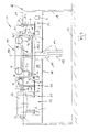
- FIG. 3 1 shows a treatment machine 1a, which is likewise designed as a filling machine and in turn has a plurality of treatment or filling stations 4, each with a filling element 5 and a container carrier 6, on the circumference of a rotor 16 that can be driven circumferentially about the vertical machine axis MA.
- the rotor 16 is mounted rotatably and suspended on an upper support plate 17 of a support frame 18 about the vertical machine axis MA, again with the rollers 10 and 11 distributed around the machine axis MA. These are in turn freely rotatably mounted on the upper side of the support plate 17 , about axes radially to the machine axis MA (rollers 10) and about axes parallel to the machine axis MA (rollers 11).
- the rotor 16 of this is at least with its filling stations 4 having part through an opening of the support plate 17 on the underside of this support plate. Due to the design of the bearing or running surfaces 10. 1 and 11. 1 on the rotor section 16. 3 projecting radially over the rotor section 16. 1, the rotor 16 is mounted with the bearing arrangement formed by the rollers 10 and 11 on a diameter which is greater than the outer diameter that the rotor 16 has at the filling station 4 having rotor portion 16.1.
- the rotor 16 is similar to the rotor 3 with a machine rotor MA concentrically enclosing annular rotor portion 16.1, on which the filling elements 5 are provided, as well as formed with a radially to the machine axis MA extending rotor portion 16.2.
- the rotor section 16.1 projects beyond the upper side of the rotor section 16.2.
- the support frame 18 also has wall sections or a supporting frame 19 with which the support plate 17 arranged with its surface sides in horizontal planes is spaced from a substrate 20.
- the interacting with the rollers 10 and 11 running and bearing surfaces 10.1 and 11.1 are formed in the treatment machine 1a at an upper flange radially outwardly projecting rotor portion 16.3, in which the rotor section 16.1 merges at the top of the rotor 16.
- FIG. 4 shows, the underside of the rotor section 16.3, the bearing surface 10.1 and the outer circular cylindrical, the machine axis MA concentrically enclosing annular surface of the rotor section 16.3, the bearing surface 11.1.
- the bottles 2 to be filled are fed to the filling stations 4 via a transport star 21 forming the container inlet.
- the filled bottles 2 are taken from the filling stations 4 on a transport star 22 forming the container outlet of the processing machine 1a and transferred to a closing machine 23 or respectively to one of the closing stations 25 which are provided on a revolving rotor 24 of the closing machine 23.
- the filling stations 4, the transport stars 21 and 22 and the closing stations 25 and also further, not shown transport elements for the bottles 2 are each formed for a suspended support or a suspended transport of the bottles 2. Furthermore, the transport stars 21 and 22 and the rotors 16 and 24 suspended from the support plate 17 held such that the transport stars 21 and 22 in particular with their cooperating with the bottles 2 section and the filling and sealing stations 4 and 25 below Support plate 17 are located, while all bearing and drive elements, including the rollers 10 and 11 are provided above the support plate 17.
- seal 26 By a seal 26, the transition between the support plate 17 and the rotor 16 is sealed.
- Corresponding seals 27 and 28 are also provided on the shafts 21.1 and 22.1 of the transport stars 21 and 22 and at the transition between the rotor 24 and the support plate 27.
- the space below the rotors 16 and 24 and the transport star 21 and 22, in which (space) are the bottles 2 is closed in the illustrated embodiment to the outside, on the one hand by the support plate 17 and the openings in this support plate filling rotors 16 and 24 and also by the support frame 19 forming walls and an intermediate bottom 30, which is parallel to the support plate 17 and parallel to this support plate below the movement path the bottles 2 is provided.
- the shown, including the container treatment machine 1a, the closing machine 23 and the transport stars 21 and 22 having system 31 can thus be used for sterile or aseptic filling of a product in the bottle 2, which fed this system 31 and the sterile room 29 via an inlet lock and be discharged from the space 29 via an outlet lock after filling and closing.
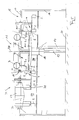
- FIGS. 5 and 6 show, inter alia, a container treatment machine 1b in the form of a filling machine, which in turn is part of a system 31 for filling bottles with a filling material and for subsequently closing these bottles.
- the treatment machine 1 b differs from the processing machine 1 a merely in that the rollers 10 and 11 forming the hanging support of the rotor 16 are not provided on the support plate 17, but freely rotatable on the upper end of the rotor section 16.1, again in the same way in that all the rollers 10 and 11 are located outside the space 19 formed beneath the support plate 17.
- the rotor 24 of the capping machine 23 is rotatably mounted in each case with a ball slewing connection 32. It is understood that instead of this storage can also be provided by the rollers 10 and 11 formed bearing assembly.
Landscapes
- Filling Of Jars Or Cans And Processes For Cleaning And Sealing Jars (AREA)
- Specific Conveyance Elements (AREA)
Description
- Die Erfindung bezieht sich auf eine Behandlungsmaschine für Flaschen oder dergleichen Behälter mit wenigstens einem um eine vertikale Maschinenachse drehbar gelagerten und um diese Maschinenachse umlaufend antreibbaren Rotor und mehreren an dem Rotor gebildeten Behandlungsstationen gemäß Oberbegriff Patentanspruch 1.
- Behandlungsmaschinen dieser Art sind in unterschiedlichen Ausführungen bekannt insbesondere auch als Füllmaschinen, Etikettiermaschinen, Inspektionsmaschinen sowie als Rinser. Zur Lagerung des jeweiligen Rotors werden üblicherweise Kugeldrehverbindungen verwendet, mit denen der Rotor u.a. zur Erzielung der erforderlichen Stabilität auf einem möglichst großen Durchmesser drehbar gelagert ist. Nachteilig hierbei ist insbesondere, dass derartige Kugeldrehverbindungen teuer und auf dem Markt vielfach nur mit erheblichen Lieferfristen erhältlich sind.
- Bekannt sind Behendlungsmaschinen in Form von Behälterfüllmaschinen (
DE 14 32 396 A1 ;US 1 992 329 ), die die Merkmale des Oberbegriffs des Patentanspruches 1 aufweisen und bei denen der jeweilige um eine vertikale Maschinenachse umlaufend antreibbare Rotor sich für eine Axiallagerung mit einer ringförmigen Laufbahn an mehreren an einem Maschinengestell frei drehbar gelagerten Rollen abstutzt. - Bekannt ist weiterhin eine Behandlungsmaschine in Form einer Flaschenfüllmaschine (
DE 10 12 536 B ) mit einem ebenfalls um eine vertikale Maschinenachse umlaufend antreibbaren Rotor, der sich axial über eine Kugeldrehverbindung am Maschinenrahmen abstützt. Zur radialen Abstützung oder Lagerung des Rotors sind am Maschinenrahmen mehrere gegen eine Ringfläche des Rotors anliegende Rollen vorgesehen. - Aufgabe der Erfindung ist es, eine Behälterbehandlungsmaschine aufzuzeigen, die bei ausreichender Stabilität der Lagerung des umlaufenden Rotors mit einem deutlich reduzierten Kostenaufwand realisiert worden kann. Zur Lösung dieser Aufgabe ist eine Behandlungsmaschine entsprechend dem Patentanspruch 1 ausgebildet.
- Durch die erfindungsgemäße Ausbildung können teuere Kugeldrehverbindungen vermieden werden. Dennoch besteht die Möglichkeit, den jeweiligen Rotor auf einem großen Durchmesser bezogen auf den Außendurchmesser des Rotors drehbar zu lagern und damit die erforderliche Stabilität des Rotors und der Lageranordnung für diesen Rotor sicherzustellen sowie auch eine unzulässige Verlagerung der Tangentenpunkte zwischen dem Rotor und mit diesem zusammen wirkender Funktionselemente bei auftretenden Wärmeausdehnungen zu vermeiden.
- Weiterbildungen, Vorteile und Anwendungsmöglichkeiten der Erfindung ergeben sich auch aus der nachfolgenden Beschreibung von Ausführungsbeispielen und aus den Figuren.
- Die Erfindung wird im Folgenden anhand der Figuren an Ausführungsbeispielen näher erläutert. Es zeigen:
- Fig. 1
- in vereinfachter Darstellung und im Schnitt eine Behälterbehandlungsmaschine gemäß der Erfindung in Form einer Füllmaschine;
- Fig. 2
- in vereinfachter Funktionsdarstellung eine Draufsicht auf die Behälterbehandlungsmaschine gemäß der
Fig. 1 ; - Fig. 3
- in einer Darstellung ähnlich
Figur 1 eine Behälterbehandlungsmaschine gemäß der Erfindung in Form einer Füllmaschine, zusammen mit einer Verschließmaschine; - Fig. 4
- in vergrößerter Darstellung eines der Rollenlager der Füllmaschine der
Figur 2 ; - Fig. 5 u. 6
- Darstellungen ähnlich den
Figuren 2 und3 bei einer weiteren Ausführungsform der Erfindung; - Die in der
Figur 1 allgemein mit 1 bezeichnete Behälterbehandlungsmaschine ist als Füllmaschine zum Füllen von Behältern in Form von Flaschen 2 mit einem flüssigen Füllgut oder Produkt ausgebildet. Die Behälterbehandlungsmaschine 1 besteht hierfür aus einem um eine vertikale Maschinenachse MA umlaufend (Pfeil A) antreibbaren Rotor 3, der ringförmig mit einem Rotorabschnitt 3.1 und einem Rotorabschnitt 3.2 ausgeführt ist und an dessen Umfang bzw. Rotorabschnitt 3.1 Füllstationen 4 vorgesehen sind, jeweils bestehend aus einem Füllelement 5 und einem Behälterträger 6, an dem die Flaschen 2 mit ihrer Flaschenachse in vertikaler Richtung orientiert an einem Mündungsflansch hängend gehalten sind. Jedes Füllelement 5 ist über eine Produktleitung 7.1 mit einem Ringkessel 7 am Rotor 3 verbunden. Die zu füllenden Flaschen 2 werden den Füllstationen 4 jeweils über einen von einem umlaufenden Transportstern 8 gebildeten Behältereinlauf zugeführt. Die gefüllten Flaschen 2 werden den Füllstationen 4 an einem den Behälterauslauf bildenden Transportstern 9 entnommen. - Die Besonderheit der Behandlungsmaschine 1 besteht darin, dass die Lagerung des Rotors 3 auf einem relativ großen Durchmesser erfolgt, der bei dieser Ausführungsform etwa 70% des Außendurchmessers entspricht, den der Rotor 3 an seinem die Füllelemente 5 tragende Abschnitt 3.1 aufweist, und zwar mit Hilfe von Rollen 10 und 11 an einer ortsfesten Aufnahme bzw. an einem ortsfesten, d.h. mit dem Rotor 3 nicht umlaufenden Maschinengestell 12 frei drehbar gelagert sind. An dem Maschinengestell 12 sind auch die beiden Lager 8.1 und 9.1 für die Transportsterne 8 und 9 vorgesehen.
- Die Rollen 10 und 11 sind vorzugsweise jeweils in gleichmäßigen Winkelabständen um die Maschinenachse verteilt angeordnet, und zwar bei dieser Ausführungsform die Rollen 10 jeweils frei drehbar um eine Achse radial zur Maschinenachse MA und die Rollen 11 jeweils frei drehbar um Achsen parallel oder in etwa parallel zur Maschinenachse MA.
- Die Rollen 10, die als Gruppe bzw. in ihrer Gesamtheit als axiales Stützlager für den Rotor 3 wirken, liegen jeweils gegen eine an der Unterseite des Rotors bzw. des ringförmigen Rotorabschnittes 3.2 gebildete Lager- oder Lauffläche 10.1 an, die die Maschinenachse MA kreisringförmig umschließt und bei der dargestellten Ausführungsform in einer Ebene senkrecht zur Maschinenachse MA angeordnet ist. Mit der Lauffläche 10.1 stützt sich der Rotor 3 somit auf den Rollen 10 ab.
- An den als Gruppe bzw. in ihrer Gesamtheit ein Radiallager wirkenden und innerhalb der Ringöffnung des Rotors 3 angeordneten Rollen 11 stützt sich der Rotor 3 mit einer Lager- oder Lauffläche 11.1 ab, die die innere, am Rotorabschnitt 3.2 gebildete und die Maschinenachse MA konzentrisch umschließende Ringfläche ist. Bei den Rollen 10 und 11 handelt es sich jeweils um Einzelrollen, d.h. um Rollen, die einzeln bzw. voneinander beabstandet frei drehbar vorgesehen und vorzugsweise einstellbar sind, und zwar sowohl in vertikaler Richtung, als auch radial zur Maschinenachse MA.
- Der Antrieb des Rotors 3 um die Maschinenachse MA erfolgt in dargestellten Ausführungsbeispiel über eine Welle 13, die von einem nicht dargestellten Antrieb der Behälterbehandlungsmaschine 1 umlaufend angetrieben wird. Die Beschickung des Kessels 7 mit dem Produkt bzw. Füllgut erfolgt über eine Leitung 14 und eine Drehdurchführung 15.
- Der besondere Vorteil der Behälterbehandlungsmaschine 1 besteht darin, dass der Rotor 3 unter Vermeidung einer teueren Kugeldrehverbindung auf relativ großem Durchmesser axial sowie radial gelagert ist, und zwar durch eine preiswerte und konstruktiv einfache Lageranordnüng, die von den Rollen 10 und 11 und den zugehörigen Lagerflächen 10.1 und 11.1 gebildet ist. Die Ausbildung der Lagerflächen 10.1 und 11.1 am Rotor 3 hat den Vorteil, dass dieser in der Regel ohnehin als Drehteil gefertigt wird und es daher möglich ist, bei der Herstellung des Rotors 3 zugleich auch die Lagerflächen 10.1 und 11.1 mit der erforderlichen Präzision herzustellen.
- Bei der beschriebenen Lagerung des Rotors 3 mit den Rollen 10 und 11 ist es möglich, auf einen Teilbereich der von den Rollen 10 und 11 gebildeten Lageranordnung die Rollen 11 fest am Maschinengestell 12 und außerhalb dieses Teilbereichs die Rollen 11 oder Lager für diese Rollen beweglich, beispielsweise radial zur Maschinenachse MA beweglich am Maschinengestell 12 vorzusehen, und zwar gegen die Wirkung von die Rollen 11 gegen die Lagerfläche 11.1 andrückenden Zustellkräften. Hierdurch ist dem festen Teilbereich, an dem die Rollen 11 bzw. deren Lager fest am Maschinengestell 12 vorgesehen sind, eine sehr präzise Positionierung des Rotors 3 und der am Rotor vorhandenen Behandlungsstationen bzw. Füllstationen 4 zu angrenzenden Funktionselementen, beispielsweise zu den Transportsternen 8 und 9 gewährleistet. Die genaue räumliche Zuordnung zwischen den Behandlungsstationen am Rotor und äußeren Funktionselementen, beispielsweise den Transportsternen 8 und 9 ist insbesondere auch bei leichtgewichtigen und/oder hängend gehaltenen und transportierten Behältern oder Flaschen 2, wie z.B. PET- oder Kunststoffflaschen von großer Bedeutung, um eine betriebssichere Arbeitsweise einer die Behandlungsmaschine 1 enthaltenden Behandlungs- oder Produktionsstrecke zu gewährleisten.
- Die bewegliche Anordnung der Lager der Rollen 11 außerhalb des festen Teilbereichs ermöglicht einen Ausgleich bei Änderungen des Rotordurchmessers, insbesondere auch bei durch Wärmeausdehnung bedingten Änderungen des Rotordurchmessers, die (Änderungen) z.B. bei einer Heißabfüllung von Produkten sowie auch bei einer Reinigung und/oder Sterilisation der Behandlungsmaschine 1 mit einem heißen Reinigungs- und/oder Sterilisationsmedium auftreten. Dieser Ausgleich von temperaturbedingte Änderungen des Rotordurchmessers erfolgt durch radiale Verlagerung der Maschinenachse MA, wie dies in der
Figur 2 mit der unterbrochenen Linie 3a angedeutet ist. Mit dieser Lösung ist es also möglich, am Übergabebereich zwischen dem jeweiligen Transportstern 8 bzw. 9 und den Behandungs- oder Füllstationen 4 am Rotor 3 eine exakte räumliche Zuordnung einzuhalten, und zwar trotz thermisch bedingter Änderungen des Rotordurchmessers. - Um die, für die fehlerfreie Funktion der Anlagen überaus wichtige, räumliche Zuordnung, der Transportsterne 8 und 9 zum Rotor 3 zu gewährleisten, sind die relativ zum Maschinengestell festen Rollen 11 derart angeordnet, dass sich die Tangentenpunkte zwischen Rotor 3 und den Transportsternen 8.und 9 auch bei auftretenden Wärmeausdehnungen nicht oder aber nur in vertretbarem Maße verlagern. Dazu sind die festen Rollen 11 an den Tangentenpunkten oder aber in deren Nähe angeordnet.
- Es hat sich als besonders vorteilhaft herausgestellt, wenn die sich durch die Wärmeausdehnungen ergebende Verlagerung der Tangentenpunkte kleiner als 1 mm ist.
- Es versteht sich, dass bei dieser Ausführung mit den teilweise festen und teilweise beweglichen Rollen 11 die Lagerfläche 10.1 für die Rollen 10 so ausgebildet ist, dass sich der Rotor 3 in jedem Zustand mit dieser Lagerfläche zuverlässig auf den Rollen 10 abstützt.
- Vorstehend wurde davon ausgegangen, dass die Rollen 10 und 11 am Maschinengestell 12 vorgesehen sind. Grundsätzlich besteht bei entsprechender Ausbildung des Rotors 3 und des Maschinengestells 12 selbstverständlich auch die Möglichkeit, die Rollen 10 bzw. 11 beider Gruppen von Rollen am Rotor 3 zu lagern und die zugehörigen Lager- oder Laufflächen am Maschinengestell 12 auszubilden. Weiterhin besteht auch die Möglichkeit, eine Gruppe von Rollen, beispielsweise die Rollen 10 am Maschinengestell 12 und die andere Gruppe von Rollen, beispielsweise die Rollen 11 am Rotor 3 vorzusehen. Auch bei diesen Varianten können wiederum die Lager für die die radiale Lagerung bewirkenden Rollen 11 teilweise fest und teilweise beweglich vorgesehen sein, und zwar für den vorstehend beschriebenen Ausgleich bei Änderungen des Rotordurchmessers.
- Die
Figur 3 zeigt eine Behandlungsmaschine 1a, die ebenfalls als Füllmaschine ausgebildet ist und am Umfang eines um die vertikale Maschinenachse MA umlaufend antreibbaren Rotors 16 wiederum eine Vielzahl von Behandlungs- bzw. Füllstationen 4 mit jeweils einem Füllelement 5 und einem Behälterträger 6 aufweist. Der Rotor 16 ist an einer oberen Trägerplatte 17 eines Tragrahmens 18 um die vertikale Maschinenachse MA drehbar und hängend gelagert, und zwar wiederum mit den um die Maschinenachse MA verteilt angeordneten Rollen 10 und 11. Diese sind ihrerseits an der Oberseite der Trägerplatte 17 frei drehbar gelagert, und zwar um Achsen radial zur Maschinenachse MA (Rollen 10) bzw. um Achsen parallel zur Maschinenachse MA (Rollen 11). Durch die beschriebene Lagerung des Rotors 16 steht dieser zumindest mit seinem die Füllstationen 4 aufweisenden Teil durch eine Öffnung der Tragplatte 17 über die Unterseite dieser Tragplatte vor. Durch die Ausbildung der Lager- oder Laufflächen 10.1 und 11.1 an dem radial- bzw. flanschartig über den Rotorabschnitt 16.1 wegstehenden Rotorabschnitt 16.3 ist der Rotor 16 mit der von den Rollen 10 und 11 gebildeten Lageranordnung auf einem Durchmesser gelagert, der größer ist als der Außendurchmesser, den der Rotor 16 an dem die Füllstationen 4 aufweisenden Rotorabschnitt 16.1 besitzt. - Der Rotor 16 ist ähnlich dem Rotor 3 mit einem die Maschinenachse MA konzentrisch umschließenden kreisringförmigen Rotorabschnitt 16.1, an dem die Füllelemente 5 vorgesehen sind, sowie mit einem sich radial zur Maschinenachse MA erstreckenden Rotorabschnitt 16.2 ausgebildet. Der Rotorabschnitt 16.1 steht über die Oberseite des Rotorabschnittes 16.2 vor. Am Rotor 16 ist der das Füllgut bzw. Produkt aufnehmende Kessel 7 angeordnet, der über Produktleitungen 7.1 mit den Füllelementen 5 in Verbindung steht.
- Der Trägerrahmen 18 weist weiterhin Wandabschnitte oder ein tragendes Gestell 19 auf, mit dem die mit ihren Oberflächenseiten in horizontalen Ebenen angeordnete Trägerplatte 17 von einem Untergrund 20 beabstandet ist.
- Die mit den Rollen 10 und 11 zusammenwirkenden Lauf- und Lagerflächen 10.1 bzw. 11.1 sind bei der Behandlungsmaschine 1a an einem oberen flanschartig radial nach außen wegstehenden Rotorabschnitt 16.3 gebildet, in den der Rotorabschnitt 16.1 an der Oberseite des Rotors 16 übergeht. Wie insbesondere auch die
Figur 4 zeigt, bildet die Unterseite des Rotorabschnittes 16.3 die Lagerfläche 10.1 und die äußere kreiszylinderförmige, die Maschinenachse MA konzentrisch umschließende Ringfläche des Rotorabschnittes 16.3 die Lagerfläche 11.1. - Die zu füllenden Flaschen 2 werden den Füllstationen 4 über einen den Behältereinlauf bildenden Transportstern 21 zugeführt. Die gefüllten Flaschen 2 werden den Füllstationen 4 an einem den Behälterauslauf der Behandlungsmaschine 1a bildenden Transportstern 22 entnommen und an eine Verschließmaschine 23 bzw. jeweils an eine der Verschließstationen 25 übergeben, die an einem umlaufenden Rotor 24 der Verschließmaschine 23 vorgesehen sind.
- Die Füllstationen 4, die Transportsterne 21 und 22 sowie die Verschließstationen 25 und auch weitere, nicht dargestellte Transportelemente für die Flaschen 2 sind jeweils für eine hängende Halterung oder einen hängenden Transport der Flaschen 2 ausgebildet. Weiterhin sind die Transportsterne 21 und 22 sowie die Rotoren 16 und 24 hängend an der Tragplatte 17 derart gehalten, dass sich die Transportsterne 21 und 22 insbesondere auch mit ihrem mit den Flaschen 2 zusammenwirkenden Abschnitt sowie die Füll- und Verschließstationen 4 bzw. 25 unterhalb der Tragplatte 17 befinden, während sämtliche Lager- und Antriebselemente, auch die Rollen 10 und 11 oberhalb der Tragplatte 17 vorgesehen sind.
- Durch eine Dichtung 26 ist der Übergang zwischen der Tragplatte 17 und dem Rotor 16 dicht verschlossen. Entsprechende Dichtungen 27 und 28 sind auch an den Wellen 21.1 und 22.1 der Transportsterne 21 und 22 sowie am Übergang zwischen dem Rotor 24 und der Tragplatte 27 vorgesehen.
- Der Raum unterhalb der Rotoren 16 und 24 sowie der Transportstern 21 und 22, in dem (Raum) sich die Flaschen 2 befinden, ist bei der dargestellten Ausführungsform nach außen hin verschlossen, und zwar einerseits durch die Trägerplatte 17 und die die Öffnungen in dieser Trägerplatte ausfüllenden Rotoren 16 und 24 sowie auch durch das Traggestell 19 bildende Wände und einen Zwischenboden 30, der parallel zur Tragplatte 17 und parallel zu dieser Tragplatte unterhalb der Bewegungsbahn der Flaschen 2 vorgesehen ist. Die dargestellte, u.a. die Behälterbehandlungsmaschine 1a, die Verschließmaschine 23 sowie die Transportsterne 21 und 22 aufweisende Anlage 31 kann somit zum sterilen oder aseptischen Abfüllen eines Produktes in die Flasche 2 verwendet werden, die dieser Anlage 31 bzw. dem sterilen Raum 29 über eine Einlassschleuse zugeführt und nach dem Füllen und Verschließen aus dem Raum 29 über eine Auslassschleuse abgeführt werden.
- Die
Figuren 5 und6 zeigen u.a. eine Behälterbehandlungsmaschine 1b in Form einer Füllmaschine, die wiederum Bestandteil einer Anlage 31 zum Füllen von Flaschen mit einem Füllgut und zum anschließenden Verschließen dieser Flaschen ist. Die Behandlungsmaschine 1 b unterscheidet sich von der Behandlungsmaschine 1 a lediglich dadurch, dass die die hängende Lagerung des Rotors 16 bildenden Rollen 10 und 11 nicht an der Tragplatte 17 vorgesehen sind, sondern frei drehbar an dem oberen Ende des Rotorabschnittes 16.1, und zwar wiederum so, dass sich sämtliche Rollen 10 und 11 außerhalb des unterhalb der Tragplatte 17 gebildeten Raumes 19 befinden. - Bei den in den
Figuren 3 - 6 dargestellten Anlagen 31 ist der Rotor 24 der Verschließmaschine 23 jeweils mit einer Kugeldrehverbindung 32 drehbar gelagert. Es versteht sich, dass anstelle dieser Lagerung ebenfalls eine von den Rollen 10 und 11 gebildete Lageranordnung vorgesehen sein kann. - Die Erfindung wurde voranstehend an Ausführungsbeispielen beschrieben.
-
- 1, 1a, 1b
- Behandlungsmaschine
- 2
- Flasche
- 3
- Rotor
- 3a
- thermische Verformung des Rotors
- 3.1,3.2
- Rotorabschnitt
- 4
- Füllstation
- 5
- Füllelement
- 6
- Behälterträger
- 7
- Kessel
- 7.1
- Produktleitung
- 8, 9
- Transportstern
- 8.1,9.1
- Lager
- 10, 11
- Einzelrolle
- 10.1, 11.1
- Lager- oder Lauffläche
- 12
- Maschinengestell
- 13
- Welle
- 14
- Leitung
- 15
- Drehdurchführung
- 16
- Rotor
- 16.1, 16.2, 16.3
- Rotorabschnitt
- 17
- Tragplatte
- 18
- Tragrahmen
- 19
- Traggestell
- 20
- Untergrund
- 21,22
- Transportstern
- 21.1.,22.1
- Welle
- 23
- Verschließmaschine
- 24
- Rotor
- 25
- Verschließstation
- 26, 27, 28
- Dichtung
- 29
- Raum
- 30
- Zwischenboden
- 31
- Anlage
- 32
- Kugeldrehverbindung
- A
- Drehrichtung des Rotors 3 bzw. 16
- MA
- Maschinenachse
Claims (10)
- Behandlungsmaschine zum Behandeln von Flaschen oder dergleichen Behältern (2), mit wenigstens einem Rotor (3, 16), der mit wenigstens einer Lageranordnung (10, 11) um eine Maschinenachse (MA) drehbar gelagert ist, sowie mit mehreren am Rotor (3, 16) vorgesehenen Behandlungsstationen (4), wobei die Lagerung des Rotors (3, 16) über mehrere um die Maschinenachse (MA) verteilt angeordnete und die Lageranordnung bildende Rollen (10, 11) erfolgt, wobei wenigstens ein mit dem Rotor (3, 16) oder mit den Behandlungsstationen (4) zusammenwirkendes Funktionselement (8, 9; 21, 22) vorgesehen ist, dadurch gekennzeichnet, dass zumindest ein Teil der Rollen (10, 11) zumindest in einer Raumachse und/oder Raumebene einstellbar und/oder beweglich angeordnet ist, dass zumindest die Rollen (10, 11) an einem dem Funktionselement gegenüberliegenden Bereich der Lageranordnung beweglich, vorzugsweise in einer Achsrichtung radial zur Maschinenachse (MA) beweglich vorgesehen sind und dass zumindest ein Teil der Rollen (10, 11) relativ fest an Tangentenpunkten zwischen dem Rotor (3) und den Funktionselementen (8, 9) oder aber in deren Nähe angeordnet ist, sodass sich die Tangentenpunkte zwischen dem Rotor (3) und den Funktionselementen (8, 9) bei auftretenden Wärmeausdehnungen nicht in unzulässiger Weise verlagern.
- Behandlungsmaschine nach Anspruch 1, dadurch gekennzeichnet, dass die Rollen (10, 11) frei drehbar gelagert sind.
- Behandlungsmaschine nach einem der vorhergehenden Ansprüche, dadurch gekennzeichnet dass die Rollen (10, 11) zumindest teilweise an einem mit dem Rotor (3, 16) nicht umlaufenden Maschinen- oder Anlagenelement (12, 17) vorgesehen sind und mit wenigstens einer die Maschinenachse (MA) umschließenden Lager- oder Lauffläche (10.1, 11.1) am Rotor (3, 16) zusammenwirken, und/oder dass die Rollen (10, 11) zumindest teilweise am Rotor (3, 16) vorgesehen sind und mit wenigstens einer die Maschinenachse (MA) umschließenden Lager- oder Lauffläche (10.1, 11.1) an einem mit dem Rotor (3, 16) nicht umlaufenden Maschinen- oder Anlagenelement (12, 17) zusammenwirken.
- Behandlungsmaschine nach einem der vorhergehenden Ansprüche, dadurch gekennzeichnet, dass die Verlagerung der Tangentenpunkte zwischen dem Rotor (3) und den Funktionselementen (8, 9) bei auftretenden Wärmeausdehnungen kleiner als 1 mm ist.
- Behandlungsmaschine nach einem der vorhergehenden Ansprüche, dadurch gekennzeichnet, dass zumindest ein Teil der fest mit dem Maschinengestell verbundenen Rollen (10, 11) in den Tangentenpunkten zwischen Rotor (3) und den Funktionselementen (8, 9) oder in deren Nähe angeordnet ist.
- Behandlungsmaschine nach einem der vorhergehenden Ansprüche, dadurch gekennzeichnet, dass der Rotor (3) sich über die von den Rollen (10, 11) gebildete Lageranordnung auf einem Maschinengestell (12) abstützt und/oder an dem Maschinen- oder Anlagenelement (17) hängend gehalten ist.
- Behandlungsmaschine nach einem der vorhergehenden Ansprüche, dadurch gekennzeichnet, dass die Rollen (10, 11) wenigstens zwei Gruppen von Rollen bilden, von denen die Rollen (10) einer Gruppe einer axialen oder im Wesentlichen axialen Lagerung des Rotors (3, 16) und die Rollen (16) einer weiteren Gruppe einer radialen oder im Wesentlichen radialen Lagerung des Rotors (3, 16) dienen.
- Behandlungsmaschine nach einem der vorhergehenden Ansprüche, dadurch gekennzeichnet, dass der Rotor (3, 16) durch die von den Rollen (10, 11) gebildete Lageranordnung auf einem Durchmesser gelagert ist, der wenigstens 50%, vorzugsweise wenigstens 65 % des Außendurchmessers des Rotors (3, 16) entspricht.
- Behandlungsmaschine nach Anspruch 8, dadurch gekennzeichnet, dass der Rotor (16) durch die von den Rollen (10, 11) gebildete Lageranordnung an einem Durchmesser gelagert, der größer ist als der Durchmesser des Rotors (16) im Bereich der Behandlungsstationen (4).
- Behandlungsmaschine nach einem der vorhergehenden Ansprüche, gekennzeichnet durch ihre Ausbildung als Füllmaschine, Rinser. Etikettiermaschine oder Inspektionsmaschine.
Priority Applications (1)
| Application Number | Priority Date | Filing Date | Title |
|---|---|---|---|
| SI200931339T SI2288571T1 (sl) | 2008-05-15 | 2009-04-29 | Obdelovalni stroj za steklenice ali podobne vsebnike |
Applications Claiming Priority (2)
| Application Number | Priority Date | Filing Date | Title |
|---|---|---|---|
| DE102008023776A DE102008023776A1 (de) | 2008-05-15 | 2008-05-15 | Behandlungsmaschine für Flaschen oder dergleichen Behälter |
| PCT/EP2009/003093 WO2009138167A1 (de) | 2008-05-15 | 2009-04-29 | Behandlungsmaschine für flaschen oder dergleichen behälter |
Publications (2)
| Publication Number | Publication Date |
|---|---|
| EP2288571A1 EP2288571A1 (de) | 2011-03-02 |
| EP2288571B1 true EP2288571B1 (de) | 2015-11-25 |
Family
ID=40934040
Family Applications (1)
| Application Number | Title | Priority Date | Filing Date |
|---|---|---|---|
| EP09745501.8A Not-in-force EP2288571B1 (de) | 2008-05-15 | 2009-04-29 | Behandlungsmaschine für flaschen oder dergleichen behälter |
Country Status (7)
| Country | Link |
|---|---|
| US (1) | US9139410B2 (de) |
| EP (1) | EP2288571B1 (de) |
| JP (1) | JP5639044B2 (de) |
| BR (1) | BRPI0905914A2 (de) |
| DE (1) | DE102008023776A1 (de) |
| SI (1) | SI2288571T1 (de) |
| WO (1) | WO2009138167A1 (de) |
Families Citing this family (5)
| Publication number | Priority date | Publication date | Assignee | Title |
|---|---|---|---|---|
| DE102010047838A1 (de) * | 2010-09-28 | 2011-12-01 | Carl Zeiss Smt Gmbh | Aktiv kühlbares optisches Element sowie optisches System mit einem solchen optischen Element |
| US9061874B2 (en) | 2011-02-10 | 2015-06-23 | Khs Gmbh | Container transport device having pliable bottle supports |
| DE102011010955B4 (de) | 2011-02-10 | 2013-01-31 | Khs Gmbh | Verschiebbare Transportsterne |
| DE102011010954A1 (de) | 2011-02-10 | 2012-08-16 | Khs Gmbh | Nachgiebige Flaschenauflage |
| DE102011015670A1 (de) * | 2011-03-31 | 2012-10-04 | Khs Gmbh | Speichervorrichtung |
Family Cites Families (11)
| Publication number | Priority date | Publication date | Assignee | Title |
|---|---|---|---|---|
| US1992329A (en) | 1931-09-22 | 1935-02-26 | Fmc Corp | Filling machine |
| US2591739A (en) * | 1948-05-26 | 1952-04-08 | Crown Cork & Seal Co | Filling machine |
| DE1012536B (de) | 1953-10-19 | 1957-07-18 | Hugo Mosblech Kom Ges | Flaschenfuellmaschine |
| US3182691A (en) * | 1961-10-12 | 1965-05-11 | Pneumatic Scale Corp | Container filling method and machine |
| DE1432396A1 (de) | 1962-03-16 | 1968-11-28 | Pneumatic Scale Corp | Behaelter-Fuellmaschine |
| DE3208234C2 (de) * | 1982-03-06 | 1984-02-16 | Krones Ag Hermann Kronseder Maschinenfabrik, 8402 Neutraubling | Vorrichtung zum Aufsetzen von Schlauchabschnitten aus Kunststoffolie o.dgl. auf Gefäße |
| US4514966A (en) * | 1982-12-02 | 1985-05-07 | Konstantin Anatole E | Shrink banding machine for use with thin film |
| JPS6067315A (ja) * | 1983-09-21 | 1985-04-17 | Mitsubishi Heavy Ind Ltd | 自動求芯制御機能を有する芯なし環状回転体 |
| DE4104313A1 (de) * | 1991-02-13 | 1992-08-20 | Mette Manfred | Portioniervorrichtung fuer fliessfaehige massen |
| US6701697B2 (en) * | 2001-12-04 | 2004-03-09 | Ag-Pak, Inc. | Carousel bagger |
| DE10346044B4 (de) * | 2003-10-02 | 2016-04-28 | Khs Gmbh | Behandlungsmaschine für Behälter wie Flaschen, Dosen und dgl. |
-
2008
- 2008-05-15 DE DE102008023776A patent/DE102008023776A1/de not_active Withdrawn
-
2009
- 2009-04-29 WO PCT/EP2009/003093 patent/WO2009138167A1/de active Application Filing
- 2009-04-29 BR BRPI0905914-8A patent/BRPI0905914A2/pt not_active Application Discontinuation
- 2009-04-29 SI SI200931339T patent/SI2288571T1/sl unknown
- 2009-04-29 US US12/992,013 patent/US9139410B2/en not_active Expired - Fee Related
- 2009-04-29 JP JP2011508811A patent/JP5639044B2/ja not_active Expired - Fee Related
- 2009-04-29 EP EP09745501.8A patent/EP2288571B1/de not_active Not-in-force
Also Published As
| Publication number | Publication date |
|---|---|
| SI2288571T1 (sl) | 2016-01-29 |
| BRPI0905914A2 (pt) | 2015-06-30 |
| JP5639044B2 (ja) | 2014-12-10 |
| WO2009138167A1 (de) | 2009-11-19 |
| EP2288571A1 (de) | 2011-03-02 |
| JP2011522757A (ja) | 2011-08-04 |
| DE102008023776A1 (de) | 2009-11-26 |
| US9139410B2 (en) | 2015-09-22 |
| US20110072761A1 (en) | 2011-03-31 |
Similar Documents
| Publication | Publication Date | Title |
|---|---|---|
| EP1486454B1 (de) | Behälterbehandlungsmaschine mit abgeschlossenem raum | |
| EP2387534B1 (de) | Behälterbehandlungsmaschine | |
| EP2288571B1 (de) | Behandlungsmaschine für flaschen oder dergleichen behälter | |
| EP2504244B1 (de) | Vorrichtung zum aseptischen oder sterilen behandeln von packmitteln | |
| EP2665676B1 (de) | Füllelement mit einer spritzdüse oder spritzdüsenanordnung, sowie verfahren zum reinigen von maschinenelementen | |
| WO2008009400A1 (de) | Behandlungsmaschine | |
| EP3003879B1 (de) | Verfahren zur behandlung von behältern sowie behälterbehandlungsmaschine | |
| DE102011111483A1 (de) | Behälterbehandlungsmaschine | |
| EP2999635A1 (de) | Behälterbehandlungsmaschine sowie verfahren zum betrieb einer behälterbehandlungsmaschine | |
| EP2328829B1 (de) | Behälterbehandlungsmachine, insbesondere verschliessmaschine | |
| WO2017072353A2 (de) | Vorrichtung zum befüllen von behältern mit einem füllprodukt | |
| EP2976290A1 (de) | Füllmaschine | |
| EP2847123B1 (de) | Füllmaschine | |
| DE102017105509A1 (de) | Verschließmaschine | |
| DE102012019161A1 (de) | Füllmaschine | |
| DE102015115729B4 (de) | Behältertransporteur | |
| DE202011107657U1 (de) | Maschine zum Aufbringen von abnehmbaren Verschlussvorrichtungen auf entsprechenden Behältern | |
| EP2964562B1 (de) | Maschine und verfahren zum füllen von behältern sowie reinigungsverfahren | |
| EP3530598B1 (de) | Antriebssystem für eine behältertransportstrecke sowie behältertransportstrecke mit einem solchen antriebssystem | |
| DE19644399C1 (de) | Füllerreinigung mit in Sektoren teilbarer, ringförmiger Drehdurchführung | |
| EP2387543A2 (de) | Behälterbehandlungsmaschine | |
| EP2928808A1 (de) | Füllmaschine | |
| DE29502209U1 (de) | Vorrichtung zur Teigbearbeitung mit Drehkörpern | |
| DE102007058046A1 (de) | Vorrichtung zum Behandeln von Flaschen oder dergleichen Behälter, insbesondere Füllmaschine | |
| DE102021132441A1 (de) | Verschließvorrichtung für Behälterbehandlungsanlage |
Legal Events
| Date | Code | Title | Description |
|---|---|---|---|
| PUAI | Public reference made under article 153(3) epc to a published international application that has entered the european phase |
Free format text: ORIGINAL CODE: 0009012 |
|
| 17P | Request for examination filed |
Effective date: 20101215 |
|
| AK | Designated contracting states |
Kind code of ref document: A1 Designated state(s): AT BE BG CH CY CZ DE DK EE ES FI FR GB GR HR HU IE IS IT LI LT LU LV MC MK MT NL NO PL PT RO SE SI SK TR |
|
| AX | Request for extension of the european patent |
Extension state: AL BA RS |
|
| DAX | Request for extension of the european patent (deleted) | ||
| 17Q | First examination report despatched |
Effective date: 20130909 |
|
| GRAP | Despatch of communication of intention to grant a patent |
Free format text: ORIGINAL CODE: EPIDOSNIGR1 |
|
| INTG | Intention to grant announced |
Effective date: 20150723 |
|
| GRAS | Grant fee paid |
Free format text: ORIGINAL CODE: EPIDOSNIGR3 |
|
| GRAA | (expected) grant |
Free format text: ORIGINAL CODE: 0009210 |
|
| AK | Designated contracting states |
Kind code of ref document: B1 Designated state(s): AT BE BG CH CY CZ DE DK EE ES FI FR GB GR HR HU IE IS IT LI LT LU LV MC MK MT NL NO PL PT RO SE SI SK TR |
|
| REG | Reference to a national code |
Ref country code: GB Ref legal event code: FG4D Free format text: NOT ENGLISH |
|
| REG | Reference to a national code |
Ref country code: CH Ref legal event code: EP |
|
| REG | Reference to a national code |
Ref country code: AT Ref legal event code: REF Ref document number: 762484 Country of ref document: AT Kind code of ref document: T Effective date: 20151215 |
|
| REG | Reference to a national code |
Ref country code: IE Ref legal event code: FG4D Free format text: LANGUAGE OF EP DOCUMENT: GERMAN |
|
| REG | Reference to a national code |
Ref country code: DE Ref legal event code: R096 Ref document number: 502009011865 Country of ref document: DE |
|
| REG | Reference to a national code |
Ref country code: LT Ref legal event code: MG4D |
|
| REG | Reference to a national code |
Ref country code: NL Ref legal event code: MP Effective date: 20160225 |
|
| REG | Reference to a national code |
Ref country code: FR Ref legal event code: PLFP Year of fee payment: 8 |
|
| PG25 | Lapsed in a contracting state [announced via postgrant information from national office to epo] |
Ref country code: NL Free format text: LAPSE BECAUSE OF FAILURE TO SUBMIT A TRANSLATION OF THE DESCRIPTION OR TO PAY THE FEE WITHIN THE PRESCRIBED TIME-LIMIT Effective date: 20151125 Ref country code: ES Free format text: LAPSE BECAUSE OF FAILURE TO SUBMIT A TRANSLATION OF THE DESCRIPTION OR TO PAY THE FEE WITHIN THE PRESCRIBED TIME-LIMIT Effective date: 20151125 Ref country code: NO Free format text: LAPSE BECAUSE OF FAILURE TO SUBMIT A TRANSLATION OF THE DESCRIPTION OR TO PAY THE FEE WITHIN THE PRESCRIBED TIME-LIMIT Effective date: 20160225 Ref country code: IS Free format text: LAPSE BECAUSE OF FAILURE TO SUBMIT A TRANSLATION OF THE DESCRIPTION OR TO PAY THE FEE WITHIN THE PRESCRIBED TIME-LIMIT Effective date: 20160325 Ref country code: HR Free format text: LAPSE BECAUSE OF FAILURE TO SUBMIT A TRANSLATION OF THE DESCRIPTION OR TO PAY THE FEE WITHIN THE PRESCRIBED TIME-LIMIT Effective date: 20151125 Ref country code: LT Free format text: LAPSE BECAUSE OF FAILURE TO SUBMIT A TRANSLATION OF THE DESCRIPTION OR TO PAY THE FEE WITHIN THE PRESCRIBED TIME-LIMIT Effective date: 20151125 |
|
| PG25 | Lapsed in a contracting state [announced via postgrant information from national office to epo] |
Ref country code: LV Free format text: LAPSE BECAUSE OF FAILURE TO SUBMIT A TRANSLATION OF THE DESCRIPTION OR TO PAY THE FEE WITHIN THE PRESCRIBED TIME-LIMIT Effective date: 20151125 Ref country code: FI Free format text: LAPSE BECAUSE OF FAILURE TO SUBMIT A TRANSLATION OF THE DESCRIPTION OR TO PAY THE FEE WITHIN THE PRESCRIBED TIME-LIMIT Effective date: 20151125 Ref country code: PT Free format text: LAPSE BECAUSE OF FAILURE TO SUBMIT A TRANSLATION OF THE DESCRIPTION OR TO PAY THE FEE WITHIN THE PRESCRIBED TIME-LIMIT Effective date: 20160325 Ref country code: PL Free format text: LAPSE BECAUSE OF FAILURE TO SUBMIT A TRANSLATION OF THE DESCRIPTION OR TO PAY THE FEE WITHIN THE PRESCRIBED TIME-LIMIT Effective date: 20151125 Ref country code: GR Free format text: LAPSE BECAUSE OF FAILURE TO SUBMIT A TRANSLATION OF THE DESCRIPTION OR TO PAY THE FEE WITHIN THE PRESCRIBED TIME-LIMIT Effective date: 20160226 Ref country code: SE Free format text: LAPSE BECAUSE OF FAILURE TO SUBMIT A TRANSLATION OF THE DESCRIPTION OR TO PAY THE FEE WITHIN THE PRESCRIBED TIME-LIMIT Effective date: 20151125 |
|
| PG25 | Lapsed in a contracting state [announced via postgrant information from national office to epo] |
Ref country code: CZ Free format text: LAPSE BECAUSE OF FAILURE TO SUBMIT A TRANSLATION OF THE DESCRIPTION OR TO PAY THE FEE WITHIN THE PRESCRIBED TIME-LIMIT Effective date: 20151125 |
|
| REG | Reference to a national code |
Ref country code: DE Ref legal event code: R097 Ref document number: 502009011865 Country of ref document: DE |
|
| PG25 | Lapsed in a contracting state [announced via postgrant information from national office to epo] |
Ref country code: BE Free format text: LAPSE BECAUSE OF NON-PAYMENT OF DUE FEES Effective date: 20160430 Ref country code: EE Free format text: LAPSE BECAUSE OF FAILURE TO SUBMIT A TRANSLATION OF THE DESCRIPTION OR TO PAY THE FEE WITHIN THE PRESCRIBED TIME-LIMIT Effective date: 20151125 Ref country code: SK Free format text: LAPSE BECAUSE OF FAILURE TO SUBMIT A TRANSLATION OF THE DESCRIPTION OR TO PAY THE FEE WITHIN THE PRESCRIBED TIME-LIMIT Effective date: 20151125 Ref country code: DK Free format text: LAPSE BECAUSE OF FAILURE TO SUBMIT A TRANSLATION OF THE DESCRIPTION OR TO PAY THE FEE WITHIN THE PRESCRIBED TIME-LIMIT Effective date: 20151125 Ref country code: RO Free format text: LAPSE BECAUSE OF FAILURE TO SUBMIT A TRANSLATION OF THE DESCRIPTION OR TO PAY THE FEE WITHIN THE PRESCRIBED TIME-LIMIT Effective date: 20151125 |
|
| PLBE | No opposition filed within time limit |
Free format text: ORIGINAL CODE: 0009261 |
|
| STAA | Information on the status of an ep patent application or granted ep patent |
Free format text: STATUS: NO OPPOSITION FILED WITHIN TIME LIMIT |
|
| 26N | No opposition filed |
Effective date: 20160826 |
|
| REG | Reference to a national code |
Ref country code: CH Ref legal event code: PL |
|
| GBPC | Gb: european patent ceased through non-payment of renewal fee |
Effective date: 20160429 |
|
| PG25 | Lapsed in a contracting state [announced via postgrant information from national office to epo] |
Ref country code: LU Free format text: LAPSE BECAUSE OF FAILURE TO SUBMIT A TRANSLATION OF THE DESCRIPTION OR TO PAY THE FEE WITHIN THE PRESCRIBED TIME-LIMIT Effective date: 20160429 |
|
| REG | Reference to a national code |
Ref country code: IE Ref legal event code: MM4A |
|
| PG25 | Lapsed in a contracting state [announced via postgrant information from national office to epo] |
Ref country code: GB Free format text: LAPSE BECAUSE OF NON-PAYMENT OF DUE FEES Effective date: 20160429 Ref country code: CH Free format text: LAPSE BECAUSE OF NON-PAYMENT OF DUE FEES Effective date: 20160430 Ref country code: LI Free format text: LAPSE BECAUSE OF NON-PAYMENT OF DUE FEES Effective date: 20160430 |
|
| REG | Reference to a national code |
Ref country code: FR Ref legal event code: PLFP Year of fee payment: 9 |
|
| PG25 | Lapsed in a contracting state [announced via postgrant information from national office to epo] |
Ref country code: IE Free format text: LAPSE BECAUSE OF NON-PAYMENT OF DUE FEES Effective date: 20160429 |
|
| REG | Reference to a national code |
Ref country code: AT Ref legal event code: MM01 Ref document number: 762484 Country of ref document: AT Kind code of ref document: T Effective date: 20160429 |
|
| PG25 | Lapsed in a contracting state [announced via postgrant information from national office to epo] |
Ref country code: AT Free format text: LAPSE BECAUSE OF NON-PAYMENT OF DUE FEES Effective date: 20160429 |
|
| REG | Reference to a national code |
Ref country code: FR Ref legal event code: PLFP Year of fee payment: 10 |
|
| PG25 | Lapsed in a contracting state [announced via postgrant information from national office to epo] |
Ref country code: HU Free format text: LAPSE BECAUSE OF FAILURE TO SUBMIT A TRANSLATION OF THE DESCRIPTION OR TO PAY THE FEE WITHIN THE PRESCRIBED TIME-LIMIT; INVALID AB INITIO Effective date: 20090429 Ref country code: CY Free format text: LAPSE BECAUSE OF FAILURE TO SUBMIT A TRANSLATION OF THE DESCRIPTION OR TO PAY THE FEE WITHIN THE PRESCRIBED TIME-LIMIT Effective date: 20151125 |
|
| PG25 | Lapsed in a contracting state [announced via postgrant information from national office to epo] |
Ref country code: TR Free format text: LAPSE BECAUSE OF FAILURE TO SUBMIT A TRANSLATION OF THE DESCRIPTION OR TO PAY THE FEE WITHIN THE PRESCRIBED TIME-LIMIT Effective date: 20151125 Ref country code: MC Free format text: LAPSE BECAUSE OF FAILURE TO SUBMIT A TRANSLATION OF THE DESCRIPTION OR TO PAY THE FEE WITHIN THE PRESCRIBED TIME-LIMIT Effective date: 20151125 Ref country code: MT Free format text: LAPSE BECAUSE OF FAILURE TO SUBMIT A TRANSLATION OF THE DESCRIPTION OR TO PAY THE FEE WITHIN THE PRESCRIBED TIME-LIMIT Effective date: 20151125 Ref country code: MK Free format text: LAPSE BECAUSE OF FAILURE TO SUBMIT A TRANSLATION OF THE DESCRIPTION OR TO PAY THE FEE WITHIN THE PRESCRIBED TIME-LIMIT Effective date: 20151125 |
|
| PG25 | Lapsed in a contracting state [announced via postgrant information from national office to epo] |
Ref country code: BG Free format text: LAPSE BECAUSE OF FAILURE TO SUBMIT A TRANSLATION OF THE DESCRIPTION OR TO PAY THE FEE WITHIN THE PRESCRIBED TIME-LIMIT Effective date: 20151125 |
|
| PGFP | Annual fee paid to national office [announced via postgrant information from national office to epo] |
Ref country code: DE Payment date: 20180420 Year of fee payment: 10 |
|
| PGFP | Annual fee paid to national office [announced via postgrant information from national office to epo] |
Ref country code: FR Payment date: 20180420 Year of fee payment: 10 Ref country code: SI Payment date: 20180403 Year of fee payment: 10 Ref country code: IT Payment date: 20180423 Year of fee payment: 10 |
|
| REG | Reference to a national code |
Ref country code: DE Ref legal event code: R119 Ref document number: 502009011865 Country of ref document: DE |
|
| PG25 | Lapsed in a contracting state [announced via postgrant information from national office to epo] |
Ref country code: DE Free format text: LAPSE BECAUSE OF NON-PAYMENT OF DUE FEES Effective date: 20191101 |
|
| PG25 | Lapsed in a contracting state [announced via postgrant information from national office to epo] |
Ref country code: SI Free format text: LAPSE BECAUSE OF NON-PAYMENT OF DUE FEES Effective date: 20190430 Ref country code: FR Free format text: LAPSE BECAUSE OF NON-PAYMENT OF DUE FEES Effective date: 20190430 |
|
| PG25 | Lapsed in a contracting state [announced via postgrant information from national office to epo] |
Ref country code: IT Free format text: LAPSE BECAUSE OF NON-PAYMENT OF DUE FEES Effective date: 20190429 |