EP2288570B1 - Dispositif d'arrêt - Google Patents
Dispositif d'arrêt Download PDFInfo
- Publication number
- EP2288570B1 EP2288570B1 EP09745462A EP09745462A EP2288570B1 EP 2288570 B1 EP2288570 B1 EP 2288570B1 EP 09745462 A EP09745462 A EP 09745462A EP 09745462 A EP09745462 A EP 09745462A EP 2288570 B1 EP2288570 B1 EP 2288570B1
- Authority
- EP
- European Patent Office
- Prior art keywords
- locking
- catch
- component
- fixing device
- catching
- Prior art date
- Legal status (The legal status is an assumption and is not a legal conclusion. Google has not performed a legal analysis and makes no representation as to the accuracy of the status listed.)
- Not-in-force
Links
Images


Classifications
-
- B—PERFORMING OPERATIONS; TRANSPORTING
- B66—HOISTING; LIFTING; HAULING
- B66F—HOISTING, LIFTING, HAULING OR PUSHING, NOT OTHERWISE PROVIDED FOR, e.g. DEVICES WHICH APPLY A LIFTING OR PUSHING FORCE DIRECTLY TO THE SURFACE OF A LOAD
- B66F7/00—Lifting frames, e.g. for lifting vehicles; Platform lifts
- B66F7/06—Lifting frames, e.g. for lifting vehicles; Platform lifts with platforms supported by levers for vertical movement
- B66F7/08—Lifting frames, e.g. for lifting vehicles; Platform lifts with platforms supported by levers for vertical movement hydraulically or pneumatically operated
-
- B—PERFORMING OPERATIONS; TRANSPORTING
- B66—HOISTING; LIFTING; HAULING
- B66F—HOISTING, LIFTING, HAULING OR PUSHING, NOT OTHERWISE PROVIDED FOR, e.g. DEVICES WHICH APPLY A LIFTING OR PUSHING FORCE DIRECTLY TO THE SURFACE OF A LOAD
- B66F7/00—Lifting frames, e.g. for lifting vehicles; Platform lifts
- B66F7/06—Lifting frames, e.g. for lifting vehicles; Platform lifts with platforms supported by levers for vertical movement
- B66F7/065—Scissor linkages, i.e. X-configuration
-
- B—PERFORMING OPERATIONS; TRANSPORTING
- B66—HOISTING; LIFTING; HAULING
- B66F—HOISTING, LIFTING, HAULING OR PUSHING, NOT OTHERWISE PROVIDED FOR, e.g. DEVICES WHICH APPLY A LIFTING OR PUSHING FORCE DIRECTLY TO THE SURFACE OF A LOAD
- B66F7/00—Lifting frames, e.g. for lifting vehicles; Platform lifts
- B66F7/28—Constructional details, e.g. end stops, pivoting supporting members, sliding runners adjustable to load dimensions
-
- Y—GENERAL TAGGING OF NEW TECHNOLOGICAL DEVELOPMENTS; GENERAL TAGGING OF CROSS-SECTIONAL TECHNOLOGIES SPANNING OVER SEVERAL SECTIONS OF THE IPC; TECHNICAL SUBJECTS COVERED BY FORMER USPC CROSS-REFERENCE ART COLLECTIONS [XRACs] AND DIGESTS
- Y10—TECHNICAL SUBJECTS COVERED BY FORMER USPC
- Y10T—TECHNICAL SUBJECTS COVERED BY FORMER US CLASSIFICATION
- Y10T29/00—Metal working
- Y10T29/49—Method of mechanical manufacture
- Y10T29/49826—Assembling or joining
- Y10T29/49947—Assembling or joining by applying separate fastener
-
- Y—GENERAL TAGGING OF NEW TECHNOLOGICAL DEVELOPMENTS; GENERAL TAGGING OF CROSS-SECTIONAL TECHNOLOGIES SPANNING OVER SEVERAL SECTIONS OF THE IPC; TECHNICAL SUBJECTS COVERED BY FORMER USPC CROSS-REFERENCE ART COLLECTIONS [XRACs] AND DIGESTS
- Y10—TECHNICAL SUBJECTS COVERED BY FORMER USPC
- Y10T—TECHNICAL SUBJECTS COVERED BY FORMER US CLASSIFICATION
- Y10T403/00—Joints and connections
- Y10T403/32—Articulated members
- Y10T403/32254—Lockable at fixed position
Definitions
- the invention relates to a locking device for releasably locking relatively movable components, in particular for use on lifting devices, with the two mutually linearly movable parts can be releasably locked, which also ensures that an unwanted entanglement of the locking device is excluded and thus blocking or Failure of the apparatus, on which the locking device is provided, is prevented.
- a latch mechanism is generally displaced relative to a rack, wherein the latch mechanism can be brought into engagement with the rack when a latching position is reached.
- a uniform pitch of the teeth on the rack offers a variety equidistant detent positions in which the latch mechanism can be locked with the rack.
- a scissor beam is connected at its upper end rotatably connected to a running rail and mounted with its lower end longitudinally displaceable on a foundation, and the second scissor stay with its lower end rotatably connected to the foundation and with its upper end longitudinally slidably connected to a running rail.
- the slidably mounted ends of the scissor struts are connected to a pawl element which is displaceable along a rack.
- this type of lift stage has a kinematics in which the linearly guided end of the scissor struts moves during a lifting or lowering movement of the scissor lift on a curved path. It follows that in a magnitude same lateral displacement of the pawl mechanism from along detent position to the next detent position in terms of magnitude ever smaller stroke occurs from one locking position to the next locking position of the lift. Due to the large number of latching possibilities, it is difficult to latch the lift in predetermined, equidistant stroke positions.
- US-A-3,317,004 describes a safety device with which an unintentional lowering of a vehicle lift should be avoided.
- U.S. Pat. No. 5,050,844 describes a lifting device for large vehicles with a first and a second platform. A locking device holds the two platforms in the raised state.
- the invention has the object, so on form a device of the structure described above, that in a particularly simple manner equidistant, predetermined latching positions of the lift can be ensured.
- the invention teaches a locking device for releasably locking relatively movable components, in particular lifting devices comprising a lockable to a first component locking mechanism, with at least one locking unit, and a second component mountable locking element, wherein the locking element a plurality of substantially identically designed detents may have, wherein the locking element in a plurality of predetermined detent positions with at least one detent releasably, formally and / or can be brought into frictional engagement.
- the locking device may further comprise a force element for generating a relative movement between the locking element and at least one catch.
- At least a first detent position, a second detent position and a third detent position with the locking element can be approachable in at least a portion of the locking element, wherein at least a first distance between the first detent position and the second detent position and a second distance between the second detent position and the third Detent position, different lengths may have.
- the number of possible locking positions can be reduced to a smaller number of predetermined locking positions in a particularly simple manner, whereby the time required to find the equidistant locking positions is significantly reduced. It is well known to those skilled in the art that by corresponding numbering of the latching positions at least a first distance between the first latching position and the third latching position and a second distance between the second latching position and the first latching position can have different lengths.
- the latching element may have a first partial area in which the first distance between two adjacent detents and the second distance between two adjacent detents is the same, and have a second partial area in which the first distance between two adjacent detents and the second distance between two adjacent latches is different, wherein the length values of the distances between each two adjacent notches in the longitudinal direction of the detent element continuously, steadily, abruptly and / or discontinuously increase or decrease.
- the first component may be connected to a third component
- the second component may be connected to a fourth component, wherein the first component by first movements in which the locking element from a first detent position to a second detent position and / or to a third detent position is adjacent to the first and / or second detent position, wherein at least two of these detent positions are located in the second portion, is displaceable relative to the second component, and second movements of the third component relative to the fourth component can be effected.
- the detents corresponding to the detent positions can be spaced from one another such that the first movements have different lengths and the second movements always have the same lengths, wherein the first movements and the second movements are substantially perpendicular to each other.
- a guide unit may be provided which is in communication with the latching element in such a way that the latching element can be latched exclusively in predetermined latching positions with the detents of the latching element.
- the guide unit may have an outer contour and the locking element having an actuating means which may be in predetermined positions with the contour of the guide unit in contact, whereby in this position a contact between the locking element and the latch member can be prevented.
- the force element may be a hydraulic cylinder, a stepper motor, an electromagnetic actuator, a spring element and / or a pneumatic cylinder.
- the locking mechanism may comprise a dimensionally stable housing which is connected to the locking element via a Rotary joint may be in communication, wherein a first end portion of the force element may be in communication with the locking element, and a second end portion of the force element may be in communication with a housing.
- the locking element may be a rack and the detents teeth, wherein the locking element may have at least one tooth which is engageable with the teeth of the rack engaged.
- the locking element may be a perforated rail.
- the locking element can have at least one first tooth and / or at least one second tooth, which can each be brought into engagement with a first latching unit and / or a second latching unit, wherein the guide unit prevents undesired engagement of the first tooth with the second latching unit ,
- a control unit may be provided, with which a drive unit for generating a relative movement, between the locking mechanism and the latching element, such that a first predetermined position can be reached by a movement in a first direction and after reaching this position by a movement in a second direction that is substantially opposite the first direction, a second predetermined position is achievable.
- control unit can actuate the force element in such a way that the locking element can be brought into positive and / or non-positive engagement with a detent of the detent element and thereby corresponds to the second predetermined position of a detent position.
- a force element actuate the locking element such that the locking element with a detent of the locking element form and / or non-positively engageable and thereby corresponds to the second predetermined position of a locking position.
- the control unit can actuate the drive unit in such a way that first movement in the first direction can be generated and subsequently movement in a second direction can be generated, which is essentially opposite to the first direction of movement.
- the force element can be controlled in such a way that the positive and / or non-positive engagement of the locking element with a detent of the detent element is achieved becomes.
- a locking device 1 which has a dimensionally stable housing 6, in which a locking element 2 (not visible) is introduced.
- the locking element 2 can be brought into engagement with a detent element 3.
- the detent element 3 has identically designed detents 4, which each have a first detent unit 41 and a second detent unit 42.
- On a side surface 110 of the detent element 3, a guide unit 104 is provided which has flat elevations 108. The distances between the elevations 108 essentially correspond to the distances between the detents 4.
- the guide unit 104 is aligned with the detent element 3 such that its elevations 108 laterally cover the respectively second detent unit 42 of the detents 4. Furthermore, in Fig.
- the actuating means 106 which is arranged on the locking element 2 and is in communication with the guide unit 104. During a lateral movement of the locking mechanism 1 along the detent element in the direction of the arrow L, the actuating means 106 comes into contact with the contour 105 of the guide unit 104 in the region of the elevations 108. This contact blocks this Actuator 106, the locking element 2 and thereby does not allow an extension of the locking element 2.
- Fig. 2 is a side sectional view shown in the longitudinal direction by the locking device.
- a force element 5 is provided, in the form of a hydraulic or pneumatic cylinder.
- the force element is connected in a first end region via a rotary joint 9 with the housing 6 and connected in a second end region via a rotary joint 8 with the locking element 2.
- the locking element 2 is rotatably mounted in the housing 6. By actuation of the force element 5, the locking element 2 can rotate about the axis of rotation 7 and thereby moved into the housing 6 or from the housing 6, so as to be transferred into a locking or Entarretier position.
- the locking element has two teeth, a first tooth 21 and a second tooth 22, which are in a locking position with a respective first latching unit 41 and a second latching unit 42 of a detent engaged.
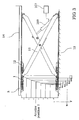
- Fig. 3 shows a side view of a scissor lift to which the locking device according to the invention, for example, is used.
- the locking mechanism 1 is mounted on a first component 11, namely on a laterally displaceable upper end of a scissor bar.
- the detent element 3 is mounted on a second component 12.
- the first component 11, the scissors spar is rotatably connected at its lower end to a third component 13, a foundation or a base plate.
- the second component 12 is a holder which is firmly connected to the detent element 3 and to a fourth component 14, such as a running rail.
- FIG. 3 A corresponding arrangement is in Fig. 3 also shown for the second scissor beam, wherein a laterally displaceable lower end is connected to the locking mechanism and an upper end is rotatably connected to the running rail in connection.
- the scissor lift shown above has from a certain initial height y1 uniform, vertical distances y for locking positions, which can be approached with the lift.
- the locking rails in the horizontal direction must have a different pitch of the teeth. This pitch increases with increasing lift height of the travel rail in the lateral direction, shown by the distances xn, xn + 1, xn + 2, x ..., where xn ⁇ xn + 1 ⁇ xn + 2 ⁇ x ....
- a control unit 107 can be seen, which is in communication with the lifting unit 109.
- the lifting unit is in communication with the two scissor beams of the scissor lift in such a way that, when actuated, it can spread or contract the scissor struts against each other.
- the control unit 107 on the one hand the lifting unit 109 can be controlled, and on the other hand the force element 5 in the locking mechanism 1.
- the control unit 107 controls the lift assembly 109 so as to raise the lift height to a height , which is substantially slightly higher than the locking position 1, but lower than a lifting height, which is composed of the value y1 + 4 ⁇ y.
- the power element 5 is controlled via the control unit, so that the teeth 21, 22 of the locking element in the recesses of the Locking units 41, 42 penetrate, wherein the locking element 2 is rotated out of the housing 5.
- the lifting unit 109 is driven such that the running rail carries out a lowering movement and assumes the locking position 1, wherein the teeth 21 and 22 with the locking units 41 and 42 are firmly engaged.
- the lifting unit 109 is driven so that initially a slight lifting movement is performed, the rail occupies a lifting height which is greater than the height value, consisting of y1 + 3 xy, and is smaller than the height value, which results from y1 + 4 xy, but at least so high that the Verrieglungselement 2 can be converted into a Entarretier ein.
- the force element 5 of the locking mechanism is driven so that the locking element 2 is screwed into the housing 6 and thereby occupies the Entarretierwolf.
- an arresting device according to the invention is provided on the laterally displaceable ends of both scissor struts
- an arrangement is also conceivable in which only one scissor spar is provided with a locking device, and only one guide is attached to the displaceably mounted end of the other scissor spar.
- the locking device may optionally be in communication with the upper slidably mounted end of a scissors spar and a running rail, or be in communication between the lower laterally displaceable end of a scissor spar and a foundation.
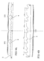
- the Fig. 4A shows a representation of the detent element 3 in a lateral view.
- the Locking mechanism in a first portion 102 in which the locking element is engageable with detents 4, which have substantially equal distances from each other.
- the locking mechanism is in a second portion 103 in which the pitch of the detent elements, that is, the distances between two adjacent detents 4, steadily increase in the longitudinal direction of the detent element 3.
- FIG. 4B an enlarged section of the second portion 103 of the detent element 3.
- Fig. 4B an enlarged section of the second portion 103 of the detent element 3.
- one arm corresponds to the length of a scissor stay, the scissors lift, y1 to an initial height and y to the fixed predefined distance between the rest positions.
Landscapes
- Life Sciences & Earth Sciences (AREA)
- Engineering & Computer Science (AREA)
- Geology (AREA)
- Mechanical Engineering (AREA)
- Structural Engineering (AREA)
- Lock And Its Accessories (AREA)
- Refuge Islands, Traffic Blockers, Or Guard Fence (AREA)
- Power-Operated Mechanisms For Wings (AREA)
- Operating, Guiding And Securing Of Roll- Type Closing Members (AREA)
- Accommodation For Nursing Or Treatment Tables (AREA)
- Pallets (AREA)
- Mutual Connection Of Rods And Tubes (AREA)
Claims (12)
- Dispositif d'arrêt destiné à l'arrêt amovible de composants (11, 12) mobiles l'un par rapport à l'autre, en particulier de dispositifs élévateurs, comportant- un mécanisme de verrouillage (1) susceptible d'être monté sur un premier composant (1) et pourvu d'au moins un élément de verrouillage (2),- un élément (3) à crans susceptible d'être monté sur un second composant (12), l'élément (3) à crans comprenant une multitude de crans (4) réalisés sensiblement identiques,l'élément de verrouillage (2) étant susceptible de venir en engagement avec au moins un cran (4) de façon amovible par coopération de formes et/ou forces dans une multitude de positions d'enclenchement prédéterminées, et- un élément (5) d'application de force pour générer un mouvement relatif entre l'élément de verrouillage (2) et au moins un cran (4), et- dans une zone partielle au moins de l'élément (3) à crans, au moins une première position d'enclenchement, une seconde position d'enclenchement et une troisième position d'enclenchement peuvent être atteintes par l'élément d'enclenchement (2), et au moins une première distance entre la première position d'enclenchement et la seconde position d'enclenchement et une seconde distance entre la seconde position d'enclenchement et la troisième position d'enclenchement présentent différentes longueurs,caractérisé en ce que
l'élément (3) à crans est une crémaillère et les crans (4) sont des dents, l'élément de verrouillage (2) comprenant au moins une dent (10) qui est susceptible de venir en engagement avec les dents de la crémaillère, et/ou l'élément (3) à crans est un rail perforé. - Dispositif d'arrêt selon la revendication 1, dans lequel l'élément (3) à crans comprend une première zone partielle (102) dans laquelle la première distance entre deux crans (4) voisins et la seconde distance entre deux crans (4) voisins sont égales, ainsi qu'une seconde zone partielle (103) dans laquelle la première distance entre des crans (4) voisins et la seconde distance entre des crans (4) voisins sont distinctes, les valeurs en longueur des distances entre deux crans voisins respectifs augmentant ou diminuant en direction longitudinale de l'élément à crans.
- Dispositif d'arrêt selon la revendication 1 ou 2, dans lequel- le premier composant (11) est relié à un troisième composant (13), et- le second composant (12) est relié à un quatrième composant (14), caractérisé en ce que le premier composant (11)- est mobile par rapport au second composant (12) par de premiers mouvements par lesquels l'élément de verrouillage (2) est mobile depuis une première position d'enclenchement jusque dans une seconde position d'enclenchement et/ou jusque dans une troisième position d'enclenchement qui est voisine de la première et/ou de la seconde position d'enclenchement, deux au moins de ces positions d'enclenchement étant situées dans la seconde zone partielle (103), et- de seconds mouvements du troisième composant (13) pouvant être provoqués par rapport au quatrième composant (14), les crans (4) correspondants aux positions d'enclenchement étant distants les uns des autres de telle sorte que les premiers mouvements présentent différentes longueurs et les seconds mouvements présentent constamment les mêmes longueurs, et- les premiers mouvements et les seconds mouvements sont sensiblement perpendiculaires les uns aux autres.
- Dispositif d'arrêt selon l'une des revendications 1 à 3, dans lequel il est prévu une unité de guidage (104) qui est en liaison avec l'élément (3) à crans de telle sorte que l'élément de verrouillage (2) est susceptible de venir s'enclencher avec les crans (4) de l'élément (3) à crans exclusivement dans des positions d'enclenchement prédéterminées.
- Dispositif d'arrêt selon l'une au moins des revendications précédentes, dans lequel l'unité de guidage (104) présente un contour extérieur (105) et l'élément de verrouillage (2) comprend un moyen d'actionnement (106) qui est susceptible de venir en contact avec le contour (105) de l'unité de guidage (104) dans des positions prédéterminées, ce qui permet d'empêcher un contact entre l'élément de verrouillage (2) et l'élément (3) à crans, dans lesdites positions.
- Dispositif d'arrêt selon l'une au moins des revendications précédentes, dans lequel- le mécanisme de verrouillage (1) comprend un boîtier (6) de forme rigide qui est en liaison avec l'élément de verrouillage (2) par une articulation tournante (7), et- une première zone d'extrémité de l'élément d'application de force (5) est en liaison avec l'élément de verrouillage (2), et une seconde zone d'extrémité de l'élément d'application de force (5) est en liaison avec le boîtier (5).
- Dispositif d'arrêt selon l'une au moins des revendications précédentes, dans lequel
l'élément de verrouillage (2) comprend au moins une première dent (21) et une seconde dent (22) qui sont susceptibles de venir en engagement respectivement avec une première unité d'enclenchement (41) et avec une seconde unité d'enclenchement (42), et
l'unité de guidage (104) permet d'empêcher un engagement inopportun de la première dent (21) avec la seconde unité d'enclenchement (42). - Dispositif d'arrêt selon l'une au moins des revendications précédentes, comportant une unité de commande (107) au moyen de laquelle un ensemble d'entraînement (109) destiné à générer un mouvement relatif entre le mécanisme de verrouillage (1) et l'élément (3) à crans est susceptible d'être piloté de telle sorte qu'une première position prédéterminée peut être atteinte par un mouvement dans une première direction, et une fois que cette position est atteinte, une seconde position prédéterminée peut être atteinte par un mouvement dans une seconde direction sensiblement opposée à la première direction.
- Dispositif d'arrêt selon la revendication 8, dans lequel pendant l'opération d'atteindre la seconde position prédéterminée, l'unité de commande (107) est susceptible de piloter l'élément d'application de force (5) de telle sorte que l'élément de verrouillage (2) peut venir en engagement avec un cran (4) de l'élément (3) à crans par coopération de formes et/ou de forces, et ainsi la seconde position prédéterminée correspond à une position d'arrêt.
- Dispositif d'arrêt selon la revendication 8 ou 9, dans lequel, afin de supprimer l'engagement entre l'élément de verrouillage (2) et un cran (4), l'unité de commande (107) pilote l'ensemble d'entraînement (109) de telle sorte qu'un mouvement peut être généré tout d'abord dans la première direction et ensuite un mouvement peut être généré dans une seconde direction qui est sensiblement opposée à la première direction de mouvement, et entre la fin du premier mouvement et le début du second mouvement, l'unité de commande (107) peut piloter l'élément d'application de force (5) de telle sorte que l'engagement par coopération de formes et/ou de forces de l'élément de verrouillage (2) avec un cran (4) de l'élément (3) à crans est amovible.
- Plateforme élévatrice comportant un dispositif d'arrêt selon l'une des revendications précédentes.
- Dispositif élévateur comportant un dispositif d'arrêt selon la revendication 3, caractérisé en ce que- le premier composant (11) est un bras de ciseaux ou de parallélogramme articulé,- le second composant (12) est un support pour l'élément (3) à crans,- le troisième composant (13) est un plancher d'atelier ou une dalle de fondation, et- le quatrième composant (14) est un rail de roulement.
Priority Applications (1)
| Application Number | Priority Date | Filing Date | Title |
|---|---|---|---|
| PL09745462T PL2288570T3 (pl) | 2008-05-16 | 2009-05-15 | Urządzenie unieruchamiające |
Applications Claiming Priority (2)
| Application Number | Priority Date | Filing Date | Title |
|---|---|---|---|
| DE102008024051A DE102008024051A1 (de) | 2008-05-16 | 2008-05-16 | Arretiervorrichtung |
| PCT/DE2009/000700 WO2009138078A1 (fr) | 2008-05-16 | 2009-05-15 | Dispositif d'arrêt |
Publications (2)
| Publication Number | Publication Date |
|---|---|
| EP2288570A1 EP2288570A1 (fr) | 2011-03-02 |
| EP2288570B1 true EP2288570B1 (fr) | 2012-10-03 |
Family
ID=40996708
Family Applications (1)
| Application Number | Title | Priority Date | Filing Date |
|---|---|---|---|
| EP09745462A Not-in-force EP2288570B1 (fr) | 2008-05-16 | 2009-05-15 | Dispositif d'arrêt |
Country Status (10)
| Country | Link |
|---|---|
| US (1) | US8770549B2 (fr) |
| EP (1) | EP2288570B1 (fr) |
| JP (1) | JP2011520725A (fr) |
| KR (1) | KR101645744B1 (fr) |
| CN (1) | CN202080854U (fr) |
| DE (1) | DE102008024051A1 (fr) |
| DK (1) | DK2288570T3 (fr) |
| ES (1) | ES2392671T3 (fr) |
| PL (1) | PL2288570T3 (fr) |
| WO (1) | WO2009138078A1 (fr) |
Families Citing this family (27)
| Publication number | Priority date | Publication date | Assignee | Title |
|---|---|---|---|---|
| DE102007023184A1 (de) * | 2007-05-18 | 2008-11-20 | Maha Maschinenbau Haldenwang Gmbh & Co. Kg | Scherenhebebühne |
| DE102008024051A1 (de) | 2008-05-16 | 2009-11-19 | Maha Maschinenbau Haldenwang Gmbh & Co. Kg | Arretiervorrichtung |
| WO2010129311A1 (fr) * | 2009-05-07 | 2010-11-11 | Vehicle Service Group, Llc | Dispositif de levage pour automobile à liaisons multiples |
| CN101712446B (zh) * | 2009-12-03 | 2012-06-13 | 西安航天动力机械厂 | 一种剪叉式液压升降平台的锁紧装置 |
| FI121993B (fi) * | 2010-02-08 | 2011-07-15 | Fastems Oy Ab | Lastaus- ja purkuasema |
| CN102718171B (zh) * | 2012-06-20 | 2015-02-04 | 资阳晨风电气有限公司 | 机车电器柜用快速升降台机构 |
| TWM461296U (zh) * | 2012-10-25 | 2013-09-01 | Syncmold Entpr Corp | 升降裝置 |
| US9598271B2 (en) * | 2013-09-16 | 2017-03-21 | BendPak, Inc. | Portable automobile lift |
| US10486950B2 (en) * | 2014-07-16 | 2019-11-26 | Gray Manufacturing Company, Inc. | Down stop indicator for vehicle lift |
| US9387869B1 (en) | 2015-04-16 | 2016-07-12 | Aviad Berger | Luggage with mechanically integrated trolley |
| US10246313B2 (en) | 2015-07-31 | 2019-04-02 | Vehicle Service Group, Llc | Precast concrete pit |
| US10227222B2 (en) | 2015-07-31 | 2019-03-12 | Vehicle Service Group, Llc | Precast concrete pit |
| DE102015014280A1 (de) * | 2015-11-06 | 2017-05-11 | Eisenmann Se | Hubsystem zum Anheben und/oder Absenken von Lasten |
| US11192763B2 (en) | 2016-10-27 | 2021-12-07 | BendPak, Inc. | Tilting scissor-lift for vehicles |
| US10745259B2 (en) * | 2016-10-27 | 2020-08-18 | BendPak, Inc. | Scissor-lift for vehicles |
| CN107963570B (zh) * | 2017-01-12 | 2023-08-18 | 天津市先智电气设备有限公司 | 步进支撑式垂直升降装置及控制方法 |
| US11332350B2 (en) * | 2017-05-08 | 2022-05-17 | Nordic Minesteel Technologies Inc. | Telescoping jack for lifting large capacity trucks |
| CN108584777B (zh) * | 2018-06-13 | 2023-07-28 | 苏州市康鼎升降机械有限公司 | 剪叉式液压升降机 |
| CN110203846A (zh) * | 2019-05-23 | 2019-09-06 | 苏州市迅特液压升降机械有限公司 | 一种防坠落液压升降机构及设备 |
| CN110386573A (zh) * | 2019-07-31 | 2019-10-29 | 宁波市加力特机械有限公司 | 一种升降平台车防自降装置 |
| CN111792555A (zh) * | 2019-11-18 | 2020-10-20 | 苏州三鼎升降机有限公司 | 一种具有保护系统的液压升降机 |
| US11584627B2 (en) * | 2020-03-13 | 2023-02-21 | Bosch Automotive Service Solutions Inc. | Safety catch system |
| DE102021112897B4 (de) | 2020-05-20 | 2023-12-14 | Adient Us Llc | Einstellmechanismus für einen fahrzeugsitz, sowie kopfstütze für einen fahrzeugsitz |
| CN112174026A (zh) * | 2020-10-09 | 2021-01-05 | 中国十七冶集团有限公司 | 一种场馆大型构件用顶升装置及顶升方法 |
| CN214456517U (zh) * | 2020-12-18 | 2021-10-22 | 江西洪都航空工业集团有限责任公司 | 一种升降平台 |
| CN113928771B (zh) * | 2021-12-17 | 2022-03-18 | 苏州牧星智能科技有限公司 | 顶升装置的自锁机构、顶升装置及搬运机器人 |
| US12427907B2 (en) | 2023-12-05 | 2025-09-30 | Brian Christopher Alder | Leveling mount for a vehicle mounted tent |
Family Cites Families (21)
| Publication number | Priority date | Publication date | Assignee | Title |
|---|---|---|---|---|
| US1545223A (en) * | 1925-04-01 | 1925-07-07 | Westrate Matthew | Jacks |
| US2361690A (en) * | 1941-12-15 | 1944-10-31 | Alphonse W Hunz | Lifting jack |
| US2555350A (en) * | 1946-08-22 | 1951-06-05 | Roy D Lloyd | Mechanical folding jack |
| US2739849A (en) * | 1950-09-01 | 1956-03-27 | Lynn John | Height adjustable stands |
| US2611579A (en) * | 1951-05-28 | 1952-09-23 | Miller Mfg Co Inc | Vehicle lift |
| US3317004A (en) * | 1966-01-14 | 1967-05-02 | Dover Corp | Safety device for a vehicle lift |
| US3334866A (en) * | 1966-05-10 | 1967-08-08 | Bergamino Anthony | Traveling step-by-step power jack |
| US3704860A (en) * | 1968-01-25 | 1972-12-05 | John M Krapu | Wedging and prying tool |
| DE2745639C3 (de) * | 1977-10-11 | 1980-12-04 | Robert Kahl, Rokado, 4755 Holzwickede | Vorrichtung zum Verstellen eines schwenkbaren Bettrahmenteils |
| US4899987A (en) * | 1988-12-08 | 1990-02-13 | Hein-Werner Corporation | Vehicle scissor lift |
| US5004075A (en) * | 1989-08-30 | 1991-04-02 | Anthony Ascenzo | Lifting device for objects |
| US5050844A (en) * | 1989-10-05 | 1991-09-24 | Vbm Corporation | Lift assembly |
| US6601430B2 (en) * | 2001-10-09 | 2003-08-05 | Delaware Capital Formation, Inc. | Jack with elevatable platform |
| JP4359443B2 (ja) | 2003-04-18 | 2009-11-04 | 株式会社スギヤス | 車両整備用リフト |
| KR200320302Y1 (ko) | 2003-04-28 | 2003-07-22 | 주식회사 한솔엔지니어링 | 자동차 정비용 리프트 |
| CN100560405C (zh) * | 2006-01-26 | 2009-11-18 | 浙江双友物流器械股份有限公司 | 改进结构的撑货器 |
| DE202007004524U1 (de) * | 2007-03-28 | 2008-08-07 | Brose Fahrzeugteile Gmbh & Co. Kommanditgesellschaft, Coburg | Arretiervorrichtung für einen Kraftfahrzeugsitz |
| DE102007023184A1 (de) * | 2007-05-18 | 2008-11-20 | Maha Maschinenbau Haldenwang Gmbh & Co. Kg | Scherenhebebühne |
| DE202007014662U1 (de) * | 2007-10-19 | 2007-12-20 | Maha Maschinenbau Haldenwang Gmbh & Co. Kg | Verriegelungsvorrichtung |
| DE102008024051A1 (de) * | 2008-05-16 | 2009-11-19 | Maha Maschinenbau Haldenwang Gmbh & Co. Kg | Arretiervorrichtung |
| DE102012006028A1 (de) * | 2012-03-27 | 2013-10-02 | Rofa Industrial Automation Ag | Scherenhubtisch |
-
2008
- 2008-05-16 DE DE102008024051A patent/DE102008024051A1/de not_active Withdrawn
-
2009
- 2009-05-15 KR KR1020107028056A patent/KR101645744B1/ko not_active Expired - Fee Related
- 2009-05-15 DK DK09745462.3T patent/DK2288570T3/da active
- 2009-05-15 CN CN2009901003781U patent/CN202080854U/zh not_active Expired - Fee Related
- 2009-05-15 PL PL09745462T patent/PL2288570T3/pl unknown
- 2009-05-15 JP JP2011508793A patent/JP2011520725A/ja not_active Withdrawn
- 2009-05-15 WO PCT/DE2009/000700 patent/WO2009138078A1/fr not_active Ceased
- 2009-05-15 ES ES09745462T patent/ES2392671T3/es active Active
- 2009-05-15 EP EP09745462A patent/EP2288570B1/fr not_active Not-in-force
-
2010
- 2010-11-15 US US12/946,564 patent/US8770549B2/en not_active Expired - Fee Related
Also Published As
| Publication number | Publication date |
|---|---|
| PL2288570T3 (pl) | 2013-03-29 |
| DE102008024051A1 (de) | 2009-11-19 |
| WO2009138078A1 (fr) | 2009-11-19 |
| JP2011520725A (ja) | 2011-07-21 |
| US20110278517A1 (en) | 2011-11-17 |
| KR101645744B1 (ko) | 2016-08-04 |
| KR20110018900A (ko) | 2011-02-24 |
| US8770549B2 (en) | 2014-07-08 |
| ES2392671T3 (es) | 2012-12-12 |
| DK2288570T3 (da) | 2013-01-21 |
| CN202080854U (zh) | 2011-12-21 |
| EP2288570A1 (fr) | 2011-03-02 |
Similar Documents
| Publication | Publication Date | Title |
|---|---|---|
| EP2288570B1 (fr) | Dispositif d'arrêt | |
| DE102018211055B4 (de) | Arretier- und Kontaktierungssystem zum elektrischen Verbinden eines Bordnetzes eines Kraftfahrzeugs mit einem entnehmbaren Fahrzeugsitz oder einer Sitzanlage | |
| EP2158152B1 (fr) | Dispositif de levage articulé | |
| DE69401601T2 (de) | Lageeinstellungsvorrichtung für Kraftfahrzeugsitze | |
| EP0017765B1 (fr) | Dispositif de levage hydraulique | |
| EP1001888B1 (fr) | Dispositif de verrouillage pour sièges, en particulier pour sièges de véhicules à moteur | |
| EP3389446B1 (fr) | Corps de tiroir avec un dispositif pour la fixation détachable d'un parement frontal et procédé de montage et de démontage d'un parement frontal | |
| EP2729324A1 (fr) | Siège de véhicule à dossier rabattable pouvant être déplacé vers l'avant dans sa glissière longitudinale | |
| DE10241441A1 (de) | Fahrzeugsitz-Gestell und Sitz mit einem solchen Gestell | |
| DE2844647C2 (de) | Längsverstellvorrichtung für einen Fahrzeugsitz, insbesondere einen Kraftfahrzeugsitz | |
| EP2487130A1 (fr) | Protection statique contre les chutes pour un ascenseur à plateforme et ascenseur à plateforme en étant équipé | |
| DE202004001916U1 (de) | Mechanismus für ein Schiebedach | |
| EP1275541A1 (fr) | Module, spécialement module coulissant pour véhicule | |
| EP0733021B1 (fr) | Fleche telescopique a verin hydraulique a plusieurs etages | |
| DE102014214184A1 (de) | Längseinsteller für einen Fahrzeugsitz und Fahrzeugsitz | |
| DE4102312C2 (de) | Sitzschiene für Fahrzeugsitze, insbesondere für Kraftfahrzeugsitze | |
| EP3636104A2 (fr) | Dispositif d'accouplement pour le guidage de coulisse | |
| AT518917B1 (de) | Absturzsicherung | |
| EP3089890B1 (fr) | Recouvrement d'un compartiment à bagages d`un véhicule automobile | |
| DE102004025504B4 (de) | Verriegelung für einen Sitzlängsversteller | |
| WO2011131162A1 (fr) | Dispositif de traction d'un dispositif de rétraction chirurgical | |
| DE2208867A1 (de) | Sitzanordnung mit mitteln zur arretierung der in ihrer neigung verstellbaren rueckenlehne, insbesondere fuer ein kraftfahrzeug | |
| EP2859869B1 (fr) | Dispositif destiné à la liaison coulissante d'un siège passager à une structure de véhicule | |
| DE102010015737A1 (de) | Verriegelungseinrichtung für einen Fahrzeugsitz | |
| DE102005028961B4 (de) | Überrollschutzsystem mit Synchronisationseinrichtung für ein Kraftfahrzeug, insbesondere für ein Cabriolet |
Legal Events
| Date | Code | Title | Description |
|---|---|---|---|
| PUAI | Public reference made under article 153(3) epc to a published international application that has entered the european phase |
Free format text: ORIGINAL CODE: 0009012 |
|
| 17P | Request for examination filed |
Effective date: 20101216 |
|
| AK | Designated contracting states |
Kind code of ref document: A1 Designated state(s): AT BE BG CH CY CZ DE DK EE ES FI FR GB GR HR HU IE IS IT LI LT LU LV MC MK MT NL NO PL PT RO SE SI SK TR |
|
| AX | Request for extension of the european patent |
Extension state: AL BA RS |
|
| DAX | Request for extension of the european patent (deleted) | ||
| GRAP | Despatch of communication of intention to grant a patent |
Free format text: ORIGINAL CODE: EPIDOSNIGR1 |
|
| GRAS | Grant fee paid |
Free format text: ORIGINAL CODE: EPIDOSNIGR3 |
|
| GRAA | (expected) grant |
Free format text: ORIGINAL CODE: 0009210 |
|
| AK | Designated contracting states |
Kind code of ref document: B1 Designated state(s): AT BE BG CH CY CZ DE DK EE ES FI FR GB GR HR HU IE IS IT LI LT LU LV MC MK MT NL NO PL PT RO SE SI SK TR |
|
| REG | Reference to a national code |
Ref country code: GB Ref legal event code: FG4D Free format text: NOT ENGLISH |
|
| REG | Reference to a national code |
Ref country code: AT Ref legal event code: REF Ref document number: 577887 Country of ref document: AT Kind code of ref document: T Effective date: 20121015 Ref country code: CH Ref legal event code: EP |
|
| REG | Reference to a national code |
Ref country code: IE Ref legal event code: FG4D Free format text: LANGUAGE OF EP DOCUMENT: GERMAN |
|
| REG | Reference to a national code |
Ref country code: DE Ref legal event code: R096 Ref document number: 502009004966 Country of ref document: DE Effective date: 20121129 |
|
| REG | Reference to a national code |
Ref country code: ES Ref legal event code: FG2A Ref document number: 2392671 Country of ref document: ES Kind code of ref document: T3 Effective date: 20121212 |
|
| REG | Reference to a national code |
Ref country code: DK Ref legal event code: T3 |
|
| PG25 | Lapsed in a contracting state [announced via postgrant information from national office to epo] |
Ref country code: SI Free format text: LAPSE BECAUSE OF FAILURE TO SUBMIT A TRANSLATION OF THE DESCRIPTION OR TO PAY THE FEE WITHIN THE PRESCRIBED TIME-LIMIT Effective date: 20121003 |
|
| REG | Reference to a national code |
Ref country code: NL Ref legal event code: VDEP Effective date: 20121003 |
|
| REG | Reference to a national code |
Ref country code: LT Ref legal event code: MG4D |
|
| REG | Reference to a national code |
Ref country code: PL Ref legal event code: T3 |
|
| PG25 | Lapsed in a contracting state [announced via postgrant information from national office to epo] |
Ref country code: LT Free format text: LAPSE BECAUSE OF FAILURE TO SUBMIT A TRANSLATION OF THE DESCRIPTION OR TO PAY THE FEE WITHIN THE PRESCRIBED TIME-LIMIT Effective date: 20121003 Ref country code: IS Free format text: LAPSE BECAUSE OF FAILURE TO SUBMIT A TRANSLATION OF THE DESCRIPTION OR TO PAY THE FEE WITHIN THE PRESCRIBED TIME-LIMIT Effective date: 20130203 Ref country code: NO Free format text: LAPSE BECAUSE OF FAILURE TO SUBMIT A TRANSLATION OF THE DESCRIPTION OR TO PAY THE FEE WITHIN THE PRESCRIBED TIME-LIMIT Effective date: 20130103 Ref country code: SE Free format text: LAPSE BECAUSE OF FAILURE TO SUBMIT A TRANSLATION OF THE DESCRIPTION OR TO PAY THE FEE WITHIN THE PRESCRIBED TIME-LIMIT Effective date: 20121003 Ref country code: FI Free format text: LAPSE BECAUSE OF FAILURE TO SUBMIT A TRANSLATION OF THE DESCRIPTION OR TO PAY THE FEE WITHIN THE PRESCRIBED TIME-LIMIT Effective date: 20121003 Ref country code: NL Free format text: LAPSE BECAUSE OF FAILURE TO SUBMIT A TRANSLATION OF THE DESCRIPTION OR TO PAY THE FEE WITHIN THE PRESCRIBED TIME-LIMIT Effective date: 20121003 Ref country code: HR Free format text: LAPSE BECAUSE OF FAILURE TO SUBMIT A TRANSLATION OF THE DESCRIPTION OR TO PAY THE FEE WITHIN THE PRESCRIBED TIME-LIMIT Effective date: 20121003 |
|
| PG25 | Lapsed in a contracting state [announced via postgrant information from national office to epo] |
Ref country code: LV Free format text: LAPSE BECAUSE OF FAILURE TO SUBMIT A TRANSLATION OF THE DESCRIPTION OR TO PAY THE FEE WITHIN THE PRESCRIBED TIME-LIMIT Effective date: 20121003 Ref country code: PT Free format text: LAPSE BECAUSE OF FAILURE TO SUBMIT A TRANSLATION OF THE DESCRIPTION OR TO PAY THE FEE WITHIN THE PRESCRIBED TIME-LIMIT Effective date: 20130204 Ref country code: GR Free format text: LAPSE BECAUSE OF FAILURE TO SUBMIT A TRANSLATION OF THE DESCRIPTION OR TO PAY THE FEE WITHIN THE PRESCRIBED TIME-LIMIT Effective date: 20130104 |
|
| PG25 | Lapsed in a contracting state [announced via postgrant information from national office to epo] |
Ref country code: EE Free format text: LAPSE BECAUSE OF FAILURE TO SUBMIT A TRANSLATION OF THE DESCRIPTION OR TO PAY THE FEE WITHIN THE PRESCRIBED TIME-LIMIT Effective date: 20121003 Ref country code: SK Free format text: LAPSE BECAUSE OF FAILURE TO SUBMIT A TRANSLATION OF THE DESCRIPTION OR TO PAY THE FEE WITHIN THE PRESCRIBED TIME-LIMIT Effective date: 20121003 Ref country code: CZ Free format text: LAPSE BECAUSE OF FAILURE TO SUBMIT A TRANSLATION OF THE DESCRIPTION OR TO PAY THE FEE WITHIN THE PRESCRIBED TIME-LIMIT Effective date: 20121003 Ref country code: BG Free format text: LAPSE BECAUSE OF FAILURE TO SUBMIT A TRANSLATION OF THE DESCRIPTION OR TO PAY THE FEE WITHIN THE PRESCRIBED TIME-LIMIT Effective date: 20130103 |
|
| PLBE | No opposition filed within time limit |
Free format text: ORIGINAL CODE: 0009261 |
|
| STAA | Information on the status of an ep patent application or granted ep patent |
Free format text: STATUS: NO OPPOSITION FILED WITHIN TIME LIMIT |
|
| PG25 | Lapsed in a contracting state [announced via postgrant information from national office to epo] |
Ref country code: RO Free format text: LAPSE BECAUSE OF FAILURE TO SUBMIT A TRANSLATION OF THE DESCRIPTION OR TO PAY THE FEE WITHIN THE PRESCRIBED TIME-LIMIT Effective date: 20121003 |
|
| 26N | No opposition filed |
Effective date: 20130704 |
|
| REG | Reference to a national code |
Ref country code: DE Ref legal event code: R097 Ref document number: 502009004966 Country of ref document: DE Effective date: 20130704 |
|
| PG25 | Lapsed in a contracting state [announced via postgrant information from national office to epo] |
Ref country code: CY Free format text: LAPSE BECAUSE OF FAILURE TO SUBMIT A TRANSLATION OF THE DESCRIPTION OR TO PAY THE FEE WITHIN THE PRESCRIBED TIME-LIMIT Effective date: 20121003 |
|
| BERE | Be: lapsed |
Owner name: MAHA MASCHINENBAU HALDENWANG G.M.B.H. & CO. KG Effective date: 20130531 |
|
| PG25 | Lapsed in a contracting state [announced via postgrant information from national office to epo] |
Ref country code: MC Free format text: LAPSE BECAUSE OF FAILURE TO SUBMIT A TRANSLATION OF THE DESCRIPTION OR TO PAY THE FEE WITHIN THE PRESCRIBED TIME-LIMIT Effective date: 20121003 |
|
| REG | Reference to a national code |
Ref country code: CH Ref legal event code: PL |
|
| GBPC | Gb: european patent ceased through non-payment of renewal fee |
Effective date: 20130515 |
|
| PG25 | Lapsed in a contracting state [announced via postgrant information from national office to epo] |
Ref country code: CH Free format text: LAPSE BECAUSE OF NON-PAYMENT OF DUE FEES Effective date: 20130531 Ref country code: LI Free format text: LAPSE BECAUSE OF NON-PAYMENT OF DUE FEES Effective date: 20130531 |
|
| REG | Reference to a national code |
Ref country code: IE Ref legal event code: MM4A |
|
| PG25 | Lapsed in a contracting state [announced via postgrant information from national office to epo] |
Ref country code: BE Free format text: LAPSE BECAUSE OF NON-PAYMENT OF DUE FEES Effective date: 20130531 |
|
| REG | Reference to a national code |
Ref country code: FR Ref legal event code: ST Effective date: 20140131 |
|
| PG25 | Lapsed in a contracting state [announced via postgrant information from national office to epo] |
Ref country code: IE Free format text: LAPSE BECAUSE OF NON-PAYMENT OF DUE FEES Effective date: 20130515 Ref country code: GB Free format text: LAPSE BECAUSE OF NON-PAYMENT OF DUE FEES Effective date: 20130515 |
|
| PG25 | Lapsed in a contracting state [announced via postgrant information from national office to epo] |
Ref country code: FR Free format text: LAPSE BECAUSE OF NON-PAYMENT OF DUE FEES Effective date: 20130531 |
|
| PG25 | Lapsed in a contracting state [announced via postgrant information from national office to epo] |
Ref country code: MT Free format text: LAPSE BECAUSE OF FAILURE TO SUBMIT A TRANSLATION OF THE DESCRIPTION OR TO PAY THE FEE WITHIN THE PRESCRIBED TIME-LIMIT Effective date: 20121003 |
|
| PG25 | Lapsed in a contracting state [announced via postgrant information from national office to epo] |
Ref country code: TR Free format text: LAPSE BECAUSE OF FAILURE TO SUBMIT A TRANSLATION OF THE DESCRIPTION OR TO PAY THE FEE WITHIN THE PRESCRIBED TIME-LIMIT Effective date: 20121003 |
|
| REG | Reference to a national code |
Ref country code: AT Ref legal event code: MM01 Ref document number: 577887 Country of ref document: AT Kind code of ref document: T Effective date: 20140515 |
|
| PG25 | Lapsed in a contracting state [announced via postgrant information from national office to epo] |
Ref country code: MK Free format text: LAPSE BECAUSE OF FAILURE TO SUBMIT A TRANSLATION OF THE DESCRIPTION OR TO PAY THE FEE WITHIN THE PRESCRIBED TIME-LIMIT Effective date: 20121003 Ref country code: LU Free format text: LAPSE BECAUSE OF NON-PAYMENT OF DUE FEES Effective date: 20130515 Ref country code: HU Free format text: LAPSE BECAUSE OF FAILURE TO SUBMIT A TRANSLATION OF THE DESCRIPTION OR TO PAY THE FEE WITHIN THE PRESCRIBED TIME-LIMIT; INVALID AB INITIO Effective date: 20090515 |
|
| PG25 | Lapsed in a contracting state [announced via postgrant information from national office to epo] |
Ref country code: AT Free format text: LAPSE BECAUSE OF NON-PAYMENT OF DUE FEES Effective date: 20140515 |
|
| PGFP | Annual fee paid to national office [announced via postgrant information from national office to epo] |
Ref country code: DE Payment date: 20170531 Year of fee payment: 9 Ref country code: DK Payment date: 20170524 Year of fee payment: 9 |
|
| PGFP | Annual fee paid to national office [announced via postgrant information from national office to epo] |
Ref country code: ES Payment date: 20170601 Year of fee payment: 9 Ref country code: PL Payment date: 20170508 Year of fee payment: 9 Ref country code: IT Payment date: 20170524 Year of fee payment: 9 |
|
| REG | Reference to a national code |
Ref country code: DE Ref legal event code: R119 Ref document number: 502009004966 Country of ref document: DE |
|
| REG | Reference to a national code |
Ref country code: DK Ref legal event code: EBP Effective date: 20180531 |
|
| PG25 | Lapsed in a contracting state [announced via postgrant information from national office to epo] |
Ref country code: IT Free format text: LAPSE BECAUSE OF NON-PAYMENT OF DUE FEES Effective date: 20180515 Ref country code: DE Free format text: LAPSE BECAUSE OF NON-PAYMENT OF DUE FEES Effective date: 20181201 |
|
| PG25 | Lapsed in a contracting state [announced via postgrant information from national office to epo] |
Ref country code: DK Free format text: LAPSE BECAUSE OF NON-PAYMENT OF DUE FEES Effective date: 20180531 |
|
| REG | Reference to a national code |
Ref country code: ES Ref legal event code: FD2A Effective date: 20190913 |
|
| PG25 | Lapsed in a contracting state [announced via postgrant information from national office to epo] |
Ref country code: ES Free format text: LAPSE BECAUSE OF NON-PAYMENT OF DUE FEES Effective date: 20180516 |
|
| PG25 | Lapsed in a contracting state [announced via postgrant information from national office to epo] |
Ref country code: PL Free format text: LAPSE BECAUSE OF NON-PAYMENT OF DUE FEES Effective date: 20180515 |