EP2288570B1 - Fixing device - Google Patents
Fixing device Download PDFInfo
- Publication number
- EP2288570B1 EP2288570B1 EP09745462A EP09745462A EP2288570B1 EP 2288570 B1 EP2288570 B1 EP 2288570B1 EP 09745462 A EP09745462 A EP 09745462A EP 09745462 A EP09745462 A EP 09745462A EP 2288570 B1 EP2288570 B1 EP 2288570B1
- Authority
- EP
- European Patent Office
- Prior art keywords
- locking
- catch
- component
- fixing device
- catching
- Prior art date
- Legal status (The legal status is an assumption and is not a legal conclusion. Google has not performed a legal analysis and makes no representation as to the accuracy of the status listed.)
- Not-in-force
Links
Images


Classifications
-
- B—PERFORMING OPERATIONS; TRANSPORTING
- B66—HOISTING; LIFTING; HAULING
- B66F—HOISTING, LIFTING, HAULING OR PUSHING, NOT OTHERWISE PROVIDED FOR, e.g. DEVICES WHICH APPLY A LIFTING OR PUSHING FORCE DIRECTLY TO THE SURFACE OF A LOAD
- B66F7/00—Lifting frames, e.g. for lifting vehicles; Platform lifts
- B66F7/06—Lifting frames, e.g. for lifting vehicles; Platform lifts with platforms supported by levers for vertical movement
- B66F7/08—Lifting frames, e.g. for lifting vehicles; Platform lifts with platforms supported by levers for vertical movement hydraulically or pneumatically operated
-
- B—PERFORMING OPERATIONS; TRANSPORTING
- B66—HOISTING; LIFTING; HAULING
- B66F—HOISTING, LIFTING, HAULING OR PUSHING, NOT OTHERWISE PROVIDED FOR, e.g. DEVICES WHICH APPLY A LIFTING OR PUSHING FORCE DIRECTLY TO THE SURFACE OF A LOAD
- B66F7/00—Lifting frames, e.g. for lifting vehicles; Platform lifts
- B66F7/06—Lifting frames, e.g. for lifting vehicles; Platform lifts with platforms supported by levers for vertical movement
- B66F7/065—Scissor linkages, i.e. X-configuration
-
- B—PERFORMING OPERATIONS; TRANSPORTING
- B66—HOISTING; LIFTING; HAULING
- B66F—HOISTING, LIFTING, HAULING OR PUSHING, NOT OTHERWISE PROVIDED FOR, e.g. DEVICES WHICH APPLY A LIFTING OR PUSHING FORCE DIRECTLY TO THE SURFACE OF A LOAD
- B66F7/00—Lifting frames, e.g. for lifting vehicles; Platform lifts
- B66F7/28—Constructional details, e.g. end stops, pivoting supporting members, sliding runners adjustable to load dimensions
-
- Y—GENERAL TAGGING OF NEW TECHNOLOGICAL DEVELOPMENTS; GENERAL TAGGING OF CROSS-SECTIONAL TECHNOLOGIES SPANNING OVER SEVERAL SECTIONS OF THE IPC; TECHNICAL SUBJECTS COVERED BY FORMER USPC CROSS-REFERENCE ART COLLECTIONS [XRACs] AND DIGESTS
- Y10—TECHNICAL SUBJECTS COVERED BY FORMER USPC
- Y10T—TECHNICAL SUBJECTS COVERED BY FORMER US CLASSIFICATION
- Y10T29/00—Metal working
- Y10T29/49—Method of mechanical manufacture
- Y10T29/49826—Assembling or joining
- Y10T29/49947—Assembling or joining by applying separate fastener
-
- Y—GENERAL TAGGING OF NEW TECHNOLOGICAL DEVELOPMENTS; GENERAL TAGGING OF CROSS-SECTIONAL TECHNOLOGIES SPANNING OVER SEVERAL SECTIONS OF THE IPC; TECHNICAL SUBJECTS COVERED BY FORMER USPC CROSS-REFERENCE ART COLLECTIONS [XRACs] AND DIGESTS
- Y10—TECHNICAL SUBJECTS COVERED BY FORMER USPC
- Y10T—TECHNICAL SUBJECTS COVERED BY FORMER US CLASSIFICATION
- Y10T403/00—Joints and connections
- Y10T403/32—Articulated members
- Y10T403/32254—Lockable at fixed position
Definitions
- the invention relates to a locking device for releasably locking relatively movable components, in particular for use on lifting devices, with the two mutually linearly movable parts can be releasably locked, which also ensures that an unwanted entanglement of the locking device is excluded and thus blocking or Failure of the apparatus, on which the locking device is provided, is prevented.
- a latch mechanism is generally displaced relative to a rack, wherein the latch mechanism can be brought into engagement with the rack when a latching position is reached.
- a uniform pitch of the teeth on the rack offers a variety equidistant detent positions in which the latch mechanism can be locked with the rack.
- a scissor beam is connected at its upper end rotatably connected to a running rail and mounted with its lower end longitudinally displaceable on a foundation, and the second scissor stay with its lower end rotatably connected to the foundation and with its upper end longitudinally slidably connected to a running rail.
- the slidably mounted ends of the scissor struts are connected to a pawl element which is displaceable along a rack.
- this type of lift stage has a kinematics in which the linearly guided end of the scissor struts moves during a lifting or lowering movement of the scissor lift on a curved path. It follows that in a magnitude same lateral displacement of the pawl mechanism from along detent position to the next detent position in terms of magnitude ever smaller stroke occurs from one locking position to the next locking position of the lift. Due to the large number of latching possibilities, it is difficult to latch the lift in predetermined, equidistant stroke positions.
- US-A-3,317,004 describes a safety device with which an unintentional lowering of a vehicle lift should be avoided.
- U.S. Pat. No. 5,050,844 describes a lifting device for large vehicles with a first and a second platform. A locking device holds the two platforms in the raised state.
- the invention has the object, so on form a device of the structure described above, that in a particularly simple manner equidistant, predetermined latching positions of the lift can be ensured.
- the invention teaches a locking device for releasably locking relatively movable components, in particular lifting devices comprising a lockable to a first component locking mechanism, with at least one locking unit, and a second component mountable locking element, wherein the locking element a plurality of substantially identically designed detents may have, wherein the locking element in a plurality of predetermined detent positions with at least one detent releasably, formally and / or can be brought into frictional engagement.
- the locking device may further comprise a force element for generating a relative movement between the locking element and at least one catch.
- At least a first detent position, a second detent position and a third detent position with the locking element can be approachable in at least a portion of the locking element, wherein at least a first distance between the first detent position and the second detent position and a second distance between the second detent position and the third Detent position, different lengths may have.
- the number of possible locking positions can be reduced to a smaller number of predetermined locking positions in a particularly simple manner, whereby the time required to find the equidistant locking positions is significantly reduced. It is well known to those skilled in the art that by corresponding numbering of the latching positions at least a first distance between the first latching position and the third latching position and a second distance between the second latching position and the first latching position can have different lengths.
- the latching element may have a first partial area in which the first distance between two adjacent detents and the second distance between two adjacent detents is the same, and have a second partial area in which the first distance between two adjacent detents and the second distance between two adjacent latches is different, wherein the length values of the distances between each two adjacent notches in the longitudinal direction of the detent element continuously, steadily, abruptly and / or discontinuously increase or decrease.
- the first component may be connected to a third component
- the second component may be connected to a fourth component, wherein the first component by first movements in which the locking element from a first detent position to a second detent position and / or to a third detent position is adjacent to the first and / or second detent position, wherein at least two of these detent positions are located in the second portion, is displaceable relative to the second component, and second movements of the third component relative to the fourth component can be effected.
- the detents corresponding to the detent positions can be spaced from one another such that the first movements have different lengths and the second movements always have the same lengths, wherein the first movements and the second movements are substantially perpendicular to each other.
- a guide unit may be provided which is in communication with the latching element in such a way that the latching element can be latched exclusively in predetermined latching positions with the detents of the latching element.
- the guide unit may have an outer contour and the locking element having an actuating means which may be in predetermined positions with the contour of the guide unit in contact, whereby in this position a contact between the locking element and the latch member can be prevented.
- the force element may be a hydraulic cylinder, a stepper motor, an electromagnetic actuator, a spring element and / or a pneumatic cylinder.
- the locking mechanism may comprise a dimensionally stable housing which is connected to the locking element via a Rotary joint may be in communication, wherein a first end portion of the force element may be in communication with the locking element, and a second end portion of the force element may be in communication with a housing.
- the locking element may be a rack and the detents teeth, wherein the locking element may have at least one tooth which is engageable with the teeth of the rack engaged.
- the locking element may be a perforated rail.
- the locking element can have at least one first tooth and / or at least one second tooth, which can each be brought into engagement with a first latching unit and / or a second latching unit, wherein the guide unit prevents undesired engagement of the first tooth with the second latching unit ,
- a control unit may be provided, with which a drive unit for generating a relative movement, between the locking mechanism and the latching element, such that a first predetermined position can be reached by a movement in a first direction and after reaching this position by a movement in a second direction that is substantially opposite the first direction, a second predetermined position is achievable.
- control unit can actuate the force element in such a way that the locking element can be brought into positive and / or non-positive engagement with a detent of the detent element and thereby corresponds to the second predetermined position of a detent position.
- a force element actuate the locking element such that the locking element with a detent of the locking element form and / or non-positively engageable and thereby corresponds to the second predetermined position of a locking position.
- the control unit can actuate the drive unit in such a way that first movement in the first direction can be generated and subsequently movement in a second direction can be generated, which is essentially opposite to the first direction of movement.
- the force element can be controlled in such a way that the positive and / or non-positive engagement of the locking element with a detent of the detent element is achieved becomes.
- a locking device 1 which has a dimensionally stable housing 6, in which a locking element 2 (not visible) is introduced.
- the locking element 2 can be brought into engagement with a detent element 3.
- the detent element 3 has identically designed detents 4, which each have a first detent unit 41 and a second detent unit 42.
- On a side surface 110 of the detent element 3, a guide unit 104 is provided which has flat elevations 108. The distances between the elevations 108 essentially correspond to the distances between the detents 4.
- the guide unit 104 is aligned with the detent element 3 such that its elevations 108 laterally cover the respectively second detent unit 42 of the detents 4. Furthermore, in Fig.
- the actuating means 106 which is arranged on the locking element 2 and is in communication with the guide unit 104. During a lateral movement of the locking mechanism 1 along the detent element in the direction of the arrow L, the actuating means 106 comes into contact with the contour 105 of the guide unit 104 in the region of the elevations 108. This contact blocks this Actuator 106, the locking element 2 and thereby does not allow an extension of the locking element 2.
- Fig. 2 is a side sectional view shown in the longitudinal direction by the locking device.
- a force element 5 is provided, in the form of a hydraulic or pneumatic cylinder.
- the force element is connected in a first end region via a rotary joint 9 with the housing 6 and connected in a second end region via a rotary joint 8 with the locking element 2.
- the locking element 2 is rotatably mounted in the housing 6. By actuation of the force element 5, the locking element 2 can rotate about the axis of rotation 7 and thereby moved into the housing 6 or from the housing 6, so as to be transferred into a locking or Entarretier position.
- the locking element has two teeth, a first tooth 21 and a second tooth 22, which are in a locking position with a respective first latching unit 41 and a second latching unit 42 of a detent engaged.
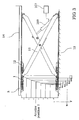
- Fig. 3 shows a side view of a scissor lift to which the locking device according to the invention, for example, is used.
- the locking mechanism 1 is mounted on a first component 11, namely on a laterally displaceable upper end of a scissor bar.
- the detent element 3 is mounted on a second component 12.
- the first component 11, the scissors spar is rotatably connected at its lower end to a third component 13, a foundation or a base plate.
- the second component 12 is a holder which is firmly connected to the detent element 3 and to a fourth component 14, such as a running rail.
- FIG. 3 A corresponding arrangement is in Fig. 3 also shown for the second scissor beam, wherein a laterally displaceable lower end is connected to the locking mechanism and an upper end is rotatably connected to the running rail in connection.
- the scissor lift shown above has from a certain initial height y1 uniform, vertical distances y for locking positions, which can be approached with the lift.
- the locking rails in the horizontal direction must have a different pitch of the teeth. This pitch increases with increasing lift height of the travel rail in the lateral direction, shown by the distances xn, xn + 1, xn + 2, x ..., where xn ⁇ xn + 1 ⁇ xn + 2 ⁇ x ....
- a control unit 107 can be seen, which is in communication with the lifting unit 109.
- the lifting unit is in communication with the two scissor beams of the scissor lift in such a way that, when actuated, it can spread or contract the scissor struts against each other.
- the control unit 107 on the one hand the lifting unit 109 can be controlled, and on the other hand the force element 5 in the locking mechanism 1.
- the control unit 107 controls the lift assembly 109 so as to raise the lift height to a height , which is substantially slightly higher than the locking position 1, but lower than a lifting height, which is composed of the value y1 + 4 ⁇ y.
- the power element 5 is controlled via the control unit, so that the teeth 21, 22 of the locking element in the recesses of the Locking units 41, 42 penetrate, wherein the locking element 2 is rotated out of the housing 5.
- the lifting unit 109 is driven such that the running rail carries out a lowering movement and assumes the locking position 1, wherein the teeth 21 and 22 with the locking units 41 and 42 are firmly engaged.
- the lifting unit 109 is driven so that initially a slight lifting movement is performed, the rail occupies a lifting height which is greater than the height value, consisting of y1 + 3 xy, and is smaller than the height value, which results from y1 + 4 xy, but at least so high that the Verrieglungselement 2 can be converted into a Entarretier ein.
- the force element 5 of the locking mechanism is driven so that the locking element 2 is screwed into the housing 6 and thereby occupies the Entarretierwolf.
- an arresting device according to the invention is provided on the laterally displaceable ends of both scissor struts
- an arrangement is also conceivable in which only one scissor spar is provided with a locking device, and only one guide is attached to the displaceably mounted end of the other scissor spar.
- the locking device may optionally be in communication with the upper slidably mounted end of a scissors spar and a running rail, or be in communication between the lower laterally displaceable end of a scissor spar and a foundation.
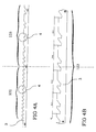
- the Fig. 4A shows a representation of the detent element 3 in a lateral view.
- the Locking mechanism in a first portion 102 in which the locking element is engageable with detents 4, which have substantially equal distances from each other.
- the locking mechanism is in a second portion 103 in which the pitch of the detent elements, that is, the distances between two adjacent detents 4, steadily increase in the longitudinal direction of the detent element 3.
- FIG. 4B an enlarged section of the second portion 103 of the detent element 3.
- Fig. 4B an enlarged section of the second portion 103 of the detent element 3.
- one arm corresponds to the length of a scissor stay, the scissors lift, y1 to an initial height and y to the fixed predefined distance between the rest positions.
Landscapes
- Life Sciences & Earth Sciences (AREA)
- Engineering & Computer Science (AREA)
- Geology (AREA)
- Mechanical Engineering (AREA)
- Structural Engineering (AREA)
- Lock And Its Accessories (AREA)
- Refuge Islands, Traffic Blockers, Or Guard Fence (AREA)
- Power-Operated Mechanisms For Wings (AREA)
- Operating, Guiding And Securing Of Roll- Type Closing Members (AREA)
- Accommodation For Nursing Or Treatment Tables (AREA)
- Pallets (AREA)
- Mutual Connection Of Rods And Tubes (AREA)
Description
Die Erfindung betrifft eine Arretiervorrichtung zum lösbaren Arretieren von relativ zueinander beweglichen Bauteilen, insbesondere zur Verwendung an Hebevorrichtungen, mit der zwei zueinander linear bewegliche Teile lösbar verriegelt werden können, wobei zudem sichergestellt wird, dass ein ungewolltes Verhaken der Arretiervorrichtung ausgeschlossen ist und somit ein Blockieren bzw. ein Ausfall der Apparatur, an der die Arretiervorrichtung vorgesehen ist, verhindert wird.The invention relates to a locking device for releasably locking relatively movable components, in particular for use on lifting devices, with the two mutually linearly movable parts can be releasably locked, which also ensures that an unwanted entanglement of the locking device is excluded and thus blocking or Failure of the apparatus, on which the locking device is provided, is prevented.
Bei den aus der Praxis bekannten Vorrichtungen, von der die Erfindung ausgeht, wird im Allgemeinen ein Klinkenmechanismus relativ zu einer Zahnstange verschoben, wobei der Klinkenmechanismus mit der Zahnstange in Eingriff gebracht werden kann, wenn eine Rastposition erreicht wird. Durch eine gleichmäßige Teilung der Zähne auf der Zahnstange bietet sich eine Vielzahl äquidistanter Rastpositionen an, in denen der Klinkenmechanismus mit der Zahnstange arretierbar ist. Bei der Verwendung einer Scherenhebebühne, die zwei Scherenholme aufweist, die etwa mittig miteinander über ein Drehgelenk verbunden sind, ist jeweils ein Scherenholm mit seinem oberen Ende drehbar mit einer Fahrschiene verbunden und mit seinem unteren Ende längs verschiebbar auf einem Fundament gelagert, und der zweite Scherenholm mit seinem unteren Ende drehbar mit dem Fundament und mit seinem oberen Ende längs verschiebbar mit einer Fahrschiene verbunden. Die verschiebbar gelagerten Enden der Scherenholme sind dabei mit einem Klinkenelement verbunden, welches entlang einer Zahnstange verschiebbar ist.In the known from the practice devices, from which the invention proceeds, a latch mechanism is generally displaced relative to a rack, wherein the latch mechanism can be brought into engagement with the rack when a latching position is reached. By a uniform pitch of the teeth on the rack offers a variety equidistant detent positions in which the latch mechanism can be locked with the rack. When using a scissor lift, which has two scissor struts, which are approximately centrally connected to each other via a hinge, a scissor beam is connected at its upper end rotatably connected to a running rail and mounted with its lower end longitudinally displaceable on a foundation, and the second scissor stay with its lower end rotatably connected to the foundation and with its upper end longitudinally slidably connected to a running rail. The slidably mounted ends of the scissor struts are connected to a pawl element which is displaceable along a rack.
Diese Hebebühnenartart weist jedoch eine Kinematik auf, bei der das linear geführte Ende der Scherenholme während einer Hub- oder Senkbewegung der Scherenhebebühne sich auf einer gekrümmten Bahn bewegt. Daraus ergibt sich, dass bei einer betragsmäßig gleichen lateralen Verschiebung des Klinkenmechanismus von einher Rastposition zur nächsten Rastposition betragsmäßig immer kleinere Hubbewegung von einer Arretierposition zur nächsten Arretierposition der Hebebühne auftritt. Aufgrund der Vielzahl von Einrastmöglichkeiten gestaltet es sich schwierig, die Hebebühne in vorbestimmten, äquidistanten Hubpositionen einrasten zu lassen.However, this type of lift stage has a kinematics in which the linearly guided end of the scissor struts moves during a lifting or lowering movement of the scissor lift on a curved path. It follows that in a magnitude same lateral displacement of the pawl mechanism from along detent position to the next detent position in terms of magnitude ever smaller stroke occurs from one locking position to the next locking position of the lift. Due to the large number of latching possibilities, it is difficult to latch the lift in predetermined, equidistant stroke positions.
Demgegenüber liegt der Erfindung die Aufgabe zugrunde, eine Vorrichtung des vorstehend beschriebenen Aufbaus so weiter auszubilden, dass auf besonders einfache Weise äquidistante, vorbestimmte Einrastpositionen der Hebebühne sichergestellt werden.In contrast, the invention has the object, so on form a device of the structure described above, that in a particularly simple manner equidistant, predetermined latching positions of the lift can be ensured.
Diese Aufgabe wird durch eine Vorrichtung mit den Merkmalen des unabhängigen Anspruchs 1 gelöst.This object is achieved by a device having the features of
Vorteilhafte Ausgestaltungen und bevorzugte Ausführungsbeispiele der Erfindung sind in den Unteransprüchen angegeben.Advantageous embodiments and preferred embodiments of the invention are specified in the subclaims.
Zur Lösung dieser Aufgabe lehrt die Erfindung, eine Arretiervorrichtung zum lösbaren Arretieren von relativ zueinander beweglichen Bauteilen, insbesondere Hebevorrichtungen, die einen an einem ersten Bauteil montierbaren Verriegelungsmechanismus, mit zumindest einer Verriegelungseinheit, und ein an einem zweiten Bauteil montierbares Rastelement, wobei das Rastenelement eine Vielzahl von im Wesentlichen gleichartig ausgebildeten Rasten aufweisen kann, wobei das Verriegelungselement in einer Vielzahl vorbestimmter Rastpositionen mit zumindest einer Raste lösbar, form-und/ oder kraftschlüssig in Eingriff bringbar sein kann. Die Arretiervorrichtung kann ferner ein Kraftelement zum Erzeugen einer Relativbewegung zwischen dem Verriegelungselement und zumindest einer Raste aufweisen. Dabei können in zumindest einem Teilbereich des Rastelements zumindest eine erste Rastposition, eine zweite Rastposition und eine dritte Rastposition mit dem Verriegelungselement anfahrbar sein, wobei zumindest ein erster Abstand zwischen der ersten Rastposition und der zweiten Rastposition und ein zweiter Abstand zwischen der zweiten Rastposition und der dritten Rastposition, unterschiedliche Längen aufweisen können. Dadurch kann auf besonders einfache Weise die Anzahl möglicher Rastpositionen auf eine geringere Anzahl vorbestimmte Rastpositionen reduziert werden, wodurch der Zeitaufwand zum Auffinden der äquidistanten Rastpositionen erheblich reduziert wird. Dem Fachmann ist es geläufig, dass durch entsprechende Nummerierung der Rastpositionen zumindest ein erster Abstand zwischen der ersten Rastposition und der dritten Rastposition und ein zweiter Abstand zwischen der zweiten Rastposition und der ersten Rastposition unterschiedliche Längen aufweisen können.To achieve this object, the invention teaches a locking device for releasably locking relatively movable components, in particular lifting devices comprising a lockable to a first component locking mechanism, with at least one locking unit, and a second component mountable locking element, wherein the locking element a plurality of substantially identically designed detents may have, wherein the locking element in a plurality of predetermined detent positions with at least one detent releasably, formally and / or can be brought into frictional engagement. The locking device may further comprise a force element for generating a relative movement between the locking element and at least one catch. At least a first detent position, a second detent position and a third detent position with the locking element can be approachable in at least a portion of the locking element, wherein at least a first distance between the first detent position and the second detent position and a second distance between the second detent position and the third Detent position, different lengths may have. As a result, the number of possible locking positions can be reduced to a smaller number of predetermined locking positions in a particularly simple manner, whereby the time required to find the equidistant locking positions is significantly reduced. It is well known to those skilled in the art that by corresponding numbering of the latching positions at least a first distance between the first latching position and the third latching position and a second distance between the second latching position and the first latching position can have different lengths.
Weiterhin kann das Rastelement einen ersten Teilbereich aufweisen, in dem der erste Abstand zwischen zwei benachbarten Rasten und der zweite Abstand zwischen zwei benachbarten Rasten gleich ist, und einen zweiten Teilbereich aufweisen, in dem der erste Abstand zwischen zwei benachbarten Rasten und der zweite Abstand zwischen zwei benachbarten Rasten verschieden ist, wobei die Längenwerte der Abstände zwischen jeweils zwei benachbarten Rasten in Längsrichtung des Rastenelements kontinuierlich, stetig, sprunghaft und/oder unstetig zu- oder abnehmen. Daraus ergibt sich der Vorteil, dass innerhalb einer bestimmten Ausgangshöhe eine Vielzahl unterschiedlicher Rastpositionen anfahrbar sind und außerhalb dieser Ausgangshöhe nur eine geringere Anzahl vorbestimmter Rastpositionen einnehmbar sind.Furthermore, the latching element may have a first partial area in which the first distance between two adjacent detents and the second distance between two adjacent detents is the same, and have a second partial area in which the first distance between two adjacent detents and the second distance between two adjacent latches is different, wherein the length values of the distances between each two adjacent notches in the longitudinal direction of the detent element continuously, steadily, abruptly and / or discontinuously increase or decrease. This results in the advantage that within a certain initial height, a plurality of different locking positions can be approached and outside of this Starting height only a smaller number of predetermined detent positions are ingestible.
Weiterhin kann das erste Bauteil mit einem dritten Bauteil verbunden sein, und das zweite Bauteil mit einem vierten Bauteil verbunden sein wobei das erste Bauteil durch erste Bewegungen bei denen das Verriegelungselement von einer ersten Rastposition zu einer zweiten Rastposition und/ oder zu einer dritten Rastposition, die zu der ersten und/oder zweiten Rastposition benachbart ist, wobei sich zumindest zwei dieser Rastpositionen in dem zweiten Teilbereich befinden, relativ zum zweiten Bauteil verschiebbar ist, und zweite Bewegungen des dritten Bauteils relativ zum vierten Bauteil bewirkbar sind. Dabei können die den Rastpositionen entsprechenden Rasten derart voneinander beabstandet sein, dass die ersten Bewegungen unterschiedliche Längen und die zweiten Bewegungen stets gleiche Längen aufweisen, wobei die ersten Bewegungen und die zweiten Bewegungen im Wesentlichen senkrecht zueinander stehen. Dadurch wird auf besonders einfache Weise sichergestellt, dass das Verriegelungselement in seitlicher Richtung unterschiedlich lange Längsbewegungen durchführt, wobei in vertikaler Richtung stets Bewegungen gleicher Höhe durchgeführt werden. Dies bietet den Vorteil, dass die Hebebühne bzw. die Fahrschiene der Hebebühne Arretierpositionen einnehmen kann, die in vertikaler Richtung stets äquidistante Abstände zueinander aufweisen, obwohl die Abstände in lateraler Richtung zwischen den einzelnen Rastpositionen unterschiedlich sind.Furthermore, the first component may be connected to a third component, and the second component may be connected to a fourth component, wherein the first component by first movements in which the locking element from a first detent position to a second detent position and / or to a third detent position is adjacent to the first and / or second detent position, wherein at least two of these detent positions are located in the second portion, is displaceable relative to the second component, and second movements of the third component relative to the fourth component can be effected. In this case, the detents corresponding to the detent positions can be spaced from one another such that the first movements have different lengths and the second movements always have the same lengths, wherein the first movements and the second movements are substantially perpendicular to each other. This ensures in a particularly simple manner that the locking element performs longitudinal movements of different lengths in the lateral direction, wherein movements of the same height are always performed in the vertical direction. This offers the advantage that the lifting platform or the running rail of the lifting platform can assume locking positions which always have equidistant distances from one another in the vertical direction, although the distances in the lateral direction between the individual locking positions are different.
Weiterhin kann eine Führungseinheit vorgesehen sein, die mit dem Rastelement derart in Verbindung steht, dass das Verriegelungselement ausschließlich in vorbestimmten Rastpositionen mit den Rasten des Rastelementes einrastbar ist. Hieraus ergeben sich Vorteile dahingehend, dass das Verriegelungselement nur in vorbestimmten Rastpositionen mit dem Rastelement einrasten kann und dadurch ein fehlerhaftes Verhaken zwischen Verriegelungsvorrichtung und Rastelement ausgeschlossen ist. Darüber hinaus bietet die Führungseinheit den Vorteil, dass auch bei der Verwendung eines Rastenelements, dessen benachbarte Rasten zueinander gleiche Abstände über die gesamte Länge des Rastenelements aufweisen, Rastpositionen vorbestimmbar sind, gekennzeichnet dadurch, dass die Abstände benachbarter Rastpositionen unterschiedliche Länge aufweisen. In ähnlicher Weise kann auch in dem Teilbereich des Rastenelements in dem benachbarte Rasten gleiche Abstände zueinander aufweisen, mit Hilfe der Führungseinheit sichergestellt werden, dass die Verriegelungseinheit in diesem Bereich nur Rastpositionen einnehmen kann die zueinander unterschiedliche Abstände aufweisen.Furthermore, a guide unit may be provided which is in communication with the latching element in such a way that the latching element can be latched exclusively in predetermined latching positions with the detents of the latching element. This results Advantages to the effect that the locking element can engage only in predetermined locking positions with the locking element and thereby erroneous hooking between locking device and locking element is excluded. In addition, the guide unit has the advantage that even with the use of a detent element whose adjacent detents have the same distances over the entire length of the detent element detent positions can be predetermined, characterized in that the distances between adjacent detent positions have different lengths. Similarly, even in the sub-region of the detent element in the adjacent detents may have the same distances from each other, be ensured by means of the guide unit that the locking unit in this area can only take detent positions have mutually different distances.
Weiterhin kann die Führungseinheit eine äußere Kontur und das Verriegelungselement ein Betätigungsmittel aufweisen, das in vorbestimmten Positionen mit der Kontur der Führungseinheit in Kontakt stehen kann, wodurch in dieser Position ein Kontakt zwischen dem Verriegelungselement und dem Rastenelement verhinderbar ist. Dies bietet den Vorteil, dass auch nachträglich durch Änderung der Kontur oder durch Verwendung eines austauschbaren Führungsmittels verschiedene Rastpositionen einstellbar sind.Furthermore, the guide unit may have an outer contour and the locking element having an actuating means which may be in predetermined positions with the contour of the guide unit in contact, whereby in this position a contact between the locking element and the latch member can be prevented. This has the advantage that also different locking positions can be adjusted later by changing the contour or by using an exchangeable guide means.
Weiterhin kann das Kraftelement ein Hydraulikzylinder, ein Schrittmotor, ein elektromagnetischer Aktuator, ein Federelement und/ oder ein Pneumatikzylinder sein.Furthermore, the force element may be a hydraulic cylinder, a stepper motor, an electromagnetic actuator, a spring element and / or a pneumatic cylinder.
Weiterhin kann der Verriegelungsmechanismus ein formsteifes Gehäuse aufweisen, das mit dem Verriegelungselement über ein Drehgelenk in Verbindung stehen kann, wobei ein erster Endbereich des Kraftelementes mit dem Verriegelungselement in Verbindung stehen kann, und ein zweiter Endbereich des Kraftelementes mit einem Gehäuse in Verbindung stehen kann.Furthermore, the locking mechanism may comprise a dimensionally stable housing which is connected to the locking element via a Rotary joint may be in communication, wherein a first end portion of the force element may be in communication with the locking element, and a second end portion of the force element may be in communication with a housing.
Weiterhin kann das Rastelement eine Zahnstange und die Rasten Zähne sein, wobei das Verriegelungselement zumindest einen Zahn aufweisen kann, der mit den Zähnen der Zahnstange in Eingriff bringbar ist. Weiterhin kann das Rastelement eine Lochschiene sein.Furthermore, the locking element may be a rack and the detents teeth, wherein the locking element may have at least one tooth which is engageable with the teeth of the rack engaged. Furthermore, the locking element may be a perforated rail.
Weiterhin kann das Verriegelungselement zumindest einen ersten Zahn und/oder zumindest einen zweiten Zahn aufweisen, die jeweils mit einer ersten Rasteinheit und/oder einer zweiten Rasteinheit in Eingriff bringbar sind, wobei mit der Führungseinheit ein unerwünschte Eingreifen des ersten Zahnes mit der zweiten Rasteinheit verhinderbar ist. Durch Verwendung einer Raste mit zwei Rasteinheiten sowie eines Verriegelungselementes mit zwei Zähnen kann ein doppelter Eingriff und damit ein besonders sicheres Arretieren sichergestellt werden.Furthermore, the locking element can have at least one first tooth and / or at least one second tooth, which can each be brought into engagement with a first latching unit and / or a second latching unit, wherein the guide unit prevents undesired engagement of the first tooth with the second latching unit , By using a catch with two locking units and a locking element with two teeth, a double engagement and thus a particularly secure locking can be ensured.
Weiterhin kann eine Steuereinheit vorgesehen sein, mit der ein Antriebsaggregat zum Erzeugen einer Relativbewegung, zwischen dem Verriegelungsmechanismus und dem Rastelement, derart ansteuerbar ist, dass durch eine Bewegung in eine erste Richtung eine erste vorbestimmte Position erreichbar ist und nach Erreichen dieser Position durch eine Bewegung in eine zweite Richtung, die der ersten Richtung im Wesentlichen entgegengesetzt ist, eine zweite vorbestimmte Position erreichbar ist. Dadurch kann auf besonders einfache Weise ein vollständiges und sicheres Arretieren des Verriegelungsmechanismus mit dem Rastelement sichergestellt werden.Furthermore, a control unit may be provided, with which a drive unit for generating a relative movement, between the locking mechanism and the latching element, such that a first predetermined position can be reached by a movement in a first direction and after reaching this position by a movement in a second direction that is substantially opposite the first direction, a second predetermined position is achievable. As a result, a complete and secure locking of the locking mechanism with the locking element can be ensured in a particularly simple manner.
Weiterhin kann vor und/oder während des Erreichens der zweiten vorbestimmten Position die Steuereinheit das Kraftelement derart ansteuern, dass das Verriegelungselement mit einer Raste des Rastelementes form- und/oder kraftschlüssig in Eingriff bringbar ist und dadurch die zweite vorbestimmte Position einer Arretierposition entspricht.Furthermore, before and / or while reaching the second predetermined position, the control unit can actuate the force element in such a way that the locking element can be brought into positive and / or non-positive engagement with a detent of the detent element and thereby corresponds to the second predetermined position of a detent position.
Weiterhin kann zumindest vor und/oder während des Erreichens der zweiten vorbestimmten Position ein Kraftelement das Verriegelungselement derart betätigen, dass das Verriegelungselement mit einer Raste des Rastelementes form- und/oder kraftschlüssig in Eingriff bringbar ist und dadurch die zweite vorbestimmte Position einer Arretierposition entspricht.Furthermore, at least before and / or during the reaching of the second predetermined position, a force element actuate the locking element such that the locking element with a detent of the locking element form and / or non-positively engageable and thereby corresponds to the second predetermined position of a locking position.
Weiterhin kann zum Aufheben des Eingriffs zwischen dem Verriegelungselement und einer Raste die Steuereinheit das Antriebsaggregat derart ansteuern, dass zunächst eine Bewegung in die erste Richtung erzeugbar ist und anschließend eine Bewegung in eine zweite Richtung erzeugbar ist, die der ersten Bewegungsrichtung im Wesentlichen entgegengesetzt ist. Dabei kann zwischen dem Ende der ersten Bewegung und dem Beginn der zweiten Bewegung, und/oder während der ersten oder zweiten Bewegung mit der Steuereinheit das Kraftelement derart ansteuerbar sein, dass der form - und/oder kraftschlüssige Eingriff des Verriegelungselements mit einer Raste des Rastenelements gelöst wird. Somit kann auf besonders einfache Weise ein vollständiges Entarretieren des Verriegelungsmechanismus und des Rastenelementes sichergestellt werden.Furthermore, in order to cancel the engagement between the locking element and a detent, the control unit can actuate the drive unit in such a way that first movement in the first direction can be generated and subsequently movement in a second direction can be generated, which is essentially opposite to the first direction of movement. In this case, between the end of the first movement and the beginning of the second movement, and / or during the first or second movement with the control unit, the force element can be controlled in such a way that the positive and / or non-positive engagement of the locking element with a detent of the detent element is achieved becomes. Thus, a complete unlocking of the locking mechanism and the locking element can be ensured in a particularly simple manner.
Zusammenfassend sollen im Folgenden nochmals die Vorteile der Erfindung aufgezählt werden. Durch Vorsehen eines Rastenelementes, dessen einzelne Rasten zumindest in einem Teilbereich des Rastenelementes unterschiedliche Teilung aufweisen, kann sichergestellt werden, dass die vorbestimmten Hubpositionen, in der eine Hebebühne arretierbar ist, zueinander einen äquidistanten, vertikalen Abstand aufweisen, obwohl in lateraler Richtung das Verriegelungselement unterschiedliche Weglängen von Rastposition zu Rastposition durchführt. Durch Vorsehen einer Führungseinheit kann auf besonders einfache Weise sichergestellt werden, dass kein ungewolltes Verhaken des Verriegelungselementes mit dem Rastelement auftreten kann. Dies ist insbesondere vorteilhaft bei der Verwendung eines Verriegelungselementes mit zwei Zähnen und einer Raste mit einer ersten Rasteinheit und einer zweiten Rasteinheit, bei der sich die Gefahr ergeben kann, dass ein zweiter Zahn mit einer ersten Rasteinheit unbeabsichtigt verhaken kann. Dieses Problem ergibt sich insbesondere bei einer ungenügenden Druckbeaufschlagung des Kraftelements, wodurch mit das Verriegelungselement nicht vollständig in das Gehäuse eingefahren wird und durch die unterschiedliche Teilung der zweite Zahn des Verriegelungselementes an einer zweiten Rasteinheit sich verklemmen kann und somit zu der Funktionsunfähigkeit der gesamten Hebebühne führen kann. Ferner kann sichergestellt werden, dass ein unvollständiges Entarretieren des Verriegelungsmechanismus, bei dem beide Zähne des Verriegelungselements mit der Raste in Kontakt bleiben verhindert wird, wodurch eine Blockierung der Hubanlage abgewendet wird.In summary, the advantages of the invention will be listed again below. By providing a detent element, whose individual detents have different pitches at least in a partial region of the detent element, it can be ensured that the predetermined stroke positions in which a lifting platform can be locked have an equidistant, vertical distance from each other, although in the lateral direction the locking element performs different path lengths from detent position to detent position , By providing a guide unit can be ensured in a particularly simple manner that no unwanted hooking of the locking element can occur with the locking element. This is particularly advantageous when using a locking element with two teeth and a catch with a first latching unit and a second latching unit, in which there may be the risk that a second tooth may hook unintentionally with a first latching unit. This problem arises in particular in the case of insufficient pressurization of the force element, whereby the locking element is not completely retracted into the housing and can jam due to the different pitch of the second tooth of the locking element on a second locking unit and thus can lead to the inoperability of the entire lift , Furthermore, it can be ensured that an incomplete unlocking of the locking mechanism, in which both teeth of the locking element with the detent remain in contact is prevented, whereby a blockage of the lifting system is averted.
Im Folgenden wird die Erfindung anhand von lediglich Ausführungsbeispiele darstellenden Zeichnungen ausführlicher erläutert. Es zeigen in schematischer Darstellung:
- Fig. 1
- eine perspektivische Ansicht der Arretiervorrichtung,
- Fig. 2
- einen Längsschnitt durch die Arretiervorrichtung,
- Fig. 3
- eine Scherenhebebühne mit erfindungsgemäßer Arretiervorrichtung,
- Fig. 4A
- eine Seitenansicht des Rastenelementes,
- Fig. 4B
- eine Seitenansicht des zweiten Teilbereiches des Rastenelementes.
- Fig. 1
- a perspective view of the locking device,
- Fig. 2
- a longitudinal section through the locking device,
- Fig. 3
- a scissor lift with inventive locking device,
- Fig. 4A
- a side view of the detent element,
- Fig. 4B
- a side view of the second portion of the detent element.
In der
In
Das Verriegelungselement weist zwei Zähne auf, einen ersten Zahn 21 und einen zweiten Zahn 22, die in einer Arretierposition mit jeweils einer ersten Rasteinheit 41 und einer zweiten Rasteinheit 42 einer Raste in Eingriff stehen.The locking element has two teeth, a
Eine entsprechende Anordnung ist in
Weiterhin ist in
Wenn die Hebebühne angehoben werden und in einer Arretierposition 1 arretiert werden soll, die einer Höhe entspricht, die sich aus dem Wert y 1 + 3 · y ergibt, steuert die Steuereinheit 107 das Hubaggregat 109 derart an, dass die Hubhöhe auf eine Höhe gefahren wird, die im Wesentlichen geringfügig höher ist als die Arretierposition 1, jedoch niedriger als eine Hubhöhe, die sich aus dem Wert y1 + 4 · y zusammensetzt. Wenn diese erste Hubhöhe erreicht wird, wird über die Steuereinheit das Kraftelement 5 angesteuert, so dass die Zähne 21, 22 des Verriegelungselementes in die Vertiefungen der Rasteinheiten 41, 42 eindringen, wobei das Verriegelungselement 2 aus dem Gehäuse 5 herausgedreht ist. Anschließend wird das Hubaggregat 109 derart angesteuert, dass die Fahrschiene eine Senkbewegung durchführt und die Arretierposition 1 einnimmt, wobei die Zähne 21 und 22 mit den Rasteinheiten 41 und 42 fest in Eingriff stehen.When the lift is to be lifted and locked in a
Um die Hebebühne aus der Rastposition 1 zu entfernen und die Arretierung zu lösen, wird das Hubaggregat 109 so angesteuert, dass zunächst eine geringfügige Hubbewegung durchgeführt wird, wobei die Fahrschiene eine Hubhöhe einnimmt, die größer ist als der Höhenwert, der sich aus y1 + 3 x y ergibt, und kleiner ist als der Höhenwert, der sich aus y1 + 4 x y ergibt, jedoch zumindest so hoch ist, dass das Verrieglungselement 2 in ein Entarretierstellung überführbar ist. In dieser Höhe wird das Kraftelement 5 des Verriegelungsmechanismus so angesteuert, dass das Verriegelungselement 2 in das Gehäuse 6 eingedreht wird und dadurch die Entarretierstellung einnimmt.To remove the lift from the
Obwohl in der
Die
Zur besseren Darstellbarkeit zeigt
Die Teilung xn(n) für n = 1....m ergibt sich aus folgender Formel: 
Dabei entspricht 1Arm der Länge eines Scherenholmes, der Scherenhebebühne, y1 einer Ausgangshöhe und y dem fest vordefinierten Abstand zwischen den Rastpositionen. Lo bezeichnet die Position der ersten Rast, die sich wieder in Abhängigkeit von der Ausgangshöhe y1 aus nachfolgender Formel ergibt: 
Alle in der vorliegenden Beschreibung angegebenen Wertebereiche umfassen auch die Randwerte. Die im Vorangehenden genannten Merkmale und beispielhaft beschriebenen Ausführungsformen der vorliegenden Erfindung können teilweise oder als Ganzes beliebig miteinander kombiniert werden, um weitere Ausführungsformen zu bilden, die an entsprechende Anwendungen der Erfindung angepasst sind. Sofern sich solche Ausführungsformen für einen Fachmann aus den vorgenannten Ausführungsbeispielen ergeben, sollen diese als mit den vorgenannten Ausführungsbeispielen implizit offenbart gelten.All ranges of values given in the present description also include the marginal values. The features mentioned in the foregoing and exemplified embodiments of the Some or all of the present invention may be combined with one another as desired to form further embodiments that are adapted to corresponding applications of the invention. Insofar as such embodiments result for a person skilled in the art from the abovementioned exemplary embodiments, these are to be regarded as implicitly disclosed with the abovementioned exemplary embodiments.
Claims (12)
- A fixing device for releasably locking components (11, 12), in particular lifting devices, movable relative to each other, comprising:- a locking device (1) mountable to a first component (11) and including at least one locking member (2),- a catch member (3) mountable to a second component (12), the catch member (3) having a plurality of substantially similarly formed catches (4), whereinthe locking member (2) is engageable with at least one catch (4) in a plurality of predetermined catching positions in one of a releasable, form-locking manner or a releasable, force-locking manner;- a force member (5) to produce a relative movement between the locking member (2) and the one catch (4), and in at least a partial region of the catch member (3), at least a first catching position, a second catching position and a third catching position are traversable by the locking element (2), at least a first distance between the first catching position and the second catching position and a second distance between the second catching position and the third catching position having different lengths, characterized in that the catch member (3) is a toothed rack and the catches (4) are teeth, wherein the locking member (2) has at least one tooth (10) to engage the teeth of the toothed rack, and/orthe catch member (3) is a perforated rail.
- The fixing device according to claim 1, wherein
the catch member (3) includes a first partial region (102) in which the first distance between two adjacent catches (4) and the second distance between two adjacent catches (4) is the same, and includes a second partial region (103) in which the first distance between two adjacent catches (4) and the second distance between adjacent catches (4) is different, wherein the length values of the distances between two adjacent catches along a length of the catch member increase or decrease. - The fixing device according to claim 1 or 2, wherein- the first component (11) is connected to a third component (13), and- the second component (12) is connected to a fourth component (14),characterized in that the first component (11)- is displaceable relative to the second component (12) by first movements to move the locking member (2) from the first catching position to at least one of the second or the third catching position, the third catching position being adjacent to at least one of the first or second catching position, at least two of these catching positions being in the second partial region (103), and- second movements of the third component (13) relative to the fourth component (14) can be effected, the catches (4) corresponding to the catching positions being spaced from each other such that the first movements have different lengths and the second movements always have the same lengths, and- the first movements and the second movements are substantially perpendicular to each other.
- The fixing device according to any one of claims 1 to 3, wherein
a guide unit (104) is provided which is in contact with the catch member (3) such that the locking member (2) is exclusively catchable in the catches (4) of the catch member (3) at predetermined catching positions. - The fixing device according to at least one of the preceding claims, wherein the guide unit (104) includes an outer contour (105) and the locking member (2) includes an actuation means (106) that can engage the contour (105) of the guide unit (104) at predetermined positions to prevent contact between the locking member (2) and the catch member (3) at said positions.
- The fixing device according to at least one of the preceding claims, wherein- the locking member (1) includes a dimensionally rigid housing (6) connected to the locking member (2) via a pivot joint (7), and- a first end region of the force member (5) is in contact with the locking element (2) and a second end region of the force member (5) is in contact with the housing (5).
- The fixing device according to at least one of the preceding claims, wherein the locking member (2) includes at least a first tooth (21) or a second tooth (22), both of which are structured to engage a first catch unit (41) and a second catch unit (42), the guide unit (104) being configured to prevent undesired engagement of the first tooth (21) with the second catch unit (42).
- The fixing device according to any one of the preceding claims,
comprising a control unit (107) to cause a drive assembly (109) to produce a relative movement between the locking mechanism (1) and the catch member (3), such that a first movement in a first direction causes a first predetermined position to be reachable and, after reaching said position, a second movement in a second direction substantially opposite to the first direction causes a second predetermined position to be reachable. - The fixing device according to claim 8, wherein, when reaching the second predetermined position, the control unit (107) drives the force member (5) to engage the locking member (2) with one of the catches (4) of the catch member (3) in at least one of a form-locking manner or a force-locking manner, the second predetermined position corresponding to a locking position.
- The fixing device according to claim 8 or 9, wherein the control unit (107) is to drive the drive assembly (109) to release the engagement between the locking member (2) and the catch (4) to produce at first a movement in the first direction and, subsequently, produce a movement in the second direction substantially opposite to the first direction of movement, wherein between the end of the first movement and the start of the second movement the control unit (107) is to drive the force member (5) to release the at least one of the form-locking engagement or the force-locking engagement of the locking member (2) with the catch (4) of the catch member (3).
- A lifting platform including a fixing device according to any one of the preceding claims.
- A lifting device including a fixing device according to claim 3, characterized in that- the first component (11) is a scissors bar,- the second component (12) is a bracket for the catch member (3),- the third component (13) is a workshop floor or a base plate, and- the fourth component (14) is a rail.
Priority Applications (1)
| Application Number | Priority Date | Filing Date | Title |
|---|---|---|---|
| PL09745462T PL2288570T3 (en) | 2008-05-16 | 2009-05-15 | Fixing device |
Applications Claiming Priority (2)
| Application Number | Priority Date | Filing Date | Title |
|---|---|---|---|
| DE102008024051A DE102008024051A1 (en) | 2008-05-16 | 2008-05-16 | locking device |
| PCT/DE2009/000700 WO2009138078A1 (en) | 2008-05-16 | 2009-05-15 | Fixing device |
Publications (2)
| Publication Number | Publication Date |
|---|---|
| EP2288570A1 EP2288570A1 (en) | 2011-03-02 |
| EP2288570B1 true EP2288570B1 (en) | 2012-10-03 |
Family
ID=40996708
Family Applications (1)
| Application Number | Title | Priority Date | Filing Date |
|---|---|---|---|
| EP09745462A Not-in-force EP2288570B1 (en) | 2008-05-16 | 2009-05-15 | Fixing device |
Country Status (10)
| Country | Link |
|---|---|
| US (1) | US8770549B2 (en) |
| EP (1) | EP2288570B1 (en) |
| JP (1) | JP2011520725A (en) |
| KR (1) | KR101645744B1 (en) |
| CN (1) | CN202080854U (en) |
| DE (1) | DE102008024051A1 (en) |
| DK (1) | DK2288570T3 (en) |
| ES (1) | ES2392671T3 (en) |
| PL (1) | PL2288570T3 (en) |
| WO (1) | WO2009138078A1 (en) |
Families Citing this family (27)
| Publication number | Priority date | Publication date | Assignee | Title |
|---|---|---|---|---|
| DE102007023184A1 (en) * | 2007-05-18 | 2008-11-20 | Maha Maschinenbau Haldenwang Gmbh & Co. Kg | Scissor lift |
| DE102008024051A1 (en) | 2008-05-16 | 2009-11-19 | Maha Maschinenbau Haldenwang Gmbh & Co. Kg | locking device |
| WO2010129311A1 (en) * | 2009-05-07 | 2010-11-11 | Vehicle Service Group, Llc | Multi-link automotive alignment lift |
| CN101712446B (en) * | 2009-12-03 | 2012-06-13 | 西安航天动力机械厂 | Locking device for scissor-type hydraulic lifting platform |
| FI121993B (en) * | 2010-02-08 | 2011-07-15 | Fastems Oy Ab | Loading and unloading station |
| CN102718171B (en) * | 2012-06-20 | 2015-02-04 | 资阳晨风电气有限公司 | Rapid elevating-platform mechanism for locomotive electrical cabinet |
| TWM461296U (en) * | 2012-10-25 | 2013-09-01 | Syncmold Entpr Corp | Lifting device |
| US9598271B2 (en) * | 2013-09-16 | 2017-03-21 | BendPak, Inc. | Portable automobile lift |
| US10486950B2 (en) * | 2014-07-16 | 2019-11-26 | Gray Manufacturing Company, Inc. | Down stop indicator for vehicle lift |
| US9387869B1 (en) | 2015-04-16 | 2016-07-12 | Aviad Berger | Luggage with mechanically integrated trolley |
| US10246313B2 (en) | 2015-07-31 | 2019-04-02 | Vehicle Service Group, Llc | Precast concrete pit |
| US10227222B2 (en) | 2015-07-31 | 2019-03-12 | Vehicle Service Group, Llc | Precast concrete pit |
| DE102015014280A1 (en) * | 2015-11-06 | 2017-05-11 | Eisenmann Se | Lifting system for lifting and / or lowering loads |
| US11192763B2 (en) | 2016-10-27 | 2021-12-07 | BendPak, Inc. | Tilting scissor-lift for vehicles |
| US10745259B2 (en) * | 2016-10-27 | 2020-08-18 | BendPak, Inc. | Scissor-lift for vehicles |
| CN107963570B (en) * | 2017-01-12 | 2023-08-18 | 天津市先智电气设备有限公司 | Step-by-step supporting type vertical lifting device and control method |
| US11332350B2 (en) * | 2017-05-08 | 2022-05-17 | Nordic Minesteel Technologies Inc. | Telescoping jack for lifting large capacity trucks |
| CN108584777B (en) * | 2018-06-13 | 2023-07-28 | 苏州市康鼎升降机械有限公司 | Scissor type hydraulic lifter |
| CN110203846A (en) * | 2019-05-23 | 2019-09-06 | 苏州市迅特液压升降机械有限公司 | A kind of fall arrest hydraulicefficiency elevation structure and equipment |
| CN110386573A (en) * | 2019-07-31 | 2019-10-29 | 宁波市加力特机械有限公司 | A kind of lifting platform truck self-reducing resisting device |
| CN111792555A (en) * | 2019-11-18 | 2020-10-20 | 苏州三鼎升降机有限公司 | Hydraulic elevator with protection system |
| US11584627B2 (en) * | 2020-03-13 | 2023-02-21 | Bosch Automotive Service Solutions Inc. | Safety catch system |
| DE102021112897B4 (en) | 2020-05-20 | 2023-12-14 | Adient Us Llc | ADJUSTMENT MECHANISM FOR A VEHICLE SEAT, AND HEADREST FOR A VEHICLE SEAT |
| CN112174026A (en) * | 2020-10-09 | 2021-01-05 | 中国十七冶集团有限公司 | Jacking device and jacking method for large members of stadium |
| CN214456517U (en) * | 2020-12-18 | 2021-10-22 | 江西洪都航空工业集团有限责任公司 | Lifting platform |
| CN113928771B (en) * | 2021-12-17 | 2022-03-18 | 苏州牧星智能科技有限公司 | Self-locking mechanism of jacking device, jacking device and transfer robot |
| US12427907B2 (en) | 2023-12-05 | 2025-09-30 | Brian Christopher Alder | Leveling mount for a vehicle mounted tent |
Family Cites Families (21)
| Publication number | Priority date | Publication date | Assignee | Title |
|---|---|---|---|---|
| US1545223A (en) * | 1925-04-01 | 1925-07-07 | Westrate Matthew | Jacks |
| US2361690A (en) * | 1941-12-15 | 1944-10-31 | Alphonse W Hunz | Lifting jack |
| US2555350A (en) * | 1946-08-22 | 1951-06-05 | Roy D Lloyd | Mechanical folding jack |
| US2739849A (en) * | 1950-09-01 | 1956-03-27 | Lynn John | Height adjustable stands |
| US2611579A (en) * | 1951-05-28 | 1952-09-23 | Miller Mfg Co Inc | Vehicle lift |
| US3317004A (en) * | 1966-01-14 | 1967-05-02 | Dover Corp | Safety device for a vehicle lift |
| US3334866A (en) * | 1966-05-10 | 1967-08-08 | Bergamino Anthony | Traveling step-by-step power jack |
| US3704860A (en) * | 1968-01-25 | 1972-12-05 | John M Krapu | Wedging and prying tool |
| DE2745639C3 (en) * | 1977-10-11 | 1980-12-04 | Robert Kahl, Rokado, 4755 Holzwickede | Device for adjusting a swiveling bed frame part |
| US4899987A (en) * | 1988-12-08 | 1990-02-13 | Hein-Werner Corporation | Vehicle scissor lift |
| US5004075A (en) * | 1989-08-30 | 1991-04-02 | Anthony Ascenzo | Lifting device for objects |
| US5050844A (en) * | 1989-10-05 | 1991-09-24 | Vbm Corporation | Lift assembly |
| US6601430B2 (en) * | 2001-10-09 | 2003-08-05 | Delaware Capital Formation, Inc. | Jack with elevatable platform |
| JP4359443B2 (en) | 2003-04-18 | 2009-11-04 | 株式会社スギヤス | Vehicle maintenance lift |
| KR200320302Y1 (en) | 2003-04-28 | 2003-07-22 | 주식회사 한솔엔지니어링 | Automobile maintenance lift |
| CN100560405C (en) * | 2006-01-26 | 2009-11-18 | 浙江双友物流器械股份有限公司 | Cargo support with improved structure |
| DE202007004524U1 (en) * | 2007-03-28 | 2008-08-07 | Brose Fahrzeugteile Gmbh & Co. Kommanditgesellschaft, Coburg | Locking device for a motor vehicle seat |
| DE102007023184A1 (en) * | 2007-05-18 | 2008-11-20 | Maha Maschinenbau Haldenwang Gmbh & Co. Kg | Scissor lift |
| DE202007014662U1 (en) * | 2007-10-19 | 2007-12-20 | Maha Maschinenbau Haldenwang Gmbh & Co. Kg | locking device |
| DE102008024051A1 (en) * | 2008-05-16 | 2009-11-19 | Maha Maschinenbau Haldenwang Gmbh & Co. Kg | locking device |
| DE102012006028A1 (en) * | 2012-03-27 | 2013-10-02 | Rofa Industrial Automation Ag | Scissor |
-
2008
- 2008-05-16 DE DE102008024051A patent/DE102008024051A1/en not_active Withdrawn
-
2009
- 2009-05-15 KR KR1020107028056A patent/KR101645744B1/en not_active Expired - Fee Related
- 2009-05-15 DK DK09745462.3T patent/DK2288570T3/en active
- 2009-05-15 CN CN2009901003781U patent/CN202080854U/en not_active Expired - Fee Related
- 2009-05-15 PL PL09745462T patent/PL2288570T3/en unknown
- 2009-05-15 JP JP2011508793A patent/JP2011520725A/en not_active Withdrawn
- 2009-05-15 WO PCT/DE2009/000700 patent/WO2009138078A1/en not_active Ceased
- 2009-05-15 ES ES09745462T patent/ES2392671T3/en active Active
- 2009-05-15 EP EP09745462A patent/EP2288570B1/en not_active Not-in-force
-
2010
- 2010-11-15 US US12/946,564 patent/US8770549B2/en not_active Expired - Fee Related
Also Published As
| Publication number | Publication date |
|---|---|
| PL2288570T3 (en) | 2013-03-29 |
| DE102008024051A1 (en) | 2009-11-19 |
| WO2009138078A1 (en) | 2009-11-19 |
| JP2011520725A (en) | 2011-07-21 |
| US20110278517A1 (en) | 2011-11-17 |
| KR101645744B1 (en) | 2016-08-04 |
| KR20110018900A (en) | 2011-02-24 |
| US8770549B2 (en) | 2014-07-08 |
| ES2392671T3 (en) | 2012-12-12 |
| DK2288570T3 (en) | 2013-01-21 |
| CN202080854U (en) | 2011-12-21 |
| EP2288570A1 (en) | 2011-03-02 |
Similar Documents
| Publication | Publication Date | Title |
|---|---|---|
| EP2288570B1 (en) | Fixing device | |
| DE102018211055B4 (en) | Locking and contacting system for the electrical connection of an electrical system of a motor vehicle to a removable vehicle seat or a seat system | |
| EP2158152B1 (en) | Scissor lifting platform | |
| DE69401601T2 (en) | Position adjustment device for motor vehicle seats | |
| EP0017765B1 (en) | Hydraulic lifting device | |
| EP1001888B1 (en) | Locking device for vehicle seats, in particular motor vehicle seats | |
| EP3389446B1 (en) | Drawer with a device for fixing a front panel in a detachable manner and method for assembling and disassembling a front panel | |
| EP2729324A1 (en) | Vehicle seat that can be moved forwards in its longitudinal guide and having a folding backrest | |
| DE10241441A1 (en) | Vehicle seat frame and seat with such a frame | |
| DE2844647C2 (en) | Longitudinal adjustment device for a vehicle seat, in particular a motor vehicle seat | |
| EP2487130A1 (en) | Static safety guard for a platform lift and a platform lift with same | |
| DE202004001916U1 (en) | Mechanism for a sunroof | |
| EP1275541A1 (en) | Module, specially a sliding roof module for a vehicle | |
| EP0733021B1 (en) | Telescopic boom with multistage hydraulic cylinder | |
| DE102014214184A1 (en) | Longitudinal adjuster for a vehicle seat and vehicle seat | |
| DE4102312C2 (en) | Seat rail for vehicle seats, in particular for motor vehicle seats | |
| EP3636104A2 (en) | Coupling device for an elevator guide | |
| AT518917B1 (en) | fall Protection | |
| EP3089890B1 (en) | Cover for the luggage compartment of an automobile | |
| DE102004025504B4 (en) | Lock for a seat adjuster | |
| WO2011131162A1 (en) | Tension device of a surgical retraction device | |
| DE2208867A1 (en) | SEAT ARRANGEMENT WITH MEANS FOR LOCKING THE INCLINATION ADJUSTABLE BACKREST, IN PARTICULAR FOR A MOTOR VEHICLE | |
| EP2859869B1 (en) | Device for producing a sliding connection between a passenger seat and a vehicle structure | |
| DE102010015737A1 (en) | Remotely-operated locking mechanism for vehicle seat adjustment, includes motor-driven shaft with cranks providing linear motion | |
| DE102005028961B4 (en) | Rollover protection system with synchronization device for a motor vehicle, in particular for a convertible |
Legal Events
| Date | Code | Title | Description |
|---|---|---|---|
| PUAI | Public reference made under article 153(3) epc to a published international application that has entered the european phase |
Free format text: ORIGINAL CODE: 0009012 |
|
| 17P | Request for examination filed |
Effective date: 20101216 |
|
| AK | Designated contracting states |
Kind code of ref document: A1 Designated state(s): AT BE BG CH CY CZ DE DK EE ES FI FR GB GR HR HU IE IS IT LI LT LU LV MC MK MT NL NO PL PT RO SE SI SK TR |
|
| AX | Request for extension of the european patent |
Extension state: AL BA RS |
|
| DAX | Request for extension of the european patent (deleted) | ||
| GRAP | Despatch of communication of intention to grant a patent |
Free format text: ORIGINAL CODE: EPIDOSNIGR1 |
|
| GRAS | Grant fee paid |
Free format text: ORIGINAL CODE: EPIDOSNIGR3 |
|
| GRAA | (expected) grant |
Free format text: ORIGINAL CODE: 0009210 |
|
| AK | Designated contracting states |
Kind code of ref document: B1 Designated state(s): AT BE BG CH CY CZ DE DK EE ES FI FR GB GR HR HU IE IS IT LI LT LU LV MC MK MT NL NO PL PT RO SE SI SK TR |
|
| REG | Reference to a national code |
Ref country code: GB Ref legal event code: FG4D Free format text: NOT ENGLISH |
|
| REG | Reference to a national code |
Ref country code: AT Ref legal event code: REF Ref document number: 577887 Country of ref document: AT Kind code of ref document: T Effective date: 20121015 Ref country code: CH Ref legal event code: EP |
|
| REG | Reference to a national code |
Ref country code: IE Ref legal event code: FG4D Free format text: LANGUAGE OF EP DOCUMENT: GERMAN |
|
| REG | Reference to a national code |
Ref country code: DE Ref legal event code: R096 Ref document number: 502009004966 Country of ref document: DE Effective date: 20121129 |
|
| REG | Reference to a national code |
Ref country code: ES Ref legal event code: FG2A Ref document number: 2392671 Country of ref document: ES Kind code of ref document: T3 Effective date: 20121212 |
|
| REG | Reference to a national code |
Ref country code: DK Ref legal event code: T3 |
|
| PG25 | Lapsed in a contracting state [announced via postgrant information from national office to epo] |
Ref country code: SI Free format text: LAPSE BECAUSE OF FAILURE TO SUBMIT A TRANSLATION OF THE DESCRIPTION OR TO PAY THE FEE WITHIN THE PRESCRIBED TIME-LIMIT Effective date: 20121003 |
|
| REG | Reference to a national code |
Ref country code: NL Ref legal event code: VDEP Effective date: 20121003 |
|
| REG | Reference to a national code |
Ref country code: LT Ref legal event code: MG4D |
|
| REG | Reference to a national code |
Ref country code: PL Ref legal event code: T3 |
|
| PG25 | Lapsed in a contracting state [announced via postgrant information from national office to epo] |
Ref country code: LT Free format text: LAPSE BECAUSE OF FAILURE TO SUBMIT A TRANSLATION OF THE DESCRIPTION OR TO PAY THE FEE WITHIN THE PRESCRIBED TIME-LIMIT Effective date: 20121003 Ref country code: IS Free format text: LAPSE BECAUSE OF FAILURE TO SUBMIT A TRANSLATION OF THE DESCRIPTION OR TO PAY THE FEE WITHIN THE PRESCRIBED TIME-LIMIT Effective date: 20130203 Ref country code: NO Free format text: LAPSE BECAUSE OF FAILURE TO SUBMIT A TRANSLATION OF THE DESCRIPTION OR TO PAY THE FEE WITHIN THE PRESCRIBED TIME-LIMIT Effective date: 20130103 Ref country code: SE Free format text: LAPSE BECAUSE OF FAILURE TO SUBMIT A TRANSLATION OF THE DESCRIPTION OR TO PAY THE FEE WITHIN THE PRESCRIBED TIME-LIMIT Effective date: 20121003 Ref country code: FI Free format text: LAPSE BECAUSE OF FAILURE TO SUBMIT A TRANSLATION OF THE DESCRIPTION OR TO PAY THE FEE WITHIN THE PRESCRIBED TIME-LIMIT Effective date: 20121003 Ref country code: NL Free format text: LAPSE BECAUSE OF FAILURE TO SUBMIT A TRANSLATION OF THE DESCRIPTION OR TO PAY THE FEE WITHIN THE PRESCRIBED TIME-LIMIT Effective date: 20121003 Ref country code: HR Free format text: LAPSE BECAUSE OF FAILURE TO SUBMIT A TRANSLATION OF THE DESCRIPTION OR TO PAY THE FEE WITHIN THE PRESCRIBED TIME-LIMIT Effective date: 20121003 |
|
| PG25 | Lapsed in a contracting state [announced via postgrant information from national office to epo] |
Ref country code: LV Free format text: LAPSE BECAUSE OF FAILURE TO SUBMIT A TRANSLATION OF THE DESCRIPTION OR TO PAY THE FEE WITHIN THE PRESCRIBED TIME-LIMIT Effective date: 20121003 Ref country code: PT Free format text: LAPSE BECAUSE OF FAILURE TO SUBMIT A TRANSLATION OF THE DESCRIPTION OR TO PAY THE FEE WITHIN THE PRESCRIBED TIME-LIMIT Effective date: 20130204 Ref country code: GR Free format text: LAPSE BECAUSE OF FAILURE TO SUBMIT A TRANSLATION OF THE DESCRIPTION OR TO PAY THE FEE WITHIN THE PRESCRIBED TIME-LIMIT Effective date: 20130104 |
|
| PG25 | Lapsed in a contracting state [announced via postgrant information from national office to epo] |
Ref country code: EE Free format text: LAPSE BECAUSE OF FAILURE TO SUBMIT A TRANSLATION OF THE DESCRIPTION OR TO PAY THE FEE WITHIN THE PRESCRIBED TIME-LIMIT Effective date: 20121003 Ref country code: SK Free format text: LAPSE BECAUSE OF FAILURE TO SUBMIT A TRANSLATION OF THE DESCRIPTION OR TO PAY THE FEE WITHIN THE PRESCRIBED TIME-LIMIT Effective date: 20121003 Ref country code: CZ Free format text: LAPSE BECAUSE OF FAILURE TO SUBMIT A TRANSLATION OF THE DESCRIPTION OR TO PAY THE FEE WITHIN THE PRESCRIBED TIME-LIMIT Effective date: 20121003 Ref country code: BG Free format text: LAPSE BECAUSE OF FAILURE TO SUBMIT A TRANSLATION OF THE DESCRIPTION OR TO PAY THE FEE WITHIN THE PRESCRIBED TIME-LIMIT Effective date: 20130103 |
|
| PLBE | No opposition filed within time limit |
Free format text: ORIGINAL CODE: 0009261 |
|
| STAA | Information on the status of an ep patent application or granted ep patent |
Free format text: STATUS: NO OPPOSITION FILED WITHIN TIME LIMIT |
|
| PG25 | Lapsed in a contracting state [announced via postgrant information from national office to epo] |
Ref country code: RO Free format text: LAPSE BECAUSE OF FAILURE TO SUBMIT A TRANSLATION OF THE DESCRIPTION OR TO PAY THE FEE WITHIN THE PRESCRIBED TIME-LIMIT Effective date: 20121003 |
|
| 26N | No opposition filed |
Effective date: 20130704 |
|
| REG | Reference to a national code |
Ref country code: DE Ref legal event code: R097 Ref document number: 502009004966 Country of ref document: DE Effective date: 20130704 |
|
| PG25 | Lapsed in a contracting state [announced via postgrant information from national office to epo] |
Ref country code: CY Free format text: LAPSE BECAUSE OF FAILURE TO SUBMIT A TRANSLATION OF THE DESCRIPTION OR TO PAY THE FEE WITHIN THE PRESCRIBED TIME-LIMIT Effective date: 20121003 |
|
| BERE | Be: lapsed |
Owner name: MAHA MASCHINENBAU HALDENWANG G.M.B.H. & CO. KG Effective date: 20130531 |
|
| PG25 | Lapsed in a contracting state [announced via postgrant information from national office to epo] |
Ref country code: MC Free format text: LAPSE BECAUSE OF FAILURE TO SUBMIT A TRANSLATION OF THE DESCRIPTION OR TO PAY THE FEE WITHIN THE PRESCRIBED TIME-LIMIT Effective date: 20121003 |
|
| REG | Reference to a national code |
Ref country code: CH Ref legal event code: PL |
|
| GBPC | Gb: european patent ceased through non-payment of renewal fee |
Effective date: 20130515 |
|
| PG25 | Lapsed in a contracting state [announced via postgrant information from national office to epo] |
Ref country code: CH Free format text: LAPSE BECAUSE OF NON-PAYMENT OF DUE FEES Effective date: 20130531 Ref country code: LI Free format text: LAPSE BECAUSE OF NON-PAYMENT OF DUE FEES Effective date: 20130531 |
|
| REG | Reference to a national code |
Ref country code: IE Ref legal event code: MM4A |
|
| PG25 | Lapsed in a contracting state [announced via postgrant information from national office to epo] |
Ref country code: BE Free format text: LAPSE BECAUSE OF NON-PAYMENT OF DUE FEES Effective date: 20130531 |
|
| REG | Reference to a national code |
Ref country code: FR Ref legal event code: ST Effective date: 20140131 |
|
| PG25 | Lapsed in a contracting state [announced via postgrant information from national office to epo] |
Ref country code: IE Free format text: LAPSE BECAUSE OF NON-PAYMENT OF DUE FEES Effective date: 20130515 Ref country code: GB Free format text: LAPSE BECAUSE OF NON-PAYMENT OF DUE FEES Effective date: 20130515 |
|
| PG25 | Lapsed in a contracting state [announced via postgrant information from national office to epo] |
Ref country code: FR Free format text: LAPSE BECAUSE OF NON-PAYMENT OF DUE FEES Effective date: 20130531 |
|
| PG25 | Lapsed in a contracting state [announced via postgrant information from national office to epo] |
Ref country code: MT Free format text: LAPSE BECAUSE OF FAILURE TO SUBMIT A TRANSLATION OF THE DESCRIPTION OR TO PAY THE FEE WITHIN THE PRESCRIBED TIME-LIMIT Effective date: 20121003 |
|
| PG25 | Lapsed in a contracting state [announced via postgrant information from national office to epo] |
Ref country code: TR Free format text: LAPSE BECAUSE OF FAILURE TO SUBMIT A TRANSLATION OF THE DESCRIPTION OR TO PAY THE FEE WITHIN THE PRESCRIBED TIME-LIMIT Effective date: 20121003 |
|
| REG | Reference to a national code |
Ref country code: AT Ref legal event code: MM01 Ref document number: 577887 Country of ref document: AT Kind code of ref document: T Effective date: 20140515 |
|
| PG25 | Lapsed in a contracting state [announced via postgrant information from national office to epo] |
Ref country code: MK Free format text: LAPSE BECAUSE OF FAILURE TO SUBMIT A TRANSLATION OF THE DESCRIPTION OR TO PAY THE FEE WITHIN THE PRESCRIBED TIME-LIMIT Effective date: 20121003 Ref country code: LU Free format text: LAPSE BECAUSE OF NON-PAYMENT OF DUE FEES Effective date: 20130515 Ref country code: HU Free format text: LAPSE BECAUSE OF FAILURE TO SUBMIT A TRANSLATION OF THE DESCRIPTION OR TO PAY THE FEE WITHIN THE PRESCRIBED TIME-LIMIT; INVALID AB INITIO Effective date: 20090515 |
|
| PG25 | Lapsed in a contracting state [announced via postgrant information from national office to epo] |
Ref country code: AT Free format text: LAPSE BECAUSE OF NON-PAYMENT OF DUE FEES Effective date: 20140515 |
|
| PGFP | Annual fee paid to national office [announced via postgrant information from national office to epo] |
Ref country code: DE Payment date: 20170531 Year of fee payment: 9 Ref country code: DK Payment date: 20170524 Year of fee payment: 9 |
|
| PGFP | Annual fee paid to national office [announced via postgrant information from national office to epo] |
Ref country code: ES Payment date: 20170601 Year of fee payment: 9 Ref country code: PL Payment date: 20170508 Year of fee payment: 9 Ref country code: IT Payment date: 20170524 Year of fee payment: 9 |
|
| REG | Reference to a national code |
Ref country code: DE Ref legal event code: R119 Ref document number: 502009004966 Country of ref document: DE |
|
| REG | Reference to a national code |
Ref country code: DK Ref legal event code: EBP Effective date: 20180531 |
|
| PG25 | Lapsed in a contracting state [announced via postgrant information from national office to epo] |
Ref country code: IT Free format text: LAPSE BECAUSE OF NON-PAYMENT OF DUE FEES Effective date: 20180515 Ref country code: DE Free format text: LAPSE BECAUSE OF NON-PAYMENT OF DUE FEES Effective date: 20181201 |
|
| PG25 | Lapsed in a contracting state [announced via postgrant information from national office to epo] |
Ref country code: DK Free format text: LAPSE BECAUSE OF NON-PAYMENT OF DUE FEES Effective date: 20180531 |
|
| REG | Reference to a national code |
Ref country code: ES Ref legal event code: FD2A Effective date: 20190913 |
|
| PG25 | Lapsed in a contracting state [announced via postgrant information from national office to epo] |
Ref country code: ES Free format text: LAPSE BECAUSE OF NON-PAYMENT OF DUE FEES Effective date: 20180516 |
|
| PG25 | Lapsed in a contracting state [announced via postgrant information from national office to epo] |
Ref country code: PL Free format text: LAPSE BECAUSE OF NON-PAYMENT OF DUE FEES Effective date: 20180515 |