EP2286254B1 - Dispositif d'essai pour des composants électriques à haute tension par courant alternatif - Google Patents
Dispositif d'essai pour des composants électriques à haute tension par courant alternatif Download PDFInfo
- Publication number
- EP2286254B1 EP2286254B1 EP09761392A EP09761392A EP2286254B1 EP 2286254 B1 EP2286254 B1 EP 2286254B1 EP 09761392 A EP09761392 A EP 09761392A EP 09761392 A EP09761392 A EP 09761392A EP 2286254 B1 EP2286254 B1 EP 2286254B1
- Authority
- EP
- European Patent Office
- Prior art keywords
- voltage
- test
- container
- arrangement according
- test arrangement
- Prior art date
- Legal status (The legal status is an assumption and is not a legal conclusion. Google has not performed a legal analysis and makes no representation as to the accuracy of the status listed.)
- Active
Links
- 238000012360 testing method Methods 0.000 title claims abstract description 111
- 238000002955 isolation Methods 0.000 claims description 11
- 238000009413 insulation Methods 0.000 claims description 5
- 230000008859 change Effects 0.000 claims description 2
- 238000000926 separation method Methods 0.000 claims 1
- 230000001012 protector Effects 0.000 abstract 1
- 238000011156 evaluation Methods 0.000 description 2
- 238000000034 method Methods 0.000 description 2
- 230000008569 process Effects 0.000 description 2
- 230000008707 rearrangement Effects 0.000 description 2
- 230000003068 static effect Effects 0.000 description 2
- 230000032683 aging Effects 0.000 description 1
- 230000001419 dependent effect Effects 0.000 description 1
- 238000013461 design Methods 0.000 description 1
- 238000001514 detection method Methods 0.000 description 1
- 238000010586 diagram Methods 0.000 description 1
- 238000006073 displacement reaction Methods 0.000 description 1
- 238000010292 electrical insulation Methods 0.000 description 1
- 230000005484 gravity Effects 0.000 description 1
- 238000009434 installation Methods 0.000 description 1
- 238000012423 maintenance Methods 0.000 description 1
- 238000005259 measurement Methods 0.000 description 1
- 230000007246 mechanism Effects 0.000 description 1
- 230000001105 regulatory effect Effects 0.000 description 1
- 230000008439 repair process Effects 0.000 description 1
Images

Classifications
-
- G—PHYSICS
- G01—MEASURING; TESTING
- G01R—MEASURING ELECTRIC VARIABLES; MEASURING MAGNETIC VARIABLES
- G01R31/00—Arrangements for testing electric properties; Arrangements for locating electric faults; Arrangements for electrical testing characterised by what is being tested not provided for elsewhere
- G01R31/50—Testing of electric apparatus, lines, cables or components for short-circuits, continuity, leakage current or incorrect line connections
- G01R31/58—Testing of lines, cables or conductors
-
- G—PHYSICS
- G01—MEASURING; TESTING
- G01R—MEASURING ELECTRIC VARIABLES; MEASURING MAGNETIC VARIABLES
- G01R31/00—Arrangements for testing electric properties; Arrangements for locating electric faults; Arrangements for electrical testing characterised by what is being tested not provided for elsewhere
- G01R31/12—Testing dielectric strength or breakdown voltage ; Testing or monitoring effectiveness or level of insulation, e.g. of a cable or of an apparatus, for example using partial discharge measurements; Electrostatic testing
- G01R31/1227—Testing dielectric strength or breakdown voltage ; Testing or monitoring effectiveness or level of insulation, e.g. of a cable or of an apparatus, for example using partial discharge measurements; Electrostatic testing of components, parts or materials
-
- G—PHYSICS
- G01—MEASURING; TESTING
- G01R—MEASURING ELECTRIC VARIABLES; MEASURING MAGNETIC VARIABLES
- G01R31/00—Arrangements for testing electric properties; Arrangements for locating electric faults; Arrangements for electrical testing characterised by what is being tested not provided for elsewhere
- G01R31/50—Testing of electric apparatus, lines, cables or components for short-circuits, continuity, leakage current or incorrect line connections
- G01R31/62—Testing of transformers
-
- H—ELECTRICITY
- H01—ELECTRIC ELEMENTS
- H01F—MAGNETS; INDUCTANCES; TRANSFORMERS; SELECTION OF MATERIALS FOR THEIR MAGNETIC PROPERTIES
- H01F27/00—Details of transformers or inductances, in general
- H01F27/40—Structural association with built-in electric component, e.g. fuse
- H01F27/402—Association of measuring or protective means
Definitions
- the invention relates to a test arrangement for AC testing of electrical high voltage components with at least one inverter, with at least one test transformer, with at least one high voltage choke and with at least one other high voltage component as test components, wherein at least said test components are arranged in a common cuboid container.
- Components such as power transformers have a very high weight, depending on the electrical rating also over 100t.
- a transport of such installed within an electrical power distribution network power transformer in a permanently installed test field, in which this could be checked by means of an AC test, is usually not useful due to the high transport costs for the respective power transformer.
- the test arrangement with alternating voltage generator and other required for the test high-voltage components such as high-voltage inductor, voltage dividers, measuring devices but also with low-voltage components such as evaluation devices is transported in several modules to the place where the power transformer to be tested, and mounted there to form a test arrangement.
- the high-voltage choke which is required for a resonance test to form a resonant circuit with the test specimen, can represent a test component of considerable size with a height of, for example, 2.5 m and an inner diameter of, for example, 1 m.
- the voltage divider which is needed to measure the high voltages of, for example, up to several 100kV in the resonant circuit, is a high voltage component of similar magnitude.
- the disadvantage is that the assembly of the various modules on site is associated with a considerable amount of time.
- the positioning and mounting of a high-voltage choke or a voltage divider are very time-consuming.
- test arrangement having the features specified in claim 1.
- the at least one high-voltage choke is at least partially movable out of it by means of a movement device through at least one opening on a boundary surface of the container and that the at least one further high-voltage component within the cuboid container can be moved from a transport position into a working position.
- High-voltage components are to be understood as meaning those electrical components which can be electrically interconnected in the test arrangement. These are, for example, elements of a resonant circuit such as inductance, capacitance or resistance, but also any measuring devices such as current and voltage transformers or voltage arresters, which may be necessary for protection purposes.
- the test arrangement is not necessarily interconnected only as a single-phase resonant circuit but also as a three-phase test circuit for phased testing of a test specimen as a power transformer, but not as resonant circuits and therefore with a lower voltage, for example, 110kV.
- the Hochputsprüfkomponenten should be kept in each case three times, in particular the inverter, the test transformer, which transmits the voltage generated by the inverter to a higher voltage level, and the voltage converter.
- the insulation distances between the high-voltage choke and other adjacent high-voltage components or adjacent ground potential can advantageously be increased by moving the at least one further high-voltage component from a transport position to a working position.
- a transport position the high-voltage throttle within the container is given a particularly space-saving arrangement, which simplifies the transport of the test arrangement.
- the insulation distances are increased, which allows the operation of the arrangement or at least made more secure isolation technology.
- the change between the arrangement variants takes place by the movement device, for example a telescope-like rail, in a particularly simple form.
- a free space has formed within the container.
- This is used according to the invention by a rearrangement of selected further electrical high-voltage components of the test arrangement.
- the test components during transport of the test arrangement are compact and can be arranged without consideration of insulation distances within the cuboid container in the transport position.
- the throttle is first moved out of the container. Thereafter, the resulting space is used by an isolation-oriented arrangement of other high-voltage components, which is determined by their respective operating position.
- the space released by the moved-out throttle is not necessarily used by a rearrangement of the further high-voltage components, but that the further components in transport position allow a free space in the interior of the container, which then serves as storage space for example also needed small components is used.
- the small components are removed from the storage space and there is the isolation-oriented arrangement of the other high-voltage components.
- a transport of the container or the test arrangement is simplified by the compact arrangement of the throttle and the other high-voltage components within the container.
- the at least one further high-voltage component is an electrical filter element.
- filter elements are needed to smooth the AC voltage generated by the inverter, i. reduce the proportion of unwanted harmonics that would affect, for example, a partial discharge (TE) measurement.
- a filter element has an inductance and a capacitance, but filter element modules with only one capacitance or inductance are also conceivable.
- filter elements and / or filter element modules can be connected to a filter. In such filter elements is also important to ensure a sufficient isolation distance to other high voltage components.
- the at least one further high-voltage component is a voltage converter. This is also a high-voltage component, which requires an increased isolation distance during operation.
- the at least one further high-voltage component can be moved by means of a guide device.
- a movement process from the transport position to the working position is thereby particularly simplified.
- the at least one further high-voltage component is movable along a guide rail. This allows as well as the inventive movement of the at least one further high-voltage component by means of a pivoting device a positionally accurate and at the same time safe movement between transport and working position.
- the at least one further high-voltage component in the transport and / or working position can be locked. This increases safety during transport and ensures correct and reliable positioning of the test components in test mode.
- a lock can be realized, for example, by means of a screwable clamping connection or a locking mechanism with snap device.
- the at least one further high-voltage component in the upper region of the cuboid container is mounted and feasible, for example hanging from the ceiling. This makes it possible in particular to provide the space on the bottom of the container during transport as storage space for small parts needed, or else to arrange further high-voltage components standing on the bottom of the container.
- the available space in the container is hereby used to a great extent.
- the electrical connecting lines to the at least one further high-voltage component in the upper region of the parallelepipedic container.
- These lines are preferably to be dimensioned so that the other high voltage components connected to these are achieved in the transport as well as in working position of the lines without an additional connection operation. This is for example with a loop guide a flexible line accessible.
- the connecting lines are cables which are encased by an insulating layer.
- the arrangement of such insulated cables within the parallelepiped container is to be largely disregarded isolation distances of the cable to grounded objects, which further simplifies the arrangement.
- the guide device for the at least one further high-voltage component has a drive, for example a spindle drive with electric motor or a hydraulic drive. The process from the transport position to the working position and back is thereby further simplified.
- the available space in the container is particularly well utilized according to the invention when the working position of the at least one further high-voltage component overlaps at least partially with a region of the throttle which has not moved out.
- a voltage divider is movable together with the high-voltage throttle from the cuboid container. By moving out even a voltage divider from the inner region of the cuboid container even more space in the container is created in the working position, so that the remaining in the container test components are moved toward each other in a further increased isolation distance.
- the high voltage choke and the voltage divider In order to produce a safe isolation distance between the high-voltage choke moved out and the voltage divider moved out with it, it is provided according to the invention to move the voltage divider away from the high-voltage choke into an isolation position when the high-voltage choke is extended.
- the high voltage choke and the voltage divider Preferably, the high voltage choke and the voltage divider always aligned along parallel axes.
- the design of the container as a container of standard size, for example as a container with 40 feet in length.
- CSC Consumer Safety Convention
- the at least one opening of the container is closable.
- the high-voltage components of the test arrangement located in it are thus better protected.
- Fig. 1 shows an exemplary test arrangement in a side view 10, in the upper part of the figure in a transport position and in the lower part of the figure in a working position.
- a cuboid container 12 a standard size container, is positioned on a truck semi-trailer 24 which rests on a truck 28, a 3-axle semitrailer.
- a test arrangement is located, of which, however, only selected test components are shown.
- first test transformer 14 which is fixedly mounted in the container 12, in particular further movable test components are shown.
- a first high-voltage throttle which is arranged on a movement device 44, is shown in the upper part of the image in the retracted state in a transport position 16 within the boundaries of the container 12.
- a respective guide device 20a, 20b and 20c Suspended from the ceiling of the container 12 and mounted on a respective guide device 20a, 20b and 20c are three filter elements 18a, 18b and 18c in the transport position.
- the guide devices 20a, 20b and 20c in this case are each hollow rails along which the respective filter elements are movable via a hook-like device, in this illustration only the first guide device 20a is shown, while the other two 20b and 20c are hidden.
- a locking device not shown, the filter elements 18a, 18b and 18c can be locked at least in the transport and shown in the working position shown above.
- the filter elements 18a, 18b and 18c are permanently connected in both positions with the respective cables, but it is also conceivable that the cable connection is pluggable. This is particularly advantageous if the test arrangement is adapted to the local conditions, the frequency of the generated AC voltage or the DUT. Depending on the constellation, only selected filter elements, which are each adapted to a particular filter frequency, for example, can be interconnected.
- the container 12 Indicated on the bottom of the container 12 are three voltage transformers 22a, 22b, 22c in the transport position, wherein only the first voltage converter 22a is visible here due to the side view. Due to the vertically opposing arrangement of the hanging from the ceiling filter elements 18a, 18b and 18c and standing on the container floor voltage converters 22a, 22b and 22c is in the transport position of the test components of the available interior of the container 12 to a large extent utilized.
- Fig. 1 In the lower part of the Fig. 1 shown is the same test arrangement, but the test components are now in a working position.
- the first high-voltage throttle is now shown in the working position 36 on the extended movement device 44, whose direction of movement is indicated by the arrow 38.
- all three hanging from the ceiling filter elements along their respective guide device 20a, 20b and 20c in the direction of the arrows 34a, 34b and 34c in a respective working position 32a, 32b and 32c moved into a rear area in the container.
- the electrical isolation distances of the filter elements in working position 32a, 32b and 32c and the now also in working position 22a, 22c and 40 voltage converter to each other are so large that a safe isolation operation of the test arrangement is possible.
- the front region contains other components such as inverters or else a working space with measuring and evaluation devices. However, these components are assumed to be immovable in this example as compared to the container 12, which is why they have a minor importance in the context of this invention.
- Fig. 2 shows a comparable exemplary test arrangement in a plan view 50. Except for the truck not shown in this figure, the test arrangement shown with the corresponding test components is also identical with respect to the reference numerals used.
- An additionally presented component opposite Fig. 1 is an extendable support 54 below the extended movement device 44 for the high-voltage choke in working position 36. This serves the purpose of intercepting the displacement of the center of gravity of the cuboid container 12, which is caused by the high-voltage choke out, and to ensure a secure state of the test arrangement, in particular, if this also remains during the test phase on a truck semi-trailer.
- the guide device 52 for the second voltage converter is shown in the upper illustration in transport position 22b and in the lower illustration in a working position 40.
- the guiding device is in this case a recessed into the bottom of the container guide rail, which has a drive by means of electric motor and chain.
- the adjacent voltage transformers 22a and 22c are fixedly mounted, so have no guide devices.
- the guide devices 20a, 20b and 20c - different from the representation in Fig. 2 - Also to arrange in the transverse direction to the longitudinal extension of the container, so that they are located in their respective transport position on a side wall of the container and, if necessary, be moved into their respective working position in the central container area.
- the filter elements 18a, 18b and 18c can be fixed in their transport position in an advantageous manner on a side wall of the container, for example with straps.
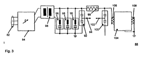
- Fig. 3 shows an electrical schematic diagram 80 of the test circuit, a resonant circuit, to which a part of the test components for tests with particularly high voltages is interconnectable.
- a resonant circuit is single-phase, ie where in Fig. 1 partially 3-phase indicated test components only one phase is used in this arrangement.
- An inverter 84 is connected via its inputs 82 3-phase with a power supply on site, for example, 400V, 50Hz. At the outputs of the inverter 84, which are connected to the terminals of the low voltage side of a second test transformer 96 are connected during operation to a regulated AC voltage. The transformed voltage at the top of the second test transformer 96 is smoothed with the filter elements 86, 88, 90.
- the number of 3 filter elements is shown here only schematically, of course, a higher number of filter elements is conceivable.
- the filter elements are preferably designed for respectively different frequencies, so that by selecting or interconnecting suitable filter elements on the respective boundary conditions of the high-voltage test can be received, of course, existing filter elements may be needed unused.
- a fourth voltage converter 92 is connected, which measures the alternating voltage generated by the inverter 84 and transformed by the second test transformer 96 and fed via a voltage tap 94 of the control device of the inverter 84, not shown.
- the frequency of the AC voltage is controlled so that the resonant circuit is excited in its resonant frequency.
- the resonant circuit mainly comprises a second high voltage choke 98, a device under test 104, and a capacitive fifth voltage divider 100.
- the high-voltage components are matched to one another such that a resonant frequency of about the usual 50Hz mains frequency results, for example, 70Hz - 150Hz, this depends in particular on the characteristics of the test sample to be tested.
- the test object 104 is a 3-phase power transformer whose low-side terminals 108 are each connected to a ground and whose upper-voltage-side terminals 106 are electrically connected in parallel to each other in the resonant circuit.
Landscapes
- Physics & Mathematics (AREA)
- General Physics & Mathematics (AREA)
- Testing Relating To Insulation (AREA)
- Testing Electric Properties And Detecting Electric Faults (AREA)
- Measuring Instrument Details And Bridges, And Automatic Balancing Devices (AREA)
- Rectifiers (AREA)
- X-Ray Techniques (AREA)
Claims (15)
- Arrangement de contrôle (10, 50) pour le contrôle de tension alternative de composants à haute tension (104) comprenant• au moins un onduleur (84), au moins un transformateur de contrôle (14, 96), au moins une bobine à haute tension (16, 36, 98) et au moins un composant à haute tension supplémentaire (18a, 18b, 18c, 22a, 22b, 22c, 86, 88, 90, 92) en tant que composants de contrôle,• un récipient (12) parallélépipédique commun dans lequel sont disposés au moins les composants de contrôle mentionnés,• un dispositif de déplacement (44),• un dispositif de guidage (20a, 20b, 20c, 52),caractérisé en ce que l'au moins une bobine à haute tension (16, 36, 98) peut être déplacée au moyen du dispositif de déplacement (44) à travers au moins une ouverture sur une surface de délimitation du récipient (12) de manière à sortir au moins partiellement hors de celui-ci et il est ainsi possible de réaliser une alternance entre une première variante d'arrangement de la bobine à haute tension à l'intérieur du récipient (12) parallélépipédique et une deuxième variante d'arrangement avec une distance d'isolation suffisante pour effectuer le contrôle de tension alternative et en ce que l'au moins un composant à haute tension supplémentaire (18a, 18b, 18c, 22a, 22b, 22c, 86, 88, 90, 92) peut être déplacé à l'intérieur du récipient (12) parallélépipédique au moyen du dispositif de guidage (20a, 20b, 20c, 52) d'une position de transport (18a, 18b, 18c, 22b) en une position de travail (32a, 32b, 32c, 64).
- Arrangement de contrôle selon la revendication 1, caractérisé en ce que l'au moins un composant à haute tension supplémentaire (18a, 18b, 18c, 22a, 22b, 22c, 86, 88, 90, 92) est un élément filtrant électrique (18a, 18b, 18c, 86, 88, 90).
- Arrangement de contrôle selon la revendication 1 ou 2, caractérisé en ce que l'au moins un composant à haute tension supplémentaire (18a, 18b, 18c, 22a, 22b, 22c, 86, 88, 90, 92) est un convertisseur de tension (22a, 22b, 22c, 92).
- Arrangement de contrôle selon l'une des revendications précédentes, caractérisé en ce que le dispositif de guidage (20a, 20b, 20c, 52) comprend un rail de guidage le long duquel l'au moins un composant à haute tension supplémentaire (18a, 18b, 18c, 22a, 22b, 22c, 86, 88, 90, 92) peut être déplacé.
- Arrangement de contrôle selon l'une des revendications précédentes, caractérisé en ce que l'au moins un composant à haute tension supplémentaire (18a, 18b, 18c, 22a, 22b, 22c, 86, 88, 90, 92) peut pivoter autour d'un axe de rotation.
- Arrangement de contrôle selon l'une des revendications précédentes, caractérisé en ce que l'au moins un composant à haute tension supplémentaire (18a, 18b, 18c, 22a, 22b, 22c, 86, 88, 90, 92) peut être bloqué en position de transport (18a, 18b, 18c, 22b) et/ou en position de travail (32a, 32b, 32c, 64).
- Arrangement de contrôle selon l'une des revendications précédentes, caractérisé en ce que l'au moins un composant à haute tension supplémentaire (18a, 18b, 18c, 22a, 22b, 22c, 86, 88, 90, 92) est amené et peut être guidé dans la zone supérieure du récipient (12) parallélépipédique.
- Arrangement de contrôle selon l'une des revendications précédentes, caractérisé en ce que des lignes de liaison électrique vers au moins un composant à haute tension supplémentaire (18a, 18b, 18c, 22a, 22b, 22c, 86, 88, 90, 92) sont posées dans la zone supérieure du récipient (12) parallélépipédique.
- Arrangement de contrôle selon la revendication 8, caractérisé en ce que les lignes de liaison sont des câbles qui sont gainés par une couche isolante.
- Arrangement de contrôle selon l'une des revendications précédentes, caractérisé en ce que le dispositif de guidage (20a, 20b, 20c, 52) comprend un mécanisme d'entraînement pour l'au moins un composant à haute tension supplémentaire (18a, 18b, 18c, 22a, 22b, 22c, 86, 88, 90, 92).
- Arrangement de contrôle selon l'une des revendications précédentes, caractérisé en ce que la position de travail (32a, 32b, 32c, 64) de l'au moins un composant à haute tension supplémentaire (18a, 18b, 18c, 22a, 22b, 22c, 86, 88, 90, 92) chevauche au moins partiellement une zone de la bobine (16) qui n'est pas déplacée à l'extérieur.
- Arrangement de contrôle selon l'une des revendications précédentes, caractérisé en ce qu'un diviseur de tension (100) peut être déplacé hors du récipient (12) parallélépipédique conjointement avec la bobine à haute tension (16, 36, 98).
- Arrangement de contrôle selon la revendication 12, caractérisé en ce que le diviseur de tension (100) peut être déplacé par rapport à la bobine à haute tension (16, 36, 98) avec un dispositif de déplacement supplémentaire.
- Arrangement de contrôle selon l'une des revendications précédentes, caractérisé en ce que le récipient (12) parallélépipédique est un conteneur transportable ayant des dimensions standard.
- Arrangement de contrôle selon l'une des revendications précédentes, caractérisé en ce que l'au moins une ouverture peut être fermée.
Priority Applications (1)
| Application Number | Priority Date | Filing Date | Title |
|---|---|---|---|
| EP09761392.1A EP2286254B2 (fr) | 2008-06-12 | 2009-05-27 | Dispositif d'essai pour des composants électriques à haute tension par courant alternatif |
Applications Claiming Priority (3)
| Application Number | Priority Date | Filing Date | Title |
|---|---|---|---|
| EP08010691.7A EP2133704B2 (fr) | 2008-06-12 | 2008-06-12 | Dispositif d'essai pour des composants électriques à haute tension par courant alternatif |
| EP09761392.1A EP2286254B2 (fr) | 2008-06-12 | 2009-05-27 | Dispositif d'essai pour des composants électriques à haute tension par courant alternatif |
| PCT/EP2009/003756 WO2009149829A1 (fr) | 2008-06-12 | 2009-05-27 | Système d'essai pour l'essai à la tension alternative de composants électriques à haute tension |
Publications (3)
| Publication Number | Publication Date |
|---|---|
| EP2286254A1 EP2286254A1 (fr) | 2011-02-23 |
| EP2286254B1 true EP2286254B1 (fr) | 2011-08-24 |
| EP2286254B2 EP2286254B2 (fr) | 2015-12-02 |
Family
ID=39960711
Family Applications (3)
| Application Number | Title | Priority Date | Filing Date |
|---|---|---|---|
| EP08010691.7A Active EP2133704B2 (fr) | 2008-06-12 | 2008-06-12 | Dispositif d'essai pour des composants électriques à haute tension par courant alternatif |
| EP09004940A Revoked EP2133888B1 (fr) | 2008-06-12 | 2009-04-03 | Dispositif d'essai pour des composants électriques à haute tension par courant alternatif |
| EP09761392.1A Active EP2286254B2 (fr) | 2008-06-12 | 2009-05-27 | Dispositif d'essai pour des composants électriques à haute tension par courant alternatif |
Family Applications Before (2)
| Application Number | Title | Priority Date | Filing Date |
|---|---|---|---|
| EP08010691.7A Active EP2133704B2 (fr) | 2008-06-12 | 2008-06-12 | Dispositif d'essai pour des composants électriques à haute tension par courant alternatif |
| EP09004940A Revoked EP2133888B1 (fr) | 2008-06-12 | 2009-04-03 | Dispositif d'essai pour des composants électriques à haute tension par courant alternatif |
Country Status (13)
| Country | Link |
|---|---|
| US (3) | US8427172B2 (fr) |
| EP (3) | EP2133704B2 (fr) |
| CN (2) | CN102057286B (fr) |
| AR (1) | AR072126A1 (fr) |
| AT (3) | ATE522817T1 (fr) |
| AU (3) | AU2009256991B9 (fr) |
| BR (3) | BRPI0915158B1 (fr) |
| CA (2) | CA2726427C (fr) |
| ES (2) | ES2371787T5 (fr) |
| RU (2) | RU2494410C2 (fr) |
| SA (1) | SA109300379B1 (fr) |
| UA (2) | UA105179C2 (fr) |
| WO (3) | WO2009149829A1 (fr) |
Families Citing this family (21)
| Publication number | Priority date | Publication date | Assignee | Title |
|---|---|---|---|---|
| DE102007059289B4 (de) * | 2007-12-08 | 2011-07-28 | Maschinenfabrik Reinhausen GmbH, 93059 | Vorrichtung zur Prüfung von Transformatoren |
| ATE522817T1 (de) | 2008-06-12 | 2011-09-15 | Abb Technology Ag | Prüfanordnung zur wechselspannungsprüfung von elektrischen hochspannungskomponenten |
| EP2378302B1 (fr) | 2008-06-12 | 2012-08-22 | ABB Technology AG | Dispositif d'essai pour des composants électriques à haute tension par tension de choc |
| DE102009023713B4 (de) * | 2009-06-03 | 2014-06-05 | Maschinenfabrik Reinhausen Gmbh | Vorrichtung zur Prüfung von Geräten der Hochspannungstechnik |
| GB2480455B (en) | 2010-05-18 | 2012-10-10 | Megger Instr Ltd | High voltage liquid dielectric test vessel |
| CN102285333B (zh) * | 2011-07-13 | 2012-10-03 | 苏州华电电气股份有限公司 | 超高压电力互感器校验车 |
| EP2590185B1 (fr) * | 2011-11-02 | 2014-04-02 | ABB Technology AG | Module de transformateur haute tension |
| ES2450468T3 (es) * | 2011-11-02 | 2014-03-24 | Abb Technology Ag | Contenedor de ensayo |
| DE102012101548B4 (de) * | 2012-02-27 | 2015-11-19 | Maschinenfabrik Reinhausen Gmbh | Prüfsystem und Verfahren für eine induzierte Spannungsprüfung sowie Verlustleistungsmessung von Prüfobjekten der Hochspannungstechnik |
| CA2874903C (fr) * | 2012-06-06 | 2019-04-30 | Prysmian S.P.A. | Systeme de derivation pour lignes electriques aeriennes |
| DE102012105045A1 (de) * | 2012-06-12 | 2013-12-12 | Maschinenfabrik Reinhausen Gmbh | Vorrichtung zum Kalibirieren eines Leistungsmesssystems für Leistungstransformatoren |
| RU2617832C2 (ru) * | 2012-07-25 | 2017-04-28 | Сан Пэтент Траст | Устройство базовой станции, терминальное устройство, способ передачи и способ приема |
| CN102944775B (zh) * | 2012-10-30 | 2014-10-22 | 苏州华电电气股份有限公司 | 一种基于高压变频电源的大容量变压器特性试验系统 |
| PL2747098T3 (pl) * | 2012-12-19 | 2016-06-30 | Abb Research Ltd | Układ transformatora do tłumienia chwilowych oscylacji napięcia |
| EP2853908B1 (fr) | 2013-09-25 | 2021-03-31 | ABB Power Grids Switzerland AG | Système de contrôle pour composants haute tension |
| EP2863236B1 (fr) * | 2013-10-18 | 2019-12-04 | ABB Schweiz AG | Système de contrôle pour composants haute tension |
| RU2659588C1 (ru) * | 2017-01-30 | 2018-07-03 | Илья Николаевич Джус | Инверторный испытатель трансформаторов |
| FR3074599B1 (fr) | 2017-12-05 | 2019-12-20 | Alstom Transport Technologies | Systeme de test d'un bloc de traction ferroviaire |
| RU2739702C1 (ru) * | 2019-12-02 | 2020-12-28 | Илья Николаевич Джус | Установка для испытания трансформаторов |
| US11876384B2 (en) * | 2020-12-15 | 2024-01-16 | Otis Elevator Company | Wireless power transfer device |
| WO2023106961A1 (fr) * | 2021-12-08 | 2023-06-15 | Федеральное Государственное Унитарное Предприятие "Российский Федеральный Ядерный Центр - Всероссийский Научно - Исследовательский Институт Технической Физики Имени Академика Е.И. Забабахина" | Installation haute tension mobile pour tester des transformateurs de puissance |
Family Cites Families (24)
| Publication number | Priority date | Publication date | Assignee | Title |
|---|---|---|---|---|
| DE521475C (de) * | 1929-03-28 | 1931-03-21 | Koch & Sterzel Akt Ges | Transformator, insbesondere Messwandler, fuer hohe Spannungen, bestehend aus in Kaskade geschalteten Einzelsystemen mit in Reihe liegenden Primaerwicklungen und Schub- und UEberkopplungswicklungen |
| US2032904A (en) | 1935-10-03 | 1936-03-03 | Westinghouse Electric & Mfg Co | Lightning-stroke generator |
| US2237812A (en) * | 1940-02-23 | 1941-04-08 | Gen Electric | Portable unit substation |
| US2551841A (en) * | 1946-11-27 | 1951-05-08 | Westinghouse Electric Corp | Electrical apparatus |
| DE1563442A1 (de) | 1966-12-08 | 1970-04-02 | Siemens Ag | Kurzschlussdrosselspule |
| DE2328375C3 (de) † | 1973-06-04 | 1978-12-14 | Transformatoren Union Ag, 7000 Stuttgart | Kondensatorbatterie zur Spannungssteuerung an Wicklungen von Transformatoren und Drosseln |
| AT330887B (de) | 1974-11-08 | 1976-07-26 | Leinweber Anstalt Ing Joh | Vorrichtung zum pressen von gekrümmten bremsbelägen |
| JPS5936091Y2 (ja) * | 1978-11-24 | 1984-10-05 | 株式会社明電舎 | 移動用変電設備 |
| US4427898A (en) † | 1981-12-22 | 1984-01-24 | Mitsubishi Denki Kabushiki Kaisha | Mobile power station apparatus |
| JPS58177915U (ja) † | 1982-05-20 | 1983-11-28 | 三菱電機株式会社 | 移動用電気装置 |
| SU1179234A1 (ru) | 1983-08-19 | 1985-09-15 | Проектно-конструкторское бюро электрогидравлики АН УССР | Устройство дл возбуждени сейсмических волн |
| JPS61102176A (ja) | 1984-10-24 | 1986-05-20 | Kansai Electric Power Co Inc:The | インパルス電圧発生装置 |
| JPH0738011B2 (ja) * | 1988-05-16 | 1995-04-26 | 株式会社日立製作所 | 高圧電力機器の異常診断システム |
| US5686697A (en) * | 1995-01-06 | 1997-11-11 | Metatech Corporation | Electrical circuit suspension system |
| RU2083824C1 (ru) | 1995-06-13 | 1997-07-10 | Научно-исследовательский институт высоких напряжений при Томском политехническом университете | Способ разрушения горных пород |
| DE19639023A1 (de) | 1996-09-23 | 1998-03-26 | Haefely Trench Ag | Impulsspannungsgeneratorschaltung |
| US6313640B1 (en) * | 1998-02-03 | 2001-11-06 | Abb Power T & D Company, Inc. | System and method for diagnosing and measuring partial discharge |
| WO2002051007A1 (fr) | 2000-12-20 | 2002-06-27 | Haefely Test Ag | Structure de cheminee porteuse pour generateur d'impulsions electriques |
| US6586697B1 (en) * | 2002-07-26 | 2003-07-01 | Pauwels Contracting Inc. | Transportable electrical switching assembly with high voltage circuit interrupter |
| US6586671B1 (en) | 2002-08-06 | 2003-07-01 | Interrail Signal, Inc. | Above ground track signal terminal apparatus |
| CN2574062Y (zh) * | 2002-10-17 | 2003-09-17 | 北京安控科技发展有限公司 | 电流信号调理电路 |
| RU2222858C1 (ru) * | 2002-10-31 | 2004-01-27 | Механошин Борис Иосифович | Устройство для дистанционного контроля состояния провода воздушной линии электропередачи (варианты) |
| ATE522817T1 (de) | 2008-06-12 | 2011-09-15 | Abb Technology Ag | Prüfanordnung zur wechselspannungsprüfung von elektrischen hochspannungskomponenten |
| DE202009001837U1 (de) | 2009-02-13 | 2009-04-16 | Fachhochschule Flensburg | Mobiler Norm-Blitzstoßspannungsgenerator |
-
2008
- 2008-06-12 AT AT08010691T patent/ATE522817T1/de active
- 2008-06-12 ES ES08010691.7T patent/ES2371787T5/es active Active
- 2008-06-12 EP EP08010691.7A patent/EP2133704B2/fr active Active
-
2009
- 2009-04-03 AT AT09004940T patent/ATE520133T1/de active
- 2009-04-03 EP EP09004940A patent/EP2133888B1/fr not_active Revoked
- 2009-04-06 UA UAA201014832A patent/UA105179C2/uk unknown
- 2009-05-27 ES ES09761392T patent/ES2372013T3/es active Active
- 2009-05-27 EP EP09761392.1A patent/EP2286254B2/fr active Active
- 2009-05-27 AU AU2009256991A patent/AU2009256991B9/en active Active
- 2009-05-27 UA UAA201014834A patent/UA100158C2/uk unknown
- 2009-05-27 CN CN200980122462.8A patent/CN102057286B/zh active Active
- 2009-05-27 AT AT09761392T patent/ATE521900T1/de active
- 2009-05-27 WO PCT/EP2009/003756 patent/WO2009149829A1/fr active Application Filing
- 2009-05-27 BR BRPI0915158-3A patent/BRPI0915158B1/pt active IP Right Grant
- 2009-05-27 RU RU2011100159/28A patent/RU2494410C2/ru active
- 2009-05-27 CA CA2726427A patent/CA2726427C/fr active Active
- 2009-06-04 RU RU2011100174/28A patent/RU2497138C2/ru not_active IP Right Cessation
- 2009-06-04 BR BRPI0915211A patent/BRPI0915211A8/pt not_active Application Discontinuation
- 2009-06-04 CA CA2726437A patent/CA2726437C/fr active Active
- 2009-06-04 CN CN200980122461.3A patent/CN102057283B/zh active Active
- 2009-06-04 WO PCT/EP2009/003977 patent/WO2009149857A1/fr active Application Filing
- 2009-06-04 AU AU2009256936A patent/AU2009256936A1/en not_active Abandoned
- 2009-06-04 WO PCT/EP2009/004001 patent/WO2009149866A1/fr active Application Filing
- 2009-06-04 BR BRPI0915110-9A patent/BRPI0915110B1/pt active IP Right Grant
- 2009-06-12 AR ARP090102141A patent/AR072126A1/es not_active Application Discontinuation
- 2009-06-13 SA SA109300379A patent/SA109300379B1/ar unknown
-
2010
- 2010-12-08 US US12/963,044 patent/US8427172B2/en active Active
- 2010-12-08 US US12/963,144 patent/US8952704B2/en active Active
- 2010-12-09 US US12/963,941 patent/US8643381B2/en active Active
-
2014
- 2014-06-18 AU AU2014203314A patent/AU2014203314B2/en not_active Ceased
Also Published As
Similar Documents
| Publication | Publication Date | Title |
|---|---|---|
| EP2286254B1 (fr) | Dispositif d'essai pour des composants électriques à haute tension par courant alternatif | |
| EP2438450B1 (fr) | Dispositif permettant de vérifier des appareils de la technique de haute tension | |
| EP2230522A1 (fr) | Procédé et dispositif de surveillance d'isolation d'un réseau IT | |
| DE102010060696B4 (de) | Gasisolierter Spannungswandler | |
| EP2590185B1 (fr) | Module de transformateur haute tension | |
| WO2013083850A2 (fr) | Dispositif de contrôle pour réaliser des tests de fonctionnement sur des générateurs d'énergie | |
| EP2859374B1 (fr) | Dispositif pour calibrer un système de mesure de puissance pour des transformateurs de puissance | |
| EP3447507A1 (fr) | Dispositif d'essai de décharge partielle mobile | |
| EP2133889A1 (fr) | Bobine d'arrêt et agencement de vérification comportant la bobine d'arrêt | |
| EP2362514B1 (fr) | Dispositif de réduction du courant de défaut à la terre | |
| WO2018153433A1 (fr) | Convertisseur de puissance modulaire à plusieurs niveaux | |
| DE4418124A1 (de) | Vorrichtung zum Erkennen einer Isolationsverschlechterung an Stromversorgungsleitungen | |
| EP3385731B1 (fr) | Dispositif de mesure de courant de fuite à la terre | |
| DE2735756A1 (de) | Verfahren und vorrichtung zur erdschlussrichtungsbestimmung in kompensierten netzen | |
| EP2853908B1 (fr) | Système de contrôle pour composants haute tension | |
| DE102012105054B4 (de) | Vorrichtung zur Leistungsmessung | |
| DE102010004971A1 (de) | Vorrichtung für eine Schaltanlage | |
| Schufft et al. | Resonant test system with variable frequency for on-site testing and diagnostics of cables | |
| DE102007029775B4 (de) | Messwandleranordnung mit mehreren Sekundärkreisen | |
| EP3850720A1 (fr) | Bobine d'étranglement réglable magnétiquement dans un montage en série | |
| DE1955712A1 (de) | Traegerfrequenzsperrung durch Ferritkoerper an elektrischen Leitungen | |
| CH154226A (de) | Strom- und Spannungswandler. |
Legal Events
| Date | Code | Title | Description |
|---|---|---|---|
| PUAI | Public reference made under article 153(3) epc to a published international application that has entered the european phase |
Free format text: ORIGINAL CODE: 0009012 |
|
| 17P | Request for examination filed |
Effective date: 20101109 |
|
| AK | Designated contracting states |
Kind code of ref document: A1 Designated state(s): AT BE BG CH CY CZ DE DK EE ES FI FR GB GR HR HU IE IS IT LI LT LU LV MC MK MT NL NO PL PT RO SE SI SK TR |
|
| AX | Request for extension of the european patent |
Extension state: AL BA RS |
|
| GRAP | Despatch of communication of intention to grant a patent |
Free format text: ORIGINAL CODE: EPIDOSNIGR1 |
|
| RTI1 | Title (correction) |
Free format text: TEST ASSEMBLY FOR AC TESTING OF HIGH VOLTAGE ELECTRICAL COMPONENTS |
|
| DAX | Request for extension of the european patent (deleted) | ||
| GRAS | Grant fee paid |
Free format text: ORIGINAL CODE: EPIDOSNIGR3 |
|
| GRAA | (expected) grant |
Free format text: ORIGINAL CODE: 0009210 |
|
| AK | Designated contracting states |
Kind code of ref document: B1 Designated state(s): AT BE BG CH CY CZ DE DK EE ES FI FR GB GR HR HU IE IS IT LI LT LU LV MC MK MT NL NO PL PT RO SE SI SK TR |
|
| REG | Reference to a national code |
Ref country code: GB Ref legal event code: FG4D Free format text: NOT ENGLISH |
|
| REG | Reference to a national code |
Ref country code: CH Ref legal event code: EP |
|
| REG | Reference to a national code |
Ref country code: IE Ref legal event code: FG4D Free format text: LANGUAGE OF EP DOCUMENT: GERMAN |
|
| REG | Reference to a national code |
Ref country code: DE Ref legal event code: R096 Ref document number: 502009001204 Country of ref document: DE Effective date: 20111020 |
|
| REG | Reference to a national code |
Ref country code: NL Ref legal event code: VDEP Effective date: 20110824 |
|
| REG | Reference to a national code |
Ref country code: ES Ref legal event code: FG2A Ref document number: 2372013 Country of ref document: ES Kind code of ref document: T3 Effective date: 20120112 |
|
| LTIE | Lt: invalidation of european patent or patent extension |
Effective date: 20110824 |
|
| PG25 | Lapsed in a contracting state [announced via postgrant information from national office to epo] |
Ref country code: LT Free format text: LAPSE BECAUSE OF FAILURE TO SUBMIT A TRANSLATION OF THE DESCRIPTION OR TO PAY THE FEE WITHIN THE PRESCRIBED TIME-LIMIT Effective date: 20110824 Ref country code: NL Free format text: LAPSE BECAUSE OF FAILURE TO SUBMIT A TRANSLATION OF THE DESCRIPTION OR TO PAY THE FEE WITHIN THE PRESCRIBED TIME-LIMIT Effective date: 20110824 Ref country code: NO Free format text: LAPSE BECAUSE OF FAILURE TO SUBMIT A TRANSLATION OF THE DESCRIPTION OR TO PAY THE FEE WITHIN THE PRESCRIBED TIME-LIMIT Effective date: 20111124 Ref country code: HR Free format text: LAPSE BECAUSE OF FAILURE TO SUBMIT A TRANSLATION OF THE DESCRIPTION OR TO PAY THE FEE WITHIN THE PRESCRIBED TIME-LIMIT Effective date: 20110824 Ref country code: FI Free format text: LAPSE BECAUSE OF FAILURE TO SUBMIT A TRANSLATION OF THE DESCRIPTION OR TO PAY THE FEE WITHIN THE PRESCRIBED TIME-LIMIT Effective date: 20110824 Ref country code: IS Free format text: LAPSE BECAUSE OF FAILURE TO SUBMIT A TRANSLATION OF THE DESCRIPTION OR TO PAY THE FEE WITHIN THE PRESCRIBED TIME-LIMIT Effective date: 20111224 Ref country code: SE Free format text: LAPSE BECAUSE OF FAILURE TO SUBMIT A TRANSLATION OF THE DESCRIPTION OR TO PAY THE FEE WITHIN THE PRESCRIBED TIME-LIMIT Effective date: 20110824 Ref country code: PT Free format text: LAPSE BECAUSE OF FAILURE TO SUBMIT A TRANSLATION OF THE DESCRIPTION OR TO PAY THE FEE WITHIN THE PRESCRIBED TIME-LIMIT Effective date: 20111226 |
|
| PG25 | Lapsed in a contracting state [announced via postgrant information from national office to epo] |
Ref country code: GR Free format text: LAPSE BECAUSE OF FAILURE TO SUBMIT A TRANSLATION OF THE DESCRIPTION OR TO PAY THE FEE WITHIN THE PRESCRIBED TIME-LIMIT Effective date: 20111125 Ref country code: LV Free format text: LAPSE BECAUSE OF FAILURE TO SUBMIT A TRANSLATION OF THE DESCRIPTION OR TO PAY THE FEE WITHIN THE PRESCRIBED TIME-LIMIT Effective date: 20110824 Ref country code: CY Free format text: LAPSE BECAUSE OF FAILURE TO SUBMIT A TRANSLATION OF THE DESCRIPTION OR TO PAY THE FEE WITHIN THE PRESCRIBED TIME-LIMIT Effective date: 20110824 Ref country code: SI Free format text: LAPSE BECAUSE OF FAILURE TO SUBMIT A TRANSLATION OF THE DESCRIPTION OR TO PAY THE FEE WITHIN THE PRESCRIBED TIME-LIMIT Effective date: 20110824 Ref country code: PL Free format text: LAPSE BECAUSE OF FAILURE TO SUBMIT A TRANSLATION OF THE DESCRIPTION OR TO PAY THE FEE WITHIN THE PRESCRIBED TIME-LIMIT Effective date: 20110824 |
|
| REG | Reference to a national code |
Ref country code: IE Ref legal event code: FD4D |
|
| PG25 | Lapsed in a contracting state [announced via postgrant information from national office to epo] |
Ref country code: IE Free format text: LAPSE BECAUSE OF FAILURE TO SUBMIT A TRANSLATION OF THE DESCRIPTION OR TO PAY THE FEE WITHIN THE PRESCRIBED TIME-LIMIT Effective date: 20110824 Ref country code: SK Free format text: LAPSE BECAUSE OF FAILURE TO SUBMIT A TRANSLATION OF THE DESCRIPTION OR TO PAY THE FEE WITHIN THE PRESCRIBED TIME-LIMIT Effective date: 20110824 Ref country code: CZ Free format text: LAPSE BECAUSE OF FAILURE TO SUBMIT A TRANSLATION OF THE DESCRIPTION OR TO PAY THE FEE WITHIN THE PRESCRIBED TIME-LIMIT Effective date: 20110824 |
|
| PG25 | Lapsed in a contracting state [announced via postgrant information from national office to epo] |
Ref country code: EE Free format text: LAPSE BECAUSE OF FAILURE TO SUBMIT A TRANSLATION OF THE DESCRIPTION OR TO PAY THE FEE WITHIN THE PRESCRIBED TIME-LIMIT Effective date: 20110824 Ref country code: RO Free format text: LAPSE BECAUSE OF FAILURE TO SUBMIT A TRANSLATION OF THE DESCRIPTION OR TO PAY THE FEE WITHIN THE PRESCRIBED TIME-LIMIT Effective date: 20110824 |
|
| PLBI | Opposition filed |
Free format text: ORIGINAL CODE: 0009260 |
|
| PG25 | Lapsed in a contracting state [announced via postgrant information from national office to epo] |
Ref country code: DK Free format text: LAPSE BECAUSE OF FAILURE TO SUBMIT A TRANSLATION OF THE DESCRIPTION OR TO PAY THE FEE WITHIN THE PRESCRIBED TIME-LIMIT Effective date: 20110824 |
|
| PLAX | Notice of opposition and request to file observation + time limit sent |
Free format text: ORIGINAL CODE: EPIDOSNOBS2 |
|
| 26 | Opposition filed |
Opponent name: HIGHVOLT PRUEFTECHNIK DRESDEN GMBH Effective date: 20120523 |
|
| REG | Reference to a national code |
Ref country code: DE Ref legal event code: R026 Ref document number: 502009001204 Country of ref document: DE Effective date: 20120523 |
|
| PLBB | Reply of patent proprietor to notice(s) of opposition received |
Free format text: ORIGINAL CODE: EPIDOSNOBS3 |
|
| BERE | Be: lapsed |
Owner name: ABB TECHNOLOGY A.G. Effective date: 20120531 |
|
| PG25 | Lapsed in a contracting state [announced via postgrant information from national office to epo] |
Ref country code: MC Free format text: LAPSE BECAUSE OF NON-PAYMENT OF DUE FEES Effective date: 20120531 |
|
| PG25 | Lapsed in a contracting state [announced via postgrant information from national office to epo] |
Ref country code: MK Free format text: LAPSE BECAUSE OF FAILURE TO SUBMIT A TRANSLATION OF THE DESCRIPTION OR TO PAY THE FEE WITHIN THE PRESCRIBED TIME-LIMIT Effective date: 20110824 Ref country code: BE Free format text: LAPSE BECAUSE OF NON-PAYMENT OF DUE FEES Effective date: 20120531 |
|
| PG25 | Lapsed in a contracting state [announced via postgrant information from national office to epo] |
Ref country code: BG Free format text: LAPSE BECAUSE OF FAILURE TO SUBMIT A TRANSLATION OF THE DESCRIPTION OR TO PAY THE FEE WITHIN THE PRESCRIBED TIME-LIMIT Effective date: 20111124 |
|
| PG25 | Lapsed in a contracting state [announced via postgrant information from national office to epo] |
Ref country code: MT Free format text: LAPSE BECAUSE OF FAILURE TO SUBMIT A TRANSLATION OF THE DESCRIPTION OR TO PAY THE FEE WITHIN THE PRESCRIBED TIME-LIMIT Effective date: 20110824 |
|
| REG | Reference to a national code |
Ref country code: CH Ref legal event code: PL |
|
| PG25 | Lapsed in a contracting state [announced via postgrant information from national office to epo] |
Ref country code: LI Free format text: LAPSE BECAUSE OF NON-PAYMENT OF DUE FEES Effective date: 20130531 Ref country code: CH Free format text: LAPSE BECAUSE OF NON-PAYMENT OF DUE FEES Effective date: 20130531 |
|
| PG25 | Lapsed in a contracting state [announced via postgrant information from national office to epo] |
Ref country code: TR Free format text: LAPSE BECAUSE OF FAILURE TO SUBMIT A TRANSLATION OF THE DESCRIPTION OR TO PAY THE FEE WITHIN THE PRESCRIBED TIME-LIMIT Effective date: 20110824 |
|
| PG25 | Lapsed in a contracting state [announced via postgrant information from national office to epo] |
Ref country code: LU Free format text: LAPSE BECAUSE OF NON-PAYMENT OF DUE FEES Effective date: 20120527 |
|
| PG25 | Lapsed in a contracting state [announced via postgrant information from national office to epo] |
Ref country code: HU Free format text: LAPSE BECAUSE OF FAILURE TO SUBMIT A TRANSLATION OF THE DESCRIPTION OR TO PAY THE FEE WITHIN THE PRESCRIBED TIME-LIMIT Effective date: 20090527 |
|
| PLBP | Opposition withdrawn |
Free format text: ORIGINAL CODE: 0009264 |
|
| PLAY | Examination report in opposition despatched + time limit |
Free format text: ORIGINAL CODE: EPIDOSNORE2 |
|
| PLAB | Opposition data, opponent's data or that of the opponent's representative modified |
Free format text: ORIGINAL CODE: 0009299OPPO |
|
| REG | Reference to a national code |
Ref country code: FR Ref legal event code: PLFP Year of fee payment: 7 |
|
| REG | Reference to a national code |
Ref country code: AT Ref legal event code: MM01 Ref document number: 521900 Country of ref document: AT Kind code of ref document: T Effective date: 20140527 |
|
| PGFP | Annual fee paid to national office [announced via postgrant information from national office to epo] |
Ref country code: ES Payment date: 20150527 Year of fee payment: 7 |
|
| PG25 | Lapsed in a contracting state [announced via postgrant information from national office to epo] |
Ref country code: AT Free format text: LAPSE BECAUSE OF NON-PAYMENT OF DUE FEES Effective date: 20140527 |
|
| PUAH | Patent maintained in amended form |
Free format text: ORIGINAL CODE: 0009272 |
|
| STAA | Information on the status of an ep patent application or granted ep patent |
Free format text: STATUS: PATENT MAINTAINED AS AMENDED |
|
| 27A | Patent maintained in amended form |
Effective date: 20151202 |
|
| AK | Designated contracting states |
Kind code of ref document: B2 Designated state(s): AT BE BG CH CY CZ DE DK EE ES FI FR GB GR HR HU IE IS IT LI LT LU LV MC MK MT NL NO PL PT RO SE SI SK TR |
|
| REG | Reference to a national code |
Ref country code: DE Ref legal event code: R102 Ref document number: 502009001204 Country of ref document: DE |
|
| PG25 | Lapsed in a contracting state [announced via postgrant information from national office to epo] |
Ref country code: ES Free format text: LAPSE BECAUSE OF FAILURE TO SUBMIT A TRANSLATION OF THE DESCRIPTION OR TO PAY THE FEE WITHIN THE PRESCRIBED TIME-LIMIT Effective date: 20151202 |
|
| REG | Reference to a national code |
Ref country code: FR Ref legal event code: PLFP Year of fee payment: 8 |
|
| REG | Reference to a national code |
Ref country code: DE Ref legal event code: R081 Ref document number: 502009001204 Country of ref document: DE Owner name: HITACHI ENERGY SWITZERLAND AG, CH Free format text: FORMER OWNER: ABB TECHNOLOGY AG, ZUERICH, CH Ref country code: DE Ref legal event code: R081 Ref document number: 502009001204 Country of ref document: DE Owner name: ABB POWER GRIDS SWITZERLAND AG, CH Free format text: FORMER OWNER: ABB TECHNOLOGY AG, ZUERICH, CH Ref country code: DE Ref legal event code: R081 Ref document number: 502009001204 Country of ref document: DE Owner name: ABB SCHWEIZ AG, CH Free format text: FORMER OWNER: ABB TECHNOLOGY AG, ZUERICH, CH |
|
| PGFP | Annual fee paid to national office [announced via postgrant information from national office to epo] |
Ref country code: IT Payment date: 20160524 Year of fee payment: 8 |
|
| REG | Reference to a national code |
Ref country code: FR Ref legal event code: PLFP Year of fee payment: 9 |
|
| REG | Reference to a national code |
Ref country code: FR Ref legal event code: PLFP Year of fee payment: 10 |
|
| REG | Reference to a national code |
Ref country code: GB Ref legal event code: 732E Free format text: REGISTERED BETWEEN 20180426 AND 20180502 |
|
| PG25 | Lapsed in a contracting state [announced via postgrant information from national office to epo] |
Ref country code: IT Free format text: LAPSE BECAUSE OF NON-PAYMENT OF DUE FEES Effective date: 20170527 |
|
| REG | Reference to a national code |
Ref country code: FR Ref legal event code: TP Owner name: ABB SCHWEIZ AG, CH Effective date: 20180912 |
|
| REG | Reference to a national code |
Ref country code: DE Ref legal event code: R081 Ref document number: 502009001204 Country of ref document: DE Owner name: HITACHI ENERGY SWITZERLAND AG, CH Free format text: FORMER OWNER: ABB SCHWEIZ AG, BADEN, CH Ref country code: DE Ref legal event code: R081 Ref document number: 502009001204 Country of ref document: DE Owner name: HITACHI ENERGY LTD, CH Free format text: FORMER OWNER: ABB SCHWEIZ AG, BADEN, CH Ref country code: DE Ref legal event code: R081 Ref document number: 502009001204 Country of ref document: DE Owner name: ABB POWER GRIDS SWITZERLAND AG, CH Free format text: FORMER OWNER: ABB SCHWEIZ AG, BADEN, CH |
|
| REG | Reference to a national code |
Ref country code: GB Ref legal event code: 732E Free format text: REGISTERED BETWEEN 20210909 AND 20210915 |
|
| REG | Reference to a national code |
Ref country code: DE Ref legal event code: R081 Ref document number: 502009001204 Country of ref document: DE Owner name: HITACHI ENERGY SWITZERLAND AG, CH Free format text: FORMER OWNER: ABB POWER GRIDS SWITZERLAND AG, BADEN, CH Ref country code: DE Ref legal event code: R081 Ref document number: 502009001204 Country of ref document: DE Owner name: HITACHI ENERGY LTD, CH Free format text: FORMER OWNER: ABB POWER GRIDS SWITZERLAND AG, BADEN, CH |
|
| P01 | Opt-out of the competence of the unified patent court (upc) registered |
Effective date: 20230527 |
|
| PGFP | Annual fee paid to national office [announced via postgrant information from national office to epo] |
Ref country code: FR Payment date: 20230526 Year of fee payment: 15 Ref country code: DE Payment date: 20230519 Year of fee payment: 15 |
|
| PGFP | Annual fee paid to national office [announced via postgrant information from national office to epo] |
Ref country code: GB Payment date: 20230524 Year of fee payment: 15 |
|
| REG | Reference to a national code |
Ref country code: DE Ref legal event code: R082 Ref document number: 502009001204 Country of ref document: DE Representative=s name: DENNEMEYER & ASSOCIATES S.A., DE Ref country code: DE Ref legal event code: R081 Ref document number: 502009001204 Country of ref document: DE Owner name: HITACHI ENERGY LTD, CH Free format text: FORMER OWNER: HITACHI ENERGY SWITZERLAND AG, BADEN, CH |